EP0076070A1 - Transcutaneous signal transmission system - Google Patents
Transcutaneous signal transmission system Download PDFInfo
- Publication number
- EP0076070A1 EP0076070A1 EP82304921A EP82304921A EP0076070A1 EP 0076070 A1 EP0076070 A1 EP 0076070A1 EP 82304921 A EP82304921 A EP 82304921A EP 82304921 A EP82304921 A EP 82304921A EP 0076070 A1 EP0076070 A1 EP 0076070A1
- Authority
- EP
- European Patent Office
- Prior art keywords
- transmitter
- tuned circuit
- coupling
- receiver
- tuned
- Prior art date
- Legal status (The legal status is an assumption and is not a legal conclusion. Google has not performed a legal analysis and makes no representation as to the accuracy of the status listed.)
- Granted
Links
Images


Classifications
-
- A—HUMAN NECESSITIES
- A61—MEDICAL OR VETERINARY SCIENCE; HYGIENE
- A61F—FILTERS IMPLANTABLE INTO BLOOD VESSELS; PROSTHESES; DEVICES PROVIDING PATENCY TO, OR PREVENTING COLLAPSING OF, TUBULAR STRUCTURES OF THE BODY, e.g. STENTS; ORTHOPAEDIC, NURSING OR CONTRACEPTIVE DEVICES; FOMENTATION; TREATMENT OR PROTECTION OF EYES OR EARS; BANDAGES, DRESSINGS OR ABSORBENT PADS; FIRST-AID KITS
- A61F11/00—Methods or devices for treatment of the ears or hearing sense; Non-electric hearing aids; Methods or devices for enabling ear patients to achieve auditory perception through physiological senses other than hearing sense; Protective devices for the ears, carried on the body or in the hand
- A61F11/04—Methods or devices for enabling ear patients to achieve auditory perception through physiological senses other than hearing sense, e.g. through the touch sense
-
- A—HUMAN NECESSITIES
- A61—MEDICAL OR VETERINARY SCIENCE; HYGIENE
- A61N—ELECTROTHERAPY; MAGNETOTHERAPY; RADIATION THERAPY; ULTRASOUND THERAPY
- A61N1/00—Electrotherapy; Circuits therefor
- A61N1/18—Applying electric currents by contact electrodes
- A61N1/32—Applying electric currents by contact electrodes alternating or intermittent currents
- A61N1/36—Applying electric currents by contact electrodes alternating or intermittent currents for stimulation
- A61N1/372—Arrangements in connection with the implantation of stimulators
- A61N1/378—Electrical supply
- A61N1/3787—Electrical supply from an external energy source
-
- Y—GENERAL TAGGING OF NEW TECHNOLOGICAL DEVELOPMENTS; GENERAL TAGGING OF CROSS-SECTIONAL TECHNOLOGIES SPANNING OVER SEVERAL SECTIONS OF THE IPC; TECHNICAL SUBJECTS COVERED BY FORMER USPC CROSS-REFERENCE ART COLLECTIONS [XRACs] AND DIGESTS
- Y10—TECHNICAL SUBJECTS COVERED BY FORMER USPC
- Y10S—TECHNICAL SUBJECTS COVERED BY FORMER USPC CROSS-REFERENCE ART COLLECTIONS [XRACs] AND DIGESTS
- Y10S128/00—Surgery
- Y10S128/903—Radio telemetry
Definitions
- This invention relates generally to systems for transmitting electrical signals into the body of a patient, and more particularly the invention relates to the transmission of signals to a receiver which is implanted in the body.
- Transcutaneous signal transmission systems are known and widely utilized for neural and muscle stimulation. Such systems are generally preferred over other transmission systems such as the use of implanted batteries or the use of direct percutaneous wiring.
- a transmitter transmits a modulated signal to the implanted receiver via two inductively coupled coils.
- the coils are part of tuned circuits which can cooperatively function as a band pass filter.
- inductive transmission systems have been designed for optimum efficiency with a consequential dependence of induced voltage in the implanted coil on exact positioning of the transmitter coil.
- the inductive transmission system has limitations in effectiveness.
- an object of the present invention is an improved transcutaneous signal transmission system which utilizes inductively coupled coils.
- Another object of the invention is the use of inductively coupled coils in a transcutaneous transmission system which have improved relative position tolerance.
- Still another object of the invention is an improved method of transmitting signals by inductively coupled coils.
- a transcutaneous signal transmission system in which signals are transmitted from a transmitter means outside of a patient to a receiver means which is implanted in the patient is characterized by a first tuned circuit in the transmitter means and a second tuned circuit in the receiver means which are positioned to achieve essentially critical coupling with optimal displacement tolerance of the first and second tuned circuits.
- the positioning tolerance of the transmitter tuned circuit coupl- ling coil with respect to the receiver tuned circuit coupling coil for achieving essentially critical coupling of the two coils is enhanced by providing a transmitter tuned circuit and a receiver tuned circuit having quality values, Q, greater than 5 with the transmitter tuned circuit having a quality preferably 3 times larger than the receiver tuned circuit:
- Critical coupling can be determined by measuring the mode resistance of the transmitter when not loaded by the receiver and then placing the transmitter coil with respect to the receiver coil so that the mode resistance of the transmitter decreases to one-half of the unloaded case. Load resistance can best be measured by observing the rf collector voltage of the output transistor.
- Figure 1 is a generalized electrical schematic of a transcutaneous signal transmission system comprising a transmitter tuned circuit shown generally at 10 and a receiver tuned circuit showing generally at 12.
- the transmitter tuned circuit 10 is driven by an RF amplifier transistor 14 and comprises resistor Rl, capacitor Cl and inductor Ll all connected in parallel.
- the receiver tuned circuit comprises inductor L2, capacitor C2, and a load resistor R2 all connected in parallel.
- the two coils Ll, L2 have a mutual inductance designated M.
- the coupling coefficient of the 2 coils can be described in terms of the mutual inductance M and the inductances Ll and L2 as follows:
- the coupling coefficient may be normalized as follows:
- critical coupling refers to a band pass filter consisting of two tuned circuits being driven by a current source, and at critical coupling the output voltage reaches a maximum. The output voltage is lower for both increased coupling, or overcoupling, and for decreased coupling, or undercoupling.
- Critical distance is the space between a transmitter coil and receiver coil at which critical coupling occurs.
- Transitional coupling is the amount of coupling necessary to obtain a transition of the transimpedance of the two coils from a shape with one maximum to a shape possessing two maxima.
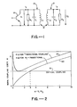
- Curve 18 is a plot of the transitional coupling which is necessary to obtain a transition of the absolute value of the transimpedance from a shape with one maximum to a shape having two maxima. As noted by curve 18 transitional coupling is dependent on the quality factors.
- the input transitional coupling or the amount of coupling necessary to obtain a transition of the absolute value of the frequency dependent input impedance is illustrated by curve 20.
- the dependence of the induced voltage in the implanted coil on coil separation shows a flat maximum.
- the coupling may be changed by varying the spacing or the lateral displacement to some extent with only minor changes in output voltage.
- the transmission system is optimized for position tolerance.
- FIG. 3 is a block diagram of auditory stimulation apparatus in accordance with the invention and Figures 4 and 5 which are schematic diagrams of specific embodiments of the system of Figure 3.
- a microphone 52 has its output applied to speech processor electronics shown as being enclosed by the broken line box 54. Included in the speech processor channel is a gain controlled amplifier 56 which receives as its input the electrical output from the microphone 52 and the output from the gain controlled amplifier 56 is applied through a band-pass filter 58 to a so-called isoloudness frequency adjustment circuit 60.
- the speech processor electronics 54 further includes a dynamic range compression circuit 62 which may either precede or follow the isoloudness frequency adjustment circuit 60.
- the output from the speech processor 54 is arranged to modulate the output from an R F oscillator in the AM transmitter module 64.
- the modulated output from the transmitter is applied across a transmitting coil 66 and a capacitor 68, these last mentioned two components being designed to cooperate as a tuned circuit 70.
- the implant unit 36 is shown to the right of the skin interface 72 and includes the receiver coil 22 which has a capacitor 74 connected in parallel with it.
- the parallel combination of the receiving coil 22 and the capacitor 74 forms a tuned receiver circuit 76.
- the output from the tuned receiver circuit is coupled as an input to a diode demodulator network 78 which functions in a conventional fashion to remove the modulation envelope from the RF carrier.
- the output from the diode demodulator is applied via the leads 24 to the active and indifferent electrode surfaces.
- the construction and operation of the speech processor electronics 54 is fully set forth and described in our co-pending application Serial No. 267,405, filed May 26, 1981, and, hence, it is believed unnecessary to explain that apparatus here.
- the contraction of the AM transmitter module 64 will be described in greater detail with reference to the electrical schematic diagram of Figure 4.
- the microphone pick-up 52 and the speech processor module 54 connected to it are shown as being coupled through a resistor 80 to a first terminal 82 of the secondary winding 84 of a transformer indicated generally by numeral 86.
- the primary winding 88 of the transformer is coupled across the output of an RF oscillator 90.
- the terminal 82 has a decoupling capacitor 92 connected between it and ground. This capacitor provides RF decoupling in a conventional fashion.
- the other terminal of the secondary winding 84 is connected directly to the base electrode of an NPN transistor 94.
- the emitter electrode of the transistor is connected to ground and its collector electrode is tied to an intermediate terminal 96 of a transmitting coil 66.
- a capacitor 68 is connected directly in parallel with the entire transmitting coil 66 and the requisite DC bias voltage for the transmitter 94 is applied at terminal 100.
- a further RF decoupling capacitor 102 is connected between ground and the common junction of the coil 66 and the capacitor 68.
- the implanted receiver module 36 comprises a receiving coil 22 and a tuning capacitor 74.
- the demodulator portion of the receiver comprises a semiconductor diode 104 having its anode connected to an intermediate terminal 106 on the receiving coil 22 and its cathode electrode connected to a junction point 108.
- a resistor 110 and a capacitor 112 are connected in parallel with one another between the junction point 108 and the outer terminal 114 of the coil 22.
- a blocking capacitor 116 is disposed in series between the junction point 108 and the active electrode.
- the second electrode is tied directly to the aforementioned junction point 114.
- the modulation signal which is a speech derived, time varying wave, originates at the output of the speech processor 54 and is applied to the transistor modulator via resistor 80 as is the RF carrier from the oscillator 90 via the transformer coupled to the base of the transistor 94.
- the capacitor 92 as well as the capacitor 102 serve to decouple the RF signal from the DC supply.
- the collector of the modulation transistor 94 is connected to the tap of the tuned transmitter circuit which includes the coil 66 and the capacitor 68.
- the transmitter coil 66 inductively couples the modulated carrier signal to the implanted receiver coil 22 which, together with the capacitor 74, also comprises a tuned receiver circuit.
- the received signal is demodulated by the semiconductor diode 104 in a conventional fashion with capacitor 112 providing RF decoupling and resistor 110 providing the requisite DC path to ground.
- the capacitor 116 serves to block any DC current from reaching the electrodes.
- the combination of the tuned transmitter circuit and the tuned receiver circuit comprise a band-pass filter network. It has been found that the stimulating voltage becomes highly independent of relative position between the transmitter coil 66 and the receiver coil 22 when the transmitter coil is positioned at the critical distance relative to the receiving coil.
- the critical distance refers to the spacing between the transmitter and receiver coil at which critical coupling occurs. If the spacing is decreased from the critical distance, over-coupling results and, similarly, when the spacing between the two coils exceeds the critical distance, there is under-coupling.
- the effective critical coupling ensures a relatively stable output voltage over a coil spacing range which is in the vicinity of the critical distance.
- the transimpedance, r which is the ratio of the voltage across the receiver coil divided by the current flowing in the transmitter coil ( 2/i - ) , however, determines the voltage induced in the receiver coil only where the transmitter winding is being driven by a current source. If saturation of the output transistor 94 occurs, the input voltage is kept constant and the induced voltage across the secondary (the receiver coil) is no longer determined by the transimpedance r m k but by the voltage gain which is found to linearly increase with the coupling coefficient K, and hence does not show a relative maximum. Thus, neither critical coupling nor a critical distance occur under this condition. Therefore, saturation of the output transistor 94 should be avoided over a range of coupling coefficients on either side of the critical coupling value. If saturation were to occur, the usable range of coupling coefficients is markedly decreased as is the attendant displacement tolerance of the transmitter and receiver coils.
- the receiver is surgically implanted, it is practically impossible to obtain direct measurements at nodes within the receiver electronics once the implant surgery has taken place.
- the location of the transmitter coil to obtain critical coupling must therefore be deduced from measurements obtainable from the transmitter circuit.
- the input resistance looking into the terminals of the transmitting coil decreases to one-half of its value with no coupling at all.
- the RF collector voltage of the transistor 94 may be measured while the transmitter coil is made to approach the implanted receiver coil. The distance necessary for a fifty percent reduction of the RF collector voltage with respect to its value at no coupling indicates positioning of the transmitter coil at the critical distance.
- the modulation signal from the speech processor 54 is applied to the base of the output transistor 94 by way of the transformer's secondary winding 84.
- the modulation signal on the base contact of the output transistor (phase modulation), saturation is avoided.
- collector modulation is employed, however, this undesirable saturation could result. It is feasible, however, to introduce the modulation signal at the emitter electrode.
- FIG. 5 An alternative arrangement of an external speech processor and transmitter combination and an implantable receiver combination is illustrated in Figure 5.
- a single speech processor network 54 and a single set of stimulating electrodes 24 are interfaced with a dual transmission channel for performing transcutaneous stimulation.
- the microphone pick-up 52 provides its input to the speech processor 54 which, again, may be configured as set forth in the aforereferenced application Serial No. 267,405.
- the modulation signal from the speech processor network 54 is applied to a phase splitte, indicated generally by numeral 118 and from there to AM transmitters 120 and 122.
- the phase splitter is shown as including an NPN transistor 124 having its collector electrode coupled through a resistor 126 to a source of potential V c .
- the emitter electrode of the transistor 124 is coupled through a resistor 128 to ground.
- the signal derived from the collector electrode of the transistor 124 is applied to the transmitter 120 while the signal appearing at the emitter electrode of transistor 124 is applied to the transmitter 122.
- Transmitter 120 delivers its output to a tuned circuit 131 comprised of the transmitter coil 133 and parallel capacitor 135 while transmitter 122 provides its output to a similar tuned circuit 130 comprised of a transmitter coil 132 and a tuning capacitor 134.
- a receiver module including tuned circuits 136 and 138 which are inductively coupled to the transmitting tuned circuits 130 and 131, respectively.
- the tuned circuit 136 includes a receiving coil 140 and an associated tuning capacitor 142 while the tuned circuit 138 includes a receiving coil 144 and its associated tuning capacitor 146.
- the receiving coil 140 has an intermediate terminal and connected to that terminal is the anode electrode of a semiconductor diode 148.
- the cathode electrode of that diode is tied to a junction 150.
- An oppositely poled diode 152 is tied between the junction 150 and a terminal on the receiver coil 144.
- the lowermost terminals of the receiving coils 140 and 144 are tied together at a junction point 151.
- Connected between the junction points 150 and 151 is a parallel combination of an RF bypass capacitor 153 and a load resistor 154.
- the junction 150 is also coupled through a DC blocking capacitor 155 to the active electrode while the junction 151 is tied to the ground or other electrode.
- the arrangement shown in Figure 5 is used to stimulate only one particular site (the promontory or round window membrane) using the two electrodes of a single channel. However, it uses two transmission channels arranged to operate in a push-pull configuration.
- the advantage of using this push-pull arrangement is that the resistor 154 may be made very large (or even deleted) such that substantially all of the power transmitted to the implant reaches the electrode, neglecting of course the diode losses. It is thus possible to reduce input power by about a factor of four as compared to the single transmission channel device of Figure 4.
- the embodiment shown in Figure 5 may be thought of as comprising two transmission channels, each being essentially equivalent to the single transmission channel of Figure 4.
- resistor 154 With resistor 154 having a large value as compared to the electrode impedance, it will absorb any differential dc current resulting from any assymetry in the transmission characteristics of the two channels. It offers the further advantage in that it may function in the same fashion as the resistor 110 in Figure 4 should only one channel be operative. Thus, this configuration increases reliability by offering an additional transmission channel in case one transmission channel is lost, albeit at a lower efficiency.
- the transmitters are modulated by signals 180 degrees out of phase. These modulation signals are obtained from a phase sptttter 118 which is driven by the audio signal obtained from the microphone 52 by way of the speech processor 54.
- the band-pass filter instead of constructing the band-pass filter using two tuned parallel resonant circuits as in the embodiment of Figures 4 and 5, it is also possible to implement the band-pass filter with one series tuned circuit and one parallel tuned circuit.
- the input of the band-pass filter should not be current driven, but rather voltage driven, in order to obtain a relative maximum of the induced voltage at the point of critical coupling.
- the output transistor In the arrangement where the series tuned circuit forms a port of the transmitter, the output transistor preferably works in the saturated condition and may be modulated by collector modulation. Where the series tuned circuit forms a part of the receiver electronics, however, the parallel tuned circuit of the transmitter should be driven by a non-saturated RF amplifier.
Abstract
Description
- This invention relates generally to systems for transmitting electrical signals into the body of a patient, and more particularly the invention relates to the transmission of signals to a receiver which is implanted in the body.
- Transcutaneous signal transmission systems are known and widely utilized for neural and muscle stimulation. Such systems are generally preferred over other transmission systems such as the use of implanted batteries or the use of direct percutaneous wiring. Typically, a transmitter transmits a modulated signal to the implanted receiver via two inductively coupled coils. The coils are part of tuned circuits which can cooperatively function as a band pass filter.
- Our U.S. Patent No. 4,284,856 and our co-pending patent application Serial No. 267,405, filed May 26, 1981, disclose auditory stimulation apparatus in which inductively coupled coils are utilized for transcutaneous signal transmission.
- Heretofore, inductive transmission systems have been designed for optimum efficiency with a consequential dependence of induced voltage in the implanted coil on exact positioning of the transmitter coil. Thus, in applications such as auditory stimulation where a precise output signal is necessary, the inductive transmission system has limitations in effectiveness.
- Accordingly, an object of the present invention is an improved transcutaneous signal transmission system which utilizes inductively coupled coils.
- Another object of the invention is the use of inductively coupled coils in a transcutaneous transmission system which have improved relative position tolerance.
- Still another object of the invention is an improved method of transmitting signals by inductively coupled coils.
- Briefly, in accordance with the invention a transcutaneous signal transmission system in which signals are transmitted from a transmitter means outside of a patient to a receiver means which is implanted in the patient is characterized by a first tuned circuit in the transmitter means and a second tuned circuit in the receiver means which are positioned to achieve essentially critical coupling with optimal displacement tolerance of the first and second tuned circuits.
- The positioning tolerance of the transmitter tuned circuit coupl- ling coil with respect to the receiver tuned circuit coupling coil for achieving essentially critical coupling of the two coils is enhanced by providing a transmitter tuned circuit and a receiver tuned circuit having quality values, Q, greater than 5 with the transmitter tuned circuit having a quality preferably 3 times larger than the receiver tuned circuit: In case the transmitter tuned circuit is at parallel tuned circuit it is preferable driven by an unsaturated current source. Critical coupling can be determined by measuring the mode resistance of the transmitter when not loaded by the receiver and then placing the transmitter coil with respect to the receiver coil so that the mode resistance of the transmitter decreases to one-half of the unloaded case. Load resistance can best be measured by observing the rf collector voltage of the output transistor.
- The invention and objects and features thereof will be more readily apparent from the following detailed description and appended claims when taken with the drawings, in which:
- Figure 1 is a generalized schematic of a transcutaneous signal transmission system.
- Figure 2 is a plot of coil coupling factor (normalized) vs. circuit symmetry in terms of tuned circuit quality factors, Q.
- Figure 3 is a block diagram of an auditory stimulation system in accordance with the invention.
- Figure 4 and Figure 5 are electrical schematics of two embodiments of stimulation system shown in Figure 3.
- Referring now to the drawings, Figure 1 is a generalized electrical schematic of a transcutaneous signal transmission system comprising a transmitter tuned circuit shown generally at 10 and a receiver tuned circuit showing generally at 12. The transmitter tuned
circuit 10 is driven by anRF amplifier transistor 14 and comprises resistor Rl, capacitor Cl and inductor Ll all connected in parallel. The receiver tuned circuit comprises inductor L2, capacitor C2, and a load resistor R2 all connected in parallel. The two coils Ll, L2 have a mutual inductance designated M. - The coupling coefficient of the 2 coils can be described in terms of the mutual inductance M and the inductances Ll and L2 as follows:

- In the case of the two coils being incorporated in tuned circuits of qualities Ql and Q2, respectively, thus forming a band pass filter as shown in figure 1, the coupling coefficient may be normalized as follows:

- critical coupling refers to a band pass filter consisting of two tuned circuits being driven by a current source, and at critical coupling the output voltage reaches a maximum. The output voltage is lower for both increased coupling, or overcoupling, and for decreased coupling, or undercoupling. Critical coupling occurs at K = 1 independent of the respective quality factors (Q) of the tuned circuits. Critical distance, as used herein, is the space between a transmitter coil and receiver coil at which critical coupling occurs.
- Transitional coupling is the amount of coupling necessary to obtain a transition of the transimpedance of the two coils from a shape with one maximum to a shape possessing two maxima. As will be illustrated in Figure 2, the coupling coefficient, K, for transitional coupling depends on the ratio of a qualities of the two coils, or u = Ql/Q2.
- Figure 2 is a plot of normalized coil coupling factor K vs. circuit symmetry in terms of the tuned circuit quality factors Ql and Q2. From this graph it is noted that critical coupling occurs at K = 1 independent of the respective Q's of the tuned circuits, as illustrated by the straight line 16.
Curve 18 is a plot of the transitional coupling which is necessary to obtain a transition of the absolute value of the transimpedance from a shape with one maximum to a shape having two maxima. As noted bycurve 18 transitional coupling is dependent on the quality factors. The input transitional coupling or the amount of coupling necessary to obtain a transition of the absolute value of the frequency dependent input impedance is illustrated bycurve 20. Input transitional coupling is also dependent on the quality of the coupled coils. From Figure 2 it is seen that for q = 3, or Ql = 3Q2 the frequency dependent transimpedance goes from one maximum to two maxima, also indicating critical coupling. - By designing the transcutaneous signal transmission system with critical coupling of the tuned circuits, the dependence of the induced voltage in the implanted coil on coil separation shows a flat maximum. In the vicinity of critical distance the coupling may be changed by varying the spacing or the lateral displacement to some extent with only minor changes in output voltage. Thus, the transmission system is optimized for position tolerance.
- Consider now Figure 3 which is a block diagram of auditory stimulation apparatus in accordance with the invention and Figures 4 and 5 which are schematic diagrams of specific embodiments of the system of Figure 3.
- In Figure 3 a
microphone 52 has its output applied to speech processor electronics shown as being enclosed by thebroken line box 54. Included in the speech processor channel is a gain controlledamplifier 56 which receives as its input the electrical output from themicrophone 52 and the output from the gain controlledamplifier 56 is applied through a band-pass filter 58 to a so-called isoloudnessfrequency adjustment circuit 60. Thespeech processor electronics 54 further includes a dynamicrange compression circuit 62 which may either precede or follow the isoloudnessfrequency adjustment circuit 60. - The output from the
speech processor 54 is arranged to modulate the output from an RF oscillator in theAM transmitter module 64. The modulated output from the transmitter is applied across atransmitting coil 66 and acapacitor 68, these last mentioned two components being designed to cooperate as a tunedcircuit 70. - The
implant unit 36 is shown to the right of theskin interface 72 and includes thereceiver coil 22 which has acapacitor 74 connected in parallel with it. The parallel combination of thereceiving coil 22 and thecapacitor 74 forms a tunedreceiver circuit 76. The output from the tuned receiver circuit is coupled as an input to adiode demodulator network 78 which functions in a conventional fashion to remove the modulation envelope from the RF carrier. The output from the diode demodulator is applied via theleads 24 to the active and indifferent electrode surfaces. - The construction and operation of the
speech processor electronics 54 is fully set forth and described in our co-pending application Serial No. 267,405, filed May 26, 1981, and, hence, it is believed unnecessary to explain that apparatus here. However, the contraction of theAM transmitter module 64 will be described in greater detail with reference to the electrical schematic diagram of Figure 4. In this figure, the microphone pick-up 52 and thespeech processor module 54 connected to it are shown as being coupled through aresistor 80 to afirst terminal 82 of thesecondary winding 84 of a transformer indicated generally bynumeral 86. Theprimary winding 88 of the transformer is coupled across the output of anRF oscillator 90. - The
terminal 82 has a decouplingcapacitor 92 connected between it and ground. This capacitor provides RF decoupling in a conventional fashion. The other terminal of thesecondary winding 84 is connected directly to the base electrode of anNPN transistor 94. The emitter electrode of the transistor is connected to ground and its collector electrode is tied to anintermediate terminal 96 of atransmitting coil 66. Acapacitor 68 is connected directly in parallel with theentire transmitting coil 66 and the requisite DC bias voltage for thetransmitter 94 is applied atterminal 100. A furtherRF decoupling capacitor 102 is connected between ground and the common junction of thecoil 66 and thecapacitor 68. - The implanted
receiver module 36 comprises areceiving coil 22 and atuning capacitor 74. The demodulator portion of the receiver comprises asemiconductor diode 104 having its anode connected to anintermediate terminal 106 on thereceiving coil 22 and its cathode electrode connected to ajunction point 108. Aresistor 110 and acapacitor 112 are connected in parallel with one another between thejunction point 108 and theouter terminal 114 of thecoil 22. A blocking capacitor 116 is disposed in series between thejunction point 108 and the active electrode. The second electrode is tied directly to theaforementioned junction point 114. - In operation, the modulation signal which is a speech derived, time varying wave, originates at the output of the
speech processor 54 and is applied to the transistor modulator viaresistor 80 as is the RF carrier from theoscillator 90 via the transformer coupled to the base of thetransistor 94. Thecapacitor 92 as well as thecapacitor 102 serve to decouple the RF signal from the DC supply. The collector of themodulation transistor 94 is connected to the tap of the tuned transmitter circuit which includes thecoil 66 and thecapacitor 68. Thetransmitter coil 66 inductively couples the modulated carrier signal to the implantedreceiver coil 22 which, together with thecapacitor 74, also comprises a tuned receiver circuit. The received signal is demodulated by thesemiconductor diode 104 in a conventional fashion withcapacitor 112 providing RF decoupling andresistor 110 providing the requisite DC path to ground. The capacitor 116 serves to block any DC current from reaching the electrodes. - The combination of the tuned transmitter circuit and the tuned receiver circuit comprise a band-pass filter network. It has been found that the stimulating voltage becomes highly independent of relative position between the
transmitter coil 66 and thereceiver coil 22 when the transmitter coil is positioned at the critical distance relative to the receiving coil. As above described the critical distance refers to the spacing between the transmitter and receiver coil at which critical coupling occurs. If the spacing is decreased from the critical distance, over-coupling results and, similarly, when the spacing between the two coils exceeds the critical distance, there is under-coupling. For a tuned band-pass filter, the effective critical coupling ensures a relatively stable output voltage over a coil spacing range which is in the vicinity of the critical distance. - The transimpedance, r , which is the ratio of the voltage across the receiver coil divided by the current flowing in the transmitter coil ( 2/i-) , however, determines the voltage induced in the receiver coil only where the transmitter winding is being driven by a current source. If saturation of the
output transistor 94 occurs, the input voltage is kept constant and the induced voltage across the secondary (the receiver coil) is no longer determined by the transimpedance rmk but by the voltage gain which is found to linearly increase with the coupling coefficient K, and hence does not show a relative maximum. Thus, neither critical coupling nor a critical distance occur under this condition. Therefore, saturation of theoutput transistor 94 should be avoided over a range of coupling coefficients on either side of the critical coupling value. If saturation were to occur, the usable range of coupling coefficients is markedly decreased as is the attendant displacement tolerance of the transmitter and receiver coils. - In that the receiver is surgically implanted, it is practically impossible to obtain direct measurements at nodes within the receiver electronics once the implant surgery has taken place. The location of the transmitter coil to obtain critical coupling must therefore be deduced from measurements obtainable from the transmitter circuit.
- It may also be shown that at the critical coupling, the input resistance looking into the terminals of the transmitting coil decreases to one-half of its value with no coupling at all. With this fact in mind, it is possible to deduce the optimum placement of the transmitter coil at the critical distance. Specifically, by applying a sufficiently low RF carrier level to the base of
transistor 94 to safely preclude saturation of that transistor, the RF collector voltage of thetransistor 94 may be measured while the transmitter coil is made to approach the implanted receiver coil. The distance necessary for a fifty percent reduction of the RF collector voltage with respect to its value at no coupling indicates positioning of the transmitter coil at the critical distance. - An approach which is somewhat different from the technique where the transmitter coil voltage is monitored to note the 50% reduction involves the observation of the swept input resistance, i.e., the variation of the ratio of the input voltage to the input current as the transmitter coil is made to approach the receiver coil, undergoes an easily observable transition from one maximum to two maxima at critical coupling. This method offers the advantage in that it may be performed at the carrier level actually used in the transmission of speech modulated signals to the receiver. Another method involves the use of a reduced carrier level and, as such, could lead to somewhat inaccurate results if the output impedance of the RF amplifier used in the transmitter is voltage dependent. For this latter method to work, however, it is required that the Q of the transmitter tank circuit be approximately three times as large as the Q of the receiver's tank circuit.
- In Figure 4 the modulation signal from the
speech processor 54 is applied to the base of theoutput transistor 94 by way of the transformer's secondary winding 84. By introducing the modulation signal on the base contact of the output transistor, (phase modulation), saturation is avoided. Where collector modulation is employed, however, this undesirable saturation could result. It is feasible, however, to introduce the modulation signal at the emitter electrode. - An alternative arrangement of an external speech processor and transmitter combination and an implantable receiver combination is illustrated in Figure 5. Here, a single
speech processor network 54 and a single set of stimulatingelectrodes 24 are interfaced with a dual transmission channel for performing transcutaneous stimulation. The microphone pick-up 52 provides its input to thespeech processor 54 which, again, may be configured as set forth in the aforereferenced application Serial No. 267,405. The modulation signal from thespeech processor network 54 is applied to a phase splitte, indicated generally bynumeral 118 and from there toAM transmitters NPN transistor 124 having its collector electrode coupled through aresistor 126 to a source of potential Vc. The emitter electrode of thetransistor 124 is coupled through aresistor 128 to ground. The signal derived from the collector electrode of thetransistor 124 is applied to thetransmitter 120 while the signal appearing at the emitter electrode oftransistor 124 is applied to thetransmitter 122. -
Transmitter 120 delivers its output to atuned circuit 131 comprised of thetransmitter coil 133 andparallel capacitor 135 whiletransmitter 122 provides its output to a similartuned circuit 130 comprised of atransmitter coil 132 and atuning capacitor 134. Implanted beneath the temporal muscle posterior to the patient's auricle is a receiver module including tunedcircuits circuits tuned circuit 136 includes a receivingcoil 140 and an associatedtuning capacitor 142 while thetuned circuit 138 includes a receivingcoil 144 and its associatedtuning capacitor 146. The receivingcoil 140 has an intermediate terminal and connected to that terminal is the anode electrode of asemiconductor diode 148. The cathode electrode of that diode is tied to ajunction 150. An oppositely poleddiode 152 is tied between thejunction 150 and a terminal on thereceiver coil 144. The lowermost terminals of the receivingcoils junction point 151. Connected between thejunction points RF bypass capacitor 153 and aload resistor 154. Thejunction 150 is also coupled through aDC blocking capacitor 155 to the active electrode while thejunction 151 is tied to the ground or other electrode. - The arrangement shown in Figure 5 is used to stimulate only one particular site (the promontory or round window membrane) using the two electrodes of a single channel. However, it uses two transmission channels arranged to operate in a push-pull configuration. The advantage of using this push-pull arrangement is that the
resistor 154 may be made very large (or even deleted) such that substantially all of the power transmitted to the implant reaches the electrode, neglecting of course the diode losses. It is thus possible to reduce input power by about a factor of four as compared to the single transmission channel device of Figure 4. - The embodiment shown in Figure 5 may be thought of as comprising two transmission channels, each being essentially equivalent to the single transmission channel of Figure 4. With
resistor 154 having a large value as compared to the electrode impedance, it will absorb any differential dc current resulting from any assymetry in the transmission characteristics of the two channels. It offers the further advantage in that it may function in the same fashion as theresistor 110 in Figure 4 should only one channel be operative. Thus, this configuration increases reliability by offering an additional transmission channel in case one transmission channel is lost, albeit at a lower efficiency. - In the configuration of Figure 5, the transmitters are modulated by signals 180 degrees out of phase. These modulation signals are obtained from a
phase sptttter 118 which is driven by the audio signal obtained from themicrophone 52 by way of thespeech processor 54. - Those skilled in the art will recognize that instead of constructing the band-pass filter using two tuned parallel resonant circuits as in the embodiment of Figures 4 and 5, it is also possible to implement the band-pass filter with one series tuned circuit and one parallel tuned circuit. In such a case, the input of the band-pass filter should not be current driven, but rather voltage driven, in order to obtain a relative maximum of the induced voltage at the point of critical coupling. In the arrangement where the series tuned circuit forms a port of the transmitter, the output transistor preferably works in the saturated condition and may be modulated by collector modulation. Where the series tuned circuit forms a part of the receiver electronics, however, the parallel tuned circuit of the transmitter should be driven by a non-saturated RF amplifier.
- While the invention has been described with reference to specific embodiments, the description is illustrative of the invention and is not to be construed as limiting the invention. Various applications and modifications may occur to those skilled in the art without departing from the true spirit and scope of the invention as defined by the appealed claims.
Claims (6)
Priority Applications (1)
| Application Number | Priority Date | Filing Date | Title |
|---|---|---|---|
| AT82304921T ATE21216T1 (en) | 1981-09-18 | 1982-09-17 | TRANSCUTANEOUS SIGNAL TRANSMISSION SYSTEM. |
Applications Claiming Priority (2)
| Application Number | Priority Date | Filing Date | Title |
|---|---|---|---|
| US303590 | 1981-09-18 | ||
| US06/303,590 US4441210A (en) | 1981-09-18 | 1981-09-18 | Transcutaneous signal transmission system and methods |
Publications (2)
| Publication Number | Publication Date |
|---|---|
| EP0076070A1 true EP0076070A1 (en) | 1983-04-06 |
| EP0076070B1 EP0076070B1 (en) | 1986-08-06 |
Family
ID=23172790
Family Applications (1)
| Application Number | Title | Priority Date | Filing Date |
|---|---|---|---|
| EP82304921A Expired EP0076070B1 (en) | 1981-09-18 | 1982-09-17 | Transcutaneous signal transmission system |
Country Status (10)
| Country | Link |
|---|---|
| US (1) | US4441210A (en) |
| EP (1) | EP0076070B1 (en) |
| JP (1) | JPS58501457A (en) |
| AT (1) | ATE21216T1 (en) |
| AU (1) | AU551999B2 (en) |
| BR (1) | BR8207862A (en) |
| CA (1) | CA1192617A (en) |
| DE (1) | DE3272457D1 (en) |
| DK (1) | DK156324C (en) |
| WO (1) | WO1983001006A1 (en) |
Cited By (6)
| Publication number | Priority date | Publication date | Assignee | Title |
|---|---|---|---|---|
| EP0200359A2 (en) * | 1985-04-02 | 1986-11-05 | The Board Of Trustees Of The Leland Stanford Junior University | A wide band inductive transdermal power and data link |
| US5814095A (en) * | 1996-09-18 | 1998-09-29 | Implex Gmbh Spezialhorgerate | Implantable microphone and implantable hearing aids utilizing same |
| DE19827898C1 (en) * | 1998-06-23 | 1999-11-11 | Hans Leysieffer | Electrical energy supply for an implant, eg. a hearing aid |
| WO2010017457A1 (en) * | 2008-08-08 | 2010-02-11 | Enteromedics Inc. | Systems for regulation of blood pressure and heart rate |
| US7822486B2 (en) | 2005-08-17 | 2010-10-26 | Enteromedics Inc. | Custom sized neural electrodes |
| US9682233B2 (en) | 2003-02-03 | 2017-06-20 | Enteromedics Inc. | Nerve stimulation and blocking for treatment of gastrointestinal disorders |
Families Citing this family (100)
| Publication number | Priority date | Publication date | Assignee | Title |
|---|---|---|---|---|
| GB8301526D0 (en) * | 1983-01-20 | 1983-02-23 | Fourcin A J | Apparatus for electrical stimulation of nerves |
| US4561443A (en) * | 1983-03-08 | 1985-12-31 | The Johns Hopkins University | Coherent inductive communications link for biomedical applications |
| US4654880A (en) * | 1983-12-09 | 1987-03-31 | Minnesota Mining And Manufacturing Company | Signal transmission system |
| US4741339A (en) * | 1984-10-22 | 1988-05-03 | Cochlear Pty. Limited | Power transfer for implanted prostheses |
| AU581936B2 (en) * | 1984-10-22 | 1989-03-09 | Cochlear Limited | Improvement in power transfer for implanted prostheses |
| AU5481786A (en) * | 1985-03-20 | 1986-09-25 | Hochmair, E.S. | Transcutaneous power and signal transmission system |
| US4592359A (en) * | 1985-04-02 | 1986-06-03 | The Board Of Trustees Of The Leland Stanford Junior University | Multi-channel implantable neural stimulator |
| US4667683A (en) * | 1985-06-11 | 1987-05-26 | Biolectron, Inc. | Audiometer |
| FR2586932B1 (en) * | 1985-09-12 | 1989-03-03 | Bertin & Cie | DEVICE FOR ELECTRICALLY STIMULATING BIOLOGICAL TISSUES |
| US4706689A (en) * | 1985-10-30 | 1987-11-17 | Daniel Man | Implantable homing device |
| US4918745A (en) * | 1987-10-09 | 1990-04-17 | Storz Instrument Company | Multi-channel cochlear implant system |
| US4944301A (en) * | 1988-06-16 | 1990-07-31 | Cochlear Corporation | Method for determining absolute current density through an implanted electrode |
| US5024224A (en) * | 1988-09-01 | 1991-06-18 | Storz Instrument Company | Method of readout of implanted hearing aid device and apparatus therefor |
| US4988333A (en) * | 1988-09-09 | 1991-01-29 | Storz Instrument Company | Implantable middle ear hearing aid system and acoustic coupler therefor |
| US5085628A (en) * | 1988-09-09 | 1992-02-04 | Storz Instrument Company | Implantable hearing aid coupler device |
| US5042084A (en) * | 1989-09-07 | 1991-08-20 | Cochlear Pty. Limited | Three wire system for Cochlear implant processor |
| US5603726A (en) * | 1989-09-22 | 1997-02-18 | Alfred E. Mann Foundation For Scientific Research | Multichannel cochlear implant system including wearable speech processor |
| US5876425A (en) * | 1989-09-22 | 1999-03-02 | Advanced Bionics Corporation | Power control loop for implantable tissue stimulator |
| GB9018660D0 (en) * | 1990-08-24 | 1990-10-10 | Imperial College | Probe system |
| US5325873A (en) * | 1992-07-23 | 1994-07-05 | Abbott Laboratories | Tube placement verifier system |
| US5559498A (en) * | 1994-12-30 | 1996-09-24 | Innotek Inc. | Combination confinement and remote training system |
| JPH0938216A (en) * | 1995-08-01 | 1997-02-10 | Nec Corp | Electric stimulating device |
| WO1997015125A1 (en) * | 1995-10-19 | 1997-04-24 | The University Of Melbourne | Embedded data link and protocol |
| US6650870B2 (en) * | 1995-12-15 | 2003-11-18 | Innovision Research & Technology Plc | Data communication apparatus |
| US7799337B2 (en) | 1997-07-21 | 2010-09-21 | Levin Bruce H | Method for directed intranasal administration of a composition |
| US6058330A (en) * | 1998-03-06 | 2000-05-02 | Dew Engineering And Development Limited | Transcutaneous energy transfer device |
| US6364825B1 (en) | 1998-09-24 | 2002-04-02 | St. Croix Medical, Inc. | Method and apparatus for improving signal quality in implantable hearing systems |
| US6149683A (en) * | 1998-10-05 | 2000-11-21 | Kriton Medical, Inc. | Power system for an implantable heart pump |
| WO2000024456A1 (en) | 1998-10-27 | 2000-05-04 | Phillips Richard P | Transcutaneous energy transmission system with full wave class e rectifier |
| DE19915846C1 (en) * | 1999-04-08 | 2000-08-31 | Implex Hear Tech Ag | Partially implantable system for rehabilitating hearing trouble includes a cordless telemetry device to transfer data between an implantable part, an external unit and an energy supply. |
| US6442434B1 (en) * | 1999-10-19 | 2002-08-27 | Abiomed, Inc. | Methods and apparatus for providing a sufficiently stable power to a load in an energy transfer system |
| US6358281B1 (en) | 1999-11-29 | 2002-03-19 | Epic Biosonics Inc. | Totally implantable cochlear prosthesis |
| DE10015421C2 (en) | 2000-03-28 | 2002-07-04 | Implex Ag Hearing Technology I | Partially or fully implantable hearing system |
| DE10018334C1 (en) | 2000-04-13 | 2002-02-28 | Implex Hear Tech Ag | At least partially implantable system for the rehabilitation of a hearing impairment |
| DE10018361C2 (en) | 2000-04-13 | 2002-10-10 | Cochlear Ltd | At least partially implantable cochlear implant system for the rehabilitation of a hearing disorder |
| DE10018360C2 (en) | 2000-04-13 | 2002-10-10 | Cochlear Ltd | At least partially implantable system for the rehabilitation of a hearing impairment |
| JP2004501540A (en) * | 2000-04-18 | 2004-01-15 | シュライフリング ウント アパラーテバウ ゲゼルシャフト ミット ベシュレンクテル ハフツング | Device for contactless transmission of electrical signals or energy |
| DE10031832C2 (en) * | 2000-06-30 | 2003-04-30 | Cochlear Ltd | Hearing aid for the rehabilitation of a hearing disorder |
| DE10041727C2 (en) | 2000-08-25 | 2003-04-10 | Cochlear Ltd | Implantable hermetically sealed housing for an implantable medical device |
| DE10041728A1 (en) | 2000-08-25 | 2002-03-21 | Implex Hear Tech Ag | Implantable medicinal device with hermetically sealed housing has storage device accommodated directly within hermetically sealed housing without housing of its own |
| US6591139B2 (en) * | 2000-09-06 | 2003-07-08 | Advanced Bionics Corporation | Low-power, high-modulation-index amplifier for use in battery-powered device |
| DE10046938A1 (en) | 2000-09-21 | 2002-04-25 | Implex Ag Hearing Technology I | At least partially implantable hearing system with direct mechanical stimulation of a lymphatic space in the inner ear |
| US8147544B2 (en) * | 2001-10-30 | 2012-04-03 | Otokinetics Inc. | Therapeutic appliance for cochlea |
| US6620094B2 (en) * | 2001-11-21 | 2003-09-16 | Otologics, Llc | Method and apparatus for audio input to implantable hearing aids |
| US20030163021A1 (en) * | 2002-02-26 | 2003-08-28 | Miller Douglas Alan | Method and system for external assessment of hearing aids that include implanted actuators |
| US7197152B2 (en) * | 2002-02-26 | 2007-03-27 | Otologics Llc | Frequency response equalization system for hearing aid microphones |
| US6712754B2 (en) | 2002-02-26 | 2004-03-30 | Otologics Llc | Method and system for positioning implanted hearing aid actuators |
| US6879693B2 (en) * | 2002-02-26 | 2005-04-12 | Otologics, Llc. | Method and system for external assessment of hearing aids that include implanted actuators |
| US20030161481A1 (en) * | 2002-02-26 | 2003-08-28 | Miller Douglas Alan | Method and system for external assessment of hearing aids that include implanted actuators |
| US7844338B2 (en) | 2003-02-03 | 2010-11-30 | Enteromedics Inc. | High frequency obesity treatment |
| US7444183B2 (en) | 2003-02-03 | 2008-10-28 | Enteromedics, Inc. | Intraluminal electrode apparatus and method |
| US20050075696A1 (en) * | 2003-10-02 | 2005-04-07 | Medtronic, Inc. | Inductively rechargeable external energy source, charger, system and method for a transcutaneous inductive charger for an implantable medical device |
| US7286880B2 (en) * | 2003-10-02 | 2007-10-23 | Medtronic, Inc. | System and method for transcutaneous energy transfer achieving high efficiency |
| US8140168B2 (en) * | 2003-10-02 | 2012-03-20 | Medtronic, Inc. | External power source for an implantable medical device having an adjustable carrier frequency and system and method related therefore |
| US7137946B2 (en) * | 2003-12-11 | 2006-11-21 | Otologics Llc | Electrophysiological measurement method and system for positioning an implantable, hearing instrument transducer |
| US20050288740A1 (en) * | 2004-06-24 | 2005-12-29 | Ethicon Endo-Surgery, Inc. | Low frequency transcutaneous telemetry to implanted medical device |
| US7599743B2 (en) * | 2004-06-24 | 2009-10-06 | Ethicon Endo-Surgery, Inc. | Low frequency transcutaneous energy transfer to implanted medical device |
| US7599744B2 (en) * | 2004-06-24 | 2009-10-06 | Ethicon Endo-Surgery, Inc. | Transcutaneous energy transfer primary coil with a high aspect ferrite core |
| US7647109B2 (en) * | 2004-10-20 | 2010-01-12 | Boston Scientific Scimed, Inc. | Leadless cardiac stimulation systems |
| US7532933B2 (en) * | 2004-10-20 | 2009-05-12 | Boston Scientific Scimed, Inc. | Leadless cardiac stimulation systems |
| EP1812104B1 (en) | 2004-10-20 | 2012-11-21 | Boston Scientific Limited | Leadless cardiac stimulation systems |
| US7582052B2 (en) * | 2005-04-27 | 2009-09-01 | Otologics, Llc | Implantable hearing aid actuator positioning |
| US7825543B2 (en) | 2005-07-12 | 2010-11-02 | Massachusetts Institute Of Technology | Wireless energy transfer |
| KR101136889B1 (en) | 2005-07-12 | 2012-04-20 | 메사추세츠 인스티튜트 오브 테크놀로지 | Wireless non-radiative energy transfer |
| US7848823B2 (en) | 2005-12-09 | 2010-12-07 | Boston Scientific Scimed, Inc. | Cardiac stimulation system |
| US8050774B2 (en) * | 2005-12-22 | 2011-11-01 | Boston Scientific Scimed, Inc. | Electrode apparatus, systems and methods |
| US7937161B2 (en) * | 2006-03-31 | 2011-05-03 | Boston Scientific Scimed, Inc. | Cardiac stimulation electrodes, delivery devices, and implantation configurations |
| US8290600B2 (en) * | 2006-07-21 | 2012-10-16 | Boston Scientific Scimed, Inc. | Electrical stimulation of body tissue using interconnected electrode assemblies |
| US7840281B2 (en) * | 2006-07-21 | 2010-11-23 | Boston Scientific Scimed, Inc. | Delivery of cardiac stimulation devices |
| DE102006035006A1 (en) * | 2006-07-28 | 2008-02-07 | Siemens Audiologische Technik Gmbh | Amplifier for a radio frequency transmitter for transmitting a transmission signal to an otological device |
| US8644934B2 (en) | 2006-09-13 | 2014-02-04 | Boston Scientific Scimed Inc. | Cardiac stimulation using leadless electrode assemblies |
| US7818061B1 (en) | 2006-10-13 | 2010-10-19 | Advanced Bionics, Llc | Systems and methods for detecting an error associated with an implantable device |
| US9162068B2 (en) * | 2007-07-16 | 2015-10-20 | Boston Scientific Neuromodulation Corporation | Energy efficient resonant driving circuit for magnetically coupled telemetry |
| EP2254663B1 (en) | 2008-02-07 | 2012-08-01 | Cardiac Pacemakers, Inc. | Wireless tissue electrostimulation |
| US8473062B2 (en) * | 2008-05-01 | 2013-06-25 | Autonomic Technologies, Inc. | Method and device for the treatment of headache |
| US8412336B2 (en) | 2008-12-29 | 2013-04-02 | Autonomic Technologies, Inc. | Integrated delivery and visualization tool for a neuromodulation system |
| US9320908B2 (en) * | 2009-01-15 | 2016-04-26 | Autonomic Technologies, Inc. | Approval per use implanted neurostimulator |
| US8494641B2 (en) | 2009-04-22 | 2013-07-23 | Autonomic Technologies, Inc. | Implantable neurostimulator with integral hermetic electronic enclosure, circuit substrate, monolithic feed-through, lead assembly and anchoring mechanism |
| US20100185249A1 (en) * | 2009-01-22 | 2010-07-22 | Wingeier Brett M | Method and Devices for Adrenal Stimulation |
| US8996121B2 (en) * | 2009-07-10 | 2015-03-31 | Cochlear Limited | Varying the effective coil area for an inductive transcutaneous power link |
| US20110218622A1 (en) * | 2010-03-05 | 2011-09-08 | Micardia Corporation | Induction activation of adjustable annuloplasty rings and other implantable devices |
| US8594806B2 (en) | 2010-04-30 | 2013-11-26 | Cyberonics, Inc. | Recharging and communication lead for an implantable device |
| EP3335759B1 (en) * | 2010-10-19 | 2022-05-18 | Cochlear Limited | Relay interface for connecting an implanted medical device to an external electronics device |
| US8766788B2 (en) | 2010-12-20 | 2014-07-01 | Abiomed, Inc. | Transcutaneous energy transfer system with vibration inducing warning circuitry |
| DK2654878T3 (en) | 2010-12-20 | 2019-07-22 | Abiomed Inc | TRANSCUTANT ENERGY TRANSFER SYSTEM WITH A MULTIPLE OF SECONDARY COILS |
| EP2654883B1 (en) | 2010-12-20 | 2022-09-14 | Abiomed, Inc. | Method and apparatus for accurately tracking available charge in a transcutaneous energy transfer system |
| EP3485819B1 (en) | 2011-04-14 | 2022-09-07 | Abiomed, Inc. | Transcutaneous energy transfer coil with integrated radio frequency antenna |
| FR2980925B1 (en) | 2011-10-03 | 2014-05-09 | Commissariat Energie Atomique | ENERGY TRANSFER SYSTEM BY ELECTROMAGNETIC COUPLING |
| US9002468B2 (en) | 2011-12-16 | 2015-04-07 | Abiomed, Inc. | Automatic power regulation for transcutaneous energy transfer charging system |
| US10149933B2 (en) | 2014-07-25 | 2018-12-11 | Minnetronix, Inc. | Coil parameters and control |
| US9855376B2 (en) | 2014-07-25 | 2018-01-02 | Minnetronix, Inc. | Power scaling |
| US10342908B2 (en) | 2015-01-14 | 2019-07-09 | Minnetronix, Inc. | Distributed transformer |
| DE102016100534A1 (en) | 2015-01-16 | 2016-07-21 | Vlad BLUVSHTEIN | Data transmission in a transcutaneous energy transmission system |
| CA2982802C (en) * | 2015-04-09 | 2018-05-01 | Nissan Motor Co., Ltd. | Wireless power supply system |
| US10193395B2 (en) | 2015-04-14 | 2019-01-29 | Minnetronix, Inc. | Repeater resonator |
| US10348891B2 (en) | 2015-09-06 | 2019-07-09 | Deborah M. Manchester | System for real time, remote access to and adjustment of patient hearing aid with patient in normal life environment |
| US10583301B2 (en) | 2016-11-08 | 2020-03-10 | Cardiac Pacemakers, Inc. | Implantable medical device for atrial deployment |
| DE102018201030A1 (en) | 2018-01-24 | 2019-07-25 | Kardion Gmbh | Magnetic coupling element with magnetic bearing function |
| DE102018206727A1 (en) * | 2018-05-02 | 2019-11-07 | Kardion Gmbh | Energy transmission system and receiving unit for wireless transcutaneous energy transmission |
| DE102018206724A1 (en) | 2018-05-02 | 2019-11-07 | Kardion Gmbh | Energy transmission system and method for wireless energy transmission |
Citations (2)
| Publication number | Priority date | Publication date | Assignee | Title |
|---|---|---|---|---|
| US3195540A (en) * | 1963-03-29 | 1965-07-20 | Louis C Waller | Power supply for body implanted instruments |
| WO1982000760A1 (en) * | 1980-09-04 | 1982-03-18 | E Hochmair | Method,multiple channel electrode,receiver with a plurality of channels and multifrequency system for electric stimulation |
Family Cites Families (7)
| Publication number | Priority date | Publication date | Assignee | Title |
|---|---|---|---|---|
| US2182071A (en) * | 1937-08-12 | 1939-12-05 | Johnson Lab Inc | Adjustable coupling system |
| US3209081A (en) * | 1961-10-02 | 1965-09-28 | Behrman A Ducote | Subcutaneously implanted electronic device |
| US3357434A (en) * | 1964-04-06 | 1967-12-12 | Avco Corp | Inductively linked receiver |
| JPS5168710A (en) * | 1974-12-12 | 1976-06-14 | Kyosan Electric Mfg | Johodentatsuhoshiki oyobi sochi |
| JPS51135554A (en) * | 1975-04-15 | 1976-11-24 | Kawasaki Heavy Ind Ltd | Method to transmit signals from revolving body to relative fixed secti on |
| JPS5310054U (en) * | 1976-07-09 | 1978-01-27 | ||
| CH657984A5 (en) * | 1979-09-24 | 1986-10-15 | Ingeborg Johanna Hochmair Deso | ARRANGEMENT FOR ELECTRICALLY STIMULATING A RECEPTOR, RECEIVER UNIT FOR THE ARRANGEMENT, TRANSMITTER UNIT FOR THE ARRANGEMENT AND METHOD FOR THE PRODUCTION THEREOF. |
-
1981
- 1981-09-18 US US06/303,590 patent/US4441210A/en not_active Expired - Lifetime
-
1982
- 1982-09-17 BR BR8207862A patent/BR8207862A/en unknown
- 1982-09-17 WO PCT/EP1982/000203 patent/WO1983001006A1/en unknown
- 1982-09-17 AU AU89049/82A patent/AU551999B2/en not_active Ceased
- 1982-09-17 JP JP57502802A patent/JPS58501457A/en active Granted
- 1982-09-17 EP EP82304921A patent/EP0076070B1/en not_active Expired
- 1982-09-17 CA CA000411642A patent/CA1192617A/en not_active Expired
- 1982-09-17 AT AT82304921T patent/ATE21216T1/en not_active IP Right Cessation
- 1982-09-17 DE DE8282304921T patent/DE3272457D1/en not_active Expired
-
1983
- 1983-05-04 DK DK199283A patent/DK156324C/en not_active IP Right Cessation
Patent Citations (2)
| Publication number | Priority date | Publication date | Assignee | Title |
|---|---|---|---|---|
| US3195540A (en) * | 1963-03-29 | 1965-07-20 | Louis C Waller | Power supply for body implanted instruments |
| WO1982000760A1 (en) * | 1980-09-04 | 1982-03-18 | E Hochmair | Method,multiple channel electrode,receiver with a plurality of channels and multifrequency system for electric stimulation |
Non-Patent Citations (2)
| Title |
|---|
| F.E.TERMAN: "Radio engineers' handbook", First Edition, 1943, McGraw-Hill Company Inc., New York (USA); * |
| MEDICAL & BIOLOGICAL ENGINEERING & COMPUTING, vol. 15, November 1977, pages 634-640, Hill & Bushman, London (GB); * |
Cited By (11)
| Publication number | Priority date | Publication date | Assignee | Title |
|---|---|---|---|---|
| EP0200359A2 (en) * | 1985-04-02 | 1986-11-05 | The Board Of Trustees Of The Leland Stanford Junior University | A wide band inductive transdermal power and data link |
| EP0200359A3 (en) * | 1985-04-02 | 1987-12-02 | The Board Of Trustees Of The Leland Stanford Junior University | A wide band inductive transdermal power and data link |
| US5814095A (en) * | 1996-09-18 | 1998-09-29 | Implex Gmbh Spezialhorgerate | Implantable microphone and implantable hearing aids utilizing same |
| DE19827898C1 (en) * | 1998-06-23 | 1999-11-11 | Hans Leysieffer | Electrical energy supply for an implant, eg. a hearing aid |
| US6131581A (en) * | 1998-06-23 | 2000-10-17 | Dr.-ing. Hans Leysieffer | Process and device for supply of an at least partially implanted active device with electric power |
| US9682233B2 (en) | 2003-02-03 | 2017-06-20 | Enteromedics Inc. | Nerve stimulation and blocking for treatment of gastrointestinal disorders |
| US7822486B2 (en) | 2005-08-17 | 2010-10-26 | Enteromedics Inc. | Custom sized neural electrodes |
| WO2010017457A1 (en) * | 2008-08-08 | 2010-02-11 | Enteromedics Inc. | Systems for regulation of blood pressure and heart rate |
| US8768469B2 (en) | 2008-08-08 | 2014-07-01 | Enteromedics Inc. | Systems for regulation of blood pressure and heart rate |
| US9095711B2 (en) | 2008-08-08 | 2015-08-04 | Enteromedics Inc. | Systems for regulation of blood pressure and heart rate |
| US9616231B2 (en) | 2008-08-08 | 2017-04-11 | Enteromedics Inc. | Systems for regulation of blood pressure and heart rate |
Also Published As
| Publication number | Publication date |
|---|---|
| CA1192617A (en) | 1985-08-27 |
| AU551999B2 (en) | 1986-05-15 |
| WO1983001006A1 (en) | 1983-03-31 |
| JPH059114B2 (en) | 1993-02-04 |
| JPS58501457A (en) | 1983-09-01 |
| DK156324B (en) | 1989-08-07 |
| ATE21216T1 (en) | 1986-08-15 |
| AU8904982A (en) | 1983-04-08 |
| DE3272457D1 (en) | 1986-09-11 |
| US4441210A (en) | 1984-04-03 |
| BR8207862A (en) | 1983-08-30 |
| DK156324C (en) | 1990-01-02 |
| DK199283D0 (en) | 1983-05-04 |
| DK199283A (en) | 1983-05-04 |
| EP0076070B1 (en) | 1986-08-06 |
Similar Documents
| Publication | Publication Date | Title |
|---|---|---|
| US4441210A (en) | Transcutaneous signal transmission system and methods | |
| US5070535A (en) | Transcutaneous power and signal transmission system and methods for increased signal transmission efficiency | |
| EP0145430B1 (en) | Signal transmission system | |
| US4654880A (en) | Signal transmission system | |
| CA1194552A (en) | Single channel auditory stimulation system | |
| EP0572382B1 (en) | Three wire system for cochlear implant processor | |
| US4357497A (en) | System for enhancing auditory stimulation and the like | |
| EP0200359B1 (en) | A wide band inductive transdermal power and data link | |
| US4057069A (en) | Method of nerve stimulation and a stimulator for the application of the method | |
| US5755748A (en) | Transcutaneous energy transfer device | |
| US6240318B1 (en) | Transcutaneous energy transmission system with full wave Class E rectifier | |
| US4528987A (en) | Apparatus and process for communicating an electrogram | |
| US4532932A (en) | Implant communication system with frequency shift means | |
| GB603437A (en) | Improvements in or relating to frequency discriminator circuits | |
| US3586791A (en) | Method and apparatus for hearing by biodetection and biotransduction of radiofrequency energy | |
| EP0930086A1 (en) | Transcutaneous energy transfer device | |
| EP0111604B2 (en) | Transmitter/receiver circuit pair for signal transmission over power wiring | |
| JPH0420282B2 (en) | ||
| DE3233239A1 (en) | Telemetry system | |
| JPS5950627A (en) | Power line superposed communication device | |
| CA2227090A1 (en) | Transcutaneous energy transfer device | |
| GB1562916A (en) | Apparatus for transmitting and receiving pulses | |
| JPS6041333A (en) | Transmitter for power line carrier |
Legal Events
| Date | Code | Title | Description |
|---|---|---|---|
| PUAI | Public reference made under article 153(3) epc to a published international application that has entered the european phase |
Free format text: ORIGINAL CODE: 0009012 |
|
| AK | Designated contracting states |
Designated state(s): AT CH DE FR GB IT LI NL SE |
|
| 17P | Request for examination filed |
Effective date: 19830905 |
|
| GRAA | (expected) grant |
Free format text: ORIGINAL CODE: 0009210 |
|
| ITF | It: translation for a ep patent filed |
Owner name: BARZANO' E ZANARDO ROMA S.P.A. |
|
| AK | Designated contracting states |
Kind code of ref document: B1 Designated state(s): AT CH DE FR GB IT LI NL SE |
|
| REF | Corresponds to: |
Ref document number: 21216 Country of ref document: AT Date of ref document: 19860815 Kind code of ref document: T |
|
| REF | Corresponds to: |
Ref document number: 3272457 Country of ref document: DE Date of ref document: 19860911 |
|
| ET | Fr: translation filed | ||
| PLBE | No opposition filed within time limit |
Free format text: ORIGINAL CODE: 0009261 |
|
| STAA | Information on the status of an ep patent application or granted ep patent |
Free format text: STATUS: NO OPPOSITION FILED WITHIN TIME LIMIT |
|
| 26N | No opposition filed | ||
| PGFP | Annual fee paid to national office [announced via postgrant information from national office to epo] |
Ref country code: FR Payment date: 19890929 Year of fee payment: 8 Ref country code: CH Payment date: 19890929 Year of fee payment: 8 |
|
| ITTA | It: last paid annual fee | ||
| PGFP | Annual fee paid to national office [announced via postgrant information from national office to epo] |
Ref country code: NL Payment date: 19890930 Year of fee payment: 8 Ref country code: GB Payment date: 19890930 Year of fee payment: 8 Ref country code: AT Payment date: 19890930 Year of fee payment: 8 |
|
| PGFP | Annual fee paid to national office [announced via postgrant information from national office to epo] |
Ref country code: SE Payment date: 19891006 Year of fee payment: 8 |
|
| PGFP | Annual fee paid to national office [announced via postgrant information from national office to epo] |
Ref country code: DE Payment date: 19891128 Year of fee payment: 8 |
|
| PG25 | Lapsed in a contracting state [announced via postgrant information from national office to epo] |
Ref country code: GB Effective date: 19900917 Ref country code: AT Effective date: 19900917 |
|
| PG25 | Lapsed in a contracting state [announced via postgrant information from national office to epo] |
Ref country code: SE Effective date: 19900918 |
|
| PG25 | Lapsed in a contracting state [announced via postgrant information from national office to epo] |
Ref country code: LI Effective date: 19900930 Ref country code: CH Effective date: 19900930 |
|
| PG25 | Lapsed in a contracting state [announced via postgrant information from national office to epo] |
Ref country code: NL Effective date: 19910401 |
|
| GBPC | Gb: european patent ceased through non-payment of renewal fee | ||
| NLV4 | Nl: lapsed or anulled due to non-payment of the annual fee | ||
| PG25 | Lapsed in a contracting state [announced via postgrant information from national office to epo] |
Ref country code: FR Effective date: 19910530 |
|
| REG | Reference to a national code |
Ref country code: CH Ref legal event code: PL |
|
| PG25 | Lapsed in a contracting state [announced via postgrant information from national office to epo] |
Ref country code: DE Effective date: 19910601 |
|
| REG | Reference to a national code |
Ref country code: FR Ref legal event code: ST |
|
| EUG | Se: european patent has lapsed |
Ref document number: 82304921.8 Effective date: 19910527 |