EP0079525A1 - Endoscope apparatus with electric deflection mechanism - Google Patents
Endoscope apparatus with electric deflection mechanism Download PDFInfo
- Publication number
- EP0079525A1 EP0079525A1 EP82110131A EP82110131A EP0079525A1 EP 0079525 A1 EP0079525 A1 EP 0079525A1 EP 82110131 A EP82110131 A EP 82110131A EP 82110131 A EP82110131 A EP 82110131A EP 0079525 A1 EP0079525 A1 EP 0079525A1
- Authority
- EP
- European Patent Office
- Prior art keywords
- deflection
- control lever
- insertion section
- motor
- deflection control
- Prior art date
- Legal status (The legal status is an assumption and is not a legal conclusion. Google has not performed a legal analysis and makes no representation as to the accuracy of the status listed.)
- Granted
Links
- 230000007246 mechanism Effects 0.000 title claims abstract description 23
- 238000003780 insertion Methods 0.000 claims abstract description 48
- 230000037431 insertion Effects 0.000 claims abstract description 48
- 230000002441 reversible effect Effects 0.000 claims abstract description 12
- 230000007935 neutral effect Effects 0.000 claims description 9
- 238000001514 detection method Methods 0.000 claims description 8
- 230000008859 change Effects 0.000 claims description 5
- 230000004044 response Effects 0.000 claims description 4
- 239000004020 conductor Substances 0.000 claims description 2
- 239000013013 elastic material Substances 0.000 claims description 2
- 238000002560 therapeutic procedure Methods 0.000 description 8
- 238000010586 diagram Methods 0.000 description 6
- 230000004048 modification Effects 0.000 description 6
- 238000012986 modification Methods 0.000 description 6
- 230000006835 compression Effects 0.000 description 5
- 238000007906 compression Methods 0.000 description 5
- 238000010276 construction Methods 0.000 description 2
- 239000013307 optical fiber Substances 0.000 description 2
- 230000009471 action Effects 0.000 description 1
- 238000005452 bending Methods 0.000 description 1
- 230000008901 benefit Effects 0.000 description 1
- 210000000936 intestine Anatomy 0.000 description 1
- 238000000034 method Methods 0.000 description 1
- 210000002784 stomach Anatomy 0.000 description 1
- 230000001360 synchronised effect Effects 0.000 description 1
Images


Classifications
-
- G—PHYSICS
- G05—CONTROLLING; REGULATING
- G05G—CONTROL DEVICES OR SYSTEMS INSOFAR AS CHARACTERISED BY MECHANICAL FEATURES ONLY
- G05G9/00—Manually-actuated control mechanisms provided with one single controlling member co-operating with two or more controlled members, e.g. selectively, simultaneously
- G05G9/02—Manually-actuated control mechanisms provided with one single controlling member co-operating with two or more controlled members, e.g. selectively, simultaneously the controlling member being movable in different independent ways, movement in each individual way actuating one controlled member only
- G05G9/04—Manually-actuated control mechanisms provided with one single controlling member co-operating with two or more controlled members, e.g. selectively, simultaneously the controlling member being movable in different independent ways, movement in each individual way actuating one controlled member only in which movement in two or more ways can occur simultaneously
- G05G9/047—Manually-actuated control mechanisms provided with one single controlling member co-operating with two or more controlled members, e.g. selectively, simultaneously the controlling member being movable in different independent ways, movement in each individual way actuating one controlled member only in which movement in two or more ways can occur simultaneously the controlling member being movable by hand about orthogonal axes, e.g. joysticks
- G05G9/04785—Manually-actuated control mechanisms provided with one single controlling member co-operating with two or more controlled members, e.g. selectively, simultaneously the controlling member being movable in different independent ways, movement in each individual way actuating one controlled member only in which movement in two or more ways can occur simultaneously the controlling member being movable by hand about orthogonal axes, e.g. joysticks the controlling member being the operating part of a switch arrangement
-
- A—HUMAN NECESSITIES
- A61—MEDICAL OR VETERINARY SCIENCE; HYGIENE
- A61B—DIAGNOSIS; SURGERY; IDENTIFICATION
- A61B1/00—Instruments for performing medical examinations of the interior of cavities or tubes of the body by visual or photographical inspection, e.g. endoscopes; Illuminating arrangements therefor
- A61B1/00002—Operational features of endoscopes
- A61B1/00039—Operational features of endoscopes provided with input arrangements for the user
- A61B1/00042—Operational features of endoscopes provided with input arrangements for the user for mechanical operation
-
- A—HUMAN NECESSITIES
- A61—MEDICAL OR VETERINARY SCIENCE; HYGIENE
- A61B—DIAGNOSIS; SURGERY; IDENTIFICATION
- A61B1/00—Instruments for performing medical examinations of the interior of cavities or tubes of the body by visual or photographical inspection, e.g. endoscopes; Illuminating arrangements therefor
- A61B1/00147—Holding or positioning arrangements
- A61B1/0016—Holding or positioning arrangements using motor drive units
-
- A—HUMAN NECESSITIES
- A61—MEDICAL OR VETERINARY SCIENCE; HYGIENE
- A61B—DIAGNOSIS; SURGERY; IDENTIFICATION
- A61B1/00—Instruments for performing medical examinations of the interior of cavities or tubes of the body by visual or photographical inspection, e.g. endoscopes; Illuminating arrangements therefor
- A61B1/005—Flexible endoscopes
- A61B1/0051—Flexible endoscopes with controlled bending of insertion part
- A61B1/0052—Constructional details of control elements, e.g. handles
-
- G—PHYSICS
- G05—CONTROLLING; REGULATING
- G05G—CONTROL DEVICES OR SYSTEMS INSOFAR AS CHARACTERISED BY MECHANICAL FEATURES ONLY
- G05G9/00—Manually-actuated control mechanisms provided with one single controlling member co-operating with two or more controlled members, e.g. selectively, simultaneously
- G05G9/02—Manually-actuated control mechanisms provided with one single controlling member co-operating with two or more controlled members, e.g. selectively, simultaneously the controlling member being movable in different independent ways, movement in each individual way actuating one controlled member only
- G05G9/04—Manually-actuated control mechanisms provided with one single controlling member co-operating with two or more controlled members, e.g. selectively, simultaneously the controlling member being movable in different independent ways, movement in each individual way actuating one controlled member only in which movement in two or more ways can occur simultaneously
- G05G9/047—Manually-actuated control mechanisms provided with one single controlling member co-operating with two or more controlled members, e.g. selectively, simultaneously the controlling member being movable in different independent ways, movement in each individual way actuating one controlled member only in which movement in two or more ways can occur simultaneously the controlling member being movable by hand about orthogonal axes, e.g. joysticks
- G05G2009/04703—Mounting of controlling member
- G05G2009/04707—Mounting of controlling member with ball joint
-
- G—PHYSICS
- G05—CONTROLLING; REGULATING
- G05G—CONTROL DEVICES OR SYSTEMS INSOFAR AS CHARACTERISED BY MECHANICAL FEATURES ONLY
- G05G9/00—Manually-actuated control mechanisms provided with one single controlling member co-operating with two or more controlled members, e.g. selectively, simultaneously
- G05G9/02—Manually-actuated control mechanisms provided with one single controlling member co-operating with two or more controlled members, e.g. selectively, simultaneously the controlling member being movable in different independent ways, movement in each individual way actuating one controlled member only
- G05G9/04—Manually-actuated control mechanisms provided with one single controlling member co-operating with two or more controlled members, e.g. selectively, simultaneously the controlling member being movable in different independent ways, movement in each individual way actuating one controlled member only in which movement in two or more ways can occur simultaneously
- G05G9/047—Manually-actuated control mechanisms provided with one single controlling member co-operating with two or more controlled members, e.g. selectively, simultaneously the controlling member being movable in different independent ways, movement in each individual way actuating one controlled member only in which movement in two or more ways can occur simultaneously the controlling member being movable by hand about orthogonal axes, e.g. joysticks
- G05G2009/0474—Manually-actuated control mechanisms provided with one single controlling member co-operating with two or more controlled members, e.g. selectively, simultaneously the controlling member being movable in different independent ways, movement in each individual way actuating one controlled member only in which movement in two or more ways can occur simultaneously the controlling member being movable by hand about orthogonal axes, e.g. joysticks characterised by means converting mechanical movement into electric signals
- G05G2009/04744—Switches
-
- G—PHYSICS
- G05—CONTROLLING; REGULATING
- G05G—CONTROL DEVICES OR SYSTEMS INSOFAR AS CHARACTERISED BY MECHANICAL FEATURES ONLY
- G05G9/00—Manually-actuated control mechanisms provided with one single controlling member co-operating with two or more controlled members, e.g. selectively, simultaneously
- G05G9/02—Manually-actuated control mechanisms provided with one single controlling member co-operating with two or more controlled members, e.g. selectively, simultaneously the controlling member being movable in different independent ways, movement in each individual way actuating one controlled member only
- G05G9/04—Manually-actuated control mechanisms provided with one single controlling member co-operating with two or more controlled members, e.g. selectively, simultaneously the controlling member being movable in different independent ways, movement in each individual way actuating one controlled member only in which movement in two or more ways can occur simultaneously
- G05G9/047—Manually-actuated control mechanisms provided with one single controlling member co-operating with two or more controlled members, e.g. selectively, simultaneously the controlling member being movable in different independent ways, movement in each individual way actuating one controlled member only in which movement in two or more ways can occur simultaneously the controlling member being movable by hand about orthogonal axes, e.g. joysticks
- G05G2009/0474—Manually-actuated control mechanisms provided with one single controlling member co-operating with two or more controlled members, e.g. selectively, simultaneously the controlling member being movable in different independent ways, movement in each individual way actuating one controlled member only in which movement in two or more ways can occur simultaneously the controlling member being movable by hand about orthogonal axes, e.g. joysticks characterised by means converting mechanical movement into electric signals
- G05G2009/04748—Position sensor for rotary movement, e.g. potentiometer
Definitions
- the present invention relates to an endoscope apparatus and, more particularly, to an endoscope apparatus having an electric deflection mechanism for electrically deflecting an insertion section.
- the insertion section of the endoscope is inserted into a body cavity such as a coeliac cavity of a patient and is bent or deflected by an operator, such as a doctor, as needed.
- An endoscope apparatus is known wherein the insertion section, including a flexible tube, is electrically driven by an electric bending mechanism or electric deflection mechanism in order to improve deflection operability of the insertion section.
- the endoscope has an advantage in that the insertion section thereof is directly inserted in the coeliac cavity such as the stomach and intestines for a specific medical purpose. Therefore, the deflection operation of the insertion section of the endoscope in the coeliac cavity must be as precise as possible to guarantee safe endoscopic therapy and to provide technical precision and effectiveness.
- a conventional endoscope apparatus in order to deflect the distal end portion of the insertion section which is inserted in a coeliac cavity in a desired direction including four directions (upward, downward, right, and left), at least four deflection control switches which are used to deflect the insertion section in the respective four directions are arranged in the endoscope control section.
- the operator uses a single switch or a combination of switches among the four switches to deflect the distal end portion of the insertion section in the desired direction.
- the switching operation for deflection operation is complex and cumbersome.
- the insertion section is undesirably deflected in an unexpected direction. Since the insertion section may be deflected too much and/or in an unexpected direction, the distal end portion of the insertion section may touch the tissue of the inner wall of the coeliac cavity. In the worst case, the healthy tissue of the coeliac cavity may be damaged or cut. Since the operability of the control switches for deflecting the insertion section is poor and the rotational frequency of the motor is controlled by the operator, a highly precise and high-speed deflection operation is difficult to perform. As a result, the endoscopic therapy does not sufficiently guarantee technical precision, medical effectiveness, or the safety of the patient.
- an object of the present invention to provide a new and improved endoscope apparatus wherein easy deflection allows an insertion section of the endoscope apparatus to freely deflect, thereby providing effective therapy and safe endoscopic operation.
- An endoscope apparatus in accordance with the present invention comprises an insertion section properly deflected in a coeliac cavity of a body into which the insertion section is inserted, a control section mechanically coupled to the insertion section, a motor device which is provided-in the control section and which generates rotational torque used for deflecting the in ertion section, a deflection mechanism, and a control device.
- the deflection mechanism is provided in the insertion section and the control section and is mechanically coupled to the distal end portion of the insertion section and to the motor device. The deflection mechanism suitably deflects the insertion section in accordance with the rotational torque generated by the motor device.
- the control device includes a single deflection control lever which extends from the insertion section to the outside of the apparatus and is operated to be arbitrarily inclined in any direction with respect to the neutral position thereof.
- the control device is disposed in the control section and is electrically connected to the motor device therein. Electric power supplied to the device is varied in accordance with a tilt direction of the deflection control lever selected by the operator.
- the insertion section is then bent or deflected in the desired direction in accordance with the tilt direction of the deflection control lever. Therefore, the distal end portion of the insertion section is arbitrarily and very precisely deflected in the desired direction under the control of the operator who manually operates only the deflection control lever.
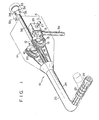
- An endoscope 10 has a control section 11 which has a motor drive unit or electric deflection mechanism 12 serving as an electric deflection mechanism.
- Worm gears 15 and 16 are respectively mounted on the rotating shafts of motors 13 and 14 of the motor drive unit 12.
- Worm wheels 17 and 18 mesh with the worm gears 15 and 16, respectively.
- the worm wheels 17 and 18 are coaxially mounted on wire drums 19 and 20, respectively.
- Angulation wires 21 and 22 are wound around the wire drums 19 and 20, respectively.
- the distal ends of the angulation wires 21 and 22 are secured to a distal end portion 26 of an insertion section 23 through a flexible portion 24 and a deflection portion 25 thereof.
- the distal ends of the angulation wires 21 are vertically secured to oppose each other, so that the insertion section 23 can be vertically deflected.
- the distal ends of the angulation wires 22 are horizontally secured to oppose each other, so that the insertion section 23 can be horizontally deflected.
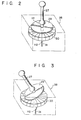
- a single deflection control lever 27 is disposed in the control section 11 to at least partially project outward therefrom and can be manually pivotally inclined by the operator such as a doctor.
- a switch unit 28 is coupled to the deflection control lever 27, which lever may be pivotally inclined in any direction with respect to the neutral position thereof.
- the switch unit 28 comprises a disc 29 which is coaxially mounted on the deflection control lever 27, and a disc 30 which has 16 contact segments a to p radially disposed thereon.
- the disc 29 is spaced apart from the disc 30 by a predetermined distance.
- the deflection control lever 27 is urged by a spring 31 into the neutral position to stand upright when the operator does not apply any force thereto.
- the deflection control lever 27 is rotated about a fulcrum Hl supported by the switch unit 28.
- the spring 31 is disposed in a hole H2 formed in the bottom surface of the switch unit 28 so as to hold the deflection control lever 27 upright.
- the disc 29 is brought into contact with a corresponding contact segment of the disc 30, as shown in Fig. 3.
- the spring 31 is elastically deflected and exerts a restoring force to cause the deflection control lever 27 to be restored to the neutral position.
- an ocular lens 33 in an eyepiece section 32 of the endoscope 10 are arranged an ocular lens 33, and light-emitting diodes (LEDs) 34 to 37 which indicate the deflection direction of the deflection portion 25.
- An image guide 38 which comprises an optical fiber bundle extends from the eyepiece section 32 to the distal end portion 26 of the insertion section 23 through the control section 11.
- a light guide 39 which also comprises an optical fiber bundle extends from the distal end portion 26 to a universal cord (not shown) through the insertion section 23 and the control section 11, and transmits light obtained from a known endoscope light source apparatus (not shown) from the distal end portion 26 to an external space such as the coeliac cavity.
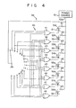
- Figs. 4 to 6 show an electric circuit 39 of a motor drive unit 12 of the endoscope 10 shown in Fig. 1.
- the contact segments a to p and gate input ends are electrically connected by means of wiring conductor 40 having a predetermined pattern.
- the three input ends of a 3-input NOR gate 41 are respectively connected to the contact segments a, b and p.
- the four input ends of a 4-input NOR gate 42 are respectively connected to the contact segments c, d, m and n.
- the three input ends of a 3-input NOR gate 43 are respectively connected to the contact segments d, e and f.
- the four input ends of a 4-input NOR gate 44 are respectively connected to the contact segments b, c, g and h.
- the three input ends of a 3-input NOR gate 45 are respectively connected to the contact segments h, i and j.
- the four input ends of a 4-input NOR gate 46 are respectively connected to the contact segments f, g, k and Q.
- the three input ends of a 3-input NOR gate 47 are respectively connected to the contact segments L, m and n.
- the four input ends of a 4-input NOR gate 48 are respectively connected to the contact segments j, k, o and p.
- the contact segments a to p are arranged in a semi-circular shape in Fig. 4 only for illustrative convenience.
- the contact segments a to p are arranged in a circular shape.
- the input ends of the NOR gates 41 and 48 are also connected to the ground terminal of a power source 70 through respective resistors, but such a connection is not illustrated in Fig. 4.
- the output ends of the NOR gates 41 to 48 are connected to the cathodes of LEDs 51e to 58e of known photocouplers 51 to 58, respectively.
- the anodes of the LEDs 5le to 58e are connected to a VCC terminal 70a of the power source 70 through resistors 61 to 68, respectively.
- the VCC terminal 70a of the power source 70 is connected to the disc 29.
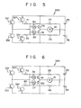
- the collector-emitter paths of phototransistors 51r and 55r of the photocouplers 51 and 55 are respectively connected in series with each other.
- a node between the collector-emitter paths of the phototransistors 51r and the phototransistor 55r is connected to a node between the anode of the LED 34 and the cathode of the LED 35.
- the anode of the LED 34 is connected to the emitter of a phototransistor 52r of the photocoupler 52 through a resistor 71.
- the cathode of the LED 35 is connected to the collector of a phototransistor 56r of the photocoupler 56 through a resistor 72.
- the cathode of the LED 34 and the anode of the LED 35 are connected to the bases of transistors 73 and 74, respectively.
- a node between the emitters of the transistors 73 and 74 is connected to one end of the motor 14.
- a node between DC power sources 75 and 76 is connected to the other end of the motor 14.
- the node between the DC power sources 75 and 76 is connected to the anode of the LED 34 through a resistor 77 and to the cathode of the LED 35 through a resistor 78.
- the positive terminal of the DC power source 75 is connected to the collectors of the transistor 73 and the phototransistors 51r and 52r.
- the negative terminal of the DC power source 76 is connected to the collector of the transistor 74 and to the emitters of the phototransistors 55r and 56r.
- Fig. 6 shows a motor drive circuit 40b which horizontally deflects the deflection portion 25.
- This motor drive circuit has substantially the same arrangement as that shown in Fig. 5.
- resistors 79 and 80, transistors 81 and 82, resistors 85 and 86, and DC power sources 83 and 84 correspond to the resistors 71 and 72, the transistors 73 and 74, the resistors 77 and 78, and the DC power sources 75 and 76, respectively.
- the deflection control lever 27 When the deflection control lever 27 is located in the neutral position, that is, when the operator does not apply any force thereto, the disc 29 does not contact any one of the contact segments a to p.
- the photocouplers 51 to 58 are OFF, and the motors 13 and 14 are OFF.
- the operator moves the deflection control lever 27 in the direction indicated by arrow A in Fig. 1, the disc 29 is brought into contact with the contact segment a.
- the NOR gate 41 goes low, and the LED 51e of the photocoupler 51 goes on.
- the phototransistor 51r shown in Fig. 5 is then rendered conductive.
- the motor 14 is rotated in the forward direction since a current flows through the collector-emitter path of the transistor 73.
- the wire drum 20 is then pivoted in the direction indicated by arrow B.
- the upper wire of the angulation wires 22 is pulled, and the deflection portion 25 is deflected upward, as shown in Fig. 1.
- the deflection state is indicated by the LED 34 which is ON.
- the NOR gates 42 and 44 in Fig. 4 go low, and the photocouplers 52 and 54 are optically coupled so that the phototransistors 52r and 54r (Figs. 5 and 6) are rendered conductive.
- a bias voltage divided by the resistors 71 and 77 is applied across the transistor 73, while a bias voltage divided by the resistors 79 and 85 is applied across the transistor 81.
- Drive currents corresponding to these bias voltages flow through the motors 13 and 14, respectively, so that the motors 13 and 14 are rotated at a speed which is half the normal speed.
- the wire drums 19 and 20 move relatively slowly in the directions indicated by arrows B and C, respectively.
- the deflection portion 25 is deflected in the direction corresponding to 45° with respect to the neutral position. This deflection direction can be confirmed when the LEDs 34 and 36 are ON.
- the deflection portion 25 of the endoscope 10 can be deflected by repeating the above operation, thereby deflecting the distal end portion 26 in the coeliac cavity in the desired direction.
- the operator such as a doctor, operates only the deflection control lever 27 to electrically bring the disc 29 into contact with any one of the contact segments a to p of the disc 30.
- the operator can select a desired mode among the predetermined deflection modes.
- the deflection portion 25 can be electrically deflected in the desired deflection mode. Since the operator needs to operate only the deflection control lever 27, operability of the endoscope 10 can be greatly improved without requiring a complex switching operation.
- the distal end portion 26 of the deflection portion 25 of the endoscope 10 can be bent or deflected inside the coeliac cavity in any direction, thereby greatly improving the precision and effectiveness of the endoscopic therapy. Further, since the operator operates only the deflection control lever 27, erroneous deflection operation can be prevented. The deflection portion 25 may not be undesirably deflected too much and/or may not be unexpectedly deflected in a different direction, thus preventing damage to the body of the patient. Furthermore, safe endoscopic therapy is also guaranteed. The deflection direction may be confirmed by means of the LEDs visually disposed in the field of view of the operator as well as by the position of the deflection control lever.
- Figs. 7 and 8 show an endoscope apparatus according to a second embodiment of the present invention.
- the same reference numerals as used in the first embodiment denote the same parts in the second embodiment, and a detailed description thereof will be omitted.
- An electric deflection mechanism 100 including two reversible motors 108 and 110 is housed in a control section 11 of an endoscope 102.
- wire drums 112 and 114 are mounted on the rotating shafts of the motors 108 and 110, respectively.
- the wire drums 112 and 114 are rotated together with the motors 108 and 110, respectively, in the forward or reverse direction.
- Angulation wires 116 and 118 are looped around the wire drums 112 and 114, respectively.
- the angulation wires 116 and 118 extend through an insertion section 23 and the distal ends thereof are secured to a distal end portion 26 in the same manner as in the first embodiment.
- Potentiometers 120 and 122 are coaxially mounted to the wire drums 112 and 114, respectively.
- the potentiometer 120 has terminals 120a, 120b and 120c, and a slidable contact 120s (Fig. 8) which is operated to drive the motor 108 in the forward or reverse direction in a known manner. Therefore, the output voltage of the potentiometer 120 is changed in accordance with movement of the wire drum 112.
- the potentiometer 122 has the same configuration as the potentiometer 120.
- a deflection control mechanism 124 is disposed in the control section 11 to control deflection operation of the endoscope insertion section 23.
- the deflection control mechanism 124 includes a single deflection control lever 126 which is freely pivotal about its proximal end, and a knob 128 which is attached at the free end of the deflection control lever 126 and extends outside the control section 11 so as to allow the operator to manually operate it.
- the deflection control lever 126 may be manually inclined in any direction including the forward, backward, right and left directions with respect to the neutral position (the upright position with respect to a fulcrum 130) shown in Fig. 7.
- the motors 108 and 110 are driven in accordance with the tilt direction and the tilt angle of the deflection control lever 126.
- the deflection control lever 126 is mounted at its proximal end on the fulcrum 130 and extends through elongated openings 132h and 134h of pivot frames 132 and 134.
- the pivot frames 132 and 134 are disposed perpendicularly to each other and are respectively pivotal about shafts 132r and 134r in arc forms in response to movement of the deflection control lever 126 in a known manner.
- a potentiometer 136 is mounted on the shaft 132r, and a potentiometer 138 is mounted on the shaft 134r.
- the slidable contacts of the potentiometers 136 and 138 move in synchrony with pivotal movement of the pivot frames 132 and 134 to generate output voltages corresponding to the degree of pivotal movement of the pivot frames 132 and 134, respectively.
- Fig. 8 shows the electric circuit 245 which is associated with the deflection operation of the insertion section of the endoscope apparatus according to the second embodiment.
- the potentiometer 138 is connected between the two terminals of a DC power source 146 through terminals 138a and 138c.
- the terminal 138b is connected to the first input end of an operational amplifier 150 through a resistor 148 and to the motor 108 through a feedback resistor 152.
- the potentiometer 120 is connected in parallel with the potentiometer 138.
- the terminal 120b is connected to the second input end of the operational amplifier 150 through the resistor 154.
- the output end of the operational amplifier 150 is connected to a node between the bases of npn and pnp transistors 156 and 158 which together constitute a current amplifier 160.
- the emitters of the transistors 156 and 158 are connected together, and the node thereof is connected to the motor 108.
- Two DC power sources 162 and 164 are connected between the collectors of the transistors 156 and 158.
- the operational amplifier 150 and the current amplifier 160 which comprises the transistors 156 and 158 constitute a servo control circuit 166.
- the motor 110, and the deflection control circuit including the motor 110 and the pivot frame 134 have substantially similar configurations as above, and a detailed description thereof will be omitted to prevent redundancy of the present specification.
- the circuit elements of the servo control circuit 166 to circuit elements of a servo control circuit including the motor 110, the circuit elements of the latter are indicated by corresponding reference numerals having a dash or prime.
- a voltage proportional to the output voltage from the operational amplifier 150 is applied across the motor 108 which is then driven.
- the wire drum 112 is rotated in the direction indicated by arrow E in Fig. 7, and the upper wire of the angulation wires 116 is pulled in the direction indicated by arrow F.
- the distal end of the upper wire which is located in the distal end portion 26 is pulled.
- the deflection portion 25 of the insertion section 23 is deflected upward.
- the slidable contact 120s of the potentiometer 120 coaxially disposed with the wire drum 112 of the motor 108 is moved toward the terminal 120c.
- the terminal voltage V2 (Fig. 8) at the terminal 120b is also increased.
- the output voltage from the operational amplifier 150 is set at substantially 0 V.
- the transistor 158 is turned OFF, and the motor 108 is stopped.
- the terminal voltage V1 of the potentiometer 138 disposed in the deflection control mechanism 124 is changed in accordance with the degree of movement of the deflection control lever 126.
- the motor 108 is also driven in accordance with the degree of movement described above.
- the potentiometer 120 is synchronous with the motor 108 and changes its terminal voltage V2 in accordance with the rotating action of the motor 108.
- the operator operates only the deflection control lever 126 to electrically deflect the deflection portion 25 of the insertion section 23 in the desired direction. Therefore, the operability of the endoscope concerning the deflection operation can be greatly improved, and endoscopic therapy of the coeliac cavity is effectively performed. Furthermore, since the deflection portion 25 can be very precisely deflected in accordance with the electrically detected degree of movement of the deflection control lever 126, the deflection portion will not overrun, thus providing safer endoscopic operation.
- the degree of movement of the deflection control lever is detected by electrically processing output voltages from the potentiometers in the servo control circuit which includes the operational amplifier.
- the electrical detection technique of the degree of movement of the deflection control lever need not be limited to the above technique. The detection technique may vary in accordance with the technical level of the person skilled in the art.
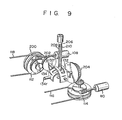
- Figs. 9 and 10 show a modification for detecting the degree of movement of the deflection control lever, wherein pressure-sensitive elements such as piezoelectric rubber portions are adhered to two surfaces of an elastic deflection control lever so as to detect a distortion of the lever on the basis of the outputs from the pressure-sensitive elements.
- spur gears 202 and 204 are respectively mounted on'shafts 132r and 134r of pivot frames 132 and 134.
- the spur gears 202 and 204 are mechanically coupled to the wire drums 112 and 114 which are synchronously driven with the motors 108 and 110 through known gear mechanisms.
- Resistor distortion gauges 208 and 210 which comprise two piezoelectric rubber portions are adhered to the surface of a deflection control lever 206 which comprises an elastic material. The distortion gauges 208 and 210 change their resistances when a compression or tensile force is applied thereto.
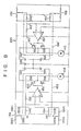
- Fig. 10 is a circuit diagram of a deflection drive circuit 211 of the modification (Fig. 9) which includes the distortion gauge 208, to vertically deflect the deflection portion 25.
- a circuit configuration of a deflection drive circuit which horizontally deflects the deflection portion 25 and which includes the distortion gauge 208 is substantially the same as the deflection drive circuit 211, and a detailed description thereof will be omitted.
- the resistor distortion gauge 208 together with three resistors 212, 214 and 216, constitutes a bridge circuit 218.
- a DC power source 219 is connected between the input ends of the bridge circuit 218.
- One other output end of the bridge circuit 218 is connected to one input end of a differential amplifier 220.
- the output end of the bridge circuit 218 is connected to the first terminal of the motor 108.
- the output end of the differential amplifier 220 is connected, through the resistor 222, to a buffer circuit 224 which comprises transistors 226 and 228 connected in series with each other.
- a common node between the emitters of the transistors 226 and 228 is connected to the second terminal of the motor 108, to the other input end of the differential amplifier 220 through a resistor 230, and to the other output end of the bridge circuit 218 through the resistor 230 and a resistor 232.
- Reference numerals 234 and 236 denote DC power sources, respectively.
- the buffer circuit 224 causes the motor 108 to be driven in the forward or reverse direction in accordance with the potential difference described above, thereby deflecting the deflection portion of the endoscope.
- the buffer circuit 224 causes the motor 108 to be driven in the forward or reverse direction in accordance with the potential difference described above, thereby deflecting the deflection portion of the endoscope.
- the spur gear 202 which meshes with the wire drum 112 is rotated.
- the pivot frame 132 is gradually pivoted so as to push the deflection control lever 206 to eliminate deflection of the deflection control lever 206. Therefore, unless the operator applies further force to the deflection control lever 206, the deflection of the deflection control lever 206 itself is automatically released.
- the bridge circuit 218 is returned to the balanced state since no external force is applied, and the output voltage from the bridge circuit 218 becomes zero.
- the transistors 226 and 228 which constitute the buffer circuit 224 are turned OFF, and the motor 108 is automatically stopped.
- the operator operates only the deflection control lever 206 to electrically deflect the deflection portion of the endoscope.
- the deflection operability of the endoscope is greatly improved in the same manner as in the first and second embodiments, thereby providing safe and efficient endoscopic therapy.
- the degree of actual movement of the deflection control lever 206 is electrically detected by the bridge circuit 218 which includes the distortion gauges so as to deflect the deflection portion in accordance with detected data, highly precise deflection operation can be performed.
- the distal end portion of the insertion section may not unexpectedly abut against the tissue of the coeliac cavity, thus providing safe endoscopic therapy.
- the sixteen contact segments are radially disposed.
- the number of contact segments is not limited to sixteen, but may be more or less than sixteen.
- microswitches may be used in place of the contact segments.
Abstract
Description
- The present invention relates to an endoscope apparatus and, more particularly, to an endoscope apparatus having an electric deflection mechanism for electrically deflecting an insertion section.
- The insertion section of the endoscope is inserted into a body cavity such as a coeliac cavity of a patient and is bent or deflected by an operator, such as a doctor, as needed. An endoscope apparatus is known wherein the insertion section, including a flexible tube, is electrically driven by an electric bending mechanism or electric deflection mechanism in order to improve deflection operability of the insertion section.
- The endoscope has an advantage in that the insertion section thereof is directly inserted in the coeliac cavity such as the stomach and intestines for a specific medical purpose. Therefore, the deflection operation of the insertion section of the endoscope in the coeliac cavity must be as precise as possible to guarantee safe endoscopic therapy and to provide technical precision and effectiveness.
- According to a conventional endoscope apparatus, in order to deflect the distal end portion of the insertion section which is inserted in a coeliac cavity in a desired direction including four directions (upward, downward, right, and left), at least four deflection control switches which are used to deflect the insertion section in the respective four directions are arranged in the endoscope control section. The operator uses a single switch or a combination of switches among the four switches to deflect the distal end portion of the insertion section in the desired direction.
- However, in the conventional endoscope apparatus of the type described above, the switching operation for deflection operation is complex and cumbersome. When the operator, such as a doctor, erroneously presses switches, the insertion section is undesirably deflected in an unexpected direction. Since the insertion section may be deflected too much and/or in an unexpected direction, the distal end portion of the insertion section may touch the tissue of the inner wall of the coeliac cavity. In the worst case, the healthy tissue of the coeliac cavity may be damaged or cut. Since the operability of the control switches for deflecting the insertion section is poor and the rotational frequency of the motor is controlled by the operator, a highly precise and high-speed deflection operation is difficult to perform. As a result, the endoscopic therapy does not sufficiently guarantee technical precision, medical effectiveness, or the safety of the patient.
- It is, therefore, an object of the present invention to provide a new and improved endoscope apparatus wherein easy deflection allows an insertion section of the endoscope apparatus to freely deflect, thereby providing effective therapy and safe endoscopic operation.
- An endoscope apparatus in accordance with the present invention comprises an insertion section properly deflected in a coeliac cavity of a body into which the insertion section is inserted, a control section mechanically coupled to the insertion section, a motor device which is provided-in the control section and which generates rotational torque used for deflecting the in ertion section, a deflection mechanism, and a control device. The deflection mechanism is provided in the insertion section and the control section and is mechanically coupled to the distal end portion of the insertion section and to the motor device. The deflection mechanism suitably deflects the insertion section in accordance with the rotational torque generated by the motor device. The control device includes a single deflection control lever which extends from the insertion section to the outside of the apparatus and is operated to be arbitrarily inclined in any direction with respect to the neutral position thereof. The control device is disposed in the control section and is electrically connected to the motor device therein. Electric power supplied to the device is varied in accordance with a tilt direction of the deflection control lever selected by the operator. The insertion section is then bent or deflected in the desired direction in accordance with the tilt direction of the deflection control lever. Therefore, the distal end portion of the insertion section is arbitrarily and very precisely deflected in the desired direction under the control of the operator who manually operates only the deflection control lever.
- The present invention is best understood by reference to the accompanying drawings, in which:
- Fig. 1 is a schematic perspective view showing the overall construction of an endoscope apparatus according to a first embodiment of the present invention;
- Fig. 2 is a partial perspective view showing the deflection control lever disposed in the endoscope apparatus shown in Fig. 1 in a neutral position;
- Fig. 3 is a perspective view showing the deflection control section when the deflection control lever shown in Fig. 2 is inclined by the operator;
- Fig. 4 is a circuit diagram of an electric deflection mechanism of the endoscope apparatus shown in Fig. 1;
- Fig. 5 is a circuit diagram showing a motor as a deflection drive source and its driver circuit;
- Fig. 6 is a circuit diagram showing another motor as a deflection drive source and its driver circuit;
- Fig. 7 is a schematic perspective view showing the overall construction of an endoscope apparatus according to a second embodiment of the present invention;
- Fig. 8 is a circuit diagram of an electric deflection mechanism of the endoscope apparatus shown in Fig. 7;
- Fig. 9 is a partial perspective view schematically showing a modification of the main part of the electric deflection mechanism; and
- Fig. 10 is a circuit diagram of the electric deflection mechanism shown in Fig. 9.
- Referring now to Fig. 1, there is illustrated an endoscope apparatus in accordance with the first embodiment of the present invention. An
endoscope 10 has acontrol section 11 which has a motor drive unit orelectric deflection mechanism 12 serving as an electric deflection mechanism.Worm gears motors motor drive unit 12.Worm wheels 17 and 18 mesh with theworm gears worm wheels 17 and 18 are coaxially mounted onwire drums Angulation wires 21 and 22 are wound around thewire drums angulation wires 21 and 22 are secured to adistal end portion 26 of aninsertion section 23 through aflexible portion 24 and adeflection portion 25 thereof. In this case, the distal ends of theangulation wires 21 are vertically secured to oppose each other, so that theinsertion section 23 can be vertically deflected. The distal ends of the angulation wires 22 are horizontally secured to oppose each other, so that theinsertion section 23 can be horizontally deflected. - A single
deflection control lever 27 is disposed in thecontrol section 11 to at least partially project outward therefrom and can be manually pivotally inclined by the operator such as a doctor. Aswitch unit 28 is coupled to thedeflection control lever 27, which lever may be pivotally inclined in any direction with respect to the neutral position thereof. As shown in Fig. 2, theswitch unit 28 comprises adisc 29 which is coaxially mounted on thedeflection control lever 27, and adisc 30 which has 16 contact segments a to p radially disposed thereon. Thedisc 29 is spaced apart from thedisc 30 by a predetermined distance. Thedeflection control lever 27 is urged by aspring 31 into the neutral position to stand upright when the operator does not apply any force thereto. Thedeflection control lever 27 is rotated about a fulcrum Hl supported by theswitch unit 28. Normally, thespring 31 is disposed in a hole H2 formed in the bottom surface of theswitch unit 28 so as to hold thedeflection control lever 27 upright. When an external force is applied to thedeflection control lever 27 by the operator, thedisc 29 is brought into contact with a corresponding contact segment of thedisc 30, as shown in Fig. 3. At this time, since one end position of thespring 31 is defined by the hole H2, thespring 31 is elastically deflected and exerts a restoring force to cause thedeflection control lever 27 to be restored to the neutral position. - Referring to Fig. 1 again, in an eyepiece section 32 of the
endoscope 10 are arranged anocular lens 33, and light-emitting diodes (LEDs) 34 to 37 which indicate the deflection direction of thedeflection portion 25. Animage guide 38 which comprises an optical fiber bundle extends from the eyepiece section 32 to thedistal end portion 26 of theinsertion section 23 through thecontrol section 11. Alight guide 39 which also comprises an optical fiber bundle extends from thedistal end portion 26 to a universal cord (not shown) through theinsertion section 23 and thecontrol section 11, and transmits light obtained from a known endoscope light source apparatus (not shown) from thedistal end portion 26 to an external space such as the coeliac cavity. - Figs. 4 to 6 show an
electric circuit 39 of amotor drive unit 12 of theendoscope 10 shown in Fig. 1. The contact segments a to p and gate input ends are electrically connected by means ofwiring conductor 40 having a predetermined pattern. Referring to Fig. 4, the three input ends of a 3-input NOR gate 41 are respectively connected to the contact segments a, b and p. The four input ends of a 4-input NOR gate 42 are respectively connected to the contact segments c, d, m and n. The three input ends of a 3-input NOR gate 43 are respectively connected to the contact segments d, e and f. The four input ends of a 4-input NOR gate 44 are respectively connected to the contact segments b, c, g and h. The three input ends of a 3-input NOR gate 45 are respectively connected to the contact segments h, i and j. The four input ends of a 4-input NOR gate 46 are respectively connected to the contact segments f, g, k and Q. The three input ends of a 3-input NOR gate 47 are respectively connected to the contact segments L, m and n. Finally, the four input ends of a 4-input NOR gate 48 are respectively connected to the contact segments j, k, o and p. The contact segments a to p are arranged in a semi-circular shape in Fig. 4 only for illustrative convenience. However, in practice, the contact segments a to p are arranged in a circular shape. The input ends of the NORgates power source 70 through respective resistors, but such a connection is not illustrated in Fig. 4. The output ends of the NORgates 41 to 48 are connected to the cathodes ofLEDs 51e to 58e of knownphotocouplers 51 to 58, respectively. The anodes of the LEDs 5le to 58e are connected to a VCC terminal 70a of thepower source 70 throughresistors 61 to 68, respectively. The VCC terminal 70a of thepower source 70 is connected to thedisc 29. - In the motor drive circuit 40a for vertically deflecting the
deflection portion 25, as shown in Fig. 5, the collector-emitter paths ofphototransistors 51r and 55r of thephotocouplers phototransistor 55r is connected to a node between the anode of theLED 34 and the cathode of theLED 35. The anode of theLED 34 is connected to the emitter of aphototransistor 52r of thephotocoupler 52 through aresistor 71. Similarly, the cathode of theLED 35 is connected to the collector of aphototransistor 56r of thephotocoupler 56 through aresistor 72. The cathode of theLED 34 and the anode of theLED 35 are connected to the bases oftransistors transistors motor 14. A node betweenDC power sources motor 14. The node between theDC power sources LED 34 through aresistor 77 and to the cathode of theLED 35 through aresistor 78. The positive terminal of theDC power source 75 is connected to the collectors of thetransistor 73 and thephototransistors 51r and 52r. The negative terminal of theDC power source 76 is connected to the collector of thetransistor 74 and to the emitters of thephototransistors - Fig. 6 shows a motor drive circuit 40b which horizontally deflects the
deflection portion 25. This motor drive circuit has substantially the same arrangement as that shown in Fig. 5. Referring to Fig. 6,resistors transistors resistors DC power sources resistors transistors resistors DC power sources - The mode of operation of the endoscope apparatus according to the first embodiment of the present invention will be described. When the
deflection control lever 27 is located in the neutral position, that is, when the operator does not apply any force thereto, thedisc 29 does not contact any one of the contact segments a to p. Thephotocouplers 51 to 58 are OFF, and themotors deflection control lever 27 in the direction indicated by arrow A in Fig. 1, thedisc 29 is brought into contact with the contact segment a. The NORgate 41 goes low, and theLED 51e of thephotocoupler 51 goes on. The phototransistor 51r shown in Fig. 5 is then rendered conductive. A current flows in the base of thetransistor 73 through the phototransistor 51r and theLED 34. As a result, thetransistor 73 is rendered conductive. Themotor 14 is rotated in the forward direction since a current flows through the collector-emitter path of thetransistor 73. Upon rotation of themotor 14 in the forward direction, thewire drum 20 is then pivoted in the direction indicated by arrow B. The upper wire of the angulation wires 22 is pulled, and thedeflection portion 25 is deflected upward, as shown in Fig. 1. The deflection state is indicated by theLED 34 which is ON. When thedeflection portion 25 has been deflected into the desired position, the opera- tor releases thedeflection control lever 27. Themotor 14 is then stopped and the deflection position of thedeflection portion 25 is held in the desired position. - When the operator then operates the
deflection control lever 27 to bring thedisc 29 into contact with the contact segment c, for example, the NORgates photocouplers phototransistors resistors transistor 73, while a bias voltage divided by theresistors transistor 81. Drive currents corresponding to these bias voltages flow through themotors motors deflection portion 25 is deflected in the direction corresponding to 45° with respect to the neutral position. This deflection direction can be confirmed when theLEDs - The
deflection portion 25 of theendoscope 10 can be deflected by repeating the above operation, thereby deflecting thedistal end portion 26 in the coeliac cavity in the desired direction. The operator, such as a doctor, operates only thedeflection control lever 27 to electrically bring thedisc 29 into contact with any one of the contact segments a to p of thedisc 30. Thus, the operator can select a desired mode among the predetermined deflection modes. As a result, thedeflection portion 25 can be electrically deflected in the desired deflection mode. Since the operator needs to operate only thedeflection control lever 27, operability of theendoscope 10 can be greatly improved without requiring a complex switching operation. Thedistal end portion 26 of thedeflection portion 25 of theendoscope 10 can be bent or deflected inside the coeliac cavity in any direction, thereby greatly improving the precision and effectiveness of the endoscopic therapy. Further, since the operator operates only thedeflection control lever 27, erroneous deflection operation can be prevented. Thedeflection portion 25 may not be undesirably deflected too much and/or may not be unexpectedly deflected in a different direction, thus preventing damage to the body of the patient. Furthermore, safe endoscopic therapy is also guaranteed. The deflection direction may be confirmed by means of the LEDs visually disposed in the field of view of the operator as well as by the position of the deflection control lever. - Figs. 7 and 8 show an endoscope apparatus according to a second embodiment of the present invention. The same reference numerals as used in the first embodiment denote the same parts in the second embodiment, and a detailed description thereof will be omitted.
- An
electric deflection mechanism 100 including tworeversible motors control section 11 of anendoscope 102. According to suchelectric deflection mechanism 100, wire drums 112 and 114 are mounted on the rotating shafts of themotors motors Angulation wires angulation wires insertion section 23 and the distal ends thereof are secured to adistal end portion 26 in the same manner as in the first embodiment. -
Potentiometers potentiometer 120 hasterminals 120a, 120b and 120c, and a slidable contact 120s (Fig. 8) which is operated to drive themotor 108 in the forward or reverse direction in a known manner. Therefore, the output voltage of thepotentiometer 120 is changed in accordance with movement of thewire drum 112. Thepotentiometer 122 has the same configuration as thepotentiometer 120. - A
deflection control mechanism 124 is disposed in thecontrol section 11 to control deflection operation of theendoscope insertion section 23. Thedeflection control mechanism 124 includes a singledeflection control lever 126 which is freely pivotal about its proximal end, and aknob 128 which is attached at the free end of thedeflection control lever 126 and extends outside thecontrol section 11 so as to allow the operator to manually operate it. Thedeflection control lever 126 may be manually inclined in any direction including the forward, backward, right and left directions with respect to the neutral position (the upright position with respect to a fulcrum 130) shown in Fig. 7. Themotors deflection control lever 126. - The
deflection control lever 126 is mounted at its proximal end on thefulcrum 130 and extends throughelongated openings shafts deflection control lever 126 in a known manner. Apotentiometer 136 is mounted on theshaft 132r, and apotentiometer 138 is mounted on theshaft 134r. The slidable contacts of thepotentiometers - Fig. 8 shows the
electric circuit 245 which is associated with the deflection operation of the insertion section of the endoscope apparatus according to the second embodiment. Thepotentiometer 138 is connected between the two terminals of a DC power source 146 through terminals 138a and 138c. The terminal 138b is connected to the first input end of anoperational amplifier 150 through aresistor 148 and to themotor 108 through afeedback resistor 152. Thepotentiometer 120 is connected in parallel with thepotentiometer 138. The terminal 120b is connected to the second input end of theoperational amplifier 150 through theresistor 154. The output end of theoperational amplifier 150 is connected to a node between the bases of npn andpnp transistors current amplifier 160. The emitters of thetransistors motor 108. TwoDC power sources 162 and 164 are connected between the collectors of thetransistors operational amplifier 150 and thecurrent amplifier 160 which comprises thetransistors servo control circuit 166. - The
motor 110, and the deflection control circuit including themotor 110 and thepivot frame 134, have substantially similar configurations as above, and a detailed description thereof will be omitted to prevent redundancy of the present specification. In order to correspond circuit elements of theservo control circuit 166 to circuit elements of a servo control circuit including themotor 110, the circuit elements of the latter are indicated by corresponding reference numerals having a dash or prime. - The mode of operation of the endoscope apparatus according to the second embodiment will be described hereinafter. When the operator moves the
deflection control lever 126 in the direction indicated by arrow D in Fig. 7, thepivot frame 132 is urged by thedeflection control lever 126 and is moved in the direction indicated by arrow D. At the same time, a slidable contact 138s of thepotentiometer 138 is moved toward the terminal 138c in accordance with the degree of movement of thepivot frame 132. Therefore, a terminal voltage Vl at the terminal 138b is increased and is higher than a terminal voltage V2 at the terminal 120b of thepotentiometer 120. As a result, a negative voltage appears at the output end of theoperational amplifier 150, and thetransistor 158 is rendered conductive. A voltage proportional to the output voltage from theoperational amplifier 150 is applied across themotor 108 which is then driven. Thewire drum 112 is rotated in the direction indicated by arrow E in Fig. 7, and the upper wire of theangulation wires 116 is pulled in the direction indicated by arrow F. The distal end of the upper wire which is located in thedistal end portion 26 is pulled. As a result, thedeflection portion 25 of theinsertion section 23 is deflected upward. At this time, the slidable contact 120s of thepotentiometer 120 coaxially disposed with thewire drum 112 of themotor 108 is moved toward the terminal 120c. Thus, the terminal voltage V2 (Fig. 8) at the terminal 120b is also increased. - When the terminal voltage V2 at the terminal 120b becomes substantially equal to the terminal voltage V1, the output voltage from the
operational amplifier 150 is set at substantially 0 V. Thetransistor 158 is turned OFF, and themotor 108 is stopped. In this manner, the terminal voltage V1 of thepotentiometer 138 disposed in thedeflection control mechanism 124 is changed in accordance with the degree of movement of thedeflection control lever 126. Themotor 108 is also driven in accordance with the degree of movement described above. At this time, thepotentiometer 120 is synchronous with themotor 108 and changes its terminal voltage V2 in accordance with the rotating action of themotor 108. When a difference between the terminal voltages V1 and V2 becomes substantially zero, themotor 108 is immediately stopped. - In the second embodiment described above, the operator operates only the
deflection control lever 126 to electrically deflect thedeflection portion 25 of theinsertion section 23 in the desired direction. Therefore, the operability of the endoscope concerning the deflection operation can be greatly improved, and endoscopic therapy of the coeliac cavity is effectively performed. Furthermore, since thedeflection portion 25 can be very precisely deflected in accordance with the electrically detected degree of movement of thedeflection control lever 126, the deflection portion will not overrun, thus providing safer endoscopic operation. - Although the present invention has been shown and described with respect to particular embodiments, nevertheless, various changes and modifications which are obvious to a person skilled in the art to which the invention pertains are deemed to lie within the spirit, scope and contemplation of the invention.
- In the second embodiment, the degree of movement of the deflection control lever is detected by electrically processing output voltages from the potentiometers in the servo control circuit which includes the operational amplifier. However, the electrical detection technique of the degree of movement of the deflection control lever need not be limited to the above technique. The detection technique may vary in accordance with the technical level of the person skilled in the art.
- Figs. 9 and 10 show a modification for detecting the degree of movement of the deflection control lever, wherein pressure-sensitive elements such as piezoelectric rubber portions are adhered to two surfaces of an elastic deflection control lever so as to detect a distortion of the lever on the basis of the outputs from the pressure-sensitive elements.
- In an
electric deflection mechanism 200 shown in Fig. 9, spur gears 202 and 204 are respectively mounted on'shafts 132r and 134r of pivot frames 132 and 134. The spur gears 202 and 204 are mechanically coupled to the wire drums 112 and 114 which are synchronously driven with themotors deflection control lever 206 which comprises an elastic material. The distortion gauges 208 and 210 change their resistances when a compression or tensile force is applied thereto. - Fig. 10 is a circuit diagram of a
deflection drive circuit 211 of the modification (Fig. 9) which includes thedistortion gauge 208, to vertically deflect thedeflection portion 25. A circuit configuration of a deflection drive circuit which horizontally deflects thedeflection portion 25 and which includes thedistortion gauge 208 is substantially the same as thedeflection drive circuit 211, and a detailed description thereof will be omitted. Referring to Fig. 10, theresistor distortion gauge 208, together with threeresistors bridge circuit 218. ADC power source 219 is connected between the input ends of thebridge circuit 218. One other output end of thebridge circuit 218 is connected to one input end of adifferential amplifier 220. The output end of thebridge circuit 218 is connected to the first terminal of themotor 108. The output end of thedifferential amplifier 220 is connected, through the resistor 222, to abuffer circuit 224 which comprisestransistors transistors motor 108, to the other input end of thedifferential amplifier 220 through aresistor 230, and to the other output end of thebridge circuit 218 through theresistor 230 and aresistor 232.Reference numerals - In the modification having the configuration described above, when the
deflection control lever 206 is not deflected, thebridge circuit 218 is balanced. Therefore, the output voltage from thebridge circuit 218 is zero. - When the operator deflects the
deflection control lever 206, a compression or tensile stress is applied to thedistortion gauge 208. The resistance of thedistortion gauge 208 is changed in accordance with the compression or tensile stress. As a result, a potential difference which corresponds to a change in resistance of thedistortion gauge 208 appears between the output ends of thebridge circuit 218. Thebuffer circuit 224 causes themotor 108 to be driven in the forward or reverse direction in accordance with the potential difference described above, thereby deflecting the deflection portion of the endoscope. - When the
wire drum 112 is rotated upon deflection of the deflection portion of the endoscope, thespur gear 202 which meshes with thewire drum 112 is rotated. Upon rotation of thegear 202, thepivot frame 132 is gradually pivoted so as to push thedeflection control lever 206 to eliminate deflection of thedeflection control lever 206. Therefore, unless theoperator bridge circuit 218 through theresistor 230 and aresistor 232.Reference numerals - In the modification having the configuration described above, when the
deflection control lever 206 is not deflected, thebridge circuit 218 is balanced. Therefore, the output voltage from thebridge circuit 218 is zero. - When the operator deflects the
deflection control lever 206, a compression or tensile stress is applied to thedistortion gauge 208. The resistance of thedistortion gauge 208 is changed in accordance with the compression or tensile stress. As a result, a potential difference which corresponds to a change in resistance of thedistortion gauge 208 appears between the output ends of thebridge circuit 218. Thebuffer circuit 224 causes themotor 108 to be driven in the forward or reverse direction in accordance with the potential difference described above, thereby deflecting the deflection portion of the endoscope. - When the
wire drum 112 is rotated upon deflection of the deflection portion of the endoscope, thespur gear 202 which meshes with thewire drum 112 is rotated. Upon rotation of thegear 202, thepivot frame 132 is gradually pivoted so as to push thedeflection control lever 206 to eliminate deflection of thedeflection control lever 206. Therefore, unless the operator applies further force to thedeflection control lever 206, the deflection of thedeflection control lever 206 itself is automatically released. At this time, thebridge circuit 218 is returned to the balanced state since no external force is applied, and the output voltage from thebridge circuit 218 becomes zero. Thetransistors buffer circuit 224 are turned OFF, and themotor 108 is automatically stopped. In this manner, the operator operates only thedeflection control lever 206 to electrically deflect the deflection portion of the endoscope. The deflection operability of the endoscope is greatly improved in the same manner as in the first and second embodiments, thereby providing safe and efficient endoscopic therapy. Further, since the degree of actual movement of thedeflection control lever 206 is electrically detected by thebridge circuit 218 which includes the distortion gauges so as to deflect the deflection portion in accordance with detected data, highly precise deflection operation can be performed. The distal end portion of the insertion section may not unexpectedly abut against the tissue of the coeliac cavity, thus providing safe endoscopic therapy. - In the first embodiment shown in Figs. 1 to 6, the sixteen contact segments are radially disposed. However, the number of contact segments is not limited to sixteen, but may be more or less than sixteen. Furthermore, microswitches may be used in place of the contact segments.
Claims (11)
Priority Applications (1)
| Application Number | Priority Date | Filing Date | Title |
|---|---|---|---|
| AT82110131T ATE25812T1 (en) | 1981-11-04 | 1982-11-03 | ENDOSCOPIC DEVICE WITH ELECTRIC BENDING MECHANISM. |
Applications Claiming Priority (2)
| Application Number | Priority Date | Filing Date | Title |
|---|---|---|---|
| JP176917/81 | 1981-11-04 | ||
| JP56176917A JPS5878639A (en) | 1981-11-04 | 1981-11-04 | Endoscope |
Publications (2)
| Publication Number | Publication Date |
|---|---|
| EP0079525A1 true EP0079525A1 (en) | 1983-05-25 |
| EP0079525B1 EP0079525B1 (en) | 1987-03-11 |
Family
ID=16022016
Family Applications (1)
| Application Number | Title | Priority Date | Filing Date |
|---|---|---|---|
| EP82110131A Expired EP0079525B1 (en) | 1981-11-04 | 1982-11-03 | Endoscope apparatus with electric deflection mechanism |
Country Status (5)
| Country | Link |
|---|---|
| US (1) | US4503842A (en) |
| EP (1) | EP0079525B1 (en) |
| JP (1) | JPS5878639A (en) |
| AT (1) | ATE25812T1 (en) |
| DE (1) | DE3275624D1 (en) |
Cited By (14)
| Publication number | Priority date | Publication date | Assignee | Title |
|---|---|---|---|---|
| US4621618A (en) * | 1984-02-28 | 1986-11-11 | Olympus Optical Company, Ltd. | Dual viewing and control apparatus for endoscope |
| WO1993007808A1 (en) * | 1991-10-25 | 1993-04-29 | Interspec, Inc. | Ultrasonic probe assembly |
| DE4136861A1 (en) * | 1991-11-11 | 1993-05-13 | Kernforschungsz Karlsruhe | Controllable surgical instrument within trocar for min. invasive surgery - has manipulating and insertion parts, flexible part connected to end of insertion part which is movable and controllable, and effector fitted to flexible part |
| EP0543738A1 (en) * | 1991-11-22 | 1993-05-26 | Welch Allyn, Inc. | Detachable servo actuated insertion tube for borescope or endoscope |
| EP0587506A1 (en) * | 1992-09-11 | 1994-03-16 | Welch Allyn, Inc. | Control mechanism for steerable elongated probe |
| US5450851A (en) * | 1994-05-25 | 1995-09-19 | Advanced Technology Laboratories, Inc. | Ultrasonic probe assembly |
| US5658238A (en) * | 1992-02-25 | 1997-08-19 | Olympus Optical Co., Ltd. | Endoscope apparatus capable of being switched to a mode in which a curvature operating lever is returned and to a mode in which the curvature operating lever is not returned |
| EP1839552A1 (en) * | 2005-01-17 | 2007-10-03 | Olympus Corporation | Electric bending endoscope device |
| FR2907918A1 (en) * | 2006-10-31 | 2008-05-02 | Tokendo Soc Par Actions Simpli | Videoendoscope for industry-oriented endoscopy application, has powered device housed in control handle below visual display unit and including two motors having coaxial shafts around which two cables are driven |
| CN102813498A (en) * | 2012-09-10 | 2012-12-12 | 华东理工大学 | Endoscopic bending angle control handle controlled by one hand |
| CN103799960A (en) * | 2014-01-28 | 2014-05-21 | 河南科技大学 | Bendable and stretchable bladder endoscope |
| EP3375479A1 (en) * | 2007-05-18 | 2018-09-19 | Boston Scientific Scimed, Inc. | Drive systems and methods of use |
| EP2967281B1 (en) * | 2013-03-11 | 2019-03-06 | Boston Scientific Scimed, Inc. | Deflection mechanism |
| EP3598932A3 (en) * | 2018-05-18 | 2020-04-22 | Verathon, Inc. | Endoscope system with a control wheel assembly coupled to pull wires |
Families Citing this family (499)
| Publication number | Priority date | Publication date | Assignee | Title |
|---|---|---|---|---|
| JPS58160002U (en) * | 1982-04-20 | 1983-10-25 | 株式会社町田製作所 | Endoscope head bending device |
| US4721099A (en) * | 1985-10-30 | 1988-01-26 | Kabushiki Kaisha Machida Seisakusho | Operating mechanism for bendable section of endoscope |
| JPH0336321Y2 (en) * | 1986-04-04 | 1991-08-01 | ||
| US4688555A (en) * | 1986-04-25 | 1987-08-25 | Circon Corporation | Endoscope with cable compensating mechanism |
| DE3734979A1 (en) * | 1986-10-16 | 1988-04-28 | Olympus Optical Co | ENDOSCOPE |
| US4753223A (en) * | 1986-11-07 | 1988-06-28 | Bremer Paul W | System for controlling shape and direction of a catheter, cannula, electrode, endoscope or similar article |
| US4838859A (en) * | 1987-05-19 | 1989-06-13 | Steve Strassmann | Steerable catheter |
| US5060632A (en) * | 1989-09-05 | 1991-10-29 | Olympus Optical Co., Ltd. | Endoscope apparatus |
| JP3065702B2 (en) * | 1991-04-23 | 2000-07-17 | オリンパス光学工業株式会社 | Endoscope system |
| US5469840A (en) * | 1991-12-10 | 1995-11-28 | Olympus Optical, Ltd. | Electromotive warping type endoscope with velocity control |
| US5350355A (en) * | 1992-02-14 | 1994-09-27 | Automated Medical Instruments, Inc. | Automated surgical instrument |
| US5626595A (en) * | 1992-02-14 | 1997-05-06 | Automated Medical Instruments, Inc. | Automated surgical instrument |
| US5549542A (en) * | 1992-11-17 | 1996-08-27 | Life Medical Technologies, Inc. | Deflectable endoscope |
| US5472017A (en) * | 1992-11-17 | 1995-12-05 | Life Medical Technologies, Inc. | Deflectable catheter |
| US5352237A (en) * | 1993-02-08 | 1994-10-04 | United States Surgical Corporation | Endoscopic instrument including a handle having a flywheel mechanism |
| US5373317B1 (en) * | 1993-05-28 | 2000-11-21 | Welch Allyn Inc | Control and display section for borescope or endoscope |
| CN1132469A (en) * | 1993-08-30 | 1996-10-02 | Stm医疗技术施塔恩贝格有限公司 | Endoscope with a movable frontal end area |
| US5632432A (en) * | 1994-12-19 | 1997-05-27 | Ethicon Endo-Surgery, Inc. | Surgical instrument |
| US5741320A (en) * | 1995-05-02 | 1998-04-21 | Heart Rhythm Technologies, Inc. | Catheter control system having a pulley |
| US5681280A (en) * | 1995-05-02 | 1997-10-28 | Heart Rhythm Technologies, Inc. | Catheter control system |
| US5666970A (en) * | 1995-05-02 | 1997-09-16 | Heart Rhythm Technologies, Inc. | Locking mechanism for catheters |
| US5752644A (en) * | 1995-07-11 | 1998-05-19 | United States Surgical Corporation | Disposable loading unit for surgical stapler |
| USRE38708E1 (en) | 1995-07-11 | 2005-03-01 | United States Surgical Corporation | Disposable loading unit for surgical stapler |
| FR2740688B1 (en) * | 1995-11-07 | 1997-12-12 | Tokendo Sarl | FLEXIBLE VIDEOENDOSCOPIC PROBE WITH MOTORIZED CONTROL HANDLE |
| US6236876B1 (en) * | 1996-08-30 | 2001-05-22 | The Whitaker Corporation | Navigable probe and motor control apparatus |
| DE19758596B4 (en) * | 1996-11-18 | 2005-07-07 | Olympus Corporation | Endoscope with elongated introduction region and tip region on distal side of this - has bending mechanism for bending curved tip region of introduction section by which region seen on tip side from curving or bending region does not flutter |
| US6371907B1 (en) * | 1996-11-18 | 2002-04-16 | Olympus Optical Co., Ltd. | Endoscope apparatus driving manipulation wires with drive motor in drum portion |
| US5967997A (en) * | 1998-04-30 | 1999-10-19 | Symbiosis Corporation | Endoscopic surgical instrument with deflectable and rotatable distal end |
| US6171235B1 (en) * | 1998-05-29 | 2001-01-09 | Circon Corporation | Flexible pressure resistant cover for the articulation system of a medical instrument |
| US6984203B2 (en) * | 2000-04-03 | 2006-01-10 | Neoguide Systems, Inc. | Endoscope with adjacently positioned guiding apparatus |
| US6858005B2 (en) | 2000-04-03 | 2005-02-22 | Neo Guide Systems, Inc. | Tendon-driven endoscope and methods of insertion |
| US6610007B2 (en) * | 2000-04-03 | 2003-08-26 | Neoguide Systems, Inc. | Steerable segmented endoscope and method of insertion |
| US8517923B2 (en) * | 2000-04-03 | 2013-08-27 | Intuitive Surgical Operations, Inc. | Apparatus and methods for facilitating treatment of tissue via improved delivery of energy based and non-energy based modalities |
| US6468203B2 (en) * | 2000-04-03 | 2002-10-22 | Neoguide Systems, Inc. | Steerable endoscope and improved method of insertion |
| US20050085693A1 (en) * | 2000-04-03 | 2005-04-21 | Amir Belson | Activated polymer articulated instruments and methods of insertion |
| US6800056B2 (en) | 2000-04-03 | 2004-10-05 | Neoguide Systems, Inc. | Endoscope with guiding apparatus |
| US8888688B2 (en) | 2000-04-03 | 2014-11-18 | Intuitive Surgical Operations, Inc. | Connector device for a controllable instrument |
| US6974411B2 (en) * | 2000-04-03 | 2005-12-13 | Neoguide Systems, Inc. | Endoscope with single step guiding apparatus |
| US6837846B2 (en) * | 2000-04-03 | 2005-01-04 | Neo Guide Systems, Inc. | Endoscope having a guide tube |
| US6793622B2 (en) * | 2001-09-05 | 2004-09-21 | Olympus Optical Co., Ltd. | Electric bending endoscope |
| US6835173B2 (en) * | 2001-10-05 | 2004-12-28 | Scimed Life Systems, Inc. | Robotic endoscope |
| US6770027B2 (en) | 2001-10-05 | 2004-08-03 | Scimed Life Systems, Inc. | Robotic endoscope with wireless interface |
| CN1764416A (en) | 2002-01-09 | 2006-04-26 | 新引导系统公司 | Apparatus and method for endoscopic colectomy |
| JP2005514144A (en) * | 2002-01-09 | 2005-05-19 | ネオガイド システムズ, インコーポレイテッド | Apparatus and method for spectroscopic examination of the colon |
| US20040193016A1 (en) * | 2002-06-17 | 2004-09-30 | Thomas Root | Endoscopic delivery system for the non-destructive testing and evaluation of remote flaws |
| US6679836B2 (en) | 2002-06-21 | 2004-01-20 | Scimed Life Systems, Inc. | Universal programmable guide catheter |
| US20040068161A1 (en) * | 2002-10-02 | 2004-04-08 | Couvillon Lucien Alfred | Thrombolysis catheter |
| US20050129108A1 (en) * | 2003-01-29 | 2005-06-16 | Everest Vit, Inc. | Remote video inspection system |
| US8882657B2 (en) | 2003-03-07 | 2014-11-11 | Intuitive Surgical Operations, Inc. | Instrument having radio frequency identification systems and methods for use |
| US7578786B2 (en) | 2003-04-01 | 2009-08-25 | Boston Scientific Scimed, Inc. | Video endoscope |
| US8118732B2 (en) | 2003-04-01 | 2012-02-21 | Boston Scientific Scimed, Inc. | Force feedback control system for video endoscope |
| US7591783B2 (en) * | 2003-04-01 | 2009-09-22 | Boston Scientific Scimed, Inc. | Articulation joint for video endoscope |
| US20040199052A1 (en) | 2003-04-01 | 2004-10-07 | Scimed Life Systems, Inc. | Endoscopic imaging system |
| US20050245789A1 (en) | 2003-04-01 | 2005-11-03 | Boston Scientific Scimed, Inc. | Fluid manifold for endoscope system |
| US20070084897A1 (en) | 2003-05-20 | 2007-04-19 | Shelton Frederick E Iv | Articulating surgical stapling instrument incorporating a two-piece e-beam firing mechanism |
| US9060770B2 (en) | 2003-05-20 | 2015-06-23 | Ethicon Endo-Surgery, Inc. | Robotically-driven surgical instrument with E-beam driver |
| US8365633B2 (en) * | 2003-05-21 | 2013-02-05 | The Johns Hopkins University | Devices, systems and methods for minimally invasive surgery of the throat and other portions of mammalian body |
| US7134993B2 (en) * | 2004-01-29 | 2006-11-14 | Ge Inspection Technologies, Lp | Method and apparatus for improving the operation of a remote viewing device by changing the calibration settings of its articulation servos |
| US20050171467A1 (en) * | 2004-01-30 | 2005-08-04 | Jaime Landman | Multiple function surgical device |
| US7744619B2 (en) * | 2004-02-24 | 2010-06-29 | Boston Scientific Scimed, Inc. | Rotatable catheter assembly |
| US7922740B2 (en) | 2004-02-24 | 2011-04-12 | Boston Scientific Scimed, Inc. | Rotatable catheter assembly |
| JP4468721B2 (en) * | 2004-03-16 | 2010-05-26 | オリンパス株式会社 | Endoscopic treatment instrument system |
| KR100617974B1 (en) * | 2004-04-22 | 2006-08-31 | 한국과학기술원 | Command-following laparoscopic system |
| US8215531B2 (en) | 2004-07-28 | 2012-07-10 | Ethicon Endo-Surgery, Inc. | Surgical stapling instrument having a medical substance dispenser |
| US11896225B2 (en) | 2004-07-28 | 2024-02-13 | Cilag Gmbh International | Staple cartridge comprising a pan |
| US10342452B2 (en) | 2004-07-29 | 2019-07-09 | Medtronic Xomed, Inc. | Stimulator handpiece for an evoked potential monitoring system |
| WO2006039522A2 (en) | 2004-09-30 | 2006-04-13 | Boston Scientific Scimed, Inc. | Adapter for use with digital imaging medical device |
| US8083671B2 (en) | 2004-09-30 | 2011-12-27 | Boston Scientific Scimed, Inc. | Fluid delivery system for use with an endoscope |
| US7479106B2 (en) * | 2004-09-30 | 2009-01-20 | Boston Scientific Scimed, Inc. | Automated control of irrigation and aspiration in a single-use endoscope |
| US7597662B2 (en) | 2004-09-30 | 2009-10-06 | Boston Scientific Scimed, Inc. | Multi-fluid delivery system |
| US7896803B2 (en) * | 2005-02-14 | 2011-03-01 | Karl Storz Imaging, Inc. | Variable direction of view instrument with on-board actuators |
| US7956887B2 (en) * | 2005-02-17 | 2011-06-07 | Karl Storz Imaging, Inc. | Image orienting coupling assembly |
| US20060235457A1 (en) * | 2005-04-15 | 2006-10-19 | Amir Belson | Instruments having a rigidizable external working channel |
| US7618413B2 (en) * | 2005-06-22 | 2009-11-17 | Boston Scientific Scimed, Inc. | Medical device control system |
| US7669746B2 (en) | 2005-08-31 | 2010-03-02 | Ethicon Endo-Surgery, Inc. | Staple cartridges for forming staples having differing formed staple heights |
| US11246590B2 (en) | 2005-08-31 | 2022-02-15 | Cilag Gmbh International | Staple cartridge including staple drivers having different unfired heights |
| US10159482B2 (en) | 2005-08-31 | 2018-12-25 | Ethicon Llc | Fastener cartridge assembly comprising a fixed anvil and different staple heights |
| US11484312B2 (en) | 2005-08-31 | 2022-11-01 | Cilag Gmbh International | Staple cartridge comprising a staple driver arrangement |
| US7934630B2 (en) | 2005-08-31 | 2011-05-03 | Ethicon Endo-Surgery, Inc. | Staple cartridges for forming staples having differing formed staple heights |
| US9237891B2 (en) | 2005-08-31 | 2016-01-19 | Ethicon Endo-Surgery, Inc. | Robotically-controlled surgical stapling devices that produce formed staples having different lengths |
| US20070135803A1 (en) * | 2005-09-14 | 2007-06-14 | Amir Belson | Methods and apparatus for performing transluminal and other procedures |
| US20070106317A1 (en) | 2005-11-09 | 2007-05-10 | Shelton Frederick E Iv | Hydraulically and electrically actuated articulation joints for surgical instruments |
| US20070161857A1 (en) | 2005-11-22 | 2007-07-12 | Neoguide Systems, Inc. | Method of determining the shape of a bendable instrument |
| JP2009517608A (en) * | 2005-11-23 | 2009-04-30 | ネオガイド システムズ, インコーポレイテッド | Non-metallic multi-strand control cable for steerable devices |
| US7845537B2 (en) | 2006-01-31 | 2010-12-07 | Ethicon Endo-Surgery, Inc. | Surgical instrument having recording capabilities |
| US11224427B2 (en) | 2006-01-31 | 2022-01-18 | Cilag Gmbh International | Surgical stapling system including a console and retraction assembly |
| US20120292367A1 (en) | 2006-01-31 | 2012-11-22 | Ethicon Endo-Surgery, Inc. | Robotically-controlled end effector |
| US8820603B2 (en) | 2006-01-31 | 2014-09-02 | Ethicon Endo-Surgery, Inc. | Accessing data stored in a memory of a surgical instrument |
| US7753904B2 (en) | 2006-01-31 | 2010-07-13 | Ethicon Endo-Surgery, Inc. | Endoscopic surgical instrument with a handle that can articulate with respect to the shaft |
| US20110290856A1 (en) | 2006-01-31 | 2011-12-01 | Ethicon Endo-Surgery, Inc. | Robotically-controlled surgical instrument with force-feedback capabilities |
| US8186555B2 (en) | 2006-01-31 | 2012-05-29 | Ethicon Endo-Surgery, Inc. | Motor-driven surgical cutting and fastening instrument with mechanical closure system |
| US11793518B2 (en) | 2006-01-31 | 2023-10-24 | Cilag Gmbh International | Powered surgical instruments with firing system lockout arrangements |
| US8708213B2 (en) | 2006-01-31 | 2014-04-29 | Ethicon Endo-Surgery, Inc. | Surgical instrument having a feedback system |
| US20110024477A1 (en) | 2009-02-06 | 2011-02-03 | Hall Steven G | Driven Surgical Stapler Improvements |
| US11278279B2 (en) | 2006-01-31 | 2022-03-22 | Cilag Gmbh International | Surgical instrument assembly |
| US8992422B2 (en) | 2006-03-23 | 2015-03-31 | Ethicon Endo-Surgery, Inc. | Robotically-controlled endoscopic accessory channel |
| US8202265B2 (en) | 2006-04-20 | 2012-06-19 | Boston Scientific Scimed, Inc. | Multiple lumen assembly for use in endoscopes or other medical devices |
| US7955255B2 (en) | 2006-04-20 | 2011-06-07 | Boston Scientific Scimed, Inc. | Imaging assembly with transparent distal cap |
| WO2007137208A2 (en) | 2006-05-19 | 2007-11-29 | Neoguide Systems, Inc. | Methods and apparatus for displaying three-dimensional orientation of a steerable distal tip of an endoscope |
| US8322455B2 (en) | 2006-06-27 | 2012-12-04 | Ethicon Endo-Surgery, Inc. | Manually driven surgical cutting and fastening instrument |
| US10568652B2 (en) | 2006-09-29 | 2020-02-25 | Ethicon Llc | Surgical staples having attached drivers of different heights and stapling instruments for deploying the same |
| US8348131B2 (en) | 2006-09-29 | 2013-01-08 | Ethicon Endo-Surgery, Inc. | Surgical stapling instrument with mechanical indicator to show levels of tissue compression |
| US8715270B2 (en) | 2006-12-01 | 2014-05-06 | Boston Scientific Scimed, Inc. | Multi-part instrument systems and methods |
| US8684253B2 (en) | 2007-01-10 | 2014-04-01 | Ethicon Endo-Surgery, Inc. | Surgical instrument with wireless communication between a control unit of a robotic system and remote sensor |
| US8652120B2 (en) | 2007-01-10 | 2014-02-18 | Ethicon Endo-Surgery, Inc. | Surgical instrument with wireless communication between control unit and sensor transponders |
| US11291441B2 (en) | 2007-01-10 | 2022-04-05 | Cilag Gmbh International | Surgical instrument with wireless communication between control unit and remote sensor |
| US11039836B2 (en) | 2007-01-11 | 2021-06-22 | Cilag Gmbh International | Staple cartridge for use with a surgical stapling instrument |
| US8540128B2 (en) | 2007-01-11 | 2013-09-24 | Ethicon Endo-Surgery, Inc. | Surgical stapling device with a curved end effector |
| US7438209B1 (en) | 2007-03-15 | 2008-10-21 | Ethicon Endo-Surgery, Inc. | Surgical stapling instruments having a releasable staple-forming pocket |
| US8893946B2 (en) | 2007-03-28 | 2014-11-25 | Ethicon Endo-Surgery, Inc. | Laparoscopic tissue thickness and clamp load measuring devices |
| US20080269556A1 (en) * | 2007-04-02 | 2008-10-30 | Jagasia Ashok A | Endoscope with flexible tip |
| US8931682B2 (en) | 2007-06-04 | 2015-01-13 | Ethicon Endo-Surgery, Inc. | Robotically-controlled shaft based rotary drive systems for surgical instruments |
| US11857181B2 (en) | 2007-06-04 | 2024-01-02 | Cilag Gmbh International | Robotically-controlled shaft based rotary drive systems for surgical instruments |
| US7753245B2 (en) | 2007-06-22 | 2010-07-13 | Ethicon Endo-Surgery, Inc. | Surgical stapling instruments |
| US11849941B2 (en) | 2007-06-29 | 2023-12-26 | Cilag Gmbh International | Staple cartridge having staple cavities extending at a transverse angle relative to a longitudinal cartridge axis |
| US20090076330A1 (en) * | 2007-09-19 | 2009-03-19 | Fujifilm Corporation | Endoscope |
| US9220398B2 (en) | 2007-10-11 | 2015-12-29 | Intuitive Surgical Operations, Inc. | System for managing Bowden cables in articulating instruments |
| KR100911248B1 (en) * | 2007-10-17 | 2009-08-07 | 국립암센터 | Small caliber laparoscope surgical apparatus |
| KR101707924B1 (en) | 2008-02-06 | 2017-02-17 | 인튜어티브 서지컬 오퍼레이션즈 인코포레이티드 | A segmented instrument having braking capabilities |
| US9179912B2 (en) | 2008-02-14 | 2015-11-10 | Ethicon Endo-Surgery, Inc. | Robotically-controlled motorized surgical cutting and fastening instrument |
| RU2493788C2 (en) | 2008-02-14 | 2013-09-27 | Этикон Эндо-Серджери, Инк. | Surgical cutting and fixing instrument, which has radio-frequency electrodes |
| US8758391B2 (en) | 2008-02-14 | 2014-06-24 | Ethicon Endo-Surgery, Inc. | Interchangeable tools for surgical instruments |
| US8636736B2 (en) | 2008-02-14 | 2014-01-28 | Ethicon Endo-Surgery, Inc. | Motorized surgical cutting and fastening instrument |
| US8573465B2 (en) | 2008-02-14 | 2013-11-05 | Ethicon Endo-Surgery, Inc. | Robotically-controlled surgical end effector system with rotary actuated closure systems |
| US7866527B2 (en) | 2008-02-14 | 2011-01-11 | Ethicon Endo-Surgery, Inc. | Surgical stapling apparatus with interlockable firing system |
| US7819298B2 (en) | 2008-02-14 | 2010-10-26 | Ethicon Endo-Surgery, Inc. | Surgical stapling apparatus with control features operable with one hand |
| US11272927B2 (en) | 2008-02-15 | 2022-03-15 | Cilag Gmbh International | Layer arrangements for surgical staple cartridges |
| US10390823B2 (en) | 2008-02-15 | 2019-08-27 | Ethicon Llc | End effector comprising an adjunct |
| US8182418B2 (en) * | 2008-02-25 | 2012-05-22 | Intuitive Surgical Operations, Inc. | Systems and methods for articulating an elongate body |
| US20090287054A1 (en) * | 2008-05-19 | 2009-11-19 | Olympus Medical Systems Corp. | Bending tube and medical apparatus |
| US8133199B2 (en) | 2008-08-27 | 2012-03-13 | Boston Scientific Scimed, Inc. | Electroactive polymer activation system for a medical device |
| US8210411B2 (en) | 2008-09-23 | 2012-07-03 | Ethicon Endo-Surgery, Inc. | Motor-driven surgical cutting instrument |
| US9005230B2 (en) | 2008-09-23 | 2015-04-14 | Ethicon Endo-Surgery, Inc. | Motorized surgical instrument |
| US9386983B2 (en) | 2008-09-23 | 2016-07-12 | Ethicon Endo-Surgery, Llc | Robotically-controlled motorized surgical instrument |
| US11648005B2 (en) | 2008-09-23 | 2023-05-16 | Cilag Gmbh International | Robotically-controlled motorized surgical instrument with an end effector |
| US8608045B2 (en) | 2008-10-10 | 2013-12-17 | Ethicon Endo-Sugery, Inc. | Powered surgical cutting and stapling apparatus with manually retractable firing system |
| US20110264136A1 (en) * | 2008-12-12 | 2011-10-27 | Seung Wook Choi | Surgical instrument |
| US8517239B2 (en) | 2009-02-05 | 2013-08-27 | Ethicon Endo-Surgery, Inc. | Surgical stapling instrument comprising a magnetic element driver |
| BRPI1008667A2 (en) | 2009-02-06 | 2016-03-08 | Ethicom Endo Surgery Inc | improvement of the operated surgical stapler |
| US8444036B2 (en) | 2009-02-06 | 2013-05-21 | Ethicon Endo-Surgery, Inc. | Motor driven surgical fastener device with mechanisms for adjusting a tissue gap within the end effector |
| GB0910951D0 (en) * | 2009-06-24 | 2009-08-05 | Imp Innovations Ltd | Joint arrangement |
| US8220688B2 (en) | 2009-12-24 | 2012-07-17 | Ethicon Endo-Surgery, Inc. | Motor-driven surgical cutting instrument with electric actuator directional control assembly |
| US8851354B2 (en) | 2009-12-24 | 2014-10-07 | Ethicon Endo-Surgery, Inc. | Surgical cutting instrument that analyzes tissue thickness |
| CN102469919B (en) * | 2010-07-29 | 2014-07-09 | 奥林巴斯医疗株式会社 | Bending mechanism |
| US8783543B2 (en) | 2010-07-30 | 2014-07-22 | Ethicon Endo-Surgery, Inc. | Tissue acquisition arrangements and methods for surgical stapling devices |
| US9517063B2 (en) | 2012-03-28 | 2016-12-13 | Ethicon Endo-Surgery, Llc | Movable member for use with a tissue thickness compensator |
| US8740038B2 (en) | 2010-09-30 | 2014-06-03 | Ethicon Endo-Surgery, Inc. | Staple cartridge comprising a releasable portion |
| US11298125B2 (en) | 2010-09-30 | 2022-04-12 | Cilag Gmbh International | Tissue stapler having a thickness compensator |
| US9629814B2 (en) | 2010-09-30 | 2017-04-25 | Ethicon Endo-Surgery, Llc | Tissue thickness compensator configured to redistribute compressive forces |
| US11925354B2 (en) | 2010-09-30 | 2024-03-12 | Cilag Gmbh International | Staple cartridge comprising staples positioned within a compressible portion thereof |
| US9386988B2 (en) | 2010-09-30 | 2016-07-12 | Ethicon End-Surgery, LLC | Retainer assembly including a tissue thickness compensator |
| US11812965B2 (en) | 2010-09-30 | 2023-11-14 | Cilag Gmbh International | Layer of material for a surgical end effector |
| US9364233B2 (en) | 2010-09-30 | 2016-06-14 | Ethicon Endo-Surgery, Llc | Tissue thickness compensators for circular surgical staplers |
| US9241714B2 (en) | 2011-04-29 | 2016-01-26 | Ethicon Endo-Surgery, Inc. | Tissue thickness compensator and method for making the same |
| US9566061B2 (en) | 2010-09-30 | 2017-02-14 | Ethicon Endo-Surgery, Llc | Fastener cartridge comprising a releasably attached tissue thickness compensator |
| US10945731B2 (en) | 2010-09-30 | 2021-03-16 | Ethicon Llc | Tissue thickness compensator comprising controlled release and expansion |
| US8695866B2 (en) | 2010-10-01 | 2014-04-15 | Ethicon Endo-Surgery, Inc. | Surgical instrument having a power control circuit |
| EP2649922A4 (en) * | 2011-02-28 | 2018-01-17 | Olympus Corporation | Endoscope and medical apparatus |
| AU2012250197B2 (en) | 2011-04-29 | 2017-08-10 | Ethicon Endo-Surgery, Inc. | Staple cartridge comprising staples positioned within a compressible portion thereof |
| US11207064B2 (en) | 2011-05-27 | 2021-12-28 | Cilag Gmbh International | Automated end effector component reloading system for use with a robotic system |
| US9072535B2 (en) | 2011-05-27 | 2015-07-07 | Ethicon Endo-Surgery, Inc. | Surgical stapling instruments with rotatable staple deployment arrangements |
| CN103547208B (en) * | 2012-01-30 | 2015-12-09 | 奥林巴斯株式会社 | Insertion apparatus |
| US9044230B2 (en) | 2012-02-13 | 2015-06-02 | Ethicon Endo-Surgery, Inc. | Surgical cutting and fastening instrument with apparatus for determining cartridge and firing motion status |
| WO2013129416A1 (en) * | 2012-02-27 | 2013-09-06 | オリンパスメディカルシステムズ株式会社 | Endoscope |
| JP6105041B2 (en) | 2012-03-28 | 2017-03-29 | エシコン・エンド−サージェリィ・インコーポレイテッドEthicon Endo−Surgery,Inc. | Tissue thickness compensator containing capsules defining a low pressure environment |
| BR112014024102B1 (en) | 2012-03-28 | 2022-03-03 | Ethicon Endo-Surgery, Inc | CLAMP CARTRIDGE ASSEMBLY FOR A SURGICAL INSTRUMENT AND END ACTUATOR ASSEMBLY FOR A SURGICAL INSTRUMENT |
| MX353040B (en) | 2012-03-28 | 2017-12-18 | Ethicon Endo Surgery Inc | Retainer assembly including a tissue thickness compensator. |
| US9101358B2 (en) | 2012-06-15 | 2015-08-11 | Ethicon Endo-Surgery, Inc. | Articulatable surgical instrument comprising a firing drive |
| US9204879B2 (en) | 2012-06-28 | 2015-12-08 | Ethicon Endo-Surgery, Inc. | Flexible drive member |
| BR112014032776B1 (en) | 2012-06-28 | 2021-09-08 | Ethicon Endo-Surgery, Inc | SURGICAL INSTRUMENT SYSTEM AND SURGICAL KIT FOR USE WITH A SURGICAL INSTRUMENT SYSTEM |
| US20140001231A1 (en) | 2012-06-28 | 2014-01-02 | Ethicon Endo-Surgery, Inc. | Firing system lockout arrangements for surgical instruments |
| US20140001234A1 (en) | 2012-06-28 | 2014-01-02 | Ethicon Endo-Surgery, Inc. | Coupling arrangements for attaching surgical end effectors to drive systems therefor |
| US9649111B2 (en) | 2012-06-28 | 2017-05-16 | Ethicon Endo-Surgery, Llc | Replaceable clip cartridge for a clip applier |
| US11202631B2 (en) | 2012-06-28 | 2021-12-21 | Cilag Gmbh International | Stapling assembly comprising a firing lockout |
| EP2866686A1 (en) | 2012-06-28 | 2015-05-06 | Ethicon Endo-Surgery, Inc. | Empty clip cartridge lockout |
| US9289256B2 (en) | 2012-06-28 | 2016-03-22 | Ethicon Endo-Surgery, Llc | Surgical end effectors having angled tissue-contacting surfaces |
| DE102012106755A1 (en) * | 2012-07-25 | 2014-01-30 | Karl Storz Gmbh & Co. Kg | endoscope |
| DE102012110255A1 (en) | 2012-10-26 | 2014-04-30 | Karl Storz Gmbh & Co. Kg | Endoscopic instrument |
| CN104955415B (en) * | 2013-01-29 | 2017-10-17 | 奥林巴斯株式会社 | Medicine equipment |
| DE102013101202A1 (en) | 2013-02-07 | 2014-08-07 | Karl Storz Gmbh & Co. Kg | Endoscopic instrument |
| MX364729B (en) | 2013-03-01 | 2019-05-06 | Ethicon Endo Surgery Inc | Surgical instrument with a soft stop. |
| BR112015021098B1 (en) | 2013-03-01 | 2022-02-15 | Ethicon Endo-Surgery, Inc | COVERAGE FOR A JOINT JOINT AND SURGICAL INSTRUMENT |
| US9629629B2 (en) | 2013-03-14 | 2017-04-25 | Ethicon Endo-Surgey, LLC | Control systems for surgical instruments |
| US9888919B2 (en) | 2013-03-14 | 2018-02-13 | Ethicon Llc | Method and system for operating a surgical instrument |
| US10098585B2 (en) | 2013-03-15 | 2018-10-16 | Cadwell Laboratories, Inc. | Neuromonitoring systems and methods |
| BR112015026109B1 (en) | 2013-04-16 | 2022-02-22 | Ethicon Endo-Surgery, Inc | surgical instrument |
| US9867612B2 (en) | 2013-04-16 | 2018-01-16 | Ethicon Llc | Powered surgical stapler |
| US9775609B2 (en) | 2013-08-23 | 2017-10-03 | Ethicon Llc | Tamper proof circuit for surgical instrument battery pack |
| MX369362B (en) | 2013-08-23 | 2019-11-06 | Ethicon Endo Surgery Llc | Firing member retraction devices for powered surgical instruments. |
| KR102160753B1 (en) | 2013-09-13 | 2020-09-28 | 삼성전자주식회사 | Endoscope device |
| US9364636B2 (en) * | 2013-10-31 | 2016-06-14 | Cook Medical Technologies Llc | Steerable intraluminal medical device |
| US9962161B2 (en) | 2014-02-12 | 2018-05-08 | Ethicon Llc | Deliverable surgical instrument |
| BR112016019387B1 (en) | 2014-02-24 | 2022-11-29 | Ethicon Endo-Surgery, Llc | SURGICAL INSTRUMENT SYSTEM AND FASTENER CARTRIDGE FOR USE WITH A SURGICAL FIXING INSTRUMENT |
| BR112016021943B1 (en) | 2014-03-26 | 2022-06-14 | Ethicon Endo-Surgery, Llc | SURGICAL INSTRUMENT FOR USE BY AN OPERATOR IN A SURGICAL PROCEDURE |
| US9826977B2 (en) | 2014-03-26 | 2017-11-28 | Ethicon Llc | Sterilization verification circuit |
| US10028761B2 (en) | 2014-03-26 | 2018-07-24 | Ethicon Llc | Feedback algorithms for manual bailout systems for surgical instruments |
| US9820738B2 (en) | 2014-03-26 | 2017-11-21 | Ethicon Llc | Surgical instrument comprising interactive systems |
| JP6636452B2 (en) | 2014-04-16 | 2020-01-29 | エシコン エルエルシーEthicon LLC | Fastener cartridge including extension having different configurations |
| US9801628B2 (en) | 2014-09-26 | 2017-10-31 | Ethicon Llc | Surgical staple and driver arrangements for staple cartridges |
| US20150297225A1 (en) | 2014-04-16 | 2015-10-22 | Ethicon Endo-Surgery, Inc. | Fastener cartridges including extensions having different configurations |
| US11517315B2 (en) | 2014-04-16 | 2022-12-06 | Cilag Gmbh International | Fastener cartridges including extensions having different configurations |
| JP6612256B2 (en) | 2014-04-16 | 2019-11-27 | エシコン エルエルシー | Fastener cartridge with non-uniform fastener |
| JP6532889B2 (en) | 2014-04-16 | 2019-06-19 | エシコン エルエルシーEthicon LLC | Fastener cartridge assembly and staple holder cover arrangement |
| US11311294B2 (en) | 2014-09-05 | 2022-04-26 | Cilag Gmbh International | Powered medical device including measurement of closure state of jaws |
| BR112017004361B1 (en) | 2014-09-05 | 2023-04-11 | Ethicon Llc | ELECTRONIC SYSTEM FOR A SURGICAL INSTRUMENT |
| US20160066913A1 (en) | 2014-09-05 | 2016-03-10 | Ethicon Endo-Surgery, Inc. | Local display of tissue parameter stabilization |
| US10105142B2 (en) | 2014-09-18 | 2018-10-23 | Ethicon Llc | Surgical stapler with plurality of cutting elements |
| US11523821B2 (en) | 2014-09-26 | 2022-12-13 | Cilag Gmbh International | Method for creating a flexible staple line |
| CN107427300B (en) | 2014-09-26 | 2020-12-04 | 伊西康有限责任公司 | Surgical suture buttress and buttress material |
| US10076325B2 (en) | 2014-10-13 | 2018-09-18 | Ethicon Llc | Surgical stapling apparatus comprising a tissue stop |
| US9924944B2 (en) | 2014-10-16 | 2018-03-27 | Ethicon Llc | Staple cartridge comprising an adjunct material |
| US11141153B2 (en) | 2014-10-29 | 2021-10-12 | Cilag Gmbh International | Staple cartridges comprising driver arrangements |
| US10517594B2 (en) | 2014-10-29 | 2019-12-31 | Ethicon Llc | Cartridge assemblies for surgical staplers |
| US9844376B2 (en) | 2014-11-06 | 2017-12-19 | Ethicon Llc | Staple cartridge comprising a releasable adjunct material |
| US10736636B2 (en) | 2014-12-10 | 2020-08-11 | Ethicon Llc | Articulatable surgical instrument system |
| US10245027B2 (en) | 2014-12-18 | 2019-04-02 | Ethicon Llc | Surgical instrument with an anvil that is selectively movable about a discrete non-movable axis relative to a staple cartridge |
| US10188385B2 (en) | 2014-12-18 | 2019-01-29 | Ethicon Llc | Surgical instrument system comprising lockable systems |
| US9844374B2 (en) | 2014-12-18 | 2017-12-19 | Ethicon Llc | Surgical instrument systems comprising an articulatable end effector and means for adjusting the firing stroke of a firing member |
| US10085748B2 (en) | 2014-12-18 | 2018-10-02 | Ethicon Llc | Locking arrangements for detachable shaft assemblies with articulatable surgical end effectors |
| US9844375B2 (en) | 2014-12-18 | 2017-12-19 | Ethicon Llc | Drive arrangements for articulatable surgical instruments |
| US9987000B2 (en) | 2014-12-18 | 2018-06-05 | Ethicon Llc | Surgical instrument assembly comprising a flexible articulation system |
| BR112017012996B1 (en) | 2014-12-18 | 2022-11-08 | Ethicon Llc | SURGICAL INSTRUMENT WITH AN ANvil WHICH IS SELECTIVELY MOVABLE ABOUT AN IMMOVABLE GEOMETRIC AXIS DIFFERENT FROM A STAPLE CARTRIDGE |
| US10180463B2 (en) | 2015-02-27 | 2019-01-15 | Ethicon Llc | Surgical apparatus configured to assess whether a performance parameter of the surgical apparatus is within an acceptable performance band |
| US11154301B2 (en) | 2015-02-27 | 2021-10-26 | Cilag Gmbh International | Modular stapling assembly |
| US10182816B2 (en) | 2015-02-27 | 2019-01-22 | Ethicon Llc | Charging system that enables emergency resolutions for charging a battery |
| US10245033B2 (en) | 2015-03-06 | 2019-04-02 | Ethicon Llc | Surgical instrument comprising a lockable battery housing |
| US9901342B2 (en) | 2015-03-06 | 2018-02-27 | Ethicon Endo-Surgery, Llc | Signal and power communication system positioned on a rotatable shaft |
| US10617412B2 (en) | 2015-03-06 | 2020-04-14 | Ethicon Llc | System for detecting the mis-insertion of a staple cartridge into a surgical stapler |
| US10687806B2 (en) | 2015-03-06 | 2020-06-23 | Ethicon Llc | Adaptive tissue compression techniques to adjust closure rates for multiple tissue types |
| US10441279B2 (en) | 2015-03-06 | 2019-10-15 | Ethicon Llc | Multiple level thresholds to modify operation of powered surgical instruments |
| US10052044B2 (en) | 2015-03-06 | 2018-08-21 | Ethicon Llc | Time dependent evaluation of sensor data to determine stability, creep, and viscoelastic elements of measures |
| US9808246B2 (en) | 2015-03-06 | 2017-11-07 | Ethicon Endo-Surgery, Llc | Method of operating a powered surgical instrument |
| US9924961B2 (en) | 2015-03-06 | 2018-03-27 | Ethicon Endo-Surgery, Llc | Interactive feedback system for powered surgical instruments |
| JP2020121162A (en) | 2015-03-06 | 2020-08-13 | エシコン エルエルシーEthicon LLC | Time dependent evaluation of sensor data to determine stability element, creep element and viscoelastic element of measurement |
| US9993248B2 (en) | 2015-03-06 | 2018-06-12 | Ethicon Endo-Surgery, Llc | Smart sensors with local signal processing |
| US10390825B2 (en) | 2015-03-31 | 2019-08-27 | Ethicon Llc | Surgical instrument with progressive rotary drive systems |
| US10835249B2 (en) | 2015-08-17 | 2020-11-17 | Ethicon Llc | Implantable layers for a surgical instrument |
| US10105139B2 (en) | 2015-09-23 | 2018-10-23 | Ethicon Llc | Surgical stapler having downstream current-based motor control |
| US10363036B2 (en) | 2015-09-23 | 2019-07-30 | Ethicon Llc | Surgical stapler having force-based motor control |
| US10238386B2 (en) | 2015-09-23 | 2019-03-26 | Ethicon Llc | Surgical stapler having motor control based on an electrical parameter related to a motor current |
| US10327769B2 (en) | 2015-09-23 | 2019-06-25 | Ethicon Llc | Surgical stapler having motor control based on a drive system component |
| US10299878B2 (en) | 2015-09-25 | 2019-05-28 | Ethicon Llc | Implantable adjunct systems for determining adjunct skew |
| US11890015B2 (en) | 2015-09-30 | 2024-02-06 | Cilag Gmbh International | Compressible adjunct with crossing spacer fibers |
| US10172620B2 (en) | 2015-09-30 | 2019-01-08 | Ethicon Llc | Compressible adjuncts with bonding nodes |
| US10736633B2 (en) | 2015-09-30 | 2020-08-11 | Ethicon Llc | Compressible adjunct with looping members |
| US10980539B2 (en) | 2015-09-30 | 2021-04-20 | Ethicon Llc | Implantable adjunct comprising bonded layers |
| US10265068B2 (en) | 2015-12-30 | 2019-04-23 | Ethicon Llc | Surgical instruments with separable motors and motor control circuits |
| US10368865B2 (en) | 2015-12-30 | 2019-08-06 | Ethicon Llc | Mechanisms for compensating for drivetrain failure in powered surgical instruments |
| US10292704B2 (en) | 2015-12-30 | 2019-05-21 | Ethicon Llc | Mechanisms for compensating for battery pack failure in powered surgical instruments |
| CN108882932B (en) | 2016-02-09 | 2021-07-23 | 伊西康有限责任公司 | Surgical instrument with asymmetric articulation configuration |
| US10588625B2 (en) | 2016-02-09 | 2020-03-17 | Ethicon Llc | Articulatable surgical instruments with off-axis firing beam arrangements |
| US11213293B2 (en) | 2016-02-09 | 2022-01-04 | Cilag Gmbh International | Articulatable surgical instruments with single articulation link arrangements |
| US10448948B2 (en) | 2016-02-12 | 2019-10-22 | Ethicon Llc | Mechanisms for compensating for drivetrain failure in powered surgical instruments |
| US10258331B2 (en) | 2016-02-12 | 2019-04-16 | Ethicon Llc | Mechanisms for compensating for drivetrain failure in powered surgical instruments |
| US11224426B2 (en) | 2016-02-12 | 2022-01-18 | Cilag Gmbh International | Mechanisms for compensating for drivetrain failure in powered surgical instruments |
| US10485542B2 (en) | 2016-04-01 | 2019-11-26 | Ethicon Llc | Surgical stapling instrument comprising multiple lockouts |
| US10617413B2 (en) | 2016-04-01 | 2020-04-14 | Ethicon Llc | Closure system arrangements for surgical cutting and stapling devices with separate and distinct firing shafts |
| US10335145B2 (en) | 2016-04-15 | 2019-07-02 | Ethicon Llc | Modular surgical instrument with configurable operating mode |
| US11179150B2 (en) | 2016-04-15 | 2021-11-23 | Cilag Gmbh International | Systems and methods for controlling a surgical stapling and cutting instrument |
| US10828028B2 (en) | 2016-04-15 | 2020-11-10 | Ethicon Llc | Surgical instrument with multiple program responses during a firing motion |
| US10456137B2 (en) | 2016-04-15 | 2019-10-29 | Ethicon Llc | Staple formation detection mechanisms |
| US11607239B2 (en) | 2016-04-15 | 2023-03-21 | Cilag Gmbh International | Systems and methods for controlling a surgical stapling and cutting instrument |
| US10357247B2 (en) | 2016-04-15 | 2019-07-23 | Ethicon Llc | Surgical instrument with multiple program responses during a firing motion |
| US10426467B2 (en) | 2016-04-15 | 2019-10-01 | Ethicon Llc | Surgical instrument with detection sensors |
| US10405859B2 (en) | 2016-04-15 | 2019-09-10 | Ethicon Llc | Surgical instrument with adjustable stop/start control during a firing motion |
| US10492783B2 (en) | 2016-04-15 | 2019-12-03 | Ethicon, Llc | Surgical instrument with improved stop/start control during a firing motion |
| US11317917B2 (en) | 2016-04-18 | 2022-05-03 | Cilag Gmbh International | Surgical stapling system comprising a lockable firing assembly |
| US20170296173A1 (en) | 2016-04-18 | 2017-10-19 | Ethicon Endo-Surgery, Llc | Method for operating a surgical instrument |
| US10426469B2 (en) | 2016-04-18 | 2019-10-01 | Ethicon Llc | Surgical instrument comprising a primary firing lockout and a secondary firing lockout |
| US11382649B2 (en) | 2016-11-17 | 2022-07-12 | Covidien Lp | Rotation control systems for surgical instruments |
| US10426471B2 (en) | 2016-12-21 | 2019-10-01 | Ethicon Llc | Surgical instrument with multiple failure response modes |
| US10888322B2 (en) | 2016-12-21 | 2021-01-12 | Ethicon Llc | Surgical instrument comprising a cutting member |
| US10542982B2 (en) | 2016-12-21 | 2020-01-28 | Ethicon Llc | Shaft assembly comprising first and second articulation lockouts |
| US10695055B2 (en) | 2016-12-21 | 2020-06-30 | Ethicon Llc | Firing assembly comprising a lockout |
| CN110099619B (en) | 2016-12-21 | 2022-07-15 | 爱惜康有限责任公司 | Lockout device for surgical end effector and replaceable tool assembly |
| US11134942B2 (en) | 2016-12-21 | 2021-10-05 | Cilag Gmbh International | Surgical stapling instruments and staple-forming anvils |
| US10758230B2 (en) | 2016-12-21 | 2020-09-01 | Ethicon Llc | Surgical instrument with primary and safety processors |
| US10835246B2 (en) | 2016-12-21 | 2020-11-17 | Ethicon Llc | Staple cartridges and arrangements of staples and staple cavities therein |
| US11419606B2 (en) | 2016-12-21 | 2022-08-23 | Cilag Gmbh International | Shaft assembly comprising a clutch configured to adapt the output of a rotary firing member to two different systems |
| JP7010956B2 (en) | 2016-12-21 | 2022-01-26 | エシコン エルエルシー | How to staple tissue |
| US10610224B2 (en) | 2016-12-21 | 2020-04-07 | Ethicon Llc | Lockout arrangements for surgical end effectors and replaceable tool assemblies |
| US10485543B2 (en) | 2016-12-21 | 2019-11-26 | Ethicon Llc | Anvil having a knife slot width |
| US20180168618A1 (en) | 2016-12-21 | 2018-06-21 | Ethicon Endo-Surgery, Llc | Surgical stapling systems |
| US10980536B2 (en) | 2016-12-21 | 2021-04-20 | Ethicon Llc | No-cartridge and spent cartridge lockout arrangements for surgical staplers |
| US20180168615A1 (en) | 2016-12-21 | 2018-06-21 | Ethicon Endo-Surgery, Llc | Method of deforming staples from two different types of staple cartridges with the same surgical stapling instrument |
| US10537325B2 (en) | 2016-12-21 | 2020-01-21 | Ethicon Llc | Staple forming pocket arrangement to accommodate different types of staples |
| BR112019011947A2 (en) | 2016-12-21 | 2019-10-29 | Ethicon Llc | surgical stapling systems |
| US10898186B2 (en) | 2016-12-21 | 2021-01-26 | Ethicon Llc | Staple forming pocket arrangements comprising primary sidewalls and pocket sidewalls |
| US10639034B2 (en) | 2016-12-21 | 2020-05-05 | Ethicon Llc | Surgical instruments with lockout arrangements for preventing firing system actuation unless an unspent staple cartridge is present |
| US9935395B1 (en) | 2017-01-23 | 2018-04-03 | Cadwell Laboratories, Inc. | Mass connection plate for electrical connectors |
| US11517325B2 (en) | 2017-06-20 | 2022-12-06 | Cilag Gmbh International | Closed loop feedback control of motor velocity of a surgical stapling and cutting instrument based on measured displacement distance traveled over a specified time interval |
| US10646220B2 (en) | 2017-06-20 | 2020-05-12 | Ethicon Llc | Systems and methods for controlling displacement member velocity for a surgical instrument |
| US10624633B2 (en) | 2017-06-20 | 2020-04-21 | Ethicon Llc | Systems and methods for controlling motor velocity of a surgical stapling and cutting instrument |
| US10390841B2 (en) | 2017-06-20 | 2019-08-27 | Ethicon Llc | Control of motor velocity of a surgical stapling and cutting instrument based on angle of articulation |
| USD890784S1 (en) | 2017-06-20 | 2020-07-21 | Ethicon Llc | Display panel with changeable graphical user interface |
| US10888321B2 (en) | 2017-06-20 | 2021-01-12 | Ethicon Llc | Systems and methods for controlling velocity of a displacement member of a surgical stapling and cutting instrument |
| USD879809S1 (en) | 2017-06-20 | 2020-03-31 | Ethicon Llc | Display panel with changeable graphical user interface |
| US10881396B2 (en) | 2017-06-20 | 2021-01-05 | Ethicon Llc | Surgical instrument with variable duration trigger arrangement |
| US10980537B2 (en) | 2017-06-20 | 2021-04-20 | Ethicon Llc | Closed loop feedback control of motor velocity of a surgical stapling and cutting instrument based on measured time over a specified number of shaft rotations |
| US11071554B2 (en) | 2017-06-20 | 2021-07-27 | Cilag Gmbh International | Closed loop feedback control of motor velocity of a surgical stapling and cutting instrument based on magnitude of velocity error measurements |
| US10779820B2 (en) | 2017-06-20 | 2020-09-22 | Ethicon Llc | Systems and methods for controlling motor speed according to user input for a surgical instrument |
| US10881399B2 (en) | 2017-06-20 | 2021-01-05 | Ethicon Llc | Techniques for adaptive control of motor velocity of a surgical stapling and cutting instrument |
| US10813639B2 (en) | 2017-06-20 | 2020-10-27 | Ethicon Llc | Closed loop feedback control of motor velocity of a surgical stapling and cutting instrument based on system conditions |
| USD879808S1 (en) | 2017-06-20 | 2020-03-31 | Ethicon Llc | Display panel with graphical user interface |
| US10327767B2 (en) | 2017-06-20 | 2019-06-25 | Ethicon Llc | Control of motor velocity of a surgical stapling and cutting instrument based on angle of articulation |
| US10368864B2 (en) | 2017-06-20 | 2019-08-06 | Ethicon Llc | Systems and methods for controlling displaying motor velocity for a surgical instrument |
| US11382638B2 (en) | 2017-06-20 | 2022-07-12 | Cilag Gmbh International | Closed loop feedback control of motor velocity of a surgical stapling and cutting instrument based on measured time over a specified displacement distance |
| US10307170B2 (en) | 2017-06-20 | 2019-06-04 | Ethicon Llc | Method for closed loop control of motor velocity of a surgical stapling and cutting instrument |
| US11090046B2 (en) | 2017-06-20 | 2021-08-17 | Cilag Gmbh International | Systems and methods for controlling displacement member motion of a surgical stapling and cutting instrument |
| US11653914B2 (en) | 2017-06-20 | 2023-05-23 | Cilag Gmbh International | Systems and methods for controlling motor velocity of a surgical stapling and cutting instrument according to articulation angle of end effector |
| US11266405B2 (en) | 2017-06-27 | 2022-03-08 | Cilag Gmbh International | Surgical anvil manufacturing methods |
| US10993716B2 (en) | 2017-06-27 | 2021-05-04 | Ethicon Llc | Surgical anvil arrangements |
| US11324503B2 (en) | 2017-06-27 | 2022-05-10 | Cilag Gmbh International | Surgical firing member arrangements |
| US10772629B2 (en) | 2017-06-27 | 2020-09-15 | Ethicon Llc | Surgical anvil arrangements |
| US11141154B2 (en) | 2017-06-27 | 2021-10-12 | Cilag Gmbh International | Surgical end effectors and anvils |
| US10856869B2 (en) | 2017-06-27 | 2020-12-08 | Ethicon Llc | Surgical anvil arrangements |
| US11389161B2 (en) | 2017-06-28 | 2022-07-19 | Cilag Gmbh International | Surgical instrument comprising selectively actuatable rotatable couplers |
| US10765427B2 (en) | 2017-06-28 | 2020-09-08 | Ethicon Llc | Method for articulating a surgical instrument |
| USD906355S1 (en) | 2017-06-28 | 2020-12-29 | Ethicon Llc | Display screen or portion thereof with a graphical user interface for a surgical instrument |
| US11246592B2 (en) | 2017-06-28 | 2022-02-15 | Cilag Gmbh International | Surgical instrument comprising an articulation system lockable to a frame |
| US11259805B2 (en) | 2017-06-28 | 2022-03-01 | Cilag Gmbh International | Surgical instrument comprising firing member supports |
| USD851762S1 (en) | 2017-06-28 | 2019-06-18 | Ethicon Llc | Anvil |
| USD869655S1 (en) | 2017-06-28 | 2019-12-10 | Ethicon Llc | Surgical fastener cartridge |
| EP3420947B1 (en) | 2017-06-28 | 2022-05-25 | Cilag GmbH International | Surgical instrument comprising selectively actuatable rotatable couplers |
| US10716614B2 (en) | 2017-06-28 | 2020-07-21 | Ethicon Llc | Surgical shaft assemblies with slip ring assemblies with increased contact pressure |
| USD854151S1 (en) | 2017-06-28 | 2019-07-16 | Ethicon Llc | Surgical instrument shaft |
| US10903685B2 (en) | 2017-06-28 | 2021-01-26 | Ethicon Llc | Surgical shaft assemblies with slip ring assemblies forming capacitive channels |
| US11564686B2 (en) | 2017-06-28 | 2023-01-31 | Cilag Gmbh International | Surgical shaft assemblies with flexible interfaces |
| US10211586B2 (en) | 2017-06-28 | 2019-02-19 | Ethicon Llc | Surgical shaft assemblies with watertight housings |
| US10786253B2 (en) | 2017-06-28 | 2020-09-29 | Ethicon Llc | Surgical end effectors with improved jaw aperture arrangements |
| US10898183B2 (en) | 2017-06-29 | 2021-01-26 | Ethicon Llc | Robotic surgical instrument with closed loop feedback techniques for advancement of closure member during firing |
| US10932772B2 (en) | 2017-06-29 | 2021-03-02 | Ethicon Llc | Methods for closed loop velocity control for robotic surgical instrument |
| US10258418B2 (en) | 2017-06-29 | 2019-04-16 | Ethicon Llc | System for controlling articulation forces |
| US11007022B2 (en) | 2017-06-29 | 2021-05-18 | Ethicon Llc | Closed loop velocity control techniques based on sensed tissue parameters for robotic surgical instrument |
| US10398434B2 (en) | 2017-06-29 | 2019-09-03 | Ethicon Llc | Closed loop velocity control of closure member for robotic surgical instrument |
| US11944300B2 (en) | 2017-08-03 | 2024-04-02 | Cilag Gmbh International | Method for operating a surgical system bailout |
| US11471155B2 (en) | 2017-08-03 | 2022-10-18 | Cilag Gmbh International | Surgical system bailout |
| US11304695B2 (en) | 2017-08-03 | 2022-04-19 | Cilag Gmbh International | Surgical system shaft interconnection |
| USD917500S1 (en) | 2017-09-29 | 2021-04-27 | Ethicon Llc | Display screen or portion thereof with graphical user interface |
| USD907648S1 (en) | 2017-09-29 | 2021-01-12 | Ethicon Llc | Display screen or portion thereof with animated graphical user interface |
| US10796471B2 (en) | 2017-09-29 | 2020-10-06 | Ethicon Llc | Systems and methods of displaying a knife position for a surgical instrument |
| US11399829B2 (en) | 2017-09-29 | 2022-08-02 | Cilag Gmbh International | Systems and methods of initiating a power shutdown mode for a surgical instrument |
| US10765429B2 (en) | 2017-09-29 | 2020-09-08 | Ethicon Llc | Systems and methods for providing alerts according to the operational state of a surgical instrument |
| US10743872B2 (en) | 2017-09-29 | 2020-08-18 | Ethicon Llc | System and methods for controlling a display of a surgical instrument |
| US10729501B2 (en) | 2017-09-29 | 2020-08-04 | Ethicon Llc | Systems and methods for language selection of a surgical instrument |
| USD907647S1 (en) | 2017-09-29 | 2021-01-12 | Ethicon Llc | Display screen or portion thereof with animated graphical user interface |
| US11134944B2 (en) | 2017-10-30 | 2021-10-05 | Cilag Gmbh International | Surgical stapler knife motion controls |
| US11090075B2 (en) | 2017-10-30 | 2021-08-17 | Cilag Gmbh International | Articulation features for surgical end effector |
| US10779903B2 (en) | 2017-10-31 | 2020-09-22 | Ethicon Llc | Positive shaft rotation lock activated by jaw closure |
| US10842490B2 (en) | 2017-10-31 | 2020-11-24 | Ethicon Llc | Cartridge body design with force reduction based on firing completion |
| US11006955B2 (en) | 2017-12-15 | 2021-05-18 | Ethicon Llc | End effectors with positive jaw opening features for use with adapters for electromechanical surgical instruments |
| US11071543B2 (en) | 2017-12-15 | 2021-07-27 | Cilag Gmbh International | Surgical end effectors with clamping assemblies configured to increase jaw aperture ranges |
| US11033267B2 (en) | 2017-12-15 | 2021-06-15 | Ethicon Llc | Systems and methods of controlling a clamping member firing rate of a surgical instrument |
| US10687813B2 (en) | 2017-12-15 | 2020-06-23 | Ethicon Llc | Adapters with firing stroke sensing arrangements for use in connection with electromechanical surgical instruments |
| US10779826B2 (en) | 2017-12-15 | 2020-09-22 | Ethicon Llc | Methods of operating surgical end effectors |
| US10743874B2 (en) | 2017-12-15 | 2020-08-18 | Ethicon Llc | Sealed adapters for use with electromechanical surgical instruments |
| US10743875B2 (en) | 2017-12-15 | 2020-08-18 | Ethicon Llc | Surgical end effectors with jaw stiffener arrangements configured to permit monitoring of firing member |
| US10779825B2 (en) | 2017-12-15 | 2020-09-22 | Ethicon Llc | Adapters with end effector position sensing and control arrangements for use in connection with electromechanical surgical instruments |
| US11197670B2 (en) | 2017-12-15 | 2021-12-14 | Cilag Gmbh International | Surgical end effectors with pivotal jaws configured to touch at their respective distal ends when fully closed |
| US10828033B2 (en) | 2017-12-15 | 2020-11-10 | Ethicon Llc | Handheld electromechanical surgical instruments with improved motor control arrangements for positioning components of an adapter coupled thereto |
| US10869666B2 (en) | 2017-12-15 | 2020-12-22 | Ethicon Llc | Adapters with control systems for controlling multiple motors of an electromechanical surgical instrument |
| US10966718B2 (en) | 2017-12-15 | 2021-04-06 | Ethicon Llc | Dynamic clamping assemblies with improved wear characteristics for use in connection with electromechanical surgical instruments |
| USD910847S1 (en) | 2017-12-19 | 2021-02-16 | Ethicon Llc | Surgical instrument assembly |
| US10729509B2 (en) | 2017-12-19 | 2020-08-04 | Ethicon Llc | Surgical instrument comprising closure and firing locking mechanism |
| US11045270B2 (en) | 2017-12-19 | 2021-06-29 | Cilag Gmbh International | Robotic attachment comprising exterior drive actuator |
| US11020112B2 (en) | 2017-12-19 | 2021-06-01 | Ethicon Llc | Surgical tools configured for interchangeable use with different controller interfaces |
| US10835330B2 (en) | 2017-12-19 | 2020-11-17 | Ethicon Llc | Method for determining the position of a rotatable jaw of a surgical instrument attachment assembly |
| US10716565B2 (en) | 2017-12-19 | 2020-07-21 | Ethicon Llc | Surgical instruments with dual articulation drivers |
| US11311290B2 (en) | 2017-12-21 | 2022-04-26 | Cilag Gmbh International | Surgical instrument comprising an end effector dampener |
| US11129680B2 (en) | 2017-12-21 | 2021-09-28 | Cilag Gmbh International | Surgical instrument comprising a projector |
| US11576668B2 (en) | 2017-12-21 | 2023-02-14 | Cilag Gmbh International | Staple instrument comprising a firing path display |
| US11076853B2 (en) | 2017-12-21 | 2021-08-03 | Cilag Gmbh International | Systems and methods of displaying a knife position during transection for a surgical instrument |
| US11553938B2 (en) | 2018-05-03 | 2023-01-17 | Covidien Lp | Surgical instruments, control assemblies, and surgical systems facilitating manipulation and visualization |
| US11253182B2 (en) | 2018-05-04 | 2022-02-22 | Cadwell Laboratories, Inc. | Apparatus and method for polyphasic multi-output constant-current and constant-voltage neurophysiological stimulation |
| US11443649B2 (en) | 2018-06-29 | 2022-09-13 | Cadwell Laboratories, Inc. | Neurophysiological monitoring training simulator |
| USD914878S1 (en) | 2018-08-20 | 2021-03-30 | Ethicon Llc | Surgical instrument anvil |
| US11083458B2 (en) | 2018-08-20 | 2021-08-10 | Cilag Gmbh International | Powered surgical instruments with clutching arrangements to convert linear drive motions to rotary drive motions |
| US11039834B2 (en) | 2018-08-20 | 2021-06-22 | Cilag Gmbh International | Surgical stapler anvils with staple directing protrusions and tissue stability features |
| US10912559B2 (en) | 2018-08-20 | 2021-02-09 | Ethicon Llc | Reinforced deformable anvil tip for surgical stapler anvil |
| US11207065B2 (en) | 2018-08-20 | 2021-12-28 | Cilag Gmbh International | Method for fabricating surgical stapler anvils |
| US10779821B2 (en) | 2018-08-20 | 2020-09-22 | Ethicon Llc | Surgical stapler anvils with tissue stop features configured to avoid tissue pinch |
| US11324501B2 (en) | 2018-08-20 | 2022-05-10 | Cilag Gmbh International | Surgical stapling devices with improved closure members |
| US11253256B2 (en) | 2018-08-20 | 2022-02-22 | Cilag Gmbh International | Articulatable motor powered surgical instruments with dedicated articulation motor arrangements |
| US10856870B2 (en) | 2018-08-20 | 2020-12-08 | Ethicon Llc | Switching arrangements for motor powered articulatable surgical instruments |
| US11045192B2 (en) | 2018-08-20 | 2021-06-29 | Cilag Gmbh International | Fabricating techniques for surgical stapler anvils |
| US10842492B2 (en) | 2018-08-20 | 2020-11-24 | Ethicon Llc | Powered articulatable surgical instruments with clutching and locking arrangements for linking an articulation drive system to a firing drive system |
| US11291440B2 (en) | 2018-08-20 | 2022-04-05 | Cilag Gmbh International | Method for operating a powered articulatable surgical instrument |
| US11147551B2 (en) | 2019-03-25 | 2021-10-19 | Cilag Gmbh International | Firing drive arrangements for surgical systems |
| US11696761B2 (en) | 2019-03-25 | 2023-07-11 | Cilag Gmbh International | Firing drive arrangements for surgical systems |
| US11147553B2 (en) | 2019-03-25 | 2021-10-19 | Cilag Gmbh International | Firing drive arrangements for surgical systems |
| US11172929B2 (en) | 2019-03-25 | 2021-11-16 | Cilag Gmbh International | Articulation drive arrangements for surgical systems |
| US11426251B2 (en) | 2019-04-30 | 2022-08-30 | Cilag Gmbh International | Articulation directional lights on a surgical instrument |
| US11432816B2 (en) | 2019-04-30 | 2022-09-06 | Cilag Gmbh International | Articulation pin for a surgical instrument |
| US11648009B2 (en) | 2019-04-30 | 2023-05-16 | Cilag Gmbh International | Rotatable jaw tip for a surgical instrument |
| US11471157B2 (en) | 2019-04-30 | 2022-10-18 | Cilag Gmbh International | Articulation control mapping for a surgical instrument |
| US11452528B2 (en) | 2019-04-30 | 2022-09-27 | Cilag Gmbh International | Articulation actuators for a surgical instrument |
| US11253254B2 (en) | 2019-04-30 | 2022-02-22 | Cilag Gmbh International | Shaft rotation actuator on a surgical instrument |
| US11903581B2 (en) | 2019-04-30 | 2024-02-20 | Cilag Gmbh International | Methods for stapling tissue using a surgical instrument |
| US11464601B2 (en) | 2019-06-28 | 2022-10-11 | Cilag Gmbh International | Surgical instrument comprising an RFID system for tracking a movable component |
| US11224497B2 (en) | 2019-06-28 | 2022-01-18 | Cilag Gmbh International | Surgical systems with multiple RFID tags |
| US11426167B2 (en) | 2019-06-28 | 2022-08-30 | Cilag Gmbh International | Mechanisms for proper anvil attachment surgical stapling head assembly |
| US11660163B2 (en) | 2019-06-28 | 2023-05-30 | Cilag Gmbh International | Surgical system with RFID tags for updating motor assembly parameters |
| US11376098B2 (en) | 2019-06-28 | 2022-07-05 | Cilag Gmbh International | Surgical instrument system comprising an RFID system |
| US11241235B2 (en) | 2019-06-28 | 2022-02-08 | Cilag Gmbh International | Method of using multiple RFID chips with a surgical assembly |
| US11553971B2 (en) | 2019-06-28 | 2023-01-17 | Cilag Gmbh International | Surgical RFID assemblies for display and communication |
| US11684434B2 (en) | 2019-06-28 | 2023-06-27 | Cilag Gmbh International | Surgical RFID assemblies for instrument operational setting control |
| US11497492B2 (en) | 2019-06-28 | 2022-11-15 | Cilag Gmbh International | Surgical instrument including an articulation lock |
| US11219455B2 (en) | 2019-06-28 | 2022-01-11 | Cilag Gmbh International | Surgical instrument including a lockout key |
| US11291451B2 (en) | 2019-06-28 | 2022-04-05 | Cilag Gmbh International | Surgical instrument with battery compatibility verification functionality |
| US11523822B2 (en) | 2019-06-28 | 2022-12-13 | Cilag Gmbh International | Battery pack including a circuit interrupter |
| US11051807B2 (en) | 2019-06-28 | 2021-07-06 | Cilag Gmbh International | Packaging assembly including a particulate trap |
| US11298132B2 (en) | 2019-06-28 | 2022-04-12 | Cilag GmbH Inlernational | Staple cartridge including a honeycomb extension |
| US11478241B2 (en) | 2019-06-28 | 2022-10-25 | Cilag Gmbh International | Staple cartridge including projections |
| US11627959B2 (en) | 2019-06-28 | 2023-04-18 | Cilag Gmbh International | Surgical instruments including manual and powered system lockouts |
| US11246678B2 (en) | 2019-06-28 | 2022-02-15 | Cilag Gmbh International | Surgical stapling system having a frangible RFID tag |
| US11298127B2 (en) | 2019-06-28 | 2022-04-12 | Cilag GmbH Interational | Surgical stapling system having a lockout mechanism for an incompatible cartridge |
| US11771419B2 (en) | 2019-06-28 | 2023-10-03 | Cilag Gmbh International | Packaging for a replaceable component of a surgical stapling system |
| US11638587B2 (en) | 2019-06-28 | 2023-05-02 | Cilag Gmbh International | RFID identification systems for surgical instruments |
| US11399837B2 (en) | 2019-06-28 | 2022-08-02 | Cilag Gmbh International | Mechanisms for motor control adjustments of a motorized surgical instrument |
| US11259803B2 (en) | 2019-06-28 | 2022-03-01 | Cilag Gmbh International | Surgical stapling system having an information encryption protocol |
| US11844520B2 (en) | 2019-12-19 | 2023-12-19 | Cilag Gmbh International | Staple cartridge comprising driver retention members |
| US11446029B2 (en) | 2019-12-19 | 2022-09-20 | Cilag Gmbh International | Staple cartridge comprising projections extending from a curved deck surface |
| US11291447B2 (en) | 2019-12-19 | 2022-04-05 | Cilag Gmbh International | Stapling instrument comprising independent jaw closing and staple firing systems |
| US11701111B2 (en) | 2019-12-19 | 2023-07-18 | Cilag Gmbh International | Method for operating a surgical stapling instrument |
| US11559304B2 (en) | 2019-12-19 | 2023-01-24 | Cilag Gmbh International | Surgical instrument comprising a rapid closure mechanism |
| US11931033B2 (en) | 2019-12-19 | 2024-03-19 | Cilag Gmbh International | Staple cartridge comprising a latch lockout |
| US11304696B2 (en) | 2019-12-19 | 2022-04-19 | Cilag Gmbh International | Surgical instrument comprising a powered articulation system |
| US11529137B2 (en) | 2019-12-19 | 2022-12-20 | Cilag Gmbh International | Staple cartridge comprising driver retention members |
| US11529139B2 (en) | 2019-12-19 | 2022-12-20 | Cilag Gmbh International | Motor driven surgical instrument |
| US11576672B2 (en) | 2019-12-19 | 2023-02-14 | Cilag Gmbh International | Surgical instrument comprising a closure system including a closure member and an opening member driven by a drive screw |
| US11464512B2 (en) | 2019-12-19 | 2022-10-11 | Cilag Gmbh International | Staple cartridge comprising a curved deck surface |
| US11504122B2 (en) | 2019-12-19 | 2022-11-22 | Cilag Gmbh International | Surgical instrument comprising a nested firing member |
| US11607219B2 (en) | 2019-12-19 | 2023-03-21 | Cilag Gmbh International | Staple cartridge comprising a detachable tissue cutting knife |
| US11911032B2 (en) | 2019-12-19 | 2024-02-27 | Cilag Gmbh International | Staple cartridge comprising a seating cam |
| US11234698B2 (en) | 2019-12-19 | 2022-02-01 | Cilag Gmbh International | Stapling system comprising a clamp lockout and a firing lockout |
| USD976401S1 (en) | 2020-06-02 | 2023-01-24 | Cilag Gmbh International | Staple cartridge |
| USD975850S1 (en) | 2020-06-02 | 2023-01-17 | Cilag Gmbh International | Staple cartridge |
| USD975851S1 (en) | 2020-06-02 | 2023-01-17 | Cilag Gmbh International | Staple cartridge |
| USD974560S1 (en) | 2020-06-02 | 2023-01-03 | Cilag Gmbh International | Staple cartridge |
| USD967421S1 (en) | 2020-06-02 | 2022-10-18 | Cilag Gmbh International | Staple cartridge |
| USD966512S1 (en) | 2020-06-02 | 2022-10-11 | Cilag Gmbh International | Staple cartridge |
| USD975278S1 (en) | 2020-06-02 | 2023-01-10 | Cilag Gmbh International | Staple cartridge |
| US20220031351A1 (en) | 2020-07-28 | 2022-02-03 | Cilag Gmbh International | Surgical instruments with differential articulation joint arrangements for accommodating flexible actuators |
| US11717289B2 (en) | 2020-10-29 | 2023-08-08 | Cilag Gmbh International | Surgical instrument comprising an indicator which indicates that an articulation drive is actuatable |
| US11844518B2 (en) | 2020-10-29 | 2023-12-19 | Cilag Gmbh International | Method for operating a surgical instrument |
| US11534259B2 (en) | 2020-10-29 | 2022-12-27 | Cilag Gmbh International | Surgical instrument comprising an articulation indicator |
| US11517390B2 (en) | 2020-10-29 | 2022-12-06 | Cilag Gmbh International | Surgical instrument comprising a limited travel switch |
| USD1013170S1 (en) | 2020-10-29 | 2024-01-30 | Cilag Gmbh International | Surgical instrument assembly |
| US11931025B2 (en) | 2020-10-29 | 2024-03-19 | Cilag Gmbh International | Surgical instrument comprising a releasable closure drive lock |
| US11452526B2 (en) | 2020-10-29 | 2022-09-27 | Cilag Gmbh International | Surgical instrument comprising a staged voltage regulation start-up system |
| USD980425S1 (en) | 2020-10-29 | 2023-03-07 | Cilag Gmbh International | Surgical instrument assembly |
| US11617577B2 (en) | 2020-10-29 | 2023-04-04 | Cilag Gmbh International | Surgical instrument comprising a sensor configured to sense whether an articulation drive of the surgical instrument is actuatable |
| US11779330B2 (en) | 2020-10-29 | 2023-10-10 | Cilag Gmbh International | Surgical instrument comprising a jaw alignment system |
| US11896217B2 (en) | 2020-10-29 | 2024-02-13 | Cilag Gmbh International | Surgical instrument comprising an articulation lock |
| US11678882B2 (en) | 2020-12-02 | 2023-06-20 | Cilag Gmbh International | Surgical instruments with interactive features to remedy incidental sled movements |
| US11737751B2 (en) | 2020-12-02 | 2023-08-29 | Cilag Gmbh International | Devices and methods of managing energy dissipated within sterile barriers of surgical instrument housings |
| US11744581B2 (en) | 2020-12-02 | 2023-09-05 | Cilag Gmbh International | Powered surgical instruments with multi-phase tissue treatment |
| US11653920B2 (en) | 2020-12-02 | 2023-05-23 | Cilag Gmbh International | Powered surgical instruments with communication interfaces through sterile barrier |
| US11849943B2 (en) | 2020-12-02 | 2023-12-26 | Cilag Gmbh International | Surgical instrument with cartridge release mechanisms |
| US11653915B2 (en) | 2020-12-02 | 2023-05-23 | Cilag Gmbh International | Surgical instruments with sled location detection and adjustment features |
| US11944296B2 (en) | 2020-12-02 | 2024-04-02 | Cilag Gmbh International | Powered surgical instruments with external connectors |
| US11627960B2 (en) | 2020-12-02 | 2023-04-18 | Cilag Gmbh International | Powered surgical instruments with smart reload with separately attachable exteriorly mounted wiring connections |
| US11890010B2 (en) | 2020-12-02 | 2024-02-06 | Cllag GmbH International | Dual-sided reinforced reload for surgical instruments |
| US11925349B2 (en) | 2021-02-26 | 2024-03-12 | Cilag Gmbh International | Adjustment to transfer parameters to improve available power |
| US11723657B2 (en) | 2021-02-26 | 2023-08-15 | Cilag Gmbh International | Adjustable communication based on available bandwidth and power capacity |
| US11749877B2 (en) | 2021-02-26 | 2023-09-05 | Cilag Gmbh International | Stapling instrument comprising a signal antenna |
| US11701113B2 (en) | 2021-02-26 | 2023-07-18 | Cilag Gmbh International | Stapling instrument comprising a separate power antenna and a data transfer antenna |
| US11812964B2 (en) | 2021-02-26 | 2023-11-14 | Cilag Gmbh International | Staple cartridge comprising a power management circuit |
| US11793514B2 (en) | 2021-02-26 | 2023-10-24 | Cilag Gmbh International | Staple cartridge comprising sensor array which may be embedded in cartridge body |
| US11950779B2 (en) | 2021-02-26 | 2024-04-09 | Cilag Gmbh International | Method of powering and communicating with a staple cartridge |
| US11696757B2 (en) | 2021-02-26 | 2023-07-11 | Cilag Gmbh International | Monitoring of internal systems to detect and track cartridge motion status |
| US11730473B2 (en) | 2021-02-26 | 2023-08-22 | Cilag Gmbh International | Monitoring of manufacturing life-cycle |
| US11751869B2 (en) | 2021-02-26 | 2023-09-12 | Cilag Gmbh International | Monitoring of multiple sensors over time to detect moving characteristics of tissue |
| US11744583B2 (en) | 2021-02-26 | 2023-09-05 | Cilag Gmbh International | Distal communication array to tune frequency of RF systems |
| US11950777B2 (en) | 2021-02-26 | 2024-04-09 | Cilag Gmbh International | Staple cartridge comprising an information access control system |
| US11826042B2 (en) | 2021-03-22 | 2023-11-28 | Cilag Gmbh International | Surgical instrument comprising a firing drive including a selectable leverage mechanism |
| US11759202B2 (en) | 2021-03-22 | 2023-09-19 | Cilag Gmbh International | Staple cartridge comprising an implantable layer |
| US11717291B2 (en) | 2021-03-22 | 2023-08-08 | Cilag Gmbh International | Staple cartridge comprising staples configured to apply different tissue compression |
| US11826012B2 (en) | 2021-03-22 | 2023-11-28 | Cilag Gmbh International | Stapling instrument comprising a pulsed motor-driven firing rack |
| US11737749B2 (en) | 2021-03-22 | 2023-08-29 | Cilag Gmbh International | Surgical stapling instrument comprising a retraction system |
| US11806011B2 (en) | 2021-03-22 | 2023-11-07 | Cilag Gmbh International | Stapling instrument comprising tissue compression systems |
| US11723658B2 (en) | 2021-03-22 | 2023-08-15 | Cilag Gmbh International | Staple cartridge comprising a firing lockout |
| US11849945B2 (en) | 2021-03-24 | 2023-12-26 | Cilag Gmbh International | Rotary-driven surgical stapling assembly comprising eccentrically driven firing member |
| US11944336B2 (en) | 2021-03-24 | 2024-04-02 | Cilag Gmbh International | Joint arrangements for multi-planar alignment and support of operational drive shafts in articulatable surgical instruments |
| US11786243B2 (en) | 2021-03-24 | 2023-10-17 | Cilag Gmbh International | Firing members having flexible portions for adapting to a load during a surgical firing stroke |
| US11896219B2 (en) | 2021-03-24 | 2024-02-13 | Cilag Gmbh International | Mating features between drivers and underside of a cartridge deck |
| US11849944B2 (en) | 2021-03-24 | 2023-12-26 | Cilag Gmbh International | Drivers for fastener cartridge assemblies having rotary drive screws |
| US11857183B2 (en) | 2021-03-24 | 2024-01-02 | Cilag Gmbh International | Stapling assembly components having metal substrates and plastic bodies |
| US11896218B2 (en) | 2021-03-24 | 2024-02-13 | Cilag Gmbh International | Method of using a powered stapling device |
| US11903582B2 (en) | 2021-03-24 | 2024-02-20 | Cilag Gmbh International | Leveraging surfaces for cartridge installation |
| US11786239B2 (en) | 2021-03-24 | 2023-10-17 | Cilag Gmbh International | Surgical instrument articulation joint arrangements comprising multiple moving linkage features |
| US11744603B2 (en) | 2021-03-24 | 2023-09-05 | Cilag Gmbh International | Multi-axis pivot joints for surgical instruments and methods for manufacturing same |
| US11832816B2 (en) | 2021-03-24 | 2023-12-05 | Cilag Gmbh International | Surgical stapling assembly comprising nonplanar staples and planar staples |
| US11793516B2 (en) | 2021-03-24 | 2023-10-24 | Cilag Gmbh International | Surgical staple cartridge comprising longitudinal support beam |
| US20220378425A1 (en) | 2021-05-28 | 2022-12-01 | Cilag Gmbh International | Stapling instrument comprising a control system that controls a firing stroke length |
| CN113842181B (en) * | 2021-09-26 | 2023-09-29 | 赛诺微医疗科技(浙江)有限公司 | Deflection detection structure and control method thereof, electric stapler and medical equipment |
| US11877745B2 (en) | 2021-10-18 | 2024-01-23 | Cilag Gmbh International | Surgical stapling assembly having longitudinally-repeating staple leg clusters |
| US11957337B2 (en) | 2021-10-18 | 2024-04-16 | Cilag Gmbh International | Surgical stapling assembly with offset ramped drive surfaces |
| US11937816B2 (en) | 2021-10-28 | 2024-03-26 | Cilag Gmbh International | Electrical lead arrangements for surgical instruments |
Citations (5)
| Publication number | Priority date | Publication date | Assignee | Title |
|---|---|---|---|---|
| DE2504663A1 (en) * | 1975-02-05 | 1976-08-19 | Karl Storz | Flexible endoscope with servomotor - has multi-directional movement of distal end controlled by proximal end head |
| DE2603370B2 (en) * | 1976-01-29 | 1977-12-15 | Machida Endoscope GmbH, 8000 München | DEVICE FOR GENERATING PIVOT MOTIONS FOR DISTAL COMPONENTS OF AN ENDOSCOPE |
| DE2951764A1 (en) * | 1978-12-22 | 1980-09-11 | Olympus Optical Co | ENDOSCOPE |
| FR2475386A1 (en) * | 1980-02-08 | 1981-08-14 | Fort Francois | Endoscope with pivotable head - has bidirectional motor rotating eyepiece w.r.t. optical fibre bundle |
| GB2070715A (en) * | 1980-02-14 | 1981-09-09 | Welch Allyn Inc | Endoscope |
Family Cites Families (8)
| Publication number | Priority date | Publication date | Assignee | Title |
|---|---|---|---|---|
| US2507016A (en) * | 1947-03-24 | 1950-05-09 | Frank H Hesh | Multiple pole switch |
| US3005055A (en) * | 1957-10-08 | 1961-10-17 | Bell Telephone Labor Inc | Tilting dial circuit selector |
| DE1665100A1 (en) * | 1967-01-04 | 1971-03-18 | Peter Meier | Contact system for an electrical switch |
| US3577054A (en) * | 1969-01-24 | 1971-05-04 | Everest & Jennings | Reversible fail-safe wheelchair drive control circuit |
| SU418173A1 (en) * | 1972-04-26 | 1974-03-05 | В. Б. Вейнберг, А. В. Гужевска , В. В. Коженков | DEVICE OF MANAGEMENT OF A FLEXIBLE ENDOSCOPE |
| JPS5586435A (en) * | 1978-12-22 | 1980-06-30 | Olympus Optical Co | Endoscope |
| EP0077526B1 (en) * | 1981-10-15 | 1987-09-16 | Olympus Optical Co., Ltd. | Endoscope system with an electric bending mechanism |
| JPS5869521A (en) * | 1981-10-20 | 1983-04-25 | オリンパス光学工業株式会社 | Endoscope |
-
1981
- 1981-11-04 JP JP56176917A patent/JPS5878639A/en active Granted
-
1982
- 1982-11-02 US US06/438,459 patent/US4503842A/en not_active Expired - Lifetime
- 1982-11-03 EP EP82110131A patent/EP0079525B1/en not_active Expired
- 1982-11-03 DE DE8282110131T patent/DE3275624D1/en not_active Expired
- 1982-11-03 AT AT82110131T patent/ATE25812T1/en not_active IP Right Cessation
Patent Citations (5)
| Publication number | Priority date | Publication date | Assignee | Title |
|---|---|---|---|---|
| DE2504663A1 (en) * | 1975-02-05 | 1976-08-19 | Karl Storz | Flexible endoscope with servomotor - has multi-directional movement of distal end controlled by proximal end head |
| DE2603370B2 (en) * | 1976-01-29 | 1977-12-15 | Machida Endoscope GmbH, 8000 München | DEVICE FOR GENERATING PIVOT MOTIONS FOR DISTAL COMPONENTS OF AN ENDOSCOPE |
| DE2951764A1 (en) * | 1978-12-22 | 1980-09-11 | Olympus Optical Co | ENDOSCOPE |
| FR2475386A1 (en) * | 1980-02-08 | 1981-08-14 | Fort Francois | Endoscope with pivotable head - has bidirectional motor rotating eyepiece w.r.t. optical fibre bundle |
| GB2070715A (en) * | 1980-02-14 | 1981-09-09 | Welch Allyn Inc | Endoscope |
Cited By (18)
| Publication number | Priority date | Publication date | Assignee | Title |
|---|---|---|---|---|
| US4621618A (en) * | 1984-02-28 | 1986-11-11 | Olympus Optical Company, Ltd. | Dual viewing and control apparatus for endoscope |
| WO1993007808A1 (en) * | 1991-10-25 | 1993-04-29 | Interspec, Inc. | Ultrasonic probe assembly |
| US5255684A (en) * | 1991-10-25 | 1993-10-26 | Interspec, Inc. | Ultrasonic probe assembly |
| DE4136861A1 (en) * | 1991-11-11 | 1993-05-13 | Kernforschungsz Karlsruhe | Controllable surgical instrument within trocar for min. invasive surgery - has manipulating and insertion parts, flexible part connected to end of insertion part which is movable and controllable, and effector fitted to flexible part |
| EP0543738A1 (en) * | 1991-11-22 | 1993-05-26 | Welch Allyn, Inc. | Detachable servo actuated insertion tube for borescope or endoscope |
| US5658238A (en) * | 1992-02-25 | 1997-08-19 | Olympus Optical Co., Ltd. | Endoscope apparatus capable of being switched to a mode in which a curvature operating lever is returned and to a mode in which the curvature operating lever is not returned |
| EP0587506A1 (en) * | 1992-09-11 | 1994-03-16 | Welch Allyn, Inc. | Control mechanism for steerable elongated probe |
| US5450851A (en) * | 1994-05-25 | 1995-09-19 | Advanced Technology Laboratories, Inc. | Ultrasonic probe assembly |
| EP1839552A1 (en) * | 2005-01-17 | 2007-10-03 | Olympus Corporation | Electric bending endoscope device |
| EP1839552A4 (en) * | 2005-01-17 | 2009-07-01 | Olympus Corp | Electric bending endoscope device |
| FR2907918A1 (en) * | 2006-10-31 | 2008-05-02 | Tokendo Soc Par Actions Simpli | Videoendoscope for industry-oriented endoscopy application, has powered device housed in control handle below visual display unit and including two motors having coaxial shafts around which two cables are driven |
| EP3375479A1 (en) * | 2007-05-18 | 2018-09-19 | Boston Scientific Scimed, Inc. | Drive systems and methods of use |
| CN102813498A (en) * | 2012-09-10 | 2012-12-12 | 华东理工大学 | Endoscopic bending angle control handle controlled by one hand |
| EP2967281B1 (en) * | 2013-03-11 | 2019-03-06 | Boston Scientific Scimed, Inc. | Deflection mechanism |
| CN103799960A (en) * | 2014-01-28 | 2014-05-21 | 河南科技大学 | Bendable and stretchable bladder endoscope |
| EP3598932A3 (en) * | 2018-05-18 | 2020-04-22 | Verathon, Inc. | Endoscope system with a control wheel assembly coupled to pull wires |
| AU2019203477B2 (en) * | 2018-05-18 | 2021-04-08 | Verathon Inc. | Video endoscope with flexible tip |
| US11800971B2 (en) | 2018-05-18 | 2023-10-31 | Verathon Inc. | Video endoscope with flexible tip |
Also Published As
| Publication number | Publication date |
|---|---|
| US4503842A (en) | 1985-03-12 |
| JPH0131895B2 (en) | 1989-06-28 |
| ATE25812T1 (en) | 1987-03-15 |
| EP0079525B1 (en) | 1987-03-11 |
| JPS5878639A (en) | 1983-05-12 |
| DE3275624D1 (en) | 1987-04-16 |
Similar Documents
| Publication | Publication Date | Title |
|---|---|---|
| US4503842A (en) | Endoscope apparatus with electric deflection mechanism | |
| US4559928A (en) | Endoscope apparatus with motor-driven bending mechanism | |
| US4499895A (en) | Endoscope system with an electric bending mechanism | |
| US5300926A (en) | Medical apparatus, having a single actuating device | |
| US4621618A (en) | Dual viewing and control apparatus for endoscope | |
| US5400769A (en) | Electrically bendable endoscope apparatus having controlled fixed bending speed | |
| US5347989A (en) | Control mechanism for steerable elongated probe having a sealed joystick | |
| US5582576A (en) | Electronic endoscope with zoom lens system | |
| US8187169B2 (en) | Medical apparatus | |
| CA1281791C (en) | Joystick device | |
| JP3322356B2 (en) | Flexible tube | |
| US3244846A (en) | Hand switch for controlling dental drilling machine drive | |
| JPH0212571B2 (en) | ||
| JPH1099261A (en) | Endoscope device | |
| JP3861323B2 (en) | Medical and dental treatment unit | |
| JPH0654794A (en) | Automatically curved type endoscope | |
| JPS5869521A (en) | Endoscope | |
| JP3030129B2 (en) | Endoscope device | |
| EP0049851B1 (en) | Endoscope | |
| JP3143152B2 (en) | Endoscope device | |
| JPH032527B2 (en) | ||
| JPH0910172A (en) | Electrically bendable endoscope apparatus | |
| JPH0430289B2 (en) | ||
| JPH09322919A (en) | Medical and dental treatment system | |
| JPH04261636A (en) | Endoscope |
Legal Events
| Date | Code | Title | Description |
|---|---|---|---|
| PUAI | Public reference made under article 153(3) epc to a published international application that has entered the european phase |
Free format text: ORIGINAL CODE: 0009012 |
|
| AK | Designated contracting states |
Designated state(s): AT BE CH DE FR GB IT LI NL SE |
|
| 17P | Request for examination filed |
Effective date: 19830809 |
|
| GRAA | (expected) grant |
Free format text: ORIGINAL CODE: 0009210 |
|
| AK | Designated contracting states |
Kind code of ref document: B1 Designated state(s): AT BE CH DE FR GB IT LI NL SE |
|
| PG25 | Lapsed in a contracting state [announced via postgrant information from national office to epo] |
Ref country code: SE Effective date: 19870311 Ref country code: NL Effective date: 19870311 Ref country code: LI Effective date: 19870311 Ref country code: IT Free format text: LAPSE BECAUSE OF FAILURE TO SUBMIT A TRANSLATION OF THE DESCRIPTION OR TO PAY THE FEE WITHIN THE PRESCRIBED TIME-LIMIT;WARNING: LAPSES OF ITALIAN PATENTS WITH EFFECTIVE DATE BEFORE 2007 MAY HAVE OCCURRED AT ANY TIME BEFORE 2007. THE CORRECT EFFECTIVE DATE MAY BE DIFFERENT FROM THE ONE RECORDED. Effective date: 19870311 Ref country code: FR Free format text: THE PATENT HAS BEEN ANNULLED BY A DECISION OF A NATIONAL AUTHORITY Effective date: 19870311 Ref country code: CH Effective date: 19870311 Ref country code: BE Effective date: 19870311 Ref country code: AT Effective date: 19870311 |
|
| REF | Corresponds to: |
Ref document number: 25812 Country of ref document: AT Date of ref document: 19870315 Kind code of ref document: T |
|
| REF | Corresponds to: |
Ref document number: 3275624 Country of ref document: DE Date of ref document: 19870416 |
|
| REG | Reference to a national code |
Ref country code: CH Ref legal event code: PL |
|
| EN | Fr: translation not filed | ||
| NLV1 | Nl: lapsed or annulled due to failure to fulfill the requirements of art. 29p and 29m of the patents act | ||
| PLBE | No opposition filed within time limit |
Free format text: ORIGINAL CODE: 0009261 |
|
| STAA | Information on the status of an ep patent application or granted ep patent |
Free format text: STATUS: NO OPPOSITION FILED WITHIN TIME LIMIT |
|
| 26N | No opposition filed | ||
| PGFP | Annual fee paid to national office [announced via postgrant information from national office to epo] |
Ref country code: GB Payment date: 20011107 Year of fee payment: 20 |
|
| PGFP | Annual fee paid to national office [announced via postgrant information from national office to epo] |
Ref country code: DE Payment date: 20011119 Year of fee payment: 20 |
|
| REG | Reference to a national code |
Ref country code: GB Ref legal event code: IF02 |
|
| PG25 | Lapsed in a contracting state [announced via postgrant information from national office to epo] |
Ref country code: GB Free format text: LAPSE BECAUSE OF EXPIRATION OF PROTECTION Effective date: 20021102 |
|
| REG | Reference to a national code |
Ref country code: GB Ref legal event code: PE20 Effective date: 20021102 |