EP0080736A1 - Position display device for a vehicle - Google Patents
Position display device for a vehicle Download PDFInfo
- Publication number
- EP0080736A1 EP0080736A1 EP82111080A EP82111080A EP0080736A1 EP 0080736 A1 EP0080736 A1 EP 0080736A1 EP 82111080 A EP82111080 A EP 82111080A EP 82111080 A EP82111080 A EP 82111080A EP 0080736 A1 EP0080736 A1 EP 0080736A1
- Authority
- EP
- European Patent Office
- Prior art keywords
- vehicle
- detecting
- destination
- display device
- motion
- Prior art date
- Legal status (The legal status is an assumption and is not a legal conclusion. Google has not performed a legal analysis and makes no representation as to the accuracy of the status listed.)
- Withdrawn
Links
Images

Classifications
-
- G—PHYSICS
- G01—MEASURING; TESTING
- G01C—MEASURING DISTANCES, LEVELS OR BEARINGS; SURVEYING; NAVIGATION; GYROSCOPIC INSTRUMENTS; PHOTOGRAMMETRY OR VIDEOGRAMMETRY
- G01C21/00—Navigation; Navigational instruments not provided for in groups G01C1/00 - G01C19/00
- G01C21/26—Navigation; Navigational instruments not provided for in groups G01C1/00 - G01C19/00 specially adapted for navigation in a road network
-
- G—PHYSICS
- G01—MEASURING; TESTING
- G01C—MEASURING DISTANCES, LEVELS OR BEARINGS; SURVEYING; NAVIGATION; GYROSCOPIC INSTRUMENTS; PHOTOGRAMMETRY OR VIDEOGRAMMETRY
- G01C21/00—Navigation; Navigational instruments not provided for in groups G01C1/00 - G01C19/00
- G01C21/10—Navigation; Navigational instruments not provided for in groups G01C1/00 - G01C19/00 by using measurements of speed or acceleration
- G01C21/12—Navigation; Navigational instruments not provided for in groups G01C1/00 - G01C19/00 by using measurements of speed or acceleration executed aboard the object being navigated; Dead reckoning
- G01C21/14—Navigation; Navigational instruments not provided for in groups G01C1/00 - G01C19/00 by using measurements of speed or acceleration executed aboard the object being navigated; Dead reckoning by recording the course traversed by the object
Definitions
- the present invention relates to a position display device, and particularly to a position display device for a vehicle in motion such as an automobile which displays the movement of the vehicle on a screen .
- One of such devices is a navigation meter mounted on an automobile the like, which provides displayed information on the current direction of motion of said vehicle and on the distance remaining to be covered for it to reach its destination, etc .
- this device wherein the positional relationship between the current position and the destination is simply displayed as the distance remaining is inconvenient in that the driver can not easily determine the best way of reaching his destination, since he does not known his position properly.
- the purpose of the present invention is to furnish a position display device for a vehicle in motion which enables the intvitive recognition of the mutual positional relationship between the current position and the destination of a vehicle in motion .
- the present invention is to enable the intuitive recognition of the mutual positional relationship between the current position and the destination and recognition of the course covered up to the current position by constructing a position display device for a vehicle in motion in such a manner that it is proviied with an input unit through which data on the position of the vehicle' s destination with respect to its starting point can be input, a direction sensor detecting the direction of motion of the vehicle, a distance sensor detecting the angle of tilt of the plane of motion, a microprocessor calculating the changes in position of the vehicle in terms of two or more different preset fixed intervals on the basis of detection signals delivered from each of the sensors and delivering data on the movement of the vehicle, a memory storing the data on the position of the destination and also the data on the movement of the vehicle sequentially in separate places, and with a display unit having a screen composed of picture elements arranged in the form of dot matrix reading out and displaying the contents of the memory concerning the destination selected by an instruction to the microprocessor on said screen in a sequence.
- a direction sensor 1 detecting the direction of motion of a vehicle or the like
- a distance sensor 2 detecting the distance travelled by the vehicle
- a tilt sensor 3 detecting the angle of tilt of the plane of motion
- the microcomputer 5 is connected to a dot-matrix type of display unit 7 through the intermediary of an output interface circuit 6 ' .
- An input-output unit 8, including a keyboard, and an external memory 9 are connected to the microcomputer 5 .
- This external memory 9 and the memory inside the microcomputer 5 are such the contents of the memory can be read out from cells with specific addresses by the microprocessor.
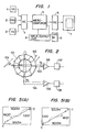
- the direction sensor 1 is constructed, as shown in Fig. 2, by an excitation coil 102 having an appropriate number of windings provided around the periphery of a toroidal core 101 , with two coils X103 and Y104 perpendicular to each other wound around the outside of the toroidal core 101, the coil: X103 and Y104 being connected to DC converters 107 and 108 through the intermediary of amplifiers 105 and 106 respectively, and with an alternating supply source connected to the excitation coil 102, and this direction sensor 1 is mounted in a vehicle with the coil X103 aligned in the east-west direction, and the coil Y104 in the north-south direction.
- the screen 700 of the display unit 7 consists of a dot matrix made up of liquid crystal display elements, as shown in Fig. 3, the vertical axis of the screen being the scanning direction, the scanning lines driven by a line driver 701, and the horizontal axis being the signal direction, the signal lines driven by a signal dirver 702.
- the line driver 701 and the signal driver 702 are connected to the microcomputer 5 as said above through the output interface 6.
- the operation of the direction sensor 1 of Fig. 2 detecting the direction of motion is as follows.
- a secondary voltage is induced in the coils X103 and Y104, that in X103 being the X component, and that in Y104 being the Y component.
- the output voltages V X and V Y of coil X and coil Y respectively become those given by the formulas (1) and (2):
- the direction of motion of the vehicle can be detected with respect to the direction of the earth's magnetism . Since the AC signals delivered from the coil X103 and the coil Y104 are weak, these signals are amplified by the amplifiers 105 and 106 respectively and converted into DC signals suitable for signal processing by the DC converters 107 and 108 so as to be input to the input interface circuit 4 .
- the driver inputs the position of his destination is, for instance X km east and Y O km north from the starting point, into the microcomputer 5 by means of the input-output unit 8.
- the outputs of the sensors are input to the microcomputer 5, the outputs of the direction sensor 1 and the tilt sensor 3 being first converted digitally in the input interface 4 .
- the horizontal component of the distance is calculated. That is, when the infinitesinal distance covered along the plane of motion is d 0 , the horizontal component of the distance covered is d H and the tilt angle is ⁇ for instance, the horizontal component of the distance covered d H is expressed by the following formula (4):
- the distance covered d H thus obtained is added continuously and, for each unit of the distance covered d being a little longer than d H , for instance, for each unit of 1m or 2m, the distance covered in the X direction and the Y direction are calculated according to the formulas (5) and (6) below . These distances are added sequentially, and the total distance covered X in the X direction and the total distance covered Y in the Y direction from the starting point are calculated .
- V Xk and Y Xk are the output signals from the direction sensor for the distance covered d.
- Y j are stored in the memory in pairs, as shown in Fig. 4, in cells with addresses prescribed so as to indicate the vehicle's movement from the starting point 0 (X 1 , Y 1 ) to its current position P (X i , Y.).
- the unit distances S 1 and S 2 in the X direction correspond to a so-called reduced scale, and when stored in the memory, they are stored at separate places A 1 and A 2 , respectively.
- the data on the vehicle's path stored in the memory is displayed on the display unit 7 according to the instructions of the microcomputer 5 .
- the microprocessor of the microcomputer 5 delivers a periodical signal to the line driver 701 shown in Fig. 3 and simultaneously, in synchronization therewith, specifies the address of X i in the memory, reads out the value of Y corresponding to X i and delivers this signal to the signal driver 702. Based on this signal, the vertical axis of the screen 700 of the display unit 7 is scanned by X i and the picture element corresponding to the signal Y j input along the horizontal axis is illuminated . In this way, the data on the vehicle is movement stored in the memory is displayed as a chart on the screen 700 of the display unit 7, and the position of the destination T is indicated on the screen simultaneously.
- the visibility of the picture element indicating the current position P is increased by being flashed .
- the data is changed to the data (X i , Y i ) memorized in A 1 through the calculation based on the above unit distance S 1 , and these are read out and displayed, whereby the vehicle's path is displayed on the screen at an enlarged scale.
- the display is altered so that the displayed position of the destination T is located above that of the starting point 0 on the screen by shifting the orientation of the screen as shown in Fig. 5 (B). That is, the scanning direction of the line driver 701 and the input signal sequence of the signal dirver 702 are reversed according to the instructions of the microprocessor.
- the current direction of motion is displayed on the screen 700 by an arrow 703 as shown in Fig. 3 or something similar.
- this embodiment of the present invention has the effect that the mutual positional relation drip between the current position and the destination can be understood intuitively, since the path of the vehicle from its starting point to the current position thereof, as well as its destination, is displayed on a chart.
- the device can be made to have a visibility which is excellent from the biotechnological viewpoint, since the position of the destination on the chart is displayed above that of the starting point at all times and since the direction of motion of the vehicle is indicated on the chart by an arrow .
- an alarm unit such as a buzzer or a chime
- an alarm unit such as a buzzer or a chime
- checkpoints could be provided and displayed as appropriate on the route from the starting point to the destination, and the travel could be done using each of these checkpoints as a guide, whereby the easy arrival at the destination can be made without losing the way .
- the present invention enables the driver to know intuitively the mutual positional relationship between the current position and the destination of the vehicle, and can make a device with excellent visibility
Abstract
Position display device includes a direction sensor (1) detecting the direction of motion of the vehicle, a distance sensor (2) detecting the distance travelled thereof and a tilt sensor (3) detecting the angle of tilt of the plane of motion. A microprocessor (5) calculates the changes in position of the vehicle on the basis of detection signals delivered from each of the sensors and delivers data on the movement of the vehicle. A display unit (7) display the position of the vehicle on it's screen.
Description
- The present invention relates to a position display device, and particularly to a position display device for a vehicle in motion such as an automobile which displays the movement of the vehicle on a screen .
- In recent years, a demand has risen for a device which provides the driver of a vehicle such as an automobile moving toward a destination with information on his driving which will serve as a guide for his driving, such as in what positional relationship said vehicle is in with its destination, and in what direction it should be driven so that it can reach the destination 9uickly and easily.
- One of such devices is a navigation meter mounted on an automobile the like, which provides displayed information on the current direction of motion of said vehicle and on the distance remaining to be covered for it to reach its destination, etc .
- However, this device wherein the positional relationship between the current position and the destination is simply displayed as the distance remaining is inconvenient in that the driver can not easily determine the best way of reaching his destination, since he does not known his position properly.
- The purpose of the present invention is to furnish a position display device for a vehicle in motion which enables the intvitive recognition of the mutual positional relationship between the current position and the destination of a vehicle in motion .
- The present invention is to enable the intuitive recognition of the mutual positional relationship between the current position and the destination and recognition of the course covered up to the current position by constructing a position display device for a vehicle in motion in such a manner that it is proviied with an input unit through which data on the position of the vehicle' s destination with respect to its starting point can be input, a direction sensor detecting the direction of motion of the vehicle, a distance sensor detecting the angle of tilt of the plane of motion, a microprocessor calculating the changes in position of the vehicle in terms of two or more different preset fixed intervals on the basis of detection signals delivered from each of the sensors and delivering data on the movement of the vehicle, a memory storing the data on the position of the destination and also the data on the movement of the vehicle sequentially in separate places, and with a display unit having a screen composed of picture elements arranged in the form of dot matrix reading out and displaying the contents of the memory concerning the destination selected by an instruction to the microprocessor on said screen in a sequence.
-
- Fig. 1 shows a block diagram of the complete configuration of one embodiment of the complete configuration of one embodiment of the present invention;
- Fig. 2 shows a diagram of the construction of a direction sensor used in the embodiment of Fig. 1 ;
- Fig. 3 shows a detailed diagram showing the configuration of the display unit of the embodiment of Fig. 1 ;
- Fig. 4 is a drawing showing how the data on the vehicle's path is stored in the memory ; and
- Figs . 5A and 5B are drawings illustrating the display .
- As shown in Fig. 1 , a direction sensor 1 detecting the direction of motion of a vehicle or the like, a
distance sensor 2 detecting the distance travelled by the vehicle and a tilt sensor 3 detecting the angle of tilt of the plane of motion are all connected to amicrocomputer 5 consisting of a microprocessor and a memory through the intermediary of aninput interface circuit 4. Themicrocomputer 5 is connected to a dot-matrix type ofdisplay unit 7 through the intermediary of anoutput interface circuit 6'. An input-output unit 8, including a keyboard, and anexternal memory 9 are connected to themicrocomputer 5 . Thisexternal memory 9 and the memory inside themicrocomputer 5 are such the contents of the memory can be read out from cells with specific addresses by the microprocessor. The direction sensor 1 is constructed, as shown in Fig. 2, by anexcitation coil 102 having an appropriate number of windings provided around the periphery of atoroidal core 101 , with two coils X103 and Y104 perpendicular to each other wound around the outside of thetoroidal core 101, the coil: X103 and Y104 being connected toDC converters amplifiers excitation coil 102, and this direction sensor 1 is mounted in a vehicle with the coil X103 aligned in the east-west direction, and the coil Y104 in the north-south direction. - The
screen 700 of thedisplay unit 7, consists of a dot matrix made up of liquid crystal display elements, as shown in Fig. 3, the vertical axis of the screen being the scanning direction, the scanning lines driven by aline driver 701, and the horizontal axis being the signal direction, the signal lines driven by asignal dirver 702. Theline driver 701 and thesignal driver 702 are connected to themicrocomputer 5 as said above through theoutput interface 6. - The operation of the embodiment thus constituted is described below
- The operation of the direction sensor 1 of Fig. 2 detecting the direction of motion is as follows. When an alternating voltage is applied to the
excitation coil 102, a secondary voltage is induced in the coils X103 and Y104, that in X103 being the X component, and that in Y104 being the Y component. Now suppose that a geomagnetism of H gauss, at an angle θ to the coils exists in the direction shown by thearrow 109 in Fig. 2, the output voltages VX and VY of coil X and coil Y respectively become those given by the formulas (1) and (2):

- According to these formulas, the angle θ is expressed by the following formula (3):

- Accordingly, by finding the angle according to the above formula (3), the direction of motion of the vehicle can be detected with respect to the direction of the earth's magnetism . Since the AC signals delivered from the coil X103 and the coil Y104 are weak, these signals are amplified by the
amplifiers DC converters input interface circuit 4 . - Now we return to Fig. 1 to explain the operation of the whole device.
- At the start of a journey, the driver inputs the position of his destination is, for instance X km east and YO km north from the starting point, into the
microcomputer 5 by means of the input-output unit 8. - While the vehicle is moving pulse signals in accordance with the distance covered are delivered from the
distance sensor 2, and analog signals in accordance with the angle of tilt ψ of the plane of motion are delivered from the tilt sensor 3 . The outputs of the sensors are input to themicrocomputer 5, the outputs of the direction sensor 1 and the tilt sensor 3 being first converted digitally in theinput interface 4 . - The following operations are conducted in the
microcomputer 5 . - First the pulses from the
distance sensor 2 are counted and thereby the distance covered is calculated . Next, based on this distance and the signal from the tilt sensor 3, the horizontal component of the distance is calculated. That is, when the infinitesinal distance covered along the plane of motion is d0, the horizontal component of the distance covered is dH and the tilt angle is ψ for instance, the horizontal component of the distance covered dH is expressed by the following formula (4):
- The distance covered dH thus obtained is added continuously and, for each unit of the distance covered d being a little longer than dH, for instance, for each unit of 1m or 2m, the distance covered in the X direction and the Y direction are calculated according to the formulas (5) and (6) below . These distances are added sequentially, and the total distance covered X in the X direction and the total distance covered Y in the Y direction from the starting point are calculated . In the formulas, VXk and YXk are the output signals from the direction sensor for the distance covered d.


- The values X calculated according to formula(s) are stored in the internal memory of the
microcomputer 5 or in theexternal memory 8 as sequential intervals X. (i = 1 ~ i) in two or more unit distances S1 and S2 in the X direction set beforehand, e.g. for S1 = 100 m and S2 = 1 km, while the values corresponding to the total distance covered Y in the Y direction at the same time, which are calculated according to formula (6), are also stored therein based on the interval Yj (j = 1 ~ j) in the Y direction using the same unit distances S and S2, where the interval Y. in the Y direction varies with respect to the interval X.. These values X. and Yj are stored in the memory in pairs, as shown in Fig. 4, in cells with addresses prescribed so as to indicate the vehicle's movement from the starting point 0 (X1, Y1) to its current position P (Xi, Y.). The unit distances S1 and S2 in the X direction correspond to a so-called reduced scale, and when stored in the memory, they are stored at separate places A1 and A2, respectively. - The data on the vehicle's path stored in the memory is displayed on the
display unit 7 according to the instructions of themicrocomputer 5 . The microprocessor of themicrocomputer 5 delivers a periodical signal to theline driver 701 shown in Fig. 3 and simultaneously, in synchronization therewith, specifies the address of Xi in the memory, reads out the value of Y corresponding to Xi and delivers this signal to thesignal driver 702. Based on this signal, the vertical axis of thescreen 700 of thedisplay unit 7 is scanned by Xi and the picture element corresponding to the signal Yj input along the horizontal axis is illuminated . In this way, the data on the vehicle is movement stored in the memory is displayed as a chart on thescreen 700 of thedisplay unit 7, and the position of the destination T is indicated on the screen simultaneously. - In addition, the visibility of the picture element indicating the current position P is increased by being flashed .
- When the distance to be travelled is small, that is, when there is only a short distance between the starting point and the destination or when the vehicle comes close to the destination, the data is changed to the data (Xi, Yi) memorized in A1 through the calculation based on the above unit distance S1, and these are read out and displayed, whereby the vehicle's path is displayed on the screen at an enlarged scale.
- If the points of the compass are fixed on the screen when the vehicle's movement is displayed, the direction of motion is towards the bottom of the screen when the vehicle travels from the
starting point 0 toward a destination T in the south, as shown in Fig. 5 (A), which could seem rather unnatural to the driver when driving. In this case, the display is altered so that the displayed position of the destination T is located above that of thestarting point 0 on the screen by shifting the orientation of the screen as shown in Fig. 5 (B). That is, the scanning direction of theline driver 701 and the input signal sequence of thesignal dirver 702 are reversed according to the instructions of the microprocessor. This means that the top of the screen is north when the destination input via the input-output unit is "YO km to the north" , and is south when the destination is "YO km to the south", and in accordance with this operation, the sequence of the read-out of the memory is controlled. - The current direction of motion is displayed on the
screen 700 by anarrow 703 as shown in Fig. 3 or something similar. - Accordingly, this embodiment of the present invention has the effect that the mutual positional relation drip between the current position and the destination can be understood intuitively, since the path of the vehicle from its starting point to the current position thereof, as well as its destination, is displayed on a chart.
- In addition, the device can be made to have a visibility which is excellent from the biotechnological viewpoint, since the position of the destination on the chart is displayed above that of the starting point at all times and since the direction of motion of the vehicle is indicated on the chart by an arrow .
- Moreover, since the positional relation ship between the vehicle's movement up to the current position displayed on the chart can be enlarged and thus the visibility is improved remarkably, the driver can devote himself to driving without referring to a road map or the like, which makes it easier for him to reach his destination.
- Furthermore, it is possible to provide an alarm unit, such as a buzzer or a chime, attached to the device and to make the alarm unit sound when the vehicle approaches the destination, and thereby make it possible to let the driver know that he is approaching his destination without him having to watch the screen of the display unit and thus attract his attention from the driving.
- With this embodiment, checkpoints could be provided and displayed as appropriate on the route from the starting point to the destination, and the travel could be done using each of these checkpoints as a guide, whereby the easy arrival at the destination can be made without losing the way .
- As explained above, the present invention enables the driver to know intuitively the mutual positional relationship between the current position and the destination of the vehicle, and can make a device with excellent visibility
Claims (4)
1. A position display device for a vehicle,
characterized by
characterized by
an input unit (8) through which data on the location of the vehicle's destination with respect to its starting point is supplied;
a direction sensor (1) detecting the direction of motion of said vehicle;
a distance sensor (2) detecting the distance travelled thereof;
a tilt sensor (3) detecting the angle of tilt of the plane of motion;
a microprocessor (5) calculating the changes in the position of said vehicle on the basis of detecting signals delivered from each of said sensors (1, 2, 3) and delivering data on the movement of said vehicle;
a memory (9) storing the location of said destination and said data on the vehicle's movement sequentially; and
a display unit (7) having a screen including picture elements arranged in the form of a matrix reading out and displaying the contents of said memory on said screen according to instructions from said microprocessor (5). [Fig. 1J
2. A position display device for a vehicle according to claim 1,
wherein said direction sensor is characterized by
a toroidal core (101), an excitation coil (102) wound on said toroidal core, two detecting coils (103, 104) wound on said toroidal core and perpendicular to each other, two D.C. converters (107, 108) connected to said detecting coils, two amplifiers (105, 106) connected to each converter, and an alternating current supply source connected to said excitation coil. [Fig. 2j
3. A position display device for a vehicle according to claim 1,
wherein said microprocessor calculates the changes in position of said vehicle in terms of at least two different preset fixed intervals on the basis of detection signals.
wherein said microprocessor calculates the changes in position of said vehicle in terms of at least two different preset fixed intervals on the basis of detection signals.
4. A position display device for a vehicle according to claim 1,
wherein said display unit (7) includes a dot matrix type liquid crystal display (700, 701, 702).
wherein said display unit (7) includes a dot matrix type liquid crystal display (700, 701, 702).
Applications Claiming Priority (2)
| Application Number | Priority Date | Filing Date | Title |
|---|---|---|---|
| JP19285581A JPS5895775A (en) | 1981-12-02 | 1981-12-02 | Display for position of running vehicle |
| JP192855/81 | 1981-12-02 |
Publications (1)
| Publication Number | Publication Date |
|---|---|
| EP0080736A1 true EP0080736A1 (en) | 1983-06-08 |
Family
ID=16298087
Family Applications (1)
| Application Number | Title | Priority Date | Filing Date |
|---|---|---|---|
| EP82111080A Withdrawn EP0080736A1 (en) | 1981-12-02 | 1982-12-01 | Position display device for a vehicle |
Country Status (2)
| Country | Link |
|---|---|
| EP (1) | EP0080736A1 (en) |
| JP (1) | JPS5895775A (en) |
Cited By (3)
| Publication number | Priority date | Publication date | Assignee | Title |
|---|---|---|---|---|
| FR2580839A1 (en) * | 1985-04-19 | 1986-10-24 | Honda Motor Co Ltd | DEVICE FOR DISPLAYING THE ROUTE TRAINED BY A VEHICLE |
| US4878170A (en) * | 1987-03-17 | 1989-10-31 | Zeevi Eliahu I | Vehicle navigation system |
| EP0487864A1 (en) * | 1990-11-28 | 1992-06-03 | Honda Giken Kogyo Kabushiki Kaisha | Apparatus for displaying a travel position |
Citations (5)
| Publication number | Priority date | Publication date | Assignee | Title |
|---|---|---|---|---|
| US4139889A (en) * | 1974-06-07 | 1979-02-13 | Ingels George W | Apparatus for vehicle position indication |
| GB2042181A (en) * | 1979-01-24 | 1980-09-17 | Nippon Telegraph & Telephone | Determining positional coordinates utilising the terrestrial magnetism as a directional reference |
| DE2910386A1 (en) * | 1979-03-16 | 1980-09-25 | Teldix Gmbh | Navigation system for road vehicles - has on-board computer to compare route information with monitored values from sensors |
| GB2056686A (en) * | 1979-08-10 | 1981-03-18 | Sperry Corp | Flux valve compass system |
| FR2470362A1 (en) * | 1979-11-24 | 1981-05-29 | Honda Motor Co Ltd | APPARATUS FOR INDICATING THE POSITION OF A VEHICLE |
-
1981
- 1981-12-02 JP JP19285581A patent/JPS5895775A/en active Pending
-
1982
- 1982-12-01 EP EP82111080A patent/EP0080736A1/en not_active Withdrawn
Patent Citations (5)
| Publication number | Priority date | Publication date | Assignee | Title |
|---|---|---|---|---|
| US4139889A (en) * | 1974-06-07 | 1979-02-13 | Ingels George W | Apparatus for vehicle position indication |
| GB2042181A (en) * | 1979-01-24 | 1980-09-17 | Nippon Telegraph & Telephone | Determining positional coordinates utilising the terrestrial magnetism as a directional reference |
| DE2910386A1 (en) * | 1979-03-16 | 1980-09-25 | Teldix Gmbh | Navigation system for road vehicles - has on-board computer to compare route information with monitored values from sensors |
| GB2056686A (en) * | 1979-08-10 | 1981-03-18 | Sperry Corp | Flux valve compass system |
| FR2470362A1 (en) * | 1979-11-24 | 1981-05-29 | Honda Motor Co Ltd | APPARATUS FOR INDICATING THE POSITION OF A VEHICLE |
Non-Patent Citations (1)
| Title |
|---|
| CONTROL ENGINEERING, vol. 9, no. 3, March 1962, pages 115,117, New York (USA); * |
Cited By (3)
| Publication number | Priority date | Publication date | Assignee | Title |
|---|---|---|---|---|
| FR2580839A1 (en) * | 1985-04-19 | 1986-10-24 | Honda Motor Co Ltd | DEVICE FOR DISPLAYING THE ROUTE TRAINED BY A VEHICLE |
| US4878170A (en) * | 1987-03-17 | 1989-10-31 | Zeevi Eliahu I | Vehicle navigation system |
| EP0487864A1 (en) * | 1990-11-28 | 1992-06-03 | Honda Giken Kogyo Kabushiki Kaisha | Apparatus for displaying a travel position |
Also Published As
| Publication number | Publication date |
|---|---|
| JPS5895775A (en) | 1983-06-07 |
Similar Documents
| Publication | Publication Date | Title |
|---|---|---|
| US5442557A (en) | Navigation device | |
| US4782447A (en) | System and method for navigating a vehicle | |
| US5268844A (en) | Electronic digital position and navigational plotter | |
| EP0572129A1 (en) | Navigation device | |
| EP0272078B1 (en) | Apparatus for display travel path | |
| EP0080736A1 (en) | Position display device for a vehicle | |
| EP0539146B1 (en) | Navigation system | |
| EP0355232A2 (en) | Road drawing system for a navigation apparatus | |
| JPH0315683B2 (en) | ||
| JPH04330484A (en) | Navigation device | |
| JP2003021527A (en) | Navigation device, display method and program | |
| JPH1047980A (en) | Navigation device for vehicle | |
| JP2000241175A5 (en) | A recording medium on which a map display device, a map display method, and a map display program are recorded. | |
| JPH06273184A (en) | Displaying method for route guiding apparatus of vehicle | |
| JP2000241175A (en) | Navigation device, method for processing navigation information, storage medium storing program for processing navigation program | |
| JP2639799B2 (en) | Driving information display device | |
| JPH0234890A (en) | Simple navigation device | |
| JPH0123046B2 (en) | ||
| JP2603781B2 (en) | Map data storage device and route guidance device | |
| JP2810278B2 (en) | Vehicle navigation system | |
| JP3278897B2 (en) | Navigation system for moving objects | |
| JP2973224B2 (en) | Automobile route guide device | |
| EP0731337A1 (en) | Navigation device | |
| JPH05232868A (en) | Navigation device | |
| JPH02141611A (en) | Route guide apparatus for vehicle |
Legal Events
| Date | Code | Title | Description |
|---|---|---|---|
| PUAI | Public reference made under article 153(3) epc to a published international application that has entered the european phase |
Free format text: ORIGINAL CODE: 0009012 |
|
| AK | Designated contracting states |
Designated state(s): DE FR GB |
|
| 17P | Request for examination filed |
Effective date: 19830609 |
|
| STAA | Information on the status of an ep patent application or granted ep patent |
Free format text: STATUS: THE APPLICATION IS DEEMED TO BE WITHDRAWN |
|
| 18D | Application deemed to be withdrawn |
Effective date: 19850702 |
|
| RIN1 | Information on inventor provided before grant (corrected) |
Inventor name: WATANABE, SHIGEHISA Inventor name: IGARASHI, ISAMU |