EP0081014A1 - Pressurised dispensing apparatus - Google Patents
Pressurised dispensing apparatus Download PDFInfo
- Publication number
- EP0081014A1 EP0081014A1 EP81305749A EP81305749A EP0081014A1 EP 0081014 A1 EP0081014 A1 EP 0081014A1 EP 81305749 A EP81305749 A EP 81305749A EP 81305749 A EP81305749 A EP 81305749A EP 0081014 A1 EP0081014 A1 EP 0081014A1
- Authority
- EP
- European Patent Office
- Prior art keywords
- piston
- product
- valve
- skirt
- axial ribs
- Prior art date
- Legal status (The legal status is an assumption and is not a legal conclusion. Google has not performed a legal analysis and makes no representation as to the accuracy of the status listed.)
- Withdrawn
Links
Images
Classifications
-
- B—PERFORMING OPERATIONS; TRANSPORTING
- B65—CONVEYING; PACKING; STORING; HANDLING THIN OR FILAMENTARY MATERIAL
- B65D—CONTAINERS FOR STORAGE OR TRANSPORT OF ARTICLES OR MATERIALS, e.g. BAGS, BARRELS, BOTTLES, BOXES, CANS, CARTONS, CRATES, DRUMS, JARS, TANKS, HOPPERS, FORWARDING CONTAINERS; ACCESSORIES, CLOSURES, OR FITTINGS THEREFOR; PACKAGING ELEMENTS; PACKAGES
- B65D83/00—Containers or packages with special means for dispensing contents
- B65D83/14—Containers or packages with special means for dispensing contents for delivery of liquid or semi-liquid contents by internal gaseous pressure, i.e. aerosol containers comprising propellant for a product delivered by a propellant
- B65D83/60—Contents and propellant separated
- B65D83/64—Contents and propellant separated by piston
Definitions
- This invention relates to pressurised dispensing apparatus.
- Aerosol or pressurised cans from which a product can be dispersed under pressure on opening a valve, are widely used.
- One known type'of dispenser is the piston can.
- the piston can is usually used when the product has a viscosity such that it is difficult to atomise. Examples of such products are caulking materials and shaving cream.
- a typical piston can comprises a cylindrical metal container capped with a valve, and contains a plastic cup or piston, dispensible material, and gas under pressure.
- the product rests on the piston, and the piston is supported by the gas.
- the valve When the valve is opened, the pressure exerted by the gas from the piston forces the piston and product towards, and the product through, the open valve.
- the effectiveness of a piston can is suitably measured by the amount of product which cannot be expelled from the can, i.e. the product remaining when opening of the valve no longer causes product expulsion. This point is reached when the piston comes as close as the design of can allows to the valve, or when most of the gas has escaped through the valve.
- the gas must not escape around the skirt of the piston (in addition to reducing delivery effectiveness, gas escape can. also contaminate the product).
- product must be prevented from adhering to the side walls of the can, as the piston is forced towards the valve.
- the product must be prevented from passing the piston, into the volume of the can occupied by the gas.
- a simple piston can is disclosed in US Patent Specification No. 3,132,570.
- the illustrated piston has a slightly flared skirt, with internal axial ribs.
- the flare allows product to accumulate between the piston and the can wall. Should the product not draw evenly from the can as the piston is propelled by the gas, the piston is liable to wobble. Wobbling increases the amount of product adhering to the wall. The result is a tendency for the piston to become skewed and/or lodged against the can wall, impeding product flow.
- US Patent Specification No. 3,255,936 discloses a flanged piston, for use in a piston can.
- US Patent Specification No. 3,381,863 discloses a piston having a generally frusto-conical shape.
- the base of the piston is formed as a seal with the wall of the can.
- the piston also includes a relatively flexible flange which "wipes " the wall as the piston travels towards the valve. Perhaps owing to the fact that such a piston has two circumferential flanges in contact with the can wall, the piston can be stably mounted in the can.
- US Patent Specification No. 4,023,717 discloses a piston whose generally right cylindrical skirt includes an intermediate section, around its circumference, which lightly contact the can wall or is expansible in the presence of loading pressure exerted by propellent gas.
- a similar product is disclosed in US Patent Specification No. 4,106,674; the piston illustrated there additionally comprises a circumferentially continuous tail structure having axially extending ribs, in order to reinforce the piston member.
- a piston of the type which can be used in pressurised cans comprises a top and a skirt, the skirt having at least three external axial ribs and, beneath the ribs, a circumferential rib or flange.
- a piston can according to the invention comprises a valve and contains a piston as defined. The can may also comprise a dispensible product above, and a pressurised gas beneath, the piston.
- a can for use in the invention can be of conventional design.
- it may comprise a generally cylindrical body, a valve, and a bottom with a resilient plug.
- the body can be seamed or seamless. It may be made of aluminium, metal or glass.
- the valve may be, for example, a nozzle valve or a foam valve. The presence of a plug in the bottom will depend on the filling process but its presence is usually preferred, in view of the preferred filling process.
- the preferred filling process is to introduce a product and the piston into the can.
- a valve is then crimped to the top of the can.
- a can bottom is already present or subsequently introduced, and the volume beneath the piston is pressurised by introducing gas into that volume through a hole in the can bottom which is then sealed by insertion of a resilient plug.
- the can is then ready for use, by actuation,of the valve, in order to open it.
- the pressurised gas forces the piston upwards.
- the piston reaches the top of the can.
- A.piston of the invention is preferably hollow.
- the configuration of its top is not critical, but is preferably shaped to conform to the shape of the interior of the top of the can. This ensures that the piston can move as far as possible towards the valve and thereby cause the expulsion of as much product as possible from the can.
- the piston further has a side wall or skirt whose exterior circumference generally corresponds to that of the interior of the can, i.e. it is usually right cylindrical.
- the circumferential rib or flange is preferably located at the foot of the skirt,i.e. along the bottom edge of the piston side wall. This flange provides a seal between the product and the pressurised gas, in use.
- the piston has, externally, axial ribs. There are preferably at least three evenly-spaced axial ribs. These ribs preferably extend from at or near the top of the piston side wall to the circumferential rib.
- the axial ribs define a space between the piston side wall and the can wall. Product can flow into this space and form a product seal.
- the ribs maintain the piston stably in the desired position coaxially with the can.
- the combined sealing effect of the product and the circumferential flange is effective, and the flange prevents excessive use of the product'as a sealant and also serves to "wipe" the can walls.
- the piston may be constructed of any suitable material, e.g. known plastics or light metals. The material used will be chosen having regard to the nature of the product to be dispensed and the pressurised gas. Suitable materials include terephthalates, ABS, acetals, acrylics, styrene-acrylonitrile, polyethylene, polypropylene and nylon.
- a piston can of the invention can dispense a large proportion of a dispensible product therefrom.
- the piston remains stable during dispensing, and only a minimal amount of the product is retained on the seal between the product and gas volumes of the can.
- the piston is suitable for use in seamed and seamless cans.
Abstract
@ A piston member (12) comprises a top (16) and a skirt (14), in which the skirt has at least three external axial ribs (20) and a circumferential rib or flange (18) beneath the axial ribs. The piston member can be mounted within a piston can (2) having a body (4), a valve (6), and a bottom (8) with a resilient plug (10). In use, with a pressurised gas beneath the piston and a dispensible product above the piston, dispensing the product by opening the valve proceeds smoothly, owing to the balancing effect provided by the axial ribs and the product seal between the skirt and the can wall.
Description
- This invention relates to pressurised dispensing apparatus.
- Aerosol or pressurised cans, from which a product can be dispersed under pressure on opening a valve, are widely used. One known type'of dispenser is the piston can. The piston can is usually used when the product has a viscosity such that it is difficult to atomise. Examples of such products are caulking materials and shaving cream.
- A typical piston can comprises a cylindrical metal container capped with a valve, and contains a plastic cup or piston, dispensible material, and gas under pressure. The product rests on the piston, and the piston is supported by the gas. When the valve is opened, the pressure exerted by the gas from the piston forces the piston and product towards, and the product through, the open valve.
- The effectiveness of a piston can is suitably measured by the amount of product which cannot be expelled from the can, i.e. the product remaining when opening of the valve no longer causes product expulsion. This point is reached when the piston comes as close as the design of can allows to the valve, or when most of the gas has escaped through the valve. In order to achieve a high degree of product delivery, three problems must be avoided. Firstly, the gas must not escape around the skirt of the piston (in addition to reducing delivery effectiveness, gas escape can. also contaminate the product). Secondly, product must be prevented from adhering to the side walls of the can, as the piston is forced towards the valve. Thirdly, the product must be prevented from passing the piston, into the volume of the can occupied by the gas.
- A simple piston can is disclosed in US Patent Specification No. 3,132,570. The illustrated piston has a slightly flared skirt, with internal axial ribs. The flare allows product to accumulate between the piston and the can wall. Should the product not draw evenly from the can as the piston is propelled by the gas, the piston is liable to wobble. Wobbling increases the amount of product adhering to the wall. The result is a tendency for the piston to become skewed and/or lodged against the can wall, impeding product flow.
- US Patent Specification No. 3,255,936 discloses a flanged piston, for use in a piston can. The space between the piston and the can wall, which separates the product from the gas, contains a sealing gel. The need to insert a sealing gel, in order to use such a piston can, is a disadvantage.
- US Patent Specification No. 3,915,353 discloses a piston having circumferential ribs. Such pistons require expensive tooling, including slides for opening of the mould. In order to make effective use of such a piston, a can containing it should have projections corresponding to the ribs.
- US Patent Specification No. 3,381,863 discloses a piston having a generally frusto-conical shape. The base of the piston is formed as a seal with the wall of the can. In order to reduce the degree to which product adheres to the can wall, the piston also includes a relatively flexible flange which "wipes " the wall as the piston travels towards the valve. Perhaps owing to the fact that such a piston has two circumferential flanges in contact with the can wall, the piston can be stably mounted in the can.
- US Patent Specification No. 4,023,717 discloses a piston whose generally right cylindrical skirt includes an intermediate section, around its circumference, which lightly contact the can wall or is expansible in the presence of loading pressure exerted by propellent gas.. A similar product is disclosed in US Patent Specification No. 4,106,674; the piston illustrated there additionally comprises a circumferentially continuous tail structure having axially extending ribs, in order to reinforce the piston member.
- According to the present invention, a piston of the type which can be used in pressurised cans comprises a top and a skirt, the skirt having at least three external axial ribs and, beneath the ribs, a circumferential rib or flange. A piston can according to the invention comprises a valve and contains a piston as defined. The can may also comprise a dispensible product above, and a pressurised gas beneath, the piston.
- A can for use in the invention can be of conventional design. For example, it may comprise a generally cylindrical body, a valve, and a bottom with a resilient plug. The body can be seamed or seamless. It may be made of aluminium, metal or glass. The valve may be, for example, a nozzle valve or a foam valve. The presence of a plug in the bottom will depend on the filling process but its presence is usually preferred, in view of the preferred filling process.
- The preferred filling process is to introduce a product and the piston into the can. A valve is then crimped to the top of the can. A can bottom is already present or subsequently introduced, and the volume beneath the piston is pressurised by introducing gas into that volume through a hole in the can bottom which is then sealed by insertion of a resilient plug. The can is then ready for use, by actuation,of the valve, in order to open it. As product is dispensed, the pressurised gas forces the piston upwards. When substantially all the product has been dispensed, the piston reaches the top of the can.
- A.piston of the invention is preferably hollow. The configuration of its top is not critical, but is preferably shaped to conform to the shape of the interior of the top of the can. This ensures that the piston can move as far as possible towards the valve and thereby cause the expulsion of as much product as possible from the can.
- The piston further has a side wall or skirt whose exterior circumference generally corresponds to that of the interior of the can, i.e. it is usually right cylindrical. The circumferential rib or flange is preferably located at the foot of the skirt,i.e. along the bottom edge of the piston side wall. This flange provides a seal between the product and the pressurised gas, in use.
- The piston has, externally, axial ribs. There are preferably at least three evenly-spaced axial ribs. These ribs preferably extend from at or near the top of the piston side wall to the circumferential rib.
- The axial ribs define a space between the piston side wall and the can wall. Product can flow into this space and form a product seal. The ribs maintain the piston stably in the desired position coaxially with the can. The combined sealing effect of the product and the circumferential flange is effective, and the flange prevents excessive use of the product'as a sealant and also serves to "wipe" the can walls. The piston may be constructed of any suitable material, e.g. known plastics or light metals. The material used will be chosen having regard to the nature of the product to be dispensed and the pressurised gas. Suitable materials include terephthalates, ABS, acetals, acrylics, styrene-acrylonitrile, polyethylene, polypropylene and nylon.
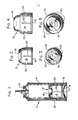
- The invention will now be illustrated, by way of example, with reference to the accompanying drawings, in which:
- Figure 1 is a sectional view of a piston can embodying the present invention;
- Figure 2 is a sectional view of one embodiment of a piston of the invention;
- Figure 3 is a top view of the piston of Figure 2;
- Figure 4 is a sectional view of an alternative piston embodying the present invention; and
- Figure 5 is a top view of the piston of Figure 4.
- Figure 1 shows a can 2 having a body 4, a valve a 6, a bottom 8 with a resilient plug 10, and/
piston 12. The piston is shown in greater detail in Figures 2 and 3; it is hollow, and has aside wall 14 and a top 16 having a shape corresponding to the inner top surface of the can 2. Theside wall 14 bears a circumferential flange orrib 18 and fouraxial ribs 20 extending along the length of the side wall. - Figures 4 and 5 illustrate an alternative piston, having the same components, illustrated by the same reference numerals, as are shown in Figures 2 and 3. The piston shown in Figures 4 and 5 has a domed top which includes a recess which mateswith the valve when the maximum amount of product has been dispensed.
- A piston can of the invention can dispense a large proportion of a dispensible product therefrom. The piston remains stable during dispensing, and only a minimal amount of the product is retained on the seal between the product and gas volumes of the can. The piston is suitable for use in seamed and seamless cans.
Claims (6)
1. A piston member comprising a top and a skirt, in which the skirt has at least three axial ribs and a circumferential rib or flange beneath the axial ribs.
2. A piston member according to claim 1, which has four axial ribs.
3. A piston member according to claim 1 or claim 2, in which the circumferential rib or flange defines the bottom of the skirt.
4. A piston member according to any preceding claim, in which the axial ribs contact, at their lower ends, the circumferential rib or flange.
5. A piston can containing a piston member according to any preceding claim.
6. A piston can according to claim 5, in which the top of the piston member is shaped to mate with the top of the can.
Priority Applications (1)
| Application Number | Priority Date | Filing Date | Title |
|---|---|---|---|
| EP81305749A EP0081014A1 (en) | 1981-12-04 | 1981-12-04 | Pressurised dispensing apparatus |
Applications Claiming Priority (1)
| Application Number | Priority Date | Filing Date | Title |
|---|---|---|---|
| EP81305749A EP0081014A1 (en) | 1981-12-04 | 1981-12-04 | Pressurised dispensing apparatus |
Publications (1)
| Publication Number | Publication Date |
|---|---|
| EP0081014A1 true EP0081014A1 (en) | 1983-06-15 |
Family
ID=8188472
Family Applications (1)
| Application Number | Title | Priority Date | Filing Date |
|---|---|---|---|
| EP81305749A Withdrawn EP0081014A1 (en) | 1981-12-04 | 1981-12-04 | Pressurised dispensing apparatus |
Country Status (1)
| Country | Link |
|---|---|
| EP (1) | EP0081014A1 (en) |
Cited By (3)
| Publication number | Priority date | Publication date | Assignee | Title |
|---|---|---|---|---|
| EP0523606A1 (en) * | 1991-07-17 | 1993-01-20 | United States Can Company | Floating piston for aerosol can |
| US5301664A (en) * | 1992-03-06 | 1994-04-12 | Sievers Robert E | Methods and apparatus for drug delivery using supercritical solutions |
| US5639441A (en) * | 1992-03-06 | 1997-06-17 | Board Of Regents Of University Of Colorado | Methods for fine particle formation |
Citations (8)
| Publication number | Priority date | Publication date | Assignee | Title |
|---|---|---|---|---|
| US3099370A (en) * | 1958-12-24 | 1963-07-30 | American Can Co | Dispensing container for viscous products |
| US3132570A (en) * | 1960-10-18 | 1964-05-12 | American Can Co | Piston construction for an aerosol container |
| US3255936A (en) * | 1964-01-03 | 1966-06-14 | Colgate Palmolive Co | Pressurized dispensing container |
| US3381863A (en) * | 1966-05-23 | 1968-05-07 | Edward J. Towns | Separating medium for use in pressurized dispensing containers |
| US3915352A (en) * | 1974-09-11 | 1975-10-28 | Christian T Scheindel | Aerosol can and piston assembly |
| US4023717A (en) * | 1974-04-09 | 1977-05-17 | Schultz Robert S | Pressure-operated container for viscous products |
| US4169547A (en) * | 1976-10-26 | 1979-10-02 | Glaxo Laboratories Limited | Ointment container with finger actuated piston |
| FR2432452A1 (en) * | 1978-08-01 | 1980-02-29 | Schultz Robert | Pressure-operated container for viscous products - has piston with circumferential continuous tail connected to and axially spaced from sealing band |
-
1981
- 1981-12-04 EP EP81305749A patent/EP0081014A1/en not_active Withdrawn
Patent Citations (8)
| Publication number | Priority date | Publication date | Assignee | Title |
|---|---|---|---|---|
| US3099370A (en) * | 1958-12-24 | 1963-07-30 | American Can Co | Dispensing container for viscous products |
| US3132570A (en) * | 1960-10-18 | 1964-05-12 | American Can Co | Piston construction for an aerosol container |
| US3255936A (en) * | 1964-01-03 | 1966-06-14 | Colgate Palmolive Co | Pressurized dispensing container |
| US3381863A (en) * | 1966-05-23 | 1968-05-07 | Edward J. Towns | Separating medium for use in pressurized dispensing containers |
| US4023717A (en) * | 1974-04-09 | 1977-05-17 | Schultz Robert S | Pressure-operated container for viscous products |
| US3915352A (en) * | 1974-09-11 | 1975-10-28 | Christian T Scheindel | Aerosol can and piston assembly |
| US4169547A (en) * | 1976-10-26 | 1979-10-02 | Glaxo Laboratories Limited | Ointment container with finger actuated piston |
| FR2432452A1 (en) * | 1978-08-01 | 1980-02-29 | Schultz Robert | Pressure-operated container for viscous products - has piston with circumferential continuous tail connected to and axially spaced from sealing band |
Cited By (4)
| Publication number | Priority date | Publication date | Assignee | Title |
|---|---|---|---|---|
| EP0523606A1 (en) * | 1991-07-17 | 1993-01-20 | United States Can Company | Floating piston for aerosol can |
| US5301664A (en) * | 1992-03-06 | 1994-04-12 | Sievers Robert E | Methods and apparatus for drug delivery using supercritical solutions |
| US5639441A (en) * | 1992-03-06 | 1997-06-17 | Board Of Regents Of University Of Colorado | Methods for fine particle formation |
| US6095134A (en) * | 1992-03-06 | 2000-08-01 | The Board Of Regents Of The University Of Co | Methods and apparatus for fine particle formation |
Similar Documents
| Publication | Publication Date | Title |
|---|---|---|
| EP0004100B1 (en) | A piston for ejecting a viscous or plastic mass | |
| JP2708725B2 (en) | Plastic container for flowable material and method of manufacturing the same | |
| US5292033A (en) | Dispenser for a liquid to pasty product and subplate for a dispenser of this kind | |
| US4269330A (en) | Cartridge type sauce extruder | |
| US3393842A (en) | Pressurized container with elastic inner container and method of assembling same | |
| US4169547A (en) | Ointment container with finger actuated piston | |
| US4776495A (en) | Disposable dispenser pump for products in liquid or paste form | |
| US4696415A (en) | Apparatus for dispensing products from a self-sealing dispenser | |
| US4134523A (en) | Vented piston for barrier pressure containers | |
| US4050612A (en) | Dispensing container | |
| US5509584A (en) | Head for dispensing a product, particularly a pasty product, and dispenser equipped with this head | |
| HU223435B1 (en) | Container with a sealed insert, and pump for opening said sealing | |
| EP0380348B1 (en) | Pressurizable dispensing container | |
| US4311255A (en) | Hand held container and dispenser assembly | |
| US5988453A (en) | Pressurized device | |
| EP0426408B1 (en) | Combined container and pump | |
| US5460207A (en) | Apparatus and method for filling and dispensing a highly viscous product from a container | |
| EP0503324A1 (en) | Dispenser for flowable materials | |
| US5484083A (en) | Receptacle with deformable flexible wall, of the bottle, pouch or tube type | |
| HU219054B (en) | Bottle for dividing liquid products and method for making same | |
| EP0081014A1 (en) | Pressurised dispensing apparatus | |
| EP1237812B1 (en) | Device for the controlled delivery of liquids or viscous or flowable substances | |
| US20020148854A1 (en) | Flexible tube dispenser for viscous materials with movable insert and method of assembly | |
| IE45367B1 (en) | Dispensing containers for viscous compositions | |
| JPH0217958A (en) | Closed apparatus for manual pump for distributing paste- or liquid-like product |
Legal Events
| Date | Code | Title | Description |
|---|---|---|---|
| PUAI | Public reference made under article 153(3) epc to a published international application that has entered the european phase |
Free format text: ORIGINAL CODE: 0009012 |
|
| AK | Designated contracting states |
Designated state(s): DE FR GB |
|
| 17P | Request for examination filed |
Effective date: 19831014 |
|
| STAA | Information on the status of an ep patent application or granted ep patent |
Free format text: STATUS: THE APPLICATION IS DEEMED TO BE WITHDRAWN |
|
| 18D | Application deemed to be withdrawn |
Effective date: 19850327 |
|
| RIN1 | Information on inventor provided before grant (corrected) |
Inventor name: FRENCH, FLOYD R. |