EP0082954A1 - Toroidal core electromagnetic device - Google Patents
Toroidal core electromagnetic device Download PDFInfo
- Publication number
- EP0082954A1 EP0082954A1 EP82110767A EP82110767A EP0082954A1 EP 0082954 A1 EP0082954 A1 EP 0082954A1 EP 82110767 A EP82110767 A EP 82110767A EP 82110767 A EP82110767 A EP 82110767A EP 0082954 A1 EP0082954 A1 EP 0082954A1
- Authority
- EP
- European Patent Office
- Prior art keywords
- core
- recited
- electromagnetic apparatus
- winding
- layers
- Prior art date
- Legal status (The legal status is an assumption and is not a legal conclusion. Google has not performed a legal analysis and makes no representation as to the accuracy of the status listed.)
- Ceased
Links
Images
Classifications
-
- H—ELECTRICITY
- H01—ELECTRIC ELEMENTS
- H01F—MAGNETS; INDUCTANCES; TRANSFORMERS; SELECTION OF MATERIALS FOR THEIR MAGNETIC PROPERTIES
- H01F27/00—Details of transformers or inductances, in general
- H01F27/28—Coils; Windings; Conductive connections
-
- H—ELECTRICITY
- H01—ELECTRIC ELEMENTS
- H01F—MAGNETS; INDUCTANCES; TRANSFORMERS; SELECTION OF MATERIALS FOR THEIR MAGNETIC PROPERTIES
- H01F27/00—Details of transformers or inductances, in general
- H01F27/24—Magnetic cores
- H01F27/25—Magnetic cores made from strips or ribbons
-
- H—ELECTRICITY
- H01—ELECTRIC ELEMENTS
- H01F—MAGNETS; INDUCTANCES; TRANSFORMERS; SELECTION OF MATERIALS FOR THEIR MAGNETIC PROPERTIES
- H01F30/00—Fixed transformers not covered by group H01F19/00
- H01F30/06—Fixed transformers not covered by group H01F19/00 characterised by the structure
- H01F30/16—Toroidal transformers
Definitions
- This invention relates to electromagnetic apparatus for use in electrical induction devices such as inductors, transformers, motors, generators and the like.
- the primary and secondary windings are formed into a common ring having a central opening or window.
- Two or more rings of magnetic core material are cut open, threaded through the winding window and closed, so that the rings of core material are distributed about the periphery of and encircle the windings.
- One of the problems with shell-type transformers is the difficulty of cutting and shaping the core material without degrading its magnetic properties.
- coretype transformers have been proposed wherein the core is formed into a ring, which is encircled by two or more groups of primary and secondary windings distributed around the periphery of the ring.
- Such core-type transformers are bulky and inefficient in terms of material utilization.
- transformers of the types described above heat developed by the windings and core during operation oftentimes results in a temperature rise of more than 50°C, increasing the deterioration rate of solid insulating materials in the core and windings as well as the liquid coolant in which the transformer is immersed. For these reasons, transformers of the type described generally result in higher purchase and maintenance costs and lower operating efficiencies than are considered desirable.
- the present invention provides an electromagnetic apparatus that is lighter, more compact, easier to build and far more efficient and reliable in operation than previous transformers of the shell or core type.
- the apparatus includes a magnetic core having an enclosed trunk defining a central opening, and a primary winding having at least three primary coil sections encircling the trunk and circumferentially spaced about the periphery of the core.
- the invention provides a method for making an electromagnetic apparatus comprising the steps of winding a plurality of layers of magnetically permeable material to form a magnetic core having an enclosed trunk defining a central opening; winding a plurality of layers of electrically conductive material on said core, the layers passing through the central opening and encircling the trunk to form thereon a primary coil section; and winding at least a second and a third primary coil section on the core, each primary coil section being formed of a plurality of layers of electrically conductive material passed through the central opening to encircle the trunk, and being circumferentially spaced about the periphery of the core.
- the invention provides an electromagnetic apparatus having a segmented secondary winding.
- the segmented secondary winding includes a plurality of cleft links that encircle the coil and the primary coil sections and are interconnected to provide a spiral current path.
- Each of the cleft links has a portion passing through the central opening of the coil and is circumferentially spaced about the periphery thereof.
- the apparatus of this invention has significant structural features. Less material is required by the toroidal core for a given power capacity. The magnetizing current is reduced, since the core has no air gap.
- a toroidal core is readily wound from strip material, and particularly adapted to utilize amorphous metal strip.
- the cleft links are readily manufactured or cast and press fit during assembly to form an outer shell that strengthens the apparatus and protects the core and windings within. Sectionialized arrangement of the primary and secondary coils improves heat dissipation, reducing temperature rise. As a result, the electromagnetic apparatus of the present invention has lower size, weight, and cost and higher operating efficiency and reliability than previous electromagnetic devices.
- Magnetic core 10 has a plurality of stacked toroids 12.
- Each of the toroids 12 are formed of coiled, magnetically permeable, strip material.
- seven stacked toroids 12. are employed, each having a height of approximately one inch and an inside diameter of 8.6 inches (21.84 cm) and an outside diameter of 14.3 inches (36.32 cm). It will be- appreciated, however, that the number of toroids stacked and their respective height and diameters can be altered, depending upon the required efficiency, volume, requirements to reduce eddy currents, power ratings, frequency, etc.
- Toroids 12 are separated from each other by annular insulators 14 which may be formed of any suitable insulating material such as thermosetting or thermoplastic material, glass cloth, fiberglass, polycarbonates, MICA, CAPSTAN, LEXAN, fish paper and the like, having the required flexibility, dielectric strength, toughness and stability at the designed operating temperature of the magnetic core, normally in the vicinity of 130°C.
- Insulating layers 14 are in the form of a flexible film having a thickness of about 1/2 mil (1.27 x 10" MM) and inside and outside diameters substantiaally matching that of the toroids 12. It will be appreciated that the insulating layers 14 need not be continuous but may be in the form of spaced elements, if desired.
- the insulating layers may, instead of being separate, be deposited by spraying, painting, etc.
- the core 10 can have a configuration other than toroidal, for example, an oval, rectangular, square or the like configuration, and a molded rather than wound construction.
- a similar insulating wrapping 16 is shown herein surrounding core 10 on all external sides, wrapping it in an insulating cocoon.
- the coiled strip material of toroids 12 is composed of magnetically soft material.
- Such material desirably has the following combination of properties:
- the amorphous magnetic alloys of core 10 are preferably formed by cooling a melt at a rate of about 10 5 to 10 °C/sec.
- a variety of well-known techniques are available for fabricating rapid-quenched continuous strip.
- the strip material of core 10 When used in magnetic cores for electromagnetic induction devices, the strip material of core 10 typically has the form of wire or ribbon. This strip material is conveniently prepared by casting molten material directly onto a chill surface or into a quenching medium of some sort. Such processing techniques considerably reduce the cost of fabrication, since no intermediate wire-drawing or ribbon-forming procedures are required.
- the amorphous metal alloys of which core 10 is preferably composed evidence high tensile strength, typically about 200,000 to 600,000 psi (1.38 x 10 6 - 4.14 x 10 6 k P a), depending on the particular composition. This is to be compared with polycrystalline alloys, which are used in the annealed condition and. which usually range from about 40,000 to 80,000 psi (2.76 x 10 6 - 5.52 x 10 6 kPa).
- a high tensile strength is an important consideration in applications where high centrifugal forces are present, such as experienced by cores in motors and generators, since higher strength alloys allow higher rotational speeds.
- the amorphous metal alloys used to form core 10 evidence a high electrical resistivity, ranging from about 160 to 180 microhm-cm (1.6 to 1.8 microhm meters) at 25°C, depending on the particular composition. Typical prior art materials have resistivities of about 45 to 160 microhm-cm (.45 to 1.60 microhm meters).
- the high resistivity possessed by the amorphous metal alloys defined above is useful in AC applications for minimizing eddy current losses, which in turn, are a factor in reducing core loss.
- a further advantage of using amorphous metal alloys to form core 10 is that lower coercive forces are obtained than with prior art compositions of substantially the same metallic content, thereby permitting more iron, which is relatively inexpensive, to be utilized in core 10, as compared with a greater proportion of nickel, which is more expensive.
- Each of the toroids 12 may be formed by windinq_successive turns onto a mandrel (not shown), keeping the strip material under tension to effect a tight formation.
- the number of turns is chosen depending upon the desired size of each toroid 12.
- the thickness of the strip material of toroids 12 is preferably in the range of 1 to 2 mils (2.54 x 10 -2 to 5 .0 8 x 10 -2 mm). D ue to the relatively high tensile strength of the amorphous alloy used herein, strip material having thickness of 1-2 mils (2.54 x 10- 2 to 5.08 x 10- 2 mm) can be used without fear of breakage. It will be appreciated that keeping the strip material relatively thin increases the effective resistivity since there are many boundaries per unit of radial length which eddy currents must pass through.
- a primary winding is shown herein as having at least 3 primary coil sections 18 encircling the trunk of core 10 and circumferentially spaced about the periphery thereof.
- the illustrated embodiment contains eighteen coils 18, formed of 84 turns of insulated strip aluminum approximately one inch wide (2.54 cm) and 0.005 inch (0.013 cm) thick. This arrangement provides a 6,000 volt primary, although other ratings are contemplated.
- the number of primary coil sections 18 employed can vary depending on the inside diameter of coil 10 the width and thickness of strip material used in the soil sections, the number of turns per section and the desired spacing between sections. Preferably, the number of primary coil sections ranges from about 10 to 30, and more preferably from about 16 to 20.
- coil 18 may vary dimensionally or may employ a round, square or other cross-section depending upon the voltage and power rating, available space, etc.
- Annular spacers 20 and 21, shown on either side of coils 18, may be formed of any suitable insulating material having mechanical and dielectric strength sufficient to withstand the transformer environment. Phenolic or materials described in connection with insulating layer 14 may be used in spacers 20 and 21. Each of the inside and outside diameters of annular spacers 20 and 21 is sufficient to completely overlay coils 18. Disposed adjacent to spacers 20 and 21 are eighteen ribs 23. As illustrated hereinafter, annular spacers 20 and 21 are identical and have a series of angularly spaced notches on the inside and outside perimeter for aligning secondary windings as described in more detail hereinafater. It will be understood that the electromagnetic apparatus of the invention can be used as an inductance, without a secondary windings or as a transformer or other electromagnetic device that utilizes secondary windings.
- the electromagnetic apparatus has a segmented secondary winding shown herein as a plurality of turns of inner conductors 22 and outer conductors 24.
- the conductors 22 and 24 are separated by annular spacers 26 and 27 on either side of conductors 22.
- Annular spacers 26 and 27 may be formed of an insulating material similar to that of spacers 20 and 21 and have an inside and outside diameter sized to fit the space within conductors 24.
- Conductors 22 and 24 form spiral or helical windings, one terminal of conductors 24 being shown as lead 28.
- FIG. 3 there is shown a perspective view of a portion of conductors 22 and 24. As illustrated, the conductors 22 and 24 are removed from their magnetic core and stretched apart to reveal internal details. Conductors 22 and 24 are made of aluminum and provide a spiral current path. This current path is formed from a cleft link shown herein as a U-shaped member comprising bottom piece 30, first leg 32 and second leg 34. Legs 32 and 34 are 1/2 inch (1.27 cm) in diameter and bottom piece 30 has a rectangular crosssection one inch (2.54 cm) high and 1/2 inch (1.27 cm) wide, although these shapes and the net cross-sectional areas can vary according to the current rating. The circuit of conductors 22 is effected by jumpers 36 which connect between legs 32 and 34.
- Legs 32 and 34 have both ends tapered and sized to force fit into tapered holes 37 at the ends of elements 30 and 36.
- each of the ends of legs 32, 34 and holes 37 have substantially the same angle of taper, whereby the contact area and contact pressure of the mating surfaces thereof are maximized.
- These joints can be splined or serrated to improve electrical conductivity and mechanical rigidity.
- Conductor 24 is formed of a cleft link comprising bottom piece 42, first leg 44 and second leg 46, each having the same cross-sectional dimensions as elements 30, 32, 34, respectively, but having different lengths. The lengths are chosen to allow a snug fit for conductors 22 around spacers 20 and 21 and for conductors 24 around spacers 26 and 27. In this embodiment, bottom pieces 30 and 42 will be aligned radially and are therefore shorter than their counterparts, jumpers 36 and 40, respectively.
- connection between conductors 22 and 24 is made by vertical rod 38, which is of length intermediate that of legs 34 and 46.
- the length brings the upper end of rod 38 even with legs 46 of conductors 24, allowing conductors 24 to fit around the beginning (not shown this view) of conductors 22 and form a nested structure.
- legs 46 can be sheathed by an insulating sleeve 48 to prevent shorting between adjacent turns of conductors 24.
- FIG. 4 depicts spacer 20 (and the underlying spacer 21 hidden from view), as having a plurality of evenly and angularly spaced notches, including inner notches 50 and outer notches 52.
- Second legs 34 lie along inner perimeter 54, while second legs 46 lie innermost along perimeter 56.
- the upper jumpers 36 and 40 shown in full, and the lower pieces 30 and 42, shown in phantom, effect the previously described connections.
- Fig. 5 shows, schematically, the inner or primary conductors 22 spiraling around core 10 and connecting to output terminals 60 and 61.
- the outer or secondary conductors 24 also spiral around core 10 and connect to terminals 62 and 63 and center tap 64.
- This spiraling of the secondary conductors 24 is depicted by the schematic of Fig. 4.
- the spiraling of conductors 22 is accomplished by leg 34a which descends and connects to outwardly extending piece 30a and thence to leg 32a and jumper 36a.
- Jumper 36a connects to the next succeeding link, that is, leg 34b.
- leg 34b This describes one complete turn which, in this fashion, proceeds and envelops the entire core.
- the spiraling of outer conductors 24 may be understood by considering inner leg 46a which connects to a bottom piece 42a and thence to outer leg 44a.
- Jumper 40a next connects across to a succeeding leg 46b. The foregoing describes one complete turn which can proceed to again envelope the core and windings 22.
- Inner legs 46 touch each other and inner legs 34. The latter fit into the junctures between adjacent ones of legs 46. However, legs 34 are spaced and legs 46 have insulating sleeves so there is no short circuiting of turns.
- the foregoing secondary has split windings 22 and 24, each having 26 turns, and each designed to produce 120 volts at 60 Hertz (240 volts total). Of course, other output voltages and frequencies are possible. It is contemplated that items 30, 32 and 34, as well as items 38, 42 and 44, will be pre-assembled; and items 30, 32 and 34 will be fitted into corresponding notches 50 and 52. Subsequently, jumpers 36 can be placed across the appropriate pair of legs 32 and 34 and individually or simultaneously pressed into place. Thereafter, elements 38, 42 and 44 can be fitted into or near notches 50 and 52, and jumpers 40 may be positioned across the appropriate legs 44 and 46 and then individually or simultaneously pressed into position.
- the segmented secondary can be comprised of a plurality of sections of wound ribbon connected in a series parallel manner.
- the number of sections ranges from 10 to 30, the number of turns of ribbon used in each section ranges from 10 to 100, the ribbon width ranges from .5 to 3 cm and the ribbon thickness ranges from .025 to 2 cm.
- the embodiment shown in Fig. 10 has 20 sections of 28 turns, each wound with 1/2" (1.27 cm) wide, .040" (0.1016 cm) thick ribbon. Twenty sections of the ribbon are connected in series parallel, as shown in Fig. 10. In the embodiment of Fig. 10, there are 10 sections in parallel for a cross-section area of .2" (0.508 cm).
- FIG. 6 the primary coils of the transformer of Fig. 1 are illustrated.
- an individual coil 18 is shown consisting of an split bobbin 70 onto which aluminum strip 72 is wound.
- Strip 72 has an insulating layer 74 which prevents shorting between adjacent turns. Connection to the coil 18 is made through inner end 76 and outer end 78 of strip 72.
- the bobbin is essentially a channel-like member following a rectangular track and having a center hole sized to fit about the core (core 10 of Fig. 1). In this embodiment, eighteen coils are used, each having eighty-four turns of strip material 72.
- each of the coils 18 will have a voltage drop of about 333 volts, a modest value.
- the potential difference between the beginning and ending coil is 6,000 volts and presents design limitations if adjacent. It is preferred, therefore, that the coils 18 be wired inconsecutively and grouped as illustrated in Fig. 7. As shown herein, coils 18 are grouped into four quadrants 80, 82, 84 and 86, positioned in that order, the coils in each quadrant being serially connected so they combine their voltages constructively.
- the coils 18 of quadrant 80 are connected between terminal 88 and lead 90.
- the coils of quadrant 86 connect between 90 and 92.
- the coils 18 of quadrant 84 connect between leads 92 and 94. Coils 18 of quadrant 82 are connected between leads 94 and terminal 96. All of the foregoing connections produce constructive combinations of the voltages of each quadrant. Significantly, the highest potential distance between the terminals of coils 18 exists between terminals 96 and 86, but these terminals are spaced by about 180 degrees. Accordingly, there is not an excessive electric field tending to cause a dielectric breakdown. Moreover, since the individual coils 18 have eighty-four turns over which 333 volts are dropped, the interlayer potential between each turn of coil 18 is only about four volts. This modest potential difference is easily accommodated by the insulating layer 74. In embodiments where coils 18 are composed of conventional layers of many turns of insulated wire, the potential difference between successive layers would be relatively higher.
- the electromagnetic apparatus described above is a power distribution transormer having a load loss of 240 watts at a 25 KVA capacity and weighing a total of 360 lbs. (163.3 kg) including case and oil.
- the transformer With an amorphous alloy core weighing 165 lbs. (74.8 kg) and operating at 13.5 kilogauss, the transformer has a core loss of only 16 watts.
- a distribution transformer of the same capacity and load loss using prior art cruciform design of the same amorphous alloy at the same flux density would weigh a total of 720 lbs. (326.5 kg). The core would weigh 260 lbs (117.9 kg) and would have a loss of 38 watts.
- Link 100 is a circular rod formed into a U-shaped member having right angle bends. Its tips 104 and 106 have inwardly directed teeth or serrations. Tips 104 and 106 are sized to fit holes 108 and 110, respectively, in jumper 102.
- Jumper 102 is a U-shaped bracket which may, in some embodiments, be formed of hollow tubes but is, in this embodiment, solid at its midsection. Jumpers 102 can replace jumpers 36 or 40 (with the appropriate dimensional adjustment) of Fig. 3.
- Link 100 can replace the links composed of elements 30, 32 and 34 and the links composed of elements 42, 44 and 46 (with the appropriate dimensional adjustments). It will be appreciated that in other embodiments, the connection between link 100 and jumper 102 can be effected with any approppriate fastener, including nuts and bolts.
- FIG. 9 a finished product is illustrated, the transformer of Fig. 1 being illustrated in phantom as assembly 112.
- assembly 112 since the assembly 112 has effectively a strong metal exoskeleton, (conductors 22 and 24 of Fig. 1), it is therefore highly resistant to shock. Assembly 112 may rest on any appropriate platform or on struts, which leave the bottom of assembly 112 open for cooling purposes. Assembly 112 is shown mounted within shell 114 which may be filled with a cooling medium, such as oil. Since transformer 112 is a relatively open structure exposing much of core 10, cooling is greatly facilitated. In particular, there are significant spaces between coils 18 (Fig. I), so that oil-can pass through conductors 22 and 24 and intimately contact core 10.
- a high voltage primary connection is made through terminals 118 and 120 mounted atop high voltage insulating standoffs 122 and 124, respectively.
- Standoffs 122 and 124 are mounted on cover 128 and provide through internal conductors (not shown) continuity to transformer 112.
- Cover 128 seals shell 114 and prevents leakage of its oil.
- Secondary connections are shown herein as output terminals 130 and 132 and 134, which correspond to terminals 62, 64 and 60 of Fig. 5. It will be noted that the overall height of the assembly of Fig. 9 is relatively small due to the toroidal construction of the transformer. Lightning arrestors 136 and 138 can bypass dangerous over-voltages from terminals 118 and 120 to the shell 114, which is grounded.
- the current and voltage rating may be altered by changing the size and the number of turns of the conductors in the windings.
- a variety of containers may be used to house the transformer.
- the sequence for connecting primary windings may be changed, especially for low voltage applications. While oil coolants are mentioned in some embodiments, different liquid and gaseous coolants may be substituted.
- the primary is shown enveloped by the secondary; but this arrangement of the windings may be reversed in other embodiments. Moreover, the function of primary and secondary may be reversed.
- the various fixtures shown for supporting and insulating the windings may be reshaped and made of alternate materials depending upon the desired dielectric strength, weight and structural integrity thereof. Although aluminum conductors are described herein, alternate conducting materials may be employed depending upon the weight, resistivity and other requirements.
Abstract
An electromagnetic apparatus is provided with a magnetic core and a segmented electrical winding. The core has an enclosed trunk defining a central opening. At least three coil sections of the electrical winding encircle the trunk and are circumferentially spaced about the periphery of the core.
Description
- This invention relates to electromagnetic apparatus for use in electrical induction devices such as inductors, transformers, motors, generators and the like.
- In the manufacture of shell-type transformers, the primary and secondary windings are formed into a common ring having a central opening or window. Two or more rings of magnetic core material are cut open, threaded through the winding window and closed, so that the rings of core material are distributed about the periphery of and encircle the windings. One of the problems with shell-type transformers is the difficulty of cutting and shaping the core material without degrading its magnetic properties. To overcome this problem, coretype transformers have been proposed wherein the core is formed into a ring, which is encircled by two or more groups of primary and secondary windings distributed around the periphery of the ring. Such core-type transformers are bulky and inefficient in terms of material utilization. Moreover, in transformers of the types described above, heat developed by the windings and core during operation oftentimes results in a temperature rise of more than 50°C, increasing the deterioration rate of solid insulating materials in the core and windings as well as the liquid coolant in which the transformer is immersed. For these reasons, transformers of the type described generally result in higher purchase and maintenance costs and lower operating efficiencies than are considered desirable.
- The present invention provides an electromagnetic apparatus that is lighter, more compact, easier to build and far more efficient and reliable in operation than previous transformers of the shell or core type. Generally stated, the apparatus includes a magnetic core having an enclosed trunk defining a central opening, and a primary winding having at least three primary coil sections encircling the trunk and circumferentially spaced about the periphery of the core.
- In addition, the invention provides a method for making an electromagnetic apparatus comprising the steps of winding a plurality of layers of magnetically permeable material to form a magnetic core having an enclosed trunk defining a central opening; winding a plurality of layers of electrically conductive material on said core, the layers passing through the central opening and encircling the trunk to form thereon a primary coil section; and winding at least a second and a third primary coil section on the core, each primary coil section being formed of a plurality of layers of electrically conductive material passed through the central opening to encircle the trunk, and being circumferentially spaced about the periphery of the core.
- Further, the invention provides an electromagnetic apparatus having a segmented secondary winding. The segmented secondary winding includes a plurality of cleft links that encircle the coil and the primary coil sections and are interconnected to provide a spiral current path. Each of the cleft links has a portion passing through the central opening of the coil and is circumferentially spaced about the periphery thereof.
- . The apparatus of this invention has significant structural features. Less material is required by the toroidal core for a given power capacity. The magnetizing current is reduced, since the core has no air gap. A toroidal core is readily wound from strip material, and particularly adapted to utilize amorphous metal strip. The cleft links are readily manufactured or cast and press fit during assembly to form an outer shell that strengthens the apparatus and protects the core and windings within. Sectionialized arrangement of the primary and secondary coils improves heat dissipation, reducing temperature rise. As a result, the electromagnetic apparatus of the present invention has lower size, weight, and cost and higher operating efficiency and reliability than previous electromagnetic devices.
- The invention will be more fully understood and further advantages will become apparent when reference is made to the following detailed description of the preferred embodiments of the invention and the accompanying drawings, in which:
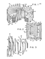
- Fig. 1 is an isometric view of an electromagnetic device, portions broken away for illustrative purposes, according to the teachings of the present invention;
- Fig. 2 is a cross-sectional view taken through the trunk of the electromagnetic device of Fig. 1;
- Fig. 3 is a perspective view of windings removed from the electromagnetic device of Fig. 1 and stretched apart for illustrative purposes;
- Fig. 4 is a partial schematic illustration of the secondary winding of the electromagnetic device of Fig. 1;
- Fig. 5 is a schematic illustration of the secondary winding of the electromagnetic device of Fig. 1;
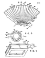
- Fig. 6 is a perspective view of one of the primary coils of the electromagnetic device of Fig. 1;
- Fig. 7 is a schematic illustration of the interconnection of primary coils of the electromagnetic device of Fig. 1;
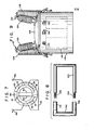
- Fig. 8 is a side view of another cleft link and jumper which is an alternate to those shown in Fig. 3;
- Fig. 9 is a front view of the finished transformer; and
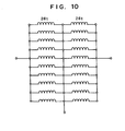
- Fig. 10 is a schemtic electrical diagram of a segmented secondary having a plurality of sections each of which is comprised of a plurality of layers of strip material.
- Referring to Figs. 1 and 2, there is illustrated an electromagnetic apparatus adapted to operate as a transformer having a 25 KVA rating although, obviously, other ratings are contemplated.
Magnetic core 10 has a plurality of stackedtoroids 12. Each of thetoroids 12 are formed of coiled, magnetically permeable, strip material. In the embodiment shown, seven stacked toroids 12.are employed, each having a height of approximately one inch and an inside diameter of 8.6 inches (21.84 cm) and an outside diameter of 14.3 inches (36.32 cm). It will be- appreciated, however, that the number of toroids stacked and their respective height and diameters can be altered, depending upon the required efficiency, volume, requirements to reduce eddy currents, power ratings, frequency, etc.Toroids 12 are separated from each other byannular insulators 14 which may be formed of any suitable insulating material such as thermosetting or thermoplastic material, glass cloth, fiberglass, polycarbonates, MICA, CAPSTAN, LEXAN, fish paper and the like, having the required flexibility, dielectric strength, toughness and stability at the designed operating temperature of the magnetic core, normally in the vicinity of 130°C. Insulating layers 14 are in the form of a flexible film having a thickness of about 1/2 mil (1.27 x 10" MM) and inside and outside diameters substantiaally matching that of thetoroids 12. It will be appreciated that theinsulating layers 14 need not be continuous but may be in the form of spaced elements, if desired. Also, the insulating layers may, instead of being separate, be deposited by spraying, painting, etc. Moreover, thecore 10 can have a configuration other than toroidal, for example, an oval, rectangular, square or the like configuration, and a molded rather than wound construction. A similarinsulating wrapping 16 is shown herein surroundingcore 10 on all external sides, wrapping it in an insulating cocoon. - The coiled strip material of
toroids 12 is composed of magnetically soft material. Such material desirably has the following combination of properties: - (a) low hysteresis loss; (b) low eddy current loss;
- (c) low coercive force; (d) high magnetic permeability;
- (e) high saturation value; and (f) minimum change in permeability with temperature. Conventionally employed magnetically soft material in strip form, such as high- purity iron, silicon steels, iron/nickel alloys, iron/ cobalt alloys and the like, are all suitable for use in the practice of the present invention. Particularly suitable, however, is strip material of amorphous (glassy) magnetic alloys which have recently become available. Such alloys are at least about 50% amorphous, as determined by x-ray diffraction. Such alloys include those having the formula (M60-90 T0-15 X10-25), wherein M is at least one of the elements iron, cobalt and nickel, T is at least one of the transition metal elements, and X is at least one of the metalloid elements of phosphorus, boron and carbon. Up to 80 percent of the carbon, phosphorus and/ or boron in X may be replaced by aluminum, antimony, beryllium, germanium, indium, silicon and tin. Used as cores of magnetic devices, such amorphous metal alloys evidence generally superior properties as compared to the conventional polycrystalline metal alloys commonly utilized. Preferably, strips of such amorphous alloys are at least about 80% amorphous, more preferably yet, at least about 95% amorphous.
- The amorphous magnetic alloys of
core 10 are preferably formed by cooling a melt at a rate of about 105 to 10 °C/sec. A variety of well-known techniques are available for fabricating rapid-quenched continuous strip. When used in magnetic cores for electromagnetic induction devices, the strip material ofcore 10 typically has the form of wire or ribbon. This strip material is conveniently prepared by casting molten material directly onto a chill surface or into a quenching medium of some sort. Such processing techniques considerably reduce the cost of fabrication, since no intermediate wire-drawing or ribbon-forming procedures are required. - The amorphous metal alloys of which
core 10 is preferably composed evidence high tensile strength, typically about 200,000 to 600,000 psi (1.38 x 10⁶ - 4.14 x 10⁶ kPa), depending on the particular composition. This is to be compared with polycrystalline alloys, which are used in the annealed condition and. which usually range from about 40,000 to 80,000 psi (2.76 x 10⁶ - 5.52 x 10⁶ kPa). A high tensile strength is an important consideration in applications where high centrifugal forces are present, such as experienced by cores in motors and generators, since higher strength alloys allow higher rotational speeds. - In addition, the amorphous metal alloys used to form
core 10 evidence a high electrical resistivity, ranging from about 160 to 180 microhm-cm (1.6 to 1.8 microhm meters) at 25°C, depending on the particular composition. Typical prior art materials have resistivities of about 45 to 160 microhm-cm (.45 to 1.60 microhm meters). The high resistivity possessed by the amorphous metal alloys defined above is useful in AC applications for minimizing eddy current losses, which in turn, are a factor in reducing core loss. - A further advantage of using amorphous metal alloys to form
core 10 is that lower coercive forces are obtained than with prior art compositions of substantially the same metallic content, thereby permitting more iron, which is relatively inexpensive, to be utilized incore 10, as compared with a greater proportion of nickel, which is more expensive. - Each of the
toroids 12 may be formed by windinq_successive turns onto a mandrel (not shown), keeping the strip material under tension to effect a tight formation. The number of turns is chosen depending upon the desired size of eachtoroid 12. The thickness of the strip material oftoroids 12 is preferably in the range of 1 to 2 mils (2.54 x 10⁻² to 5.08 x 10⁻²mm). Due to the relatively high tensile strength of the amorphous alloy used herein, strip material having thickness of 1-2 mils (2.54 x 10⁻² to 5.08 x 10⁻²mm) can be used without fear of breakage. It will be appreciated that keeping the strip material relatively thin increases the effective resistivity since there are many boundaries per unit of radial length which eddy currents must pass through. - A primary winding is shown herein as having at least 3
primary coil sections 18 encircling the trunk ofcore 10 and circumferentially spaced about the periphery thereof. The illustrated embodiment contains eighteencoils 18, formed of 84 turns of insulated strip aluminum approximately one inch wide (2.54 cm) and 0.005 inch (0.013 cm) thick. This arrangement provides a 6,000 volt primary, although other ratings are contemplated. The number ofprimary coil sections 18 employed can vary depending on the inside diameter ofcoil 10 the width and thickness of strip material used in the soil sections, the number of turns per section and the desired spacing between sections. Preferably, the number of primary coil sections ranges from about 10 to 30, and more preferably from about 16 to 20. Moreover,coil 18 may vary dimensionally or may employ a round, square or other cross-section depending upon the voltage and power rating, available space, etc. -
Annular spacers coils 18, may be formed of any suitable insulating material having mechanical and dielectric strength sufficient to withstand the transformer environment. Phenolic or materials described in connection with insulatinglayer 14 may be used inspacers annular spacers ribs 23. As illustrated hereinafter,annular spacers - In accordance with the present invention, the electromagnetic apparatus has a segmented secondary winding shown herein as a plurality of turns of
inner conductors 22 andouter conductors 24. Theconductors annular spacers conductors 22.Annular spacers spacers conductors 24.Conductors conductors 24 being shown aslead 28. - Referring to Fig. 3, there is shown a perspective view of a portion of
conductors conductors Conductors bottom piece 30,first leg 32 andsecond leg 34.Legs bottom piece 30 has a rectangular crosssection one inch (2.54 cm) high and 1/2 inch (1.27 cm) wide, although these shapes and the net cross-sectional areas can vary according to the current rating. The circuit ofconductors 22 is effected byjumpers 36 which connect betweenlegs Legs holes 37 at the ends ofelements legs -
Conductor 24 is formed of a cleft link comprisingbottom piece 42,first leg 44 andsecond leg 46, each having the same cross-sectional dimensions aselements conductors 22 aroundspacers conductors 24 aroundspacers bottom pieces jumpers - It will be observed that the connection between
conductors vertical rod 38, which is of length intermediate that oflegs rod 38 even withlegs 46 ofconductors 24, allowingconductors 24 to fit around the beginning (not shown this view) ofconductors 22 and form a nested structure. It will be noted thatlegs 46 can be sheathed by an insulatingsleeve 48 to prevent shorting between adjacent turns ofconductors 24. - In Figs. 4 and 5, there is illustrated schematically, the secondary winding of Fig. 3. Fig. 4 depicts spacer 20 (and the
underlying spacer 21 hidden from view), as having a plurality of evenly and angularly spaced notches, includinginner notches 50 andouter notches 52.Second legs 34 lie alonginner perimeter 54, whilesecond legs 46 lie innermost alongperimeter 56. Theupper jumpers lower pieces primary conductors 22 spiraling aroundcore 10 and connecting to output terminals 60 and 61. The outer orsecondary conductors 24 also spiral aroundcore 10 and connect to terminals 62 and 63 andcenter tap 64. - This spiraling of the
secondary conductors 24 is depicted by the schematic of Fig. 4. For example, the spiraling ofconductors 22 is accomplished by leg 34a which descends and connects to outwardly extending piece 30a and thence to leg 32a and jumper 36a. Jumper 36a connects to the next succeeding link, that is,leg 34b. This describes one complete turn which, in this fashion, proceeds and envelops the entire core. The spiraling ofouter conductors 24 may be understood by considering inner leg 46a which connects to a bottom piece 42a and thence to outer leg 44a. Jumper 40a next connects across to a succeedingleg 46b. The foregoing describes one complete turn which can proceed to again envelope the core and windings 22. -
Inner legs 46 touch each other andinner legs 34. The latter fit into the junctures between adjacent ones oflegs 46. However,legs 34 are spaced andlegs 46 have insulating sleeves so there is no short circuiting of turns. - The foregoing secondary has split
windings items items items corresponding notches jumpers 36 can be placed across the appropriate pair oflegs elements notches jumpers 40 may be positioned across theappropriate legs - Alternatively, as shown in Fig. 10, the segmented secondary can be comprised of a plurality of sections of wound ribbon connected in a series parallel manner. In general, the number of sections ranges from 10 to 30, the number of turns of ribbon used in each section ranges from 10 to 100, the ribbon width ranges from .5 to 3 cm and the ribbon thickness ranges from .025 to 2 cm. The embodiment shown in Fig. 10 has 20 sections of 28 turns, each wound with 1/2" (1.27 cm) wide, .040" (0.1016 cm) thick ribbon. Twenty sections of the ribbon are connected in series parallel, as shown in Fig. 10. In the embodiment of Fig. 10, there are 10 sections in parallel for a cross-section area of .2" (0.508 cm).
- Referring to Figs. 6 and 7, the primary coils of the transformer of Fig. 1 are illustrated. In Fig. 6, an
individual coil 18 is shown consisting of ansplit bobbin 70 onto whichaluminum strip 72 is wound. Use ofbobbin 70 is optional, sinceindividual coil 18 can be self supporting.Strip 72 has an insulatinglayer 74 which prevents shorting between adjacent turns. Connection to thecoil 18 is made throughinner end 76 andouter end 78 ofstrip 72. The bobbin is essentially a channel-like member following a rectangular track and having a center hole sized to fit about the core (core 10 of Fig. 1). In this embodiment, eighteen coils are used, each having eighty-four turns ofstrip material 72. Accordingly, for a 6,000 volt primary, each of thecoils 18 will have a voltage drop of about 333 volts, a modest value. However, the potential difference between the beginning and ending coil is 6,000 volts and presents design limitations if adjacent. It is preferred, therefore, that thecoils 18 be wired inconsecutively and grouped as illustrated in Fig. 7. As shown herein, coils 18 are grouped into fourquadrants coils 18 ofquadrant 80 are connected betweenterminal 88 and lead 90. The coils ofquadrant 86 connect between 90 and 92. Thecoils 18 ofquadrant 84 connect betweenleads Coils 18 ofquadrant 82 are connected between leads 94 andterminal 96. All of the foregoing connections produce constructive combinations of the voltages of each quadrant. Significantly, the highest potential distance between the terminals ofcoils 18 exists betweenterminals individual coils 18 have eighty-four turns over which 333 volts are dropped, the interlayer potential between each turn ofcoil 18 is only about four volts. This modest potential difference is easily accommodated by the insulatinglayer 74. In embodiments where coils 18 are composed of conventional layers of many turns of insulated wire, the potential difference between successive layers would be relatively higher. - The electromagnetic apparatus described above is a power distribution transormer having a load loss of 240 watts at a 25 KVA capacity and weighing a total of 360 lbs. (163.3 kg) including case and oil. With an amorphous alloy core weighing 165 lbs. (74.8 kg) and operating at 13.5 kilogauss, the transformer has a core loss of only 16 watts. A distribution transformer of the same capacity and load loss using prior art cruciform design of the same amorphous alloy at the same flux density would weigh a total of 720 lbs. (326.5 kg). The core would weigh 260 lbs (117.9 kg) and would have a loss of 38 watts. Conventional 25 KVA transformers in current use have silicon-iron cores operating at 16 to 17 kilogauss and have load losses of 300 to 500 watts and core losses of 90 to 113 watts. With power companies willing to pay a bonus for lower core losses, and to a lesser extent for lower load losses, the most recent 25 KVA design using the best grain oriented silicon-iron core weighs 400 lbs (181.44 kg) and has core loss of 87 watts and a load loss of 250 watts. It is evident from the foregoing that a transformer constructed in accordance with the present invention would have the highest loss bonus and the lowest material contents.
- Referring to Fig. 8, an alternate link and jumper is shown as
link 100 andjumper 102.Link 100 is a circular rod formed into a U-shaped member having right angle bends. Itstips Tips holes jumper 102.Jumper 102 is a U-shaped bracket which may, in some embodiments, be formed of hollow tubes but is, in this embodiment, solid at its midsection.Jumpers 102 can replacejumpers 36 or 40 (with the appropriate dimensional adjustment) of Fig. 3.Link 100 can replace the links composed ofelements elements link 100 andjumper 102 can be effected with any approppriate fastener, including nuts and bolts. - Referring to Fig. 9, a finished product is illustrated, the transformer of Fig. 1 being illustrated in phantom as
assembly 112. It will be appreciated that since theassembly 112 has effectively a strong metal exoskeleton, (conductors Assembly 112 may rest on any appropriate platform or on struts, which leave the bottom ofassembly 112 open for cooling purposes.Assembly 112 is shown mounted withinshell 114 which may be filled with a cooling medium, such as oil. Sincetransformer 112 is a relatively open structure exposing much ofcore 10, cooling is greatly facilitated. In particular, there are significant spaces between coils 18 (Fig. I), so that oil-can pass throughconductors core 10. A high voltage primary connection is made throughterminals 118 and 120 mounted atop highvoltage insulating standoffs Standoffs cover 128 and provide through internal conductors (not shown) continuity totransformer 112. Cover 128 seals shell 114 and prevents leakage of its oil. Secondary connections are shown herein asoutput terminals terminals 62, 64 and 60 of Fig. 5. It will be noted that the overall height of the assembly of Fig. 9 is relatively small due to the toroidal construction of the transformer.Lightning arrestors terminals 118 and 120 to theshell 114, which is grounded. - It is to be appreciated that various modifications may be implemented with respect to the above-described preferred embodiments. The current and voltage rating may be altered by changing the size and the number of turns of the conductors in the windings. A variety of containers may be used to house the transformer. The sequence for connecting primary windings may be changed, especially for low voltage applications. While oil coolants are mentioned in some embodiments, different liquid and gaseous coolants may be substituted. The primary is shown enveloped by the secondary; but this arrangement of the windings may be reversed in other embodiments. Moreover, the function of primary and secondary may be reversed. The various fixtures shown for supporting and insulating the windings may be reshaped and made of alternate materials depending upon the desired dielectric strength, weight and structural integrity thereof. Although aluminum conductors are described herein, alternate conducting materials may be employed depending upon the weight, resistivity and other requirements.
- Having thus described the invention in rather full detail, it will be understood that these details need not be strictly adhered to but that various changes or modifications may suggest themselves to one skilled in the art, all falling within the scope of the invention as defined by the subjoined claims.
Claims (10)
1. An electromagnetic apparatus comprising:
(a) a magnetic core having an enclosed trunk defining a central opening; and
(b) a primary winding having at least three primary coil sections encircling said trunk and circumferentially spaced about the periphery of said core.
2. An electromagnetic apparatus as recited in claim 1, wherein said core has a toroidal configuration.
3. An electromagnetic apparatus as recited in claim 2, wherein the number of said primary coil sections ranges from 10 to 30.
4. An electromagnetic apparatus as recited in claim 2, wherein said magnetic core has a plurality of layers of insulated magnetically permeable strip material.
5. An electromagnetic device according to claim 1, wherein said magnetically permeable strip material is composed of a metal alloy that is at least 50 percent amorphous and has a composition defined by the formula M60-90 TO-15 X10-25, wherein M is at least one of the elements iron, cobalt and nickel, T is at least one of the transition metal elements and X is at least one of the metalloid elements phosphorus, boron and carbon.
6. An electromagnetic apparatus as recited in claim 1, and further comprising a segmented secondary winding.
7. An electromagnetic apparatus as recited in claim 6, wherein said core comprises:
a plurality of stacked toroids of coiled, uninsulated, magnetically permeable, strip material.
8. An electromagnetic apparatus as recited in claim 6, further comprising:
an annular spacer positioned atop said core and having a plurality of angularly spaced notches, said segmented winding being fitted into said notches.
9. A method for building an electromagnetic apparatus comprising the steps of:
(a) winding a plurality of layers of magnetically permeable strip material to form a magnetic core having an enclosed trunk defining a central opening;
(b) winding a plurality of layers of electrically conductive material on said core, said layers passing through said central opening and encircling said trunk to form thereon a primary coil section; and
(c) winding at least a second and a third primary coil section on said core, each primary coil section being formed of a plurality of layers of electrically conductive material passed through said central opening to encircle said trunk, and being circumferentially spaced about the periphery of said core.
10. A method as recited in claim 9, including the steps of:
(a) encircling said core with a plurality of cleft links, each of the cleft links having a U-shaped bottom portion containing two legs and a flat top portion;
(b) spacing the cleft links circumferentially about the perimeter of said coil; and
(c) interconnecting the top and bottom portions to join one leg of each link with the opposite leg of the next succeeding link.
Applications Claiming Priority (4)
| Application Number | Priority Date | Filing Date | Title |
|---|---|---|---|
| US33475181A | 1981-12-28 | 1981-12-28 | |
| US334751 | 1981-12-28 | ||
| US380657 | 1982-05-21 | ||
| US06/380,657 US4524342A (en) | 1981-12-28 | 1982-05-21 | Toroidal core electromagnetic device |
Publications (1)
| Publication Number | Publication Date |
|---|---|
| EP0082954A1 true EP0082954A1 (en) | 1983-07-06 |
Family
ID=26989362
Family Applications (1)
| Application Number | Title | Priority Date | Filing Date |
|---|---|---|---|
| EP82110767A Ceased EP0082954A1 (en) | 1981-12-28 | 1982-11-22 | Toroidal core electromagnetic device |
Country Status (4)
| Country | Link |
|---|---|
| US (1) | US4524342A (en) |
| EP (1) | EP0082954A1 (en) |
| AU (1) | AU552311B2 (en) |
| CA (1) | CA1208723A (en) |
Cited By (8)
| Publication number | Priority date | Publication date | Assignee | Title |
|---|---|---|---|---|
| US4779812A (en) * | 1982-01-06 | 1988-10-25 | Kuhlman Corporation | Toroidal electrical transformer and method of producing same |
| WO1997013259A1 (en) * | 1995-10-05 | 1997-04-10 | Alliedsignal Inc. | Magnetic core-coil assembly for spark ignition systems |
| WO1999049481A1 (en) * | 1998-03-27 | 1999-09-30 | Alliedsignal Inc. | Dry-type transformer having a generally rectangular, resin encapsulated coil |
| WO1999050859A1 (en) * | 1998-03-27 | 1999-10-07 | Alliedsignal Inc. | Amorphous metal transformer having a generally rectangular coil |
| US6583707B2 (en) | 2001-04-25 | 2003-06-24 | Honeywell International Inc. | Apparatus and method for the manufacture of large transformers having laminated cores, particularly cores of annealed amorphous metal alloys |
| US6668444B2 (en) | 2001-04-25 | 2003-12-30 | Metglas, Inc. | Method for manufacturing a wound, multi-cored amorphous metal transformer core |
| US6765467B2 (en) | 2001-04-25 | 2004-07-20 | Dung A. Ngo | Core support assembly for large wound transformer cores |
| WO2021007403A1 (en) | 2019-07-09 | 2021-01-14 | Murata Manufacturing Co., Ltd. | Surface-mounted magnetic-component module |
Families Citing this family (16)
| Publication number | Priority date | Publication date | Assignee | Title |
|---|---|---|---|---|
| US4649248A (en) * | 1984-06-05 | 1987-03-10 | Allied Corporation | Annealing furnace for annealing magnetic cores in a magnetic field |
| JPH0691335B2 (en) * | 1986-01-17 | 1994-11-14 | 三菱電機株式会社 | Shield of electromagnetic equipment |
| US5083101A (en) * | 1990-01-03 | 1992-01-21 | Integrated Power Components | Integrated electromagnetic interference filter |
| US5392020A (en) * | 1992-12-14 | 1995-02-21 | Chang; Kern K. N. | Flexible transformer apparatus particularly adapted for high voltage operation |
| JP3511553B2 (en) * | 1996-08-02 | 2004-03-29 | 日立粉末冶金株式会社 | Method for producing sintered oil-impregnated bearing |
| DE10213593B4 (en) * | 2002-03-26 | 2005-08-25 | Tuilaser Ag | High-voltage pulse transformer |
| US6998952B2 (en) * | 2003-12-05 | 2006-02-14 | Freescale Semiconductor, Inc. | Inductive device including bond wires |
| US7528599B2 (en) * | 2004-05-21 | 2009-05-05 | Matrix Enterprises, Llc | Eddy current probe |
| US7864013B2 (en) * | 2006-07-13 | 2011-01-04 | Double Density Magnetics Inc. | Devices and methods for redistributing magnetic flux density |
| US7524731B2 (en) * | 2006-09-29 | 2009-04-28 | Freescale Semiconductor, Inc. | Process of forming an electronic device including an inductor |
| US7834736B1 (en) | 2009-07-31 | 2010-11-16 | Abb Technology Ag | Dry type pole-mounted transformer |
| US8427272B1 (en) | 2011-10-28 | 2013-04-23 | Metglas, Inc. | Method of reducing audible noise in magnetic cores and magnetic cores having reduced audible noise |
| US9831027B2 (en) | 2013-07-23 | 2017-11-28 | New York University | Electrostatic shielding of transformers |
| JP1527694S (en) * | 2013-10-11 | 2015-06-29 | ||
| US10062497B2 (en) * | 2014-02-17 | 2018-08-28 | Honeywell International Inc. | Pseudo edge-wound winding using single pattern turn |
| WO2021007404A1 (en) * | 2019-07-09 | 2021-01-14 | Murata Manufacturing Co., Ltd. | Surface-mounted magnetic-component module |
Citations (10)
| Publication number | Priority date | Publication date | Assignee | Title |
|---|---|---|---|---|
| GB657142A (en) * | 1947-12-09 | 1951-09-12 | Citroen Sa Andre | Improvements in toroidal transformers for intermittent operation |
| DE937184C (en) * | 1937-12-16 | 1955-12-29 | Siemens Ag | Switching throttle |
| DE968215C (en) * | 1953-02-28 | 1958-01-23 | Purrmann & Herr G M B H | Composable primary winding for current transformer consisting of full copper conductors |
| US2907968A (en) * | 1951-04-13 | 1959-10-06 | Siemens Ag | Edgewise wound reactor coils and method of making the same |
| GB1393538A (en) * | 1971-11-10 | 1975-05-07 | Heyes Co Ltd | Electrical device |
| GB1453154A (en) * | 1973-11-28 | 1976-10-20 | Elphiac Sa | Harmonic generating reactors |
| GB2008858A (en) * | 1977-11-22 | 1979-06-06 | Nippon Kinzoku Co Ltd | Electrical reactor |
| GB2023350A (en) * | 1978-06-15 | 1979-12-28 | Inst Elektroswarki Patona | Ring transformer for resistance butt welders |
| US4262233A (en) * | 1976-09-02 | 1981-04-14 | General Electric Company | Treatment of amorphous magnetic alloys to produce a wide range of magnetic properties |
| EP0026871A1 (en) * | 1979-10-05 | 1981-04-15 | Allied Corporation | Core for electromagnetic induction device |
Family Cites Families (22)
| Publication number | Priority date | Publication date | Assignee | Title |
|---|---|---|---|---|
| US1586889A (en) * | 1926-06-01 | Magnetic structure and method op manupacture | ||
| US1548388A (en) * | 1923-04-26 | 1925-08-04 | Western Electric Co | Transformer |
| US2318095A (en) * | 1940-08-17 | 1943-05-04 | Westinghouse Electric & Mfg Co | Core structure |
| US2548624A (en) * | 1946-02-05 | 1951-04-10 | Gen Electric | Electric induction apparatus |
| US2666187A (en) * | 1949-06-28 | 1954-01-12 | Automatic Mfg Corp | Variable inductance |
| US2709791A (en) * | 1950-10-20 | 1955-05-31 | Jr Robert L Anderson | Saturable reactor |
| GB719219A (en) * | 1951-04-14 | 1954-12-01 | Anderson Boyes & Co Ltd | Improvements in or relating to polyphase current transformers for use in earth leakage protective systems |
| US2756358A (en) * | 1955-03-14 | 1956-07-24 | Gen Electric | Butt welded field coils and method of making the same |
| US2806212A (en) * | 1955-03-25 | 1957-09-10 | Westinghouse Electric Corp | Partially bonded type c core |
| US3032729A (en) * | 1957-05-16 | 1962-05-01 | Phillips Petroleum Co | Temperature stable transformer |
| US2947960A (en) * | 1957-09-18 | 1960-08-02 | Superior Electric Co | Winding and core therefor |
| US3201734A (en) * | 1960-08-03 | 1965-08-17 | Fed Pacific Electric Co | Transformer core and winding |
| US3149296A (en) * | 1961-01-03 | 1964-09-15 | Gulton Ind Inc | Shielded transformer |
| US3460246A (en) * | 1965-09-10 | 1969-08-12 | Resinite Corp | Coil form method of manufacture |
| US3412450A (en) * | 1965-10-18 | 1968-11-26 | Reynolds Metals Co | Strip conductor coil making apparatus or the like |
| GB1166827A (en) * | 1965-12-21 | 1969-10-08 | English Electric Co Ltd | Inductive Devices having Toroidal Magnetic Cores |
| US3457534A (en) * | 1967-05-23 | 1969-07-22 | Hermetic Coil Co Inc | Electrical coil |
| GB1297423A (en) * | 1970-05-12 | 1972-11-22 | ||
| US3661342A (en) * | 1970-08-19 | 1972-05-09 | Jackson Controls Co Inc | Operative winding separator |
| DE2205072A1 (en) * | 1972-02-03 | 1973-08-16 | Transformatoren Union Ag | CONNECTION FOR CONNECTING CONTINUOUSLY WRAPPED TAPE OR FILM WRAPS |
| US3824519A (en) * | 1973-02-16 | 1974-07-16 | Universal Mfg Co | Coil forms and terminal |
| JPS55128805A (en) * | 1979-03-29 | 1980-10-06 | Tdk Corp | Inductance device |
-
1982
- 1982-05-21 US US06/380,657 patent/US4524342A/en not_active Expired - Lifetime
- 1982-11-22 EP EP82110767A patent/EP0082954A1/en not_active Ceased
- 1982-11-25 AU AU90874/82A patent/AU552311B2/en not_active Ceased
- 1982-12-02 CA CA000416829A patent/CA1208723A/en not_active Expired
Patent Citations (11)
| Publication number | Priority date | Publication date | Assignee | Title |
|---|---|---|---|---|
| DE937184C (en) * | 1937-12-16 | 1955-12-29 | Siemens Ag | Switching throttle |
| GB657142A (en) * | 1947-12-09 | 1951-09-12 | Citroen Sa Andre | Improvements in toroidal transformers for intermittent operation |
| US2907968A (en) * | 1951-04-13 | 1959-10-06 | Siemens Ag | Edgewise wound reactor coils and method of making the same |
| DE968215C (en) * | 1953-02-28 | 1958-01-23 | Purrmann & Herr G M B H | Composable primary winding for current transformer consisting of full copper conductors |
| GB1393538A (en) * | 1971-11-10 | 1975-05-07 | Heyes Co Ltd | Electrical device |
| GB1453154A (en) * | 1973-11-28 | 1976-10-20 | Elphiac Sa | Harmonic generating reactors |
| US4262233A (en) * | 1976-09-02 | 1981-04-14 | General Electric Company | Treatment of amorphous magnetic alloys to produce a wide range of magnetic properties |
| US4262233B1 (en) * | 1976-09-02 | 1994-08-09 | Gen Electric | Treatment of amorphous magnetic alloys to produce a wide range of magnetic properties |
| GB2008858A (en) * | 1977-11-22 | 1979-06-06 | Nippon Kinzoku Co Ltd | Electrical reactor |
| GB2023350A (en) * | 1978-06-15 | 1979-12-28 | Inst Elektroswarki Patona | Ring transformer for resistance butt welders |
| EP0026871A1 (en) * | 1979-10-05 | 1981-04-15 | Allied Corporation | Core for electromagnetic induction device |
Cited By (9)
| Publication number | Priority date | Publication date | Assignee | Title |
|---|---|---|---|---|
| US4779812A (en) * | 1982-01-06 | 1988-10-25 | Kuhlman Corporation | Toroidal electrical transformer and method of producing same |
| WO1997013259A1 (en) * | 1995-10-05 | 1997-04-10 | Alliedsignal Inc. | Magnetic core-coil assembly for spark ignition systems |
| WO1999049481A1 (en) * | 1998-03-27 | 1999-09-30 | Alliedsignal Inc. | Dry-type transformer having a generally rectangular, resin encapsulated coil |
| WO1999050859A1 (en) * | 1998-03-27 | 1999-10-07 | Alliedsignal Inc. | Amorphous metal transformer having a generally rectangular coil |
| US6411188B1 (en) | 1998-03-27 | 2002-06-25 | Honeywell International Inc. | Amorphous metal transformer having a generally rectangular coil |
| US6583707B2 (en) | 2001-04-25 | 2003-06-24 | Honeywell International Inc. | Apparatus and method for the manufacture of large transformers having laminated cores, particularly cores of annealed amorphous metal alloys |
| US6668444B2 (en) | 2001-04-25 | 2003-12-30 | Metglas, Inc. | Method for manufacturing a wound, multi-cored amorphous metal transformer core |
| US6765467B2 (en) | 2001-04-25 | 2004-07-20 | Dung A. Ngo | Core support assembly for large wound transformer cores |
| WO2021007403A1 (en) | 2019-07-09 | 2021-01-14 | Murata Manufacturing Co., Ltd. | Surface-mounted magnetic-component module |
Also Published As
| Publication number | Publication date |
|---|---|
| AU552311B2 (en) | 1986-05-29 |
| CA1208723A (en) | 1986-07-29 |
| US4524342A (en) | 1985-06-18 |
| AU9087482A (en) | 1983-07-07 |
Similar Documents
| Publication | Publication Date | Title |
|---|---|---|
| US4524342A (en) | Toroidal core electromagnetic device | |
| US4649639A (en) | Method of building toroidal core electromagnetic device | |
| US7012497B2 (en) | Transformer for producing high electrical currents | |
| AU594414B2 (en) | Induction heating and melting systems having improved induction coils | |
| US4520335A (en) | Transformer with ferromagnetic circuits of unequal saturation inductions | |
| KR101707813B1 (en) | Dry type transformer with improved cooling | |
| US4897626A (en) | Cooling electromagnetic devices | |
| GB2257840A (en) | Distribution transformers. | |
| US20060202790A1 (en) | Toroidal inductive devices and methods of making the same | |
| EP1066641A1 (en) | Amorphous metal transformer having a generally rectangular coil | |
| US3201734A (en) | Transformer core and winding | |
| US5539369A (en) | Multiple-toroid induction device | |
| CA1210464A (en) | Iron powder encapsulated liquid cooled reactors | |
| EP0026871B1 (en) | Core for electromagnetic induction device | |
| WO2020053931A1 (en) | Static inductor | |
| JP2002508585A (en) | Dry transformer having a substantially rectangular resin-enclosed coil | |
| KR870000949B1 (en) | Toroidal core electromagnetic device | |
| US3466584A (en) | Winding for a stationary induction electrical apparatus | |
| JPS61201407A (en) | Air-core reactor | |
| US3243744A (en) | Toroidal core electrical transformer with cooling fins | |
| CA2460838A1 (en) | Improved transformer winding | |
| US3925743A (en) | Interleaved winding for electrical inductive apparatus | |
| PL181561B1 (en) | High-frequency transformer | |
| Chaw et al. | Design comparison for rectangular and round winding distribution transformer (1000 kVA) | |
| US5850054A (en) | Division of current between different strands of a superconducting winding |
Legal Events
| Date | Code | Title | Description |
|---|---|---|---|
| PUAI | Public reference made under article 153(3) epc to a published international application that has entered the european phase |
Free format text: ORIGINAL CODE: 0009012 |
|
| AK | Designated contracting states |
Designated state(s): AT BE CH DE FR GB IT LI NL SE |
|
| 17P | Request for examination filed |
Effective date: 19830806 |
|
| STAA | Information on the status of an ep patent application or granted ep patent |
Free format text: STATUS: THE APPLICATION HAS BEEN REFUSED |
|
| 18R | Application refused |
Effective date: 19870125 |
|
| RIN1 | Information on inventor provided before grant (corrected) |
Inventor name: MAS, JOSEPH AUGUSTUS |