EP0085136A2 - Processed ferrous metal and process of production - Google Patents
Processed ferrous metal and process of production Download PDFInfo
- Publication number
- EP0085136A2 EP0085136A2 EP19820107372 EP82107372A EP0085136A2 EP 0085136 A2 EP0085136 A2 EP 0085136A2 EP 19820107372 EP19820107372 EP 19820107372 EP 82107372 A EP82107372 A EP 82107372A EP 0085136 A2 EP0085136 A2 EP 0085136A2
- Authority
- EP
- European Patent Office
- Prior art keywords
- segments
- fixtures
- container
- layer
- process according
- Prior art date
- Legal status (The legal status is an assumption and is not a legal conclusion. Google has not performed a legal analysis and makes no representation as to the accuracy of the status listed.)
- Granted
Links
Images


Classifications
-
- F—MECHANICAL ENGINEERING; LIGHTING; HEATING; WEAPONS; BLASTING
- F27—FURNACES; KILNS; OVENS; RETORTS
- F27B—FURNACES, KILNS, OVENS, OR RETORTS IN GENERAL; OPEN SINTERING OR LIKE APPARATUS
- F27B11/00—Bell-type furnaces
-
- C—CHEMISTRY; METALLURGY
- C21—METALLURGY OF IRON
- C21D—MODIFYING THE PHYSICAL STRUCTURE OF FERROUS METALS; GENERAL DEVICES FOR HEAT TREATMENT OF FERROUS OR NON-FERROUS METALS OR ALLOYS; MAKING METAL MALLEABLE, e.g. BY DECARBURISATION OR TEMPERING
- C21D3/00—Diffusion processes for extraction of non-metals; Furnaces therefor
- C21D3/02—Extraction of non-metals
- C21D3/04—Decarburising
-
- C—CHEMISTRY; METALLURGY
- C21—METALLURGY OF IRON
- C21D—MODIFYING THE PHYSICAL STRUCTURE OF FERROUS METALS; GENERAL DEVICES FOR HEAT TREATMENT OF FERROUS OR NON-FERROUS METALS OR ALLOYS; MAKING METAL MALLEABLE, e.g. BY DECARBURISATION OR TEMPERING
- C21D3/00—Diffusion processes for extraction of non-metals; Furnaces therefor
- C21D3/10—Furnaces therefor
-
- Y—GENERAL TAGGING OF NEW TECHNOLOGICAL DEVELOPMENTS; GENERAL TAGGING OF CROSS-SECTIONAL TECHNOLOGIES SPANNING OVER SEVERAL SECTIONS OF THE IPC; TECHNICAL SUBJECTS COVERED BY FORMER USPC CROSS-REFERENCE ART COLLECTIONS [XRACs] AND DIGESTS
- Y02—TECHNOLOGIES OR APPLICATIONS FOR MITIGATION OR ADAPTATION AGAINST CLIMATE CHANGE
- Y02P—CLIMATE CHANGE MITIGATION TECHNOLOGIES IN THE PRODUCTION OR PROCESSING OF GOODS
- Y02P10/00—Technologies related to metal processing
- Y02P10/20—Recycling
Landscapes
- Engineering & Computer Science (AREA)
- Chemical & Material Sciences (AREA)
- Mechanical Engineering (AREA)
- Materials Engineering (AREA)
- Crystallography & Structural Chemistry (AREA)
- Thermal Sciences (AREA)
- Physics & Mathematics (AREA)
- Metallurgy (AREA)
- Organic Chemistry (AREA)
- General Engineering & Computer Science (AREA)
- Manufacture And Refinement Of Metals (AREA)
- Furnace Details (AREA)
- Heat Treatments In General, Especially Conveying And Cooling (AREA)
Abstract
Description
- This invention relates to processed or refined low carbon ferrous metal segments and to process and apparatus for production of ferrous segments from steel.
- For the production of low carbon iron by decarburizing ferrous metal, it is known in the art to use particulate iron in the form of grains, granules, fine powder or flakes (U.S. Re-issue Patent No. 21,500) or sheet iron such as coil sheet (U.S. Patent Nos. 3,081,074 and 3,196,054). The decarburization is achieved in relatively short periods by a selective oxidizing action at furnace temperatures in a controlled atmosphere wherein the carbon content is lowered without substantial surface oxidation of the iron. The process using particulate iron suffers from disadvantages such as the high cost of subdividing the charge to the particle sizes required as well as the need for mobilizing or mixing the charge particulates during decarburization. The process using coil sheet is for practical purposes limited in its application to high tonnage loading in open coil form with attendant disadvantages such as correspondingly high cost. Further, the process times must be carefully monitored, being purposely kept short to minimize iron oxidation and unwanted growth in grain size of the stock.
- It is therefore an object of the present invention to provide a new form of decarburized ferrous metal.
- It is also an object of the invention to provide non-particulate core-decarburized ferrous metal.
- It is a further object to provide means of converting scrap steel segments to soft ferrous metal of uniformly high quality and at relatively low cost.
- It is another object of the invention to provide core-decarburized ferrous metal in quantity.
- It is still another object to provide economical process and apparatus means for refining steel.
- It is yet another object to provide means for producing quantities of soft ferrous metal suitable as high quality melt stock for specialty steel making and other purposes.
- These and other objects, features and advantages will be realized from the following detailed description of the invention.
- The invention in one aspect concerns a new form of core-decarburized ferrous metal. More particularly, the invention concerns refined core-decarburized non-particulate carbon-containing steel scrap segments. The ferrous segments of the invention have an average carbon content less than about 0.04% and preferably less than 0.03% by weight. The terms scrap or scrap segments, as used herein, based on the definition from Handbook of Terms Commonly Used in Steel and Non-Ferrous Industries, Iron Age Magazine, Chilton Publishing Co., Radnor, Pa., may be defined as ferrous discard or cuttings or junk ferrous metal which can be reprocessed, including but not limited to busheling, punchings, plate, slitter scrap, clips or other so-called offall. The term non-particulate segments refers to bodies or segments substantially larger than powder or flakes. The term core-decarburized refers to segments that are decarburized, according to the invention, both on the surface and to the core, that is substantially throughout the body of the segment, as opposed to conventional surface-decarburized prior art non-particulate ferrous metal. The-latter particulate ferrous metal produced by conventional decarburizing methods typically contains substantially more than 0.06% by weight carbon.
- The invention in another aspect concerns the production of ferrous metal or melt stock from non-particulate carbon-containing scrap steel segments. The process steps comprise establishing in the chamber or retort of an axial flow decarburizing atmosphere furnace annular container fixture means loaded with a gas-permeable array of the segments spatially distributed to accommodate uniform axial gas flow among the segments; subjecting the thus loaded segments to a decarburizing anneal cycle in a circulating high water-vapor decarburizing atmosphere at elevated temperatures peaking in the range from about 1300 to about 1650°F. such that on completion of the anneal cycle the segments are decarburized to the core of the segments and the average carbon content of the segments ; is reduced to less than about 0.04% and preferably less than 0.03%, by weight; and cooling and optionally melting the decarburized segments.
- The invention in yet another aspect concerns container fixture apparatus for processing non-particulate steel segments in an axial flow decarburizing atmosphere furnace. The apparatus comprises annular open-ended container means adapted to hold a furnace charge of scrap segments and to maintain axial flow of the atmosphere through the container fixture means. In one preferred embodiment, the apparatus is a single layer open-ended annular fixture. In another embodiment, the fixture means is radially segmented or pie-shaped. In yet another embodiment, the fixture means is layered. In still another embodiment, the apparatus comprises a plurality of intermatching hollow open-ended container fixtures adapted to be aggregated side-by-side in even matching layers. The layers are adapted to be stacked-fixture upon fixture and layer upon layer with the fixtures in each stack serving as a conduit allowing axial flow, preferably downward flow, of the atmosphere through the stack. The fixtures in each layer fit closely together, preferably in substantially leak proof relation, so that axial flow through the aggregated fixtures is kept inside, rather than escaping to the outside of the containers. Also, the distribution of the containers at each layer is even so that axial flow through these containers is uniform as to each portion of quadrant of the layer.
- The description of the method and apparatus of the invention will be better understood when read in conjunction with the accompanying drawing showing preferred embodiments in which:
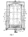
- FIGURE 1 is an illustrative plan view of an assembly of container fixtures according to the invention, in the chamber of a bell type closed atmosphere furnace shown in vertical cross-section;
- FIGURE la and lb are views of similar container fixtures;
- FIGURE 2 is a top view of the assembly taken on lines 2-2 of FIGURE 1;
- FIGURES 2a and 2b are top views of the respective container fixtures of FIGURES la and lb;
- FIGURE 3 is a perspective view of an atmosphere flow baffle fixture according to the invention,
- FIGURE 4 is a top view of loaded container fixtures, and
- FIGURE 5 is a facsimile micrograph of a metal specimen according to the invention.
- Referring to Figures 1 and 2 of the drawing showing a preferred embodiment of the container fixtures, the
assembly 10 of upright open-ended container fixtures 11 is made up of bottom A, middle B, and top C layers of uniform cross-section, in stacked relation..Each layer in turn includes matching or mirror-image pairs of quadrilateral container fixtures, one middle pair 11R rectilinear and the other outside pair 11T trapezoidal. The cooperating pairs 11R and 11T are configured to fit together side-by-side for a substantially gas-tight fit (as best seen in Figure 2) such'that forced convection gas flow through the furnace is tunneled downwardly inside, rather than outside, the fixtures. The fixtures are constructed with suitable durable material such as high temperature alloy metal and preferably stainless steel. Thewalls 12 are solid, that is imperforate, and thebase 13 contains apertures for passage therethrough of gas, as presently to be described. Stainless steel screen is suitable material for the base. Thus the fixtures 11 serve not only as containers to structurally support the charge of metal materials to be decarburized in the furnace, but also, when assembled together, as sectional conduits or tunnels through which the downward flow of decarburizing gas is uniformly distributed section-wise during the process. There is no limit to minimum or maximum charge density. However, advantageously, the assembly of segment loaded fixtures accommodates a charge density, for example, from about 150 to about 250, and preferably about 180, pounds per cubic foot or higher. Surprisingly, it is found that the loaded array of segments is uniform and permeable throughout the assembly, for purposes of the invention. Also, the loaded segments advantageously do not require mobilizing or mixing during the decarburizing process. Another preferred container fixture embodiment seen in Figures la and 2a is an open-ended annular container 11 with an inside cylindrical wall lla which is concentric with the top surface of the plenumtop wall 26. Still another preferred container fixture embodiment seen in Figures lb and 2b is an annular assembly of two matching open-ended container segments 11 adapted for axial flow registry with theinlet ports 28 of aplenum chamber 25. - The decarburizing furnace 20 (Figure 1) is of a type described in the above-mentioned U.S. Patent 3,081,074. It includes a
furnace bell 21,radiant heating tubes 22, abase 23, afan 24, and aplenum chamber 25 with plenumtop wall 26 andbottom wall 27. Theplenum top wall 26 contains plenum inlet ports 28 (as seen in dotted outline in Figure 2) and the bottom wall contains aplenum outlet port 29. - The
cylindrical zone 30 enclosed by thebell 21 andbase 23 makes for confined high temperature heating of charges inside the bell. A closed-top congruentinner cover 32 defining a furnace chamber orretort 34 is provided inzone 30 for gas-tight fitting upon thebase 23 by suitable means such as water/oil seal 35. The atmosphere can be controllably altered by introduction or withdrawal of gases at the inlet andoutlet port 31. The furnace bell and cover each retract from the base and are lifted for purposes of loading and unloading furnace charges. - For operation of the furnace with the
bell 21 andcover 32 retracted, the containers 11 are loaded with a furnace charge of scrap steel segments, the bell and cover are replaced, and the closed furnace is cycled through a pre-heat, a decarburizing soak, and finally steps of'cooling, opening and unloading. For loading, according to a preferred embodiment of the invention, the containers of the middle pair 11R of each layer are each first fitted with a baffle fixture 14 (Figure 3) positioned as illustrated in Figure 2 so that when loaded withmetal segments 15 as illustrated in Figure 4 the load is spaced away from the axial center of the respective layer. All containers are then loaded, partly or fully as desired, with segments to provide in each fixture a uniformly gas-permeable array of the segments, it being understood that the steady state pressure drop through the depth of the bed should be substantially uniform for each and all fixtures, and for each stack of fixtures. In other words, the loading is such that the axial gas flow through the charge is even and uniform thereby avoiding channeling effects which would cause axially and radially spaced pockets or zones of uneven decarburization. Random loading of each fixture is ordinarily sufficient to achieve even distribution of the segments in the fixture. Nesting of-the segments should be avoided where possible. The bottom layer A is then assembled on the plenumtop wall 26 so that each fixture is tightly fitted against the others and is in registry with the respectiveplenum inlet ports 28. Next, the middle layer B and top layer C are each placed, in turn, in stacked fashion onto and in registry with its respective underlying layer to provide the complete assembly illustrated in Figure 1. - Next, the
cover 32 andbell 21 are replaced. The furnace is then cycled through pre-soak, soak and cooling phases. The cycle time is a function of furnace size, furnace power, charge weight and density, for example, as follows:
chamber 33 is purged with dry nitrogen at 500 cubic feet per hour (CFH) for two hours while heating to 1300°F. The gas flow is accomplished under convection forced by thefan 24 which blows gas into theannular space 30 upwardly to the top of thecontainer assembly 10 and then downwardly in axial downdraft fashion through the loaded container fixtures 11 to theplenum chamber 25 by way of theinlet ports 28 and radially inward to theplenum outlet 29 andfan 24, thus completing the convection flow cycle. For the soak phase at decarburizing temperature, given a chamber unit volume of about 80 cubic feet and average charge density of 165-180 pounds per cubic foot, the atmosphere is cycled in succession through a natural (DX) gas purge for one hour, a DX gas soak with steam injection for 18 hours, and a nitrogen purge for one hour. In particular, the DX gas purge is done at a flow rate of about 250 CFH and at low dewpoint, e.g., 60°F. or less. The DX gas soak is done at the same flow rate, first at low entering dewpoint followed by an increasing dewpoint, e.g., from 69°F. (2.5% H20 by volume) to about 85°F. exhaust dewpoint (4% H20 by volume). The nitrogen purge is done at 500 CFH. A preferred decarburizing process gas is the so-called rich exothermic gas (Rich EXO: American Gas Association Class 102, air-to-DX gas ratio, about 6.5:1). Theoretical analysis of the soak atmosphere is the following: H20 - 2.5%, H2 -11%, CO - 8.6%, C02 - 6.4%, N2 - balance. For the cooling phase, the retort is pulled, and the charge is moved to a cooling stand and cooled preferably at ambient temperature. In a preferred procedure, the cooling is carried out by subjecting the charge to a dry nitrogen purge at 250 CFH such that the charge is cooled to about 200°F. in three hours. The resulting ferrous metal segments according to the invention typically have the following maximum and preferred weight per cent specifications:
- The invention is applicable broadly to steel scrap segments. The average carbon content will ordinarily be at least 0.05% by weight and preferably not more than about 0.2%. The segments can have any of a wide variety of shapes and sizes but generally expressed in terms of finished segments the width will be at least about one inch and the thickness at least about .062 gage. Especially if bulky or rigid, the segments will have a maximum dimension of about eight inches. Nesting of the segments ordinarily is not a problem. Desirably, the segments may be washed or degreased, and dried prior to decarburizing. Unlike the prior art surface-decarburized non-particulate ferrous metal, the segments decarburized according to the invention are unique, as indicated, in that each segment has a generally uniform carbon content. In other words, the carbon content is lowered not only at the surface but at the core and throughout the segment, the average being less than about 0.04%. The segments typically are soft and have the grain structure illustrated by Figure 5 showing the micrograph of a core-decarburized product specimen of the process of the invention using 2% Nital etchant at 400X magnification. The segments thus have significant advantage as uniformly high quality melt stock for specialty steel making and other purposes. The invention contemplates melting the decarburized segments of the invention by means which may be conventional to obtain quality ingots, castings or other forms for remelting, re-rolling or other purposes.
- While the invention has been described in detail, it will be realized by those skilled in the art that considerable variation can be made in such detail without departing from the spirit of the invention as hereinafter claimed.
Claims (20)
Priority Applications (1)
| Application Number | Priority Date | Filing Date | Title |
|---|---|---|---|
| AT82107372T ATE34777T1 (en) | 1982-02-01 | 1982-08-12 | TREATED FERROUS METALS AND METHODS FOR THEIR TREATMENT. |
Applications Claiming Priority (2)
| Application Number | Priority Date | Filing Date | Title |
|---|---|---|---|
| US34446982A | 1982-02-01 | 1982-02-01 | |
| US344469 | 1982-02-01 |
Publications (3)
| Publication Number | Publication Date |
|---|---|
| EP0085136A2 true EP0085136A2 (en) | 1983-08-10 |
| EP0085136A3 EP0085136A3 (en) | 1984-03-21 |
| EP0085136B1 EP0085136B1 (en) | 1988-06-01 |
Family
ID=23350664
Family Applications (1)
| Application Number | Title | Priority Date | Filing Date |
|---|---|---|---|
| EP19820107372 Expired EP0085136B1 (en) | 1982-02-01 | 1982-08-12 | Processed ferrous metal and process of production |
Country Status (4)
| Country | Link |
|---|---|
| EP (1) | EP0085136B1 (en) |
| AT (1) | ATE34777T1 (en) |
| CA (1) | CA1204944A (en) |
| DE (2) | DE85136T1 (en) |
Cited By (1)
| Publication number | Priority date | Publication date | Assignee | Title |
|---|---|---|---|---|
| EP0849555A1 (en) * | 1996-12-17 | 1998-06-24 | Shinko Pantec Co., Ltd. | Furnace for firing a glasslined product |
Citations (9)
| Publication number | Priority date | Publication date | Assignee | Title |
|---|---|---|---|---|
| USRE21500E (en) * | 1940-07-02 | Method of decarbonizing a carbon | ||
| US2311344A (en) * | 1941-03-04 | 1943-02-16 | Adolph W Machlet | Means for bathing workpieces in a controlled atmosphere |
| FR981416A (en) * | 1943-04-05 | 1951-05-25 | Process for the solid-state decarburization of carbon steels and certain stainless steels, resulting products and their applications | |
| GB753001A (en) * | 1953-11-30 | 1956-07-18 | Chromium Mining & Smelting Cor | Improvements in or relating to tray structure for holding a furnace charge |
| US3081074A (en) * | 1957-12-19 | 1963-03-12 | Lee Wilson | Apparatus for annealing coils of strip metal |
| US3127289A (en) * | 1964-03-31 | hoursx | ||
| US3196054A (en) * | 1963-08-14 | 1965-07-20 | Armco Steel Corp | Process of decarburizing and annealing of open coil silicon-iron sheet stock without intervening surface treatment |
| GB1149133A (en) * | 1966-10-27 | 1969-04-16 | Ver Deutsche Metallwerke Ag | Process for melting and decarburising steel scrap |
| US4272306A (en) * | 1979-09-27 | 1981-06-09 | Caterpillar Tractor Co. | Carburizing tub apparatus and method |
-
1982
- 1982-08-12 AT AT82107372T patent/ATE34777T1/en active
- 1982-08-12 DE DE198282107372T patent/DE85136T1/en active Pending
- 1982-08-12 DE DE8282107372T patent/DE3278570D1/en not_active Expired
- 1982-08-12 EP EP19820107372 patent/EP0085136B1/en not_active Expired
- 1982-08-19 CA CA000409765A patent/CA1204944A/en not_active Expired
Patent Citations (9)
| Publication number | Priority date | Publication date | Assignee | Title |
|---|---|---|---|---|
| USRE21500E (en) * | 1940-07-02 | Method of decarbonizing a carbon | ||
| US3127289A (en) * | 1964-03-31 | hoursx | ||
| US2311344A (en) * | 1941-03-04 | 1943-02-16 | Adolph W Machlet | Means for bathing workpieces in a controlled atmosphere |
| FR981416A (en) * | 1943-04-05 | 1951-05-25 | Process for the solid-state decarburization of carbon steels and certain stainless steels, resulting products and their applications | |
| GB753001A (en) * | 1953-11-30 | 1956-07-18 | Chromium Mining & Smelting Cor | Improvements in or relating to tray structure for holding a furnace charge |
| US3081074A (en) * | 1957-12-19 | 1963-03-12 | Lee Wilson | Apparatus for annealing coils of strip metal |
| US3196054A (en) * | 1963-08-14 | 1965-07-20 | Armco Steel Corp | Process of decarburizing and annealing of open coil silicon-iron sheet stock without intervening surface treatment |
| GB1149133A (en) * | 1966-10-27 | 1969-04-16 | Ver Deutsche Metallwerke Ag | Process for melting and decarburising steel scrap |
| US4272306A (en) * | 1979-09-27 | 1981-06-09 | Caterpillar Tractor Co. | Carburizing tub apparatus and method |
Cited By (1)
| Publication number | Priority date | Publication date | Assignee | Title |
|---|---|---|---|---|
| EP0849555A1 (en) * | 1996-12-17 | 1998-06-24 | Shinko Pantec Co., Ltd. | Furnace for firing a glasslined product |
Also Published As
| Publication number | Publication date |
|---|---|
| DE3278570D1 (en) | 1988-07-07 |
| DE85136T1 (en) | 1984-04-12 |
| CA1204944A (en) | 1986-05-27 |
| EP0085136B1 (en) | 1988-06-01 |
| ATE34777T1 (en) | 1988-06-15 |
| EP0085136A3 (en) | 1984-03-21 |
Similar Documents
| Publication | Publication Date | Title |
|---|---|---|
| US2543708A (en) | Heat-treating furnace | |
| US2543710A (en) | Process for producing insulating iron oxide coatings | |
| US6814573B2 (en) | Vacuum heat-treatment apparatus | |
| US2411073A (en) | Making products of iron or iron alloys | |
| US4781580A (en) | Indirectly heated rotary tubular kiln | |
| US4790750A (en) | Automated flexible installation for a rapid thermochemical treatment | |
| US4497671A (en) | Processed ferrous metal and process of production | |
| US4160680A (en) | Vacuum carburizing | |
| CN110904313A (en) | Box type natural gas spheroidizing annealing process | |
| EP0085136A2 (en) | Processed ferrous metal and process of production | |
| US4025610A (en) | Method and apparatus for denitrifying coke | |
| US4223874A (en) | Shaft furnace for producing low-oxygen iron-base metallic powder for powder metallurgy | |
| US4280807A (en) | Autoclave furnace with cooling system | |
| US4314790A (en) | Method of and device for shipping hot metal goods | |
| US3971679A (en) | Method of annealing oriented silicon steel | |
| CN108048686A (en) | A kind of vacuum drying oven prepares ferrovanadium nitride method | |
| US4207120A (en) | Production of metal compacts | |
| US3053523A (en) | Inner cover for box annealing furnace | |
| US3824122A (en) | Continuous diffusion coating | |
| US4175921A (en) | Apparatus for removing gases from particles | |
| US3746584A (en) | Method for the continuous vacuum decarbonization of low carbon ferrochrome | |
| JPH0645801B2 (en) | Finishing heat treatment method for Cr alloy steel powder | |
| RU2144170C1 (en) | Container for acid-free structural annealing of forcings | |
| US3096174A (en) | Methods of reducing a metal oxide by a carbonaceous material at sub-atmospheric pressures | |
| JP2828517B2 (en) | Ceramic firing container |
Legal Events
| Date | Code | Title | Description |
|---|---|---|---|
| PUAI | Public reference made under article 153(3) epc to a published international application that has entered the european phase |
Free format text: ORIGINAL CODE: 0009012 |
|
| AK | Designated contracting states |
Designated state(s): AT BE CH DE FR GB IT LI LU NL SE |
|
| TCNL | Nl: translation of patent claims filed | ||
| PUAL | Search report despatched |
Free format text: ORIGINAL CODE: 0009013 |
|
| ITCL | It: translation for ep claims filed |
Representative=s name: MODIANO & ASSOCIATI S.R.L. |
|
| EL | Fr: translation of claims filed | ||
| TCAT | At: translation of patent claims filed | ||
| AK | Designated contracting states |
Designated state(s): AT BE CH DE FR GB IT LI LU NL SE |
|
| DET | De: translation of patent claims | ||
| 17P | Request for examination filed |
Effective date: 19840702 |
|
| 17Q | First examination report despatched |
Effective date: 19860421 |
|
| GRAA | (expected) grant |
Free format text: ORIGINAL CODE: 0009210 |
|
| AK | Designated contracting states |
Kind code of ref document: B1 Designated state(s): AT BE CH DE FR GB IT LI LU NL SE |
|
| REF | Corresponds to: |
Ref document number: 34777 Country of ref document: AT Date of ref document: 19880615 Kind code of ref document: T |
|
| REF | Corresponds to: |
Ref document number: 3278570 Country of ref document: DE Date of ref document: 19880707 |
|
| ET | Fr: translation filed | ||
| ITF | It: translation for a ep patent filed |
Owner name: MODIANO & ASSOCIATI S.R.L. |
|
| PLBE | No opposition filed within time limit |
Free format text: ORIGINAL CODE: 0009261 |
|
| STAA | Information on the status of an ep patent application or granted ep patent |
Free format text: STATUS: NO OPPOSITION FILED WITHIN TIME LIMIT |
|
| 26N | No opposition filed | ||
| ITTA | It: last paid annual fee | ||
| PGFP | Annual fee paid to national office [announced via postgrant information from national office to epo] |
Ref country code: GB Payment date: 19920812 Year of fee payment: 11 |
|
| PGFP | Annual fee paid to national office [announced via postgrant information from national office to epo] |
Ref country code: DE Payment date: 19920824 Year of fee payment: 11 |
|
| PGFP | Annual fee paid to national office [announced via postgrant information from national office to epo] |
Ref country code: SE Payment date: 19920826 Year of fee payment: 11 Ref country code: CH Payment date: 19920826 Year of fee payment: 11 |
|
| PGFP | Annual fee paid to national office [announced via postgrant information from national office to epo] |
Ref country code: FR Payment date: 19920827 Year of fee payment: 11 Ref country code: AT Payment date: 19920827 Year of fee payment: 11 |
|
| PGFP | Annual fee paid to national office [announced via postgrant information from national office to epo] |
Ref country code: NL Payment date: 19920831 Year of fee payment: 11 |
|
| PGFP | Annual fee paid to national office [announced via postgrant information from national office to epo] |
Ref country code: LU Payment date: 19920909 Year of fee payment: 11 |
|
| PGFP | Annual fee paid to national office [announced via postgrant information from national office to epo] |
Ref country code: BE Payment date: 19920930 Year of fee payment: 11 |
|
| EPTA | Lu: last paid annual fee | ||
| PG25 | Lapsed in a contracting state [announced via postgrant information from national office to epo] |
Ref country code: LU Free format text: LAPSE BECAUSE OF NON-PAYMENT OF DUE FEES Effective date: 19930812 Ref country code: GB Effective date: 19930812 Ref country code: AT Effective date: 19930812 |
|
| PG25 | Lapsed in a contracting state [announced via postgrant information from national office to epo] |
Ref country code: SE Effective date: 19930813 |
|
| PG25 | Lapsed in a contracting state [announced via postgrant information from national office to epo] |
Ref country code: LI Effective date: 19930831 Ref country code: CH Effective date: 19930831 Ref country code: BE Effective date: 19930831 |
|
| BERE | Be: lapsed |
Owner name: ALLIED IRON CY Effective date: 19930831 |
|
| PG25 | Lapsed in a contracting state [announced via postgrant information from national office to epo] |
Ref country code: NL Effective date: 19940301 |
|
| GBPC | Gb: european patent ceased through non-payment of renewal fee |
Effective date: 19930812 |
|
| NLV4 | Nl: lapsed or anulled due to non-payment of the annual fee | ||
| PG25 | Lapsed in a contracting state [announced via postgrant information from national office to epo] |
Ref country code: FR Effective date: 19940429 |
|
| REG | Reference to a national code |
Ref country code: CH Ref legal event code: PL |
|
| PG25 | Lapsed in a contracting state [announced via postgrant information from national office to epo] |
Ref country code: DE Effective date: 19940503 |
|
| REG | Reference to a national code |
Ref country code: FR Ref legal event code: ST |
|
| EUG | Se: european patent has lapsed |
Ref document number: 82107372.3 Effective date: 19940310 |