EP0085496B1 - Transducer supporting and contacting means - Google Patents
Transducer supporting and contacting means Download PDFInfo
- Publication number
- EP0085496B1 EP0085496B1 EP83300204A EP83300204A EP0085496B1 EP 0085496 B1 EP0085496 B1 EP 0085496B1 EP 83300204 A EP83300204 A EP 83300204A EP 83300204 A EP83300204 A EP 83300204A EP 0085496 B1 EP0085496 B1 EP 0085496B1
- Authority
- EP
- European Patent Office
- Prior art keywords
- transducer
- housing
- supporting
- contacting means
- contact
- Prior art date
- Legal status (The legal status is an assumption and is not a legal conclusion. Google has not performed a legal analysis and makes no representation as to the accuracy of the status listed.)
- Expired
Links
- 239000002184 metal Substances 0.000 claims description 15
- 229910052751 metal Inorganic materials 0.000 claims description 15
- 239000000919 ceramic Substances 0.000 claims description 9
- 230000008878 coupling Effects 0.000 claims description 8
- 238000010168 coupling process Methods 0.000 claims description 8
- 238000005859 coupling reaction Methods 0.000 claims description 8
- 239000004033 plastic Substances 0.000 claims description 6
- 239000000463 material Substances 0.000 claims 2
- 230000013011 mating Effects 0.000 claims 1
- 238000013016 damping Methods 0.000 description 5
- 239000000853 adhesive Substances 0.000 description 4
- 230000001070 adhesive effect Effects 0.000 description 4
- 230000000694 effects Effects 0.000 description 4
- 230000010355 oscillation Effects 0.000 description 3
- 238000003462 Bender reaction Methods 0.000 description 2
- HCHKCACWOHOZIP-UHFFFAOYSA-N Zinc Chemical compound [Zn] HCHKCACWOHOZIP-UHFFFAOYSA-N 0.000 description 2
- 238000004519 manufacturing process Methods 0.000 description 2
- 229910052725 zinc Inorganic materials 0.000 description 2
- 239000011701 zinc Substances 0.000 description 2
- 238000004026 adhesive bonding Methods 0.000 description 1
- 239000007767 bonding agent Substances 0.000 description 1
- 239000011231 conductive filler Substances 0.000 description 1
- 239000004020 conductor Substances 0.000 description 1
- 230000007423 decrease Effects 0.000 description 1
- 230000014759 maintenance of location Effects 0.000 description 1
- 229920002379 silicone rubber Polymers 0.000 description 1
- 239000000779 smoke Substances 0.000 description 1
- 238000005476 soldering Methods 0.000 description 1
Images


Classifications
-
- H—ELECTRICITY
- H04—ELECTRIC COMMUNICATION TECHNIQUE
- H04R—LOUDSPEAKERS, MICROPHONES, GRAMOPHONE PICK-UPS OR LIKE ACOUSTIC ELECTROMECHANICAL TRANSDUCERS; DEAF-AID SETS; PUBLIC ADDRESS SYSTEMS
- H04R17/00—Piezoelectric transducers; Electrostrictive transducers
-
- H—ELECTRICITY
- H04—ELECTRIC COMMUNICATION TECHNIQUE
- H04R—LOUDSPEAKERS, MICROPHONES, GRAMOPHONE PICK-UPS OR LIKE ACOUSTIC ELECTROMECHANICAL TRANSDUCERS; DEAF-AID SETS; PUBLIC ADDRESS SYSTEMS
- H04R2499/00—Aspects covered by H04R or H04S not otherwise provided for in their subgroups
- H04R2499/10—General applications
- H04R2499/11—Transducers incorporated or for use in hand-held devices, e.g. mobile phones, PDA's, camera's
Definitions
- the present invention relates to supporting and contacting means for a piezoelectric audio transducer, and particularly to nodal mounting means.
- Piezoelectric audio transducers also known as piezoceramic benders or benders, are enclosed in a housing or holder of some kind and the combination is known as a buzzer. Buzzers presently find use in telephones, electronic games, home appliances, smoke detectors, radar detectors, intrusion alarms, and medical equipment.
- the transducers are generally mounted in one of three ways: center mount, edge mount, and nodal mount. Nodal mounts are required when maximum sound pressure levels are to be achieved with the minimum transducer drive current since mounting of the transducer at its nodal diameter does not dampen oscillations. Center mounts and edge mounts produce a higher impedance and a lower frequency, and are used where mechanical considerations are more important than electrical, or where it is desirable to force the transducer to vibrate at a frequency lower than its resonant frequency.
- the annular surface constitutes a nodal mount when it is a ring of a specific diameter where the natural vibration of the bender exhibits a node, which permits oscillations of greater amplitude than mounting at the outer edge, the center, or any other radius.
- Several buzzer manufacturers use an adhesive to mount the transducer to a ring in a housing, and the necessary electrical contacts are made by soldering fine wires to the opposite surface on the wafer of piezoelectric ceramic, and the metal surface surrounding the wafer.
- An alternative to soldered wire is a pressure contact employing resilient metal contacts extending from a housing member which mounts to the housing containing the ring.
- the buzzer disclosed in U.S.A. 4 230 383 employs adhesive such as silicon rubber to adhere the ring to the first surface of the transducer and resilient contacts bearing on the second surface.
- adhesive such as silicon rubber
- a similar example is a buzzer manufactured by BRK Electronics; this employs an adhesive ring mount on the node of the all-metal surface of the transducer, two resilient contacts against the ceramic on the node opposite the ring mount, and a third contact outside the node.
- An alternative nodal mounting scheme exemplified by a buzzer manufactured by Molex, Inc., utilizes housing members with rings which bear against the node on opposite surfaces. Electrical contact is achieved by resilient contacts, mounted in one housing member, which bear against the surface having the ceramic.
- US-A-4 063 049 and DE-A-2 951 396 disclose supporting and contacting means for a piezoelectric audio transducer, said transducer being in the form of a circular metal wafer having a first all metal surface and an opposed second surface having a piezoelectric ceramic bonded thereto, said supporting and contacting means being of the type comprising a housing having an annular surface therein, said annular surface contacting said first surface of said transducer, said supporting and contacting means further comprising first and second electrical contacts in contact with said second surface thereof.
- DE-A-2 951 396 also discloses that the transducer is supported by being clamped resiliently between the top annular surface and the first and second electrical contacts and that the housing is profiled closely to receive the transducer so that the annular surface is concentric relative to the outer edge of the transducer.
- supporting and contacting means for a piezoelectric audio transducer said transducer being in the form of a circular metal wafer having a first all metal surface and an opposed second surface having a piezoelectric ceramic bonded thereto, said supporting and contacting means being of the type comprising a housing having an annular surface therein, said annular surface contacting said first surface of said transducer, said supporting and contacting means further comprising first and second electrical contacts in contact with said second surface thereof, said transducer being supported by being clamped resiliently between the top annular surface and the first and second electrical contacts, said housing being profiled to closely receive said transducer so that the annular surface is concentric relative to the outer edge of the transducer, said supporting and contact means is characterised in that said first contact is mounted on a part-circular wall having a top surface in a plane which parallels the transducer, said part-circular wall being fixed to a board member to which said housing is resiliently attached, said part-circular wall defining a gap where said first contact is mounted
- the present invention provides a nodal mounting and contacting scheme with minimum damping.
- Two points of independent contact are mounted on a board and contact the transducer on isolated sections of the piezoelectric wafer.
- One of the contacts is situated on the top surface of a semicircular wall which forms a resonant cavity and the other is mounted in the aperture defined by the wall.
- a conductive annular surface or ring contact borne by or an integral part of a housing bears against the opposite all-metal surface of the transducer and holds it against the board-mounted contacts.
- the housing is resiliently mounted to the board and has an orienting rib which mates with a notch in the edge of the transducer to establish angular orientation of the contacts and the sections of the piezoelectric wafer.
- An alternative embodiment utilizes a plastic housing having a top portion profiled with slots for resilience of the annular surface and legs which snap directly into the circuit board; one contact is located off the node at a point on the bender where resonant frequency is affected at a minimum.
- the ring contact is formed on the plastic housing, so all electrical contact is via board-mounted contacts.
- the board-mounted contacts are particularly well suited to being die cast in metal such as zinc which is anchored through holes in the board and may form an integral part of circuit conductors.
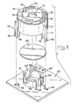
- FIG. 1 shows the housing 10 and transducer 30 exploded from the components mounted to circuit board 40, which include the coupling members 46, part-circular wall 59, and center post 65.
- Salient features of the housing 10 are the inner cylindrical surface 12, outer cylindrical surface 13, and top portion 14.
- the top portion 14 carries a tubular member 15 which is concentric with inner cylindrical surface 12.
- the top surface has an inner aperture 17 which communicates with the inside of tubular member 15, and outer apertures 18 which communicate with the space between the inner surface 12 and tubular member 15.
- the inner surface 12 has an orienting rib 20 thereon which cooperates with notch 36 in the transducer 30 as will be described.
- the outer surface 13 has hand grip ribs 24 thereon, a bottom flange 25, and locating keys 26 which hold leaf springs 27 in angular alignment around housing 10.
- a notch 28 in each leaf spring 27 serves a retaining and centering function with the respective coupling member 46 as will be described.
- a part-circular wall 59 having a flat top surface 60 and parallel sidewalls 63 defining a gap 62 is mounted to board member 40, which is parallel to the plane of top surface 60.
- a first contact or stud 61 is situated on the top surface 60 directly across from the gap 62, and a second contact or stud 66 is situated on center post 65 which is mounted to board member 40 in the middle of gap 62.
- the studs 61, 66 are the same distance above the board member 40.
- the part-circular wall 59 is widest at sidewalls 63; this is because the area of sidewalls 63 and volume therebetween are critical parameters in the design of an aperture for a resonant cavity for a piezoelectric audio transducer 30.
- the resonant cavity is the volume within the part-circular wall 59.
- An important feature of the wall 59 is that it is of the same diameter as the node exhibited by the natural vibration of the transducer 30.
- Each coupling member 46 is characterized by a bottom plate 47 mounted to board member 40, and an outer wall 50 and end wall 54 which are perpendicular to bottom plate 47.
- the outer wall 50 has an inverted ramp member 52 integral therewith which has an apex 53 facing bottom plate 47.
- the bottom plates 47 have arcuate surfaces 48 facing inward which are profiled to closely receive the bottom flange 25, and core holes 49 which communicate with like profiled holes in the board member 40.
- the housing 10 is assembled to board member 40 by placing the transducer 30 in the housing 10 so that the rib 20 fits in notch 36, inserting springs 27 into slots 23 on each side of each locating key 26, placing the housing 10 over wall 59 such that extension 21 of rib 20 fits in cut-out 41 in board 40, and rotating the housing 10 so that leaf springs 27 slide under ramps 52 until the notches 28 mate with apices 53.
- Figure 2 depicts the second surface 32 of transducer 30.
- This is a typical transducer design incorporating a wafer of piezoelectric ceramic 33 bonded to surface 32.
- a feedback portion 34 of like ceramic is isolated from the rest of the wafer 33.
- the transducer 30 is distinguished by notch 36 which receives orienting rib 20 ( Figure 1) in the housing 10; this assures that the feedback portion 34 will contact second contact or stud 66.
- the diameter of the wafer 33 is larger than that of the part-circular wall 59, which corresponds to the resonant node of the transducer, so that first contact or stud 61 will contact the wafer 33 on the node of the transducer 30.
- Figure 3 is a cross section of the housing 10 as assembled to board 40 with the transducer 30 sandwiched against studs 61, 66.
- First surface 31 of the transducer 30 is borne against by annular surface 16 which defines the lower end of tubular member 15.
- the lower end of tubular member 15 has a beveled edge so that the annular surface 16 approximates a circular line.
- the diameter of the tubular member 15, like that of the semicircular wall 59, corresponds to the resonant node of the transducer.
- the contacting arrangement shown being confined to the resonant node of the transducer, has a minimum damping effect when current is applied to the transducer and thus permits the greatest possible acoustic efficiency for a given resonant cavity design.
- the transducer 30 is spaced slightly from the inner surface 12 of housing 10 by spacing ribs 22 on the inner surface 12.
- the spacing ribs 22 have a lower profile than orienting rib 20 and serve only to center the transducer 30 so that annular surface 16 and studs 61, 66 contact the transducer on the resonant node.
- the ribs 22 are spaced about 120° apart opposite hand grip ribs 24 and define the perimeter of a circle only very slightly larger than the transducer, whereby centering of the transducer is accomplished without edge damping. Note that the leaf springs 27 are flexed slightly to resiliently clamp the transducer between the annular surface 16 and studs 61, 66.
- the coupling members 46, part-circular wall 59, and center post 65 are mounted to board member 40 by rivets 56, 64, and 67 respectively. These may be cast through using a metal such as zinc to manufacture the board-mounted components inexpensively.
- the core hole 49 and core hole 42 in the board 40 permit entry of a core member to form the ramp member 52.
- the housing 10 may be cast separately or a modified version stamped and formed from sheet metal.
- the rivets 56, 64, 67 are continuous with circuit traces cast on the bottom surface 44 of board member 40.
- Two independent points of electrical contact may be established for applying an alternating or pulsed direct current across the wafer, via annular surface 16 and first contact or stud 61, and a third point of electrical contact may be established for a feedback lead, via second contact or stud 66.
- Figure 4 is a plan view of the inside of housing 10 and shows the orienting rib 20 and spacing ribs 22 to best advantage.
- the orienting rib 20 extends below the housing and enters cut-out 41 in the board member 40 ( Figure 1). This assures that the housing will mate to the coupling members 46 in only one orientation, to assure proper contact of studs 61, 66 with the wafer 33 and feedback portion 34 respectively.
- FIG 5 shows an alternative embodiment of the invention which employs a different housing 70.
- the housing 70 is plastic and thus cannot provide electrical contact through the annular surface 16 (not shown) formed on the edge of a tubular member 15 carried therein, which is structurally like member 15 of the first described embodiment (see Figures 3 and 4).
- This embodiment comprises two electrically isolated semicircular walls 59, 59' separated by gaps 62, 62'. Sidewalls 63, 63' are dimensioned to collectively satisfy the equation for a Helmholtz resonator.
- Wall 59' has an offset portion 58' having a contact stud 61' thereon which is slightly higher than studs 61,66 (by the thickness of wafer 33) in order to contact second surface 32 outside the diameter of wafer 33 so that alternating or pulsed direct current can be applied across the wafer 33 while retaining post 65 for feedback purposes.
- the resilient plastic housing 70 may be metalized or otherwise made conductive by conductive fillers so that the tubular member 15 in the housing may serve as a third electrical contact as in the first described embodiment, so that nodal contact only is possible.
- the housing 70 of Figure 5 is characterized by an inner cylindrical surface 72, an outer cylindrical surface 73, and a top portion 74 having overlapping arcuate slots 75 therein which define strips 76 therebetween.
- the strips 76 provide resilience between the inner surface 72 and the tubular member for resilient clamping of the transducer between contacts 61, 66.
- Legs 77 on the outside 73 of the housing have latches 78 which snap resiliently into holes 45 in the board for retention.
- the bottom edge 79 of the housing 70 will be spaced above the board 40 by the spring action of the top portion 74 against the transducer. The bottom edge 79 prevents overtravel of housing 70 if the housing receives a blow or is otherwise mishandled.
- slots 75 also act as apertures for the outer resonant cavity contained in the housing, while the hole 71 acts as the aperture for the inner resonant cavity contained by the tubular member.
- the board mount components shown for this and other embodiments may be soldered or mechanically fixed to the board as an alternative to being die cast.
Description
- The present invention relates to supporting and contacting means for a piezoelectric audio transducer, and particularly to nodal mounting means.
- Piezoelectric audio transducers, also known as piezoceramic benders or benders, are enclosed in a housing or holder of some kind and the combination is known as a buzzer. Buzzers presently find use in telephones, electronic games, home appliances, smoke detectors, radar detectors, intrusion alarms, and medical equipment. The transducers are generally mounted in one of three ways: center mount, edge mount, and nodal mount. Nodal mounts are required when maximum sound pressure levels are to be achieved with the minimum transducer drive current since mounting of the transducer at its nodal diameter does not dampen oscillations. Center mounts and edge mounts produce a higher impedance and a lower frequency, and are used where mechanical considerations are more important than electrical, or where it is desirable to force the transducer to vibrate at a frequency lower than its resonant frequency.
- There is described in U.S.A. 4,230,383 supporting and contacting means for a piezoelectric audio transducer, said transducer being in the form of a circular metal wafer having a first all metal surface and an opposed second surface having a piezoelectric ceramic bonded thereto, said supporting and contacting means being of the type comprising a housing having an annular surface therein, said annular surface contacting said first surface of said transducer, said supporting and contacting means further comprising first and second electrical contacts in contact with said second surface. The annular surface constitutes a nodal mount when it is a ring of a specific diameter where the natural vibration of the bender exhibits a node, which permits oscillations of greater amplitude than mounting at the outer edge, the center, or any other radius. Several buzzer manufacturers use an adhesive to mount the transducer to a ring in a housing, and the necessary electrical contacts are made by soldering fine wires to the opposite surface on the wafer of piezoelectric ceramic, and the metal surface surrounding the wafer. An alternative to soldered wire is a pressure contact employing resilient metal contacts extending from a housing member which mounts to the housing containing the ring.
- The buzzer disclosed in U.S.A. 4 230 383 employs adhesive such as silicon rubber to adhere the ring to the first surface of the transducer and resilient contacts bearing on the second surface. A similar example is a buzzer manufactured by BRK Electronics; this employs an adhesive ring mount on the node of the all-metal surface of the transducer, two resilient contacts against the ceramic on the node opposite the ring mount, and a third contact outside the node. An alternative nodal mounting scheme, exemplified by a buzzer manufactured by Molex, Inc., utilizes housing members with rings which bear against the node on opposite surfaces. Electrical contact is achieved by resilient contacts, mounted in one housing member, which bear against the surface having the ceramic. These are not nodal contacts, and thus have a damping effect on the vibration. Even fine wires soldered to the bender tend to dampen oscillations, which decreases efficiency and represents a costly hand operation in buzzer manufacture. It would be desirable to have a mounting and contacting means in which the mounting and electrical contacts necessary to drive the buzzer could be achieved solely on the nodes for maximum acoustical performance. It would be most desirable if adhesive could be eliminated, since adhesive bonding agents necessarily have a damping effect.
- US-A-4 063 049 and DE-A-2 951 396 disclose supporting and contacting means for a piezoelectric audio transducer, said transducer being in the form of a circular metal wafer having a first all metal surface and an opposed second surface having a piezoelectric ceramic bonded thereto, said supporting and contacting means being of the type comprising a housing having an annular surface therein, said annular surface contacting said first surface of said transducer, said supporting and contacting means further comprising first and second electrical contacts in contact with said second surface thereof.
- DE-A-2 951 396 also discloses that the transducer is supported by being clamped resiliently between the top annular surface and the first and second electrical contacts and that the housing is profiled closely to receive the transducer so that the annular surface is concentric relative to the outer edge of the transducer.
- In US-A-4 063 049 the support ring provides the sole support for the transducer, and one contact is mounted on the ring.
- It is an object to provide an improved supporting and contacting means for a piezoelectric audio transducer.
- According to the invention supporting and contacting means for a piezoelectric audio transducer, said transducer being in the form of a circular metal wafer having a first all metal surface and an opposed second surface having a piezoelectric ceramic bonded thereto, said supporting and contacting means being of the type comprising a housing having an annular surface therein, said annular surface contacting said first surface of said transducer, said supporting and contacting means further comprising first and second electrical contacts in contact with said second surface thereof, said transducer being supported by being clamped resiliently between the top annular surface and the first and second electrical contacts, said housing being profiled to closely receive said transducer so that the annular surface is concentric relative to the outer edge of the transducer, said supporting and contact means is characterised in that said first contact is mounted on a part-circular wall having a top surface in a plane which parallels the transducer, said part-circular wall being fixed to a board member to which said housing is resiliently attached, said part-circular wall defining a gap where said part-circular wall is incomplete, said second contact being mounted on a centre post fixed to said board member in said gap, said top surface generally paralleling the node of the transducer, whereby said part-circular wall forms a resonant cavity.
- The present invention provides a nodal mounting and contacting scheme with minimum damping. Two points of independent contact are mounted on a board and contact the transducer on isolated sections of the piezoelectric wafer. One of the contacts is situated on the top surface of a semicircular wall which forms a resonant cavity and the other is mounted in the aperture defined by the wall. A conductive annular surface or ring contact borne by or an integral part of a housing bears against the opposite all-metal surface of the transducer and holds it against the board-mounted contacts. The housing is resiliently mounted to the board and has an orienting rib which mates with a notch in the edge of the transducer to establish angular orientation of the contacts and the sections of the piezoelectric wafer. Spacing ribs orient the contacts on the node and space it from the inside wall of the housing, while maintaining the ring contact on the node of the transducer. An alternative embodiment utilizes a plastic housing having a top portion profiled with slots for resilience of the annular surface and legs which snap directly into the circuit board; one contact is located off the node at a point on the bender where resonant frequency is affected at a minimum. The ring contact is formed on the plastic housing, so all electrical contact is via board-mounted contacts. The board-mounted contacts are particularly well suited to being die cast in metal such as zinc which is anchored through holes in the board and may form an integral part of circuit conductors.
- Two embodiments of the invention will now be described by way of examples with reference to the accompanying drawings in which:
- FIGURE 1 is an exploded perspective;
- FIGURE 2 is a plan view of a transducer;
- FIGURE 3 is a side section of the assembly taken along line 3-3 of Figure 1;
- FIGURE 4 is a plan view of the inside of the housing member; and
- FIGURE 5 is an exploded perspective of an alternative embodiment.
- Figure 1 shows the
housing 10 andtransducer 30 exploded from the components mounted tocircuit board 40, which include thecoupling members 46, part-circular wall 59, andcenter post 65. Salient features of thehousing 10 are the innercylindrical surface 12, outercylindrical surface 13, andtop portion 14. Thetop portion 14 carries atubular member 15 which is concentric with innercylindrical surface 12. The top surface has aninner aperture 17 which communicates with the inside oftubular member 15, andouter apertures 18 which communicate with the space between theinner surface 12 andtubular member 15. Theinner surface 12 has anorienting rib 20 thereon which cooperates withnotch 36 in thetransducer 30 as will be described. Theouter surface 13 hashand grip ribs 24 thereon, abottom flange 25, and locatingkeys 26 which holdleaf springs 27 in angular alignment aroundhousing 10. Anotch 28 in eachleaf spring 27 serves a retaining and centering function with therespective coupling member 46 as will be described. - Referring still to Figure 1, a part-
circular wall 59 having aflat top surface 60 andparallel sidewalls 63 defining agap 62 is mounted toboard member 40, which is parallel to the plane oftop surface 60. A first contact orstud 61 is situated on thetop surface 60 directly across from thegap 62, and a second contact orstud 66 is situated oncenter post 65 which is mounted toboard member 40 in the middle ofgap 62. Thestuds board member 40. Note that the part-circular wall 59 is widest atsidewalls 63; this is because the area ofsidewalls 63 and volume therebetween are critical parameters in the design of an aperture for a resonant cavity for apiezoelectric audio transducer 30. The resonant cavity is the volume within the part-circular wall 59. An important feature of thewall 59 is that it is of the same diameter as the node exhibited by the natural vibration of thetransducer 30. - Also depicted in Figure 1 are three
coupling members 46, each spaced the same distance from the center ofsemicircular wall 59 and spaced about 120° apart. Eachcoupling member 46 is characterized by abottom plate 47 mounted toboard member 40, and anouter wall 50 andend wall 54 which are perpendicular tobottom plate 47. Theouter wall 50 has an invertedramp member 52 integral therewith which has anapex 53 facingbottom plate 47. Thebottom plates 47 havearcuate surfaces 48 facing inward which are profiled to closely receive thebottom flange 25, andcore holes 49 which communicate with like profiled holes in theboard member 40. Thehousing 10 is assembled toboard member 40 by placing thetransducer 30 in thehousing 10 so that therib 20 fits innotch 36, insertingsprings 27 intoslots 23 on each side of each locatingkey 26, placing thehousing 10 overwall 59 such thatextension 21 ofrib 20 fits in cut-out 41 inboard 40, and rotating thehousing 10 so thatleaf springs 27 slide underramps 52 until thenotches 28 mate withapices 53. - Figure 2 depicts the
second surface 32 oftransducer 30. This is a typical transducer design incorporating a wafer ofpiezoelectric ceramic 33 bonded tosurface 32. A feedback portion 34 of like ceramic is isolated from the rest of thewafer 33. Thetransducer 30 is distinguished bynotch 36 which receives orienting rib 20 (Figure 1) in thehousing 10; this assures that the feedback portion 34 will contact second contact orstud 66. The diameter of thewafer 33 is larger than that of the part-circular wall 59, which corresponds to the resonant node of the transducer, so that first contact orstud 61 will contact thewafer 33 on the node of thetransducer 30. - Figure 3 is a cross section of the
housing 10 as assembled toboard 40 with thetransducer 30 sandwiched againststuds First surface 31 of thetransducer 30 is borne against byannular surface 16 which defines the lower end oftubular member 15. The lower end oftubular member 15 has a beveled edge so that theannular surface 16 approximates a circular line. The diameter of thetubular member 15, like that of thesemicircular wall 59, corresponds to the resonant node of the transducer. The contacting arrangement shown, being confined to the resonant node of the transducer, has a minimum damping effect when current is applied to the transducer and thus permits the greatest possible acoustic efficiency for a given resonant cavity design. Thetransducer 30 is spaced slightly from theinner surface 12 ofhousing 10 by spacingribs 22 on theinner surface 12. Thespacing ribs 22 have a lower profile than orientingrib 20 and serve only to center thetransducer 30 so thatannular surface 16 andstuds ribs 22 are spaced about 120° apart oppositehand grip ribs 24 and define the perimeter of a circle only very slightly larger than the transducer, whereby centering of the transducer is accomplished without edge damping. Note that theleaf springs 27 are flexed slightly to resiliently clamp the transducer between theannular surface 16 andstuds - Referring still to Figure 3, the
coupling members 46, part-circular wall 59, and center post 65 are mounted toboard member 40 byrivets core hole 49 andcore hole 42 in theboard 40 permit entry of a core member to form theramp member 52. Thehousing 10 may be cast separately or a modified version stamped and formed from sheet metal. Therivets bottom surface 44 ofboard member 40. Two independent points of electrical contact may be established for applying an alternating or pulsed direct current across the wafer, viaannular surface 16 and first contact orstud 61, and a third point of electrical contact may be established for a feedback lead, via second contact orstud 66. - Figure 4 is a plan view of the inside of
housing 10 and shows the orientingrib 20 andspacing ribs 22 to best advantage. The orientingrib 20 extends below the housing and enters cut-out 41 in the board member 40 (Figure 1). This assures that the housing will mate to thecoupling members 46 in only one orientation, to assure proper contact ofstuds wafer 33 and feedback portion 34 respectively. - Figure 5 shows an alternative embodiment of the invention which employs a
different housing 70. Thehousing 70 is plastic and thus cannot provide electrical contact through the annular surface 16 (not shown) formed on the edge of atubular member 15 carried therein, which is structurally likemember 15 of the first described embodiment (see Figures 3 and 4). This embodiment comprises two electrically isolatedsemicircular walls 59, 59' separated bygaps 62, 62'.Sidewalls 63, 63' are dimensioned to collectively satisfy the equation for a Helmholtz resonator. Wall 59' has an offset portion 58' having a contact stud 61' thereon which is slightly higher thanstuds 61,66 (by the thickness of wafer 33) in order to contactsecond surface 32 outside the diameter ofwafer 33 so that alternating or pulsed direct current can be applied across thewafer 33 while retainingpost 65 for feedback purposes. This would dampen the vibration of thetransducer 30 slightly more than nodal contacts, but if located as shown in Figure 5 would have little effect. Alternatively, the resilientplastic housing 70 may be metalized or otherwise made conductive by conductive fillers so that thetubular member 15 in the housing may serve as a third electrical contact as in the first described embodiment, so that nodal contact only is possible. - The
housing 70 of Figure 5 is characterized by an innercylindrical surface 72, an outercylindrical surface 73, and atop portion 74 having overlappingarcuate slots 75 therein which definestrips 76 therebetween. Thestrips 76 provide resilience between theinner surface 72 and the tubular member for resilient clamping of the transducer betweencontacts Legs 77 on the outside 73 of the housing have latches 78 which snap resiliently intoholes 45 in the board for retention. Thebottom edge 79 of thehousing 70 will be spaced above theboard 40 by the spring action of thetop portion 74 against the transducer. Thebottom edge 79 prevents overtravel ofhousing 70 if the housing receives a blow or is otherwise mishandled. Note that theslots 75 also act as apertures for the outer resonant cavity contained in the housing, while thehole 71 acts as the aperture for the inner resonant cavity contained by the tubular member. The board mount components shown for this and other embodiments may be soldered or mechanically fixed to the board as an alternative to being die cast. - The above described embodiments are exemplary and not intended to limit the scope of the claims which follow.
Claims (9)
Applications Claiming Priority (2)
| Application Number | Priority Date | Filing Date | Title |
|---|---|---|---|
| US06/343,680 US4429247A (en) | 1982-01-28 | 1982-01-28 | Piezoelectric transducer supporting and contacting means |
| US343680 | 1994-11-22 |
Publications (3)
| Publication Number | Publication Date |
|---|---|
| EP0085496A2 EP0085496A2 (en) | 1983-08-10 |
| EP0085496A3 EP0085496A3 (en) | 1984-09-19 |
| EP0085496B1 true EP0085496B1 (en) | 1986-09-24 |
Family
ID=23347144
Family Applications (1)
| Application Number | Title | Priority Date | Filing Date |
|---|---|---|---|
| EP83300204A Expired EP0085496B1 (en) | 1982-01-28 | 1983-01-17 | Transducer supporting and contacting means |
Country Status (5)
| Country | Link |
|---|---|
| US (1) | US4429247A (en) |
| EP (1) | EP0085496B1 (en) |
| JP (1) | JPS58133100A (en) |
| CA (1) | CA1195419A (en) |
| DE (1) | DE3366352D1 (en) |
Cited By (1)
| Publication number | Priority date | Publication date | Assignee | Title |
|---|---|---|---|---|
| DE102013208801A1 (en) | 2013-05-14 | 2014-11-20 | Robert Bosch Gmbh | Sounder device and fire detector with the sounder device |
Families Citing this family (37)
| Publication number | Priority date | Publication date | Assignee | Title |
|---|---|---|---|---|
| US4574272A (en) * | 1982-10-13 | 1986-03-04 | Northern Telecom Limited | Tone ringer for telephone sets and other telecommunications apparatus |
| EP0188609A1 (en) * | 1984-08-03 | 1986-07-30 | Motorola, Inc. | Piezoelectric loudspeaker having a feedback transducer |
| US4630342A (en) * | 1984-12-21 | 1986-12-23 | Motorola, Inc. | Method of mounting a piezoelectric helmholtz transducer on a printed circuit board |
| JPS61224882A (en) * | 1985-03-29 | 1986-10-06 | Canon Inc | Vibration wave motor |
| JPH0619278Y2 (en) * | 1987-04-08 | 1994-05-18 | 株式会社村田製作所 | Piezoelectric buzzer |
| JPS6454498U (en) * | 1987-09-30 | 1989-04-04 | ||
| CN1015289B (en) * | 1988-08-10 | 1992-01-01 | 西门子公司 | Electroacoustic transducer |
| US5099461A (en) * | 1989-02-14 | 1992-03-24 | Fitzgerald James W | Underwater electroacoustic transducers |
| FR2643771A1 (en) * | 1989-02-27 | 1990-08-31 | Horlogerie Photograph Fse | PIEZOELECTRIC CAPSULE WITH CONDUCTIVE ELASTIC HOLDING COMPONENTS |
| FR2643772B1 (en) * | 1989-02-27 | 1991-06-07 | Horlogerie Photograph Fse | PIEZOELECTRIC CAPSULE WITH FLAT RANGE AND ELASTIC HOLDING DEVICES |
| JPH0727518Y2 (en) * | 1989-03-18 | 1995-06-21 | ティーディーケイ株式会社 | Electromagnetic sound transducer |
| US5231659A (en) * | 1989-05-16 | 1993-07-27 | Alcatel Business Systems | Telephone handset with transducer assembly |
| FR2647287B1 (en) * | 1989-05-16 | 1995-08-18 | Alcatel Business Systems | HANDSET |
| ATE116782T1 (en) * | 1990-05-14 | 1995-01-15 | Alcatel Dial Face Spa | PIEZOELECTRIC TRANSDUCER. |
| US5373281A (en) * | 1991-08-15 | 1994-12-13 | Nartron Corporation | Failsafe module |
| JP3311519B2 (en) * | 1994-10-25 | 2002-08-05 | ティーディーケイ株式会社 | Piezoelectric sounder |
| GB2354903B (en) * | 1997-02-22 | 2001-05-16 | Fulleon Ltd | Piezoelectric sounder |
| US6512450B1 (en) * | 2000-01-20 | 2003-01-28 | Mallory Sonalert, Products, Inc. | Extra loud low frequency acoustical alarm assembly |
| US6319054B1 (en) * | 2000-11-30 | 2001-11-20 | Avx Corporation | Electrical connector |
| ATE463304T1 (en) * | 2002-08-02 | 2010-04-15 | Pari Pharma Gmbh | DEVICE FOR GENERATING LIQUID DROPS |
| DE10347770B4 (en) * | 2003-10-14 | 2006-08-31 | Siemens Ag | Receiving sleeve for a piezoelectric actuator |
| WO2007028395A1 (en) * | 2005-09-09 | 2007-03-15 | Linak A/S | Actuator with electrical equipment enclosed in a seperate enclosure made of a fire resistant |
| JP2007124200A (en) * | 2005-10-27 | 2007-05-17 | Nittan Co Ltd | Mounting structure for piezoelectric diaphragm |
| AT502125B1 (en) * | 2006-10-09 | 2008-05-15 | Avl List Gmbh | PIEZOELECTRIC SENSOR DEVICE |
| US7728716B2 (en) * | 2007-08-01 | 2010-06-01 | China Steel Corporation | Piezoelectric buzzer |
| US20100102940A1 (en) | 2008-10-23 | 2010-04-29 | Mallory Sonalert Products, Inc. | Electronic sound level control in audible signaling devices |
| DE102009052814B3 (en) * | 2009-11-13 | 2011-05-19 | Hydrometer Gmbh | Ultrasonic transducer-arrangement for use in flow measuring device for gaseous or liquid medium, has coating extending from front and rear sides of transducer element into cavities, and connection elements engaged into cavities |
| US8797176B1 (en) | 2011-12-15 | 2014-08-05 | Mallory Sonalert Products, Inc. | Multi-sensory warning device |
| US9111520B2 (en) | 2013-03-12 | 2015-08-18 | Curtis E. Graber | Flexural disk transducer shell |
| US9030318B1 (en) | 2013-03-15 | 2015-05-12 | Mallory Sonalert Products, Inc. | Wireless tandem alarm |
| USD855590S1 (en) * | 2017-10-27 | 2019-08-06 | Haibo Ql | Home speaker mount |
| RU182040U1 (en) * | 2018-05-08 | 2018-08-07 | Общество с ограниченной ответственностью "Аэрофон" | ACOUSTIC TRANSMITTER |
| USD879749S1 (en) * | 2018-11-01 | 2020-03-31 | Shenzhen Zhiyuan Tongtai Technology Co., Ltd. | Home speaker mount |
| USD892773S1 (en) * | 2018-12-27 | 2020-08-11 | Michael Dale McGee | Secure microphone lock clip |
| USD887397S1 (en) * | 2020-02-24 | 2020-06-16 | Qin Wang | Speaker wall mount |
| USD945982S1 (en) * | 2020-03-26 | 2022-03-15 | Alpine Electronics, Inc. | In-car speaker |
| USD916687S1 (en) * | 2020-12-23 | 2021-04-20 | Shujuan SHI | Stand for loudspeaker |
Citations (1)
| Publication number | Priority date | Publication date | Assignee | Title |
|---|---|---|---|---|
| US4063049A (en) * | 1975-12-30 | 1977-12-13 | Societa Italiana Telecomunicazioni Siemens S.P.A. | Piezoelectric electroacoustic transducer |
Family Cites Families (3)
| Publication number | Priority date | Publication date | Assignee | Title |
|---|---|---|---|---|
| US3736632A (en) * | 1971-03-18 | 1973-06-05 | Dynamics Corp Massa Div | Method of making an electroacoustic transducer |
| US4056741A (en) * | 1973-04-18 | 1977-11-01 | Airco, Inc. | Audible signal generating apparatus having selectively controlled audible output |
| JPS5595998A (en) * | 1979-01-15 | 1980-07-21 | Molex Inc | Connector assembly for converter |
-
1982
- 1982-01-28 US US06/343,680 patent/US4429247A/en not_active Expired - Lifetime
-
1983
- 1983-01-04 CA CA000418859A patent/CA1195419A/en not_active Expired
- 1983-01-17 EP EP83300204A patent/EP0085496B1/en not_active Expired
- 1983-01-17 DE DE8383300204T patent/DE3366352D1/en not_active Expired
- 1983-01-28 JP JP58013639A patent/JPS58133100A/en active Pending
Patent Citations (1)
| Publication number | Priority date | Publication date | Assignee | Title |
|---|---|---|---|---|
| US4063049A (en) * | 1975-12-30 | 1977-12-13 | Societa Italiana Telecomunicazioni Siemens S.P.A. | Piezoelectric electroacoustic transducer |
Cited By (2)
| Publication number | Priority date | Publication date | Assignee | Title |
|---|---|---|---|---|
| DE102013208801A1 (en) | 2013-05-14 | 2014-11-20 | Robert Bosch Gmbh | Sounder device and fire detector with the sounder device |
| DE102013208801B4 (en) | 2013-05-14 | 2022-12-15 | Robert Bosch Gmbh | fire detector |
Also Published As
| Publication number | Publication date |
|---|---|
| US4429247A (en) | 1984-01-31 |
| CA1195419A (en) | 1985-10-15 |
| EP0085496A3 (en) | 1984-09-19 |
| EP0085496A2 (en) | 1983-08-10 |
| DE3366352D1 (en) | 1986-10-30 |
| JPS58133100A (en) | 1983-08-08 |
Similar Documents
| Publication | Publication Date | Title |
|---|---|---|
| EP0085496B1 (en) | Transducer supporting and contacting means | |
| JP3421654B2 (en) | Electro-acoustic converter having moving magnet structure and conversion method therefor | |
| EP1862226B1 (en) | Power supply mechanism and vibrating actuator with such a power supply mechanism | |
| US5213513A (en) | Electric terminal | |
| US20030227225A1 (en) | Vibrating actuator device | |
| EP0456968B1 (en) | Piezoelectric transducer | |
| US4810997A (en) | Small sound generating device | |
| EP1308220B1 (en) | Electromagnetic induction type actuator device and mounting structure therefor and pda (personal digital assistant) | |
| US3518460A (en) | Ultrasonic transducer employing suspended piezoelectric plate | |
| EP0092956A2 (en) | Narrow-frequency band acoustic transducer | |
| EP1699258B1 (en) | Electro-acoustic transducer with holder | |
| GB2042820A (en) | Connector assembly for a transducer | |
| JP2000023439A (en) | Sound and vibration generating device | |
| JP2000023440A (en) | Sound and vibration generating device | |
| GB2083972A (en) | Sound emitting device for electronic timpepiece | |
| EP1061771B1 (en) | Speaker | |
| JP4040328B2 (en) | Electret condenser microphone | |
| EP0066713B1 (en) | An electroacoustical transducer and a method for assembling same | |
| KR100427101B1 (en) | Multi functional sound generating device and portable terminal | |
| JP2000023438A (en) | Sound and vibration generating device | |
| WO1998038832A1 (en) | Electroacoustic transducer comprising spring contacts formed with at least one bend | |
| GB2145905A (en) | Audible warning device | |
| JPH10224894A (en) | Piezoelectric acoustic device | |
| JP4011630B2 (en) | Electroacoustic transducer comprising a spring contact having at least one bend | |
| JP2000224697A (en) | Piezoelectric sounder |
Legal Events
| Date | Code | Title | Description |
|---|---|---|---|
| PUAI | Public reference made under article 153(3) epc to a published international application that has entered the european phase |
Free format text: ORIGINAL CODE: 0009012 |
|
| AK | Designated contracting states |
Designated state(s): BE DE FR GB IT NL |
|
| PUAL | Search report despatched |
Free format text: ORIGINAL CODE: 0009013 |
|
| AK | Designated contracting states |
Designated state(s): BE DE FR GB IT NL |
|
| 17P | Request for examination filed |
Effective date: 19841025 |
|
| ITF | It: translation for a ep patent filed |
Owner name: BARZANO' E ZANARDO MILANO S.P.A. |
|
| GRAA | (expected) grant |
Free format text: ORIGINAL CODE: 0009210 |
|
| AK | Designated contracting states |
Kind code of ref document: B1 Designated state(s): BE DE FR GB IT NL |
|
| REF | Corresponds to: |
Ref document number: 3366352 Country of ref document: DE Date of ref document: 19861030 |
|
| ET | Fr: translation filed | ||
| PLBE | No opposition filed within time limit |
Free format text: ORIGINAL CODE: 0009261 |
|
| STAA | Information on the status of an ep patent application or granted ep patent |
Free format text: STATUS: NO OPPOSITION FILED WITHIN TIME LIMIT |
|
| 26N | No opposition filed | ||
| PGFP | Annual fee paid to national office [announced via postgrant information from national office to epo] |
Ref country code: FR Payment date: 19921209 Year of fee payment: 11 |
|
| PGFP | Annual fee paid to national office [announced via postgrant information from national office to epo] |
Ref country code: GB Payment date: 19921216 Year of fee payment: 11 |
|
| PGFP | Annual fee paid to national office [announced via postgrant information from national office to epo] |
Ref country code: DE Payment date: 19921219 Year of fee payment: 11 |
|
| PGFP | Annual fee paid to national office [announced via postgrant information from national office to epo] |
Ref country code: BE Payment date: 19921229 Year of fee payment: 11 |
|
| ITTA | It: last paid annual fee | ||
| PGFP | Annual fee paid to national office [announced via postgrant information from national office to epo] |
Ref country code: NL Payment date: 19930131 Year of fee payment: 11 |
|
| PG25 | Lapsed in a contracting state [announced via postgrant information from national office to epo] |
Ref country code: GB Effective date: 19940117 |
|
| PG25 | Lapsed in a contracting state [announced via postgrant information from national office to epo] |
Ref country code: BE Effective date: 19940131 |
|
| REG | Reference to a national code |
Ref country code: GB Ref legal event code: 732E |
|
| BERE | Be: lapsed |
Owner name: AMP INC. (UNE SOC. DE PENNSYLVANIE) Effective date: 19940131 |
|
| PG25 | Lapsed in a contracting state [announced via postgrant information from national office to epo] |
Ref country code: NL Effective date: 19940801 |
|
| GBPC | Gb: european patent ceased through non-payment of renewal fee |
Effective date: 19940117 |
|
| NLV4 | Nl: lapsed or anulled due to non-payment of the annual fee | ||
| PG25 | Lapsed in a contracting state [announced via postgrant information from national office to epo] |
Ref country code: FR Effective date: 19940930 |
|
| PG25 | Lapsed in a contracting state [announced via postgrant information from national office to epo] |
Ref country code: DE Effective date: 19941001 |
|
| REG | Reference to a national code |
Ref country code: FR Ref legal event code: ST |