EP0087015A2 - Self-contained estrus detection tag - Google Patents
Self-contained estrus detection tag Download PDFInfo
- Publication number
- EP0087015A2 EP0087015A2 EP83100945A EP83100945A EP0087015A2 EP 0087015 A2 EP0087015 A2 EP 0087015A2 EP 83100945 A EP83100945 A EP 83100945A EP 83100945 A EP83100945 A EP 83100945A EP 0087015 A2 EP0087015 A2 EP 0087015A2
- Authority
- EP
- European Patent Office
- Prior art keywords
- activity
- tag
- animal
- counts
- recited
- Prior art date
- Legal status (The legal status is an assumption and is not a legal conclusion. Google has not performed a legal analysis and makes no representation as to the accuracy of the status listed.)
- Granted
Links
Images


Classifications
-
- A—HUMAN NECESSITIES
- A01—AGRICULTURE; FORESTRY; ANIMAL HUSBANDRY; HUNTING; TRAPPING; FISHING
- A01K—ANIMAL HUSBANDRY; CARE OF BIRDS, FISHES, INSECTS; FISHING; REARING OR BREEDING ANIMALS, NOT OTHERWISE PROVIDED FOR; NEW BREEDS OF ANIMALS
- A01K11/00—Marking of animals
- A01K11/006—Automatic identification systems for animals, e.g. electronic devices, transponders for animals
-
- A—HUMAN NECESSITIES
- A01—AGRICULTURE; FORESTRY; ANIMAL HUSBANDRY; HUNTING; TRAPPING; FISHING
- A01K—ANIMAL HUSBANDRY; CARE OF BIRDS, FISHES, INSECTS; FISHING; REARING OR BREEDING ANIMALS, NOT OTHERWISE PROVIDED FOR; NEW BREEDS OF ANIMALS
- A01K29/00—Other apparatus for animal husbandry
- A01K29/005—Monitoring or measuring activity, e.g. detecting heat or mating
-
- A—HUMAN NECESSITIES
- A61—MEDICAL OR VETERINARY SCIENCE; HYGIENE
- A61B—DIAGNOSIS; SURGERY; IDENTIFICATION
- A61B5/00—Measuring for diagnostic purposes; Identification of persons
- A61B5/103—Detecting, measuring or recording devices for testing the shape, pattern, colour, size or movement of the body or parts thereof, for diagnostic purposes
- A61B5/11—Measuring movement of the entire body or parts thereof, e.g. head or hand tremor, mobility of a limb
- A61B5/1104—Measuring movement of the entire body or parts thereof, e.g. head or hand tremor, mobility of a limb induced by stimuli or drugs
- A61B5/1105—Measuring movement of the entire body or parts thereof, e.g. head or hand tremor, mobility of a limb induced by stimuli or drugs of laboratory animals, e.g. activity
-
- A—HUMAN NECESSITIES
- A61—MEDICAL OR VETERINARY SCIENCE; HYGIENE
- A61D—VETERINARY INSTRUMENTS, IMPLEMENTS, TOOLS, OR METHODS
- A61D17/00—Devices for indicating trouble during labour of animals ; Methods or instruments for detecting pregnancy-related states of animals
- A61D17/002—Devices for indicating trouble during labour of animals ; Methods or instruments for detecting pregnancy-related states of animals for detecting period of heat of animals, i.e. for detecting oestrus
-
- A—HUMAN NECESSITIES
- A61—MEDICAL OR VETERINARY SCIENCE; HYGIENE
- A61B—DIAGNOSIS; SURGERY; IDENTIFICATION
- A61B2503/00—Evaluating a particular growth phase or type of persons or animals
- A61B2503/40—Animals
Definitions
- the field of the invention is systems for detecting and indicating estrus in animals and more particularly, systems for electronically indicating estrus in dairy cows.
- This system includes a transponder unit which is carried by the animal and which transmits a signal to a transceiver unit that indicates both the identity of the animal and its activity.
- the transceiver unit is positioned at a location which is frequented by the animal and it may be connected to a computer which analyzes the activity data and generates a report which indicates those animals that are in estrus.
- the present invention relates to a self-contained device which is carried by the animal and which provides a visual indication when the animal is in estrus. More particularly, it includes a motion detector for sensing significant animal movements, means for continously maintaining a reference count which is indicative of the animal's average activity over a prior time period, means for counting the current activity of the animal and means for providing a visual indication of estrus when the current detected activity exceeds a preset multiple of the reference activity.
- a general object of the invention is to provide an economical means for automatically detecting estrus in animals. All of the circuitry is contained in a small housing in the form of a tag which is attached to the animal. No external computers or electronic apparatus are required.
- Another object of the invention is to provide an'estrous detection system which is easy to use.
- the tag When applied to cows for example, the tag is strapped to a leg of the animal and reset by passing a magnet across the surface of the housing. The tag automatically monitors activity and when estrus is detected, a light is energized on the tag to notify the farmer. The tag may then be transferred to another animal and reset to monitor its activity.
- Another object of the invention is to provide additional information for use in experimental and test applications.
- electronic communication can be added at nominal cost.
- the activity of the animal may then be accumulated over short time intervals and stored in a table to provide an activity profile of the animal over a long time interval.
- This activity data may be read from the tag using the communication routine programmed into the microprocessor.
- Another object of the invention is to provide an estrous detection tag which is easy to manufacture.
- the tag can be easily adapted to different applications merely by making slight program changes or changes to the parameters employed by the program.
- test and diagnostic features can easily be added at nominal cost.
- Another object of the invention is to provide an estrous detection tag which has an extended useful life.
- the microprocessor and associated gates employ CMOS technology which consumes minimal power from the battery contained in the tag.
- the microprocessor is programmed to revert to a wait state in which it consumes even less power during intervals when no processing is required.
- the tag 1 of the present invention includes a circuit board 2 which is enclosed in a molded plastic housing 3.
- the housing 3 is attached to a flexible strap or belt 4 which may be attached around an appendage on the animal being monitored.
- the strap 4 is designed to attach securely to the hind leg of the cow.
- the interior of the housing 3 is completely filled with a potting compound to retain the circuit 2 and the electrical components.
- the circuitry on the circuit board 2 is structured about an 8-bit microprocessor 5 which is driven by a 32.768 kHz clock circuit 6. Power is provided to the microprocessor 5 and the remaining circuit elements by a 1.7 ampere-hour lithium battery 7 which provides 3.7 volts at a terminal VDD.
- the model MC146805E2 microprocessor 5 is employed and it is manufactured using CMOS technology. It draws very little current and in addition, the microprocessor 5 may be placed into a "wait" state in which it draws approximately 40 microwatts of power. This feature is employed in the preferred embodiment to obtain a battery life of from three to four years.
- the microprocessor 5 has an 8-bit 1/0 port B which can be configured to input or output data under program control.
- Four leads of this B port (PBO-PB3) are configured as outputs and are connected to respective driver transisitors 8-1 2 .
- the transistors 8-12 provide amplification which enables the outputs PBO-PB3 to energize respective light emitting diodes (LED) 13-16.
- the LEDs 13-16 extend through the housing 3 where they may be easily seen and provide a visual indication of the extent of the animal's activity. The LED 13 provides a means for outputting more extensive data as will be described in more detail below.
- the leads PB4-PB7 of the B port are configured to input data to the microprocessor 5 during production and testing of the tag 1.
- Lead PB4 is driven low by an external source to place the system in a "test" mode and lead PB5 is driven low by an external source when data is to be entered into the microprocessor.
- the serial data string is applied to lead PB7 and the microprocessor 5 is programmed to read this input data each time a negative voltage transition occurs in a clock signal which is applied to input lead PB6.
- the microprocessor 5 is reset each time its reset terminal (R) is pulled to a logic low voltage. This is accomplished by a normally open reed switch 17 which connects to circuit ground. When a magnet is brought near the tag 1, its magnetic field closes the contacts in the reed switch 17 to perform the reset function. It is contemplated that the user will perform this reset function whenever one of the LEDs 14-16 is energized. As will be explained in more detail below, when a reset occurs the microprocessor 5 is vectored to a reset program which is executed to initialize the system and to perform a number of other functions.
- the activity of the animal to which the tag 1 is attached is detected by a mercury switch 18.
- One lead of the switch 18 is connected to circuit ground and the other lead connects to the clock input of a D-type flip-flop 19.
- the flip-flop 19 has its D input connected to a logic high voltage and it operates as a latch which generates a logic low voltage at its output each time the mercury switch 18 closes.
- the latch 19 connects to an IRLinterrupt lead on the microprocessor 5 and with each mercury switch closure, the microprocessor 5 is vectored to an IRQ interrupt program.
- the IR interrupt program contains instructions indicated by process block 20 which increment an activity number counter 21.
- instructions indicated by process block 22 are executed to reset the latch 19 through the microprocessor's output port PA7.
- the microprocessor 5 contains sufficient on-chip memory to store data for normal applications of the tag 1.
- the tag 1 will also be used in experimental programs in which the activity of the animal may be recorded over extended periods of time. Accordingly, provision is made for the addition of an external random access memory (RAM) 23 which may store additional activity data.
- RAM random access memory
- a 2Kx8 CMOS RAM manufactured by Hitachi as the HM6116LP-4 is employed in the preferred embodiment.
- the RAM 23 is connected to an 8-bit data bus 24 which is driven by a bidirectional, multiplexed address/data port (leads BO-B7) on the microprocessor 5.
- These.same leads BO-B7 serve to generate the lower eight bits of an address when a microprocessor address strobe terminal (AS) is at a logic high voltage and this address data is stored in a latch 25 for application to the RAM 23.
- the three most significant address bits are generated at microprocessor address leads (A8-A10) which are connected directly to the RAM 23 by bus 26.
- the RAM 23 is enabled by a NAND gate 27 when a data strobe lead (DS) on the microprocessor 5 goes high and data is then written to an addressed RAM location when a microprocessor read/write lead (R/W) goes to a logic low voltage. Data is read from an addressed location in the RAM 23 when the R/W lead goes high and an inverter gate 28 drives the output enable lead (OE) on the RAM 23 to a logic low voltage.
- DS data strobe lead
- R/W microprocessor read/write lead
- OE output enable lead
- the microprocessor 5 executes stored program instructions to perform a number of functions.
- the assembly language listings of these stored programs are provided in Appendix A and flow charts of these programs are illustrated in Figs. 3A-3D.
- two versions of the tag 1 are contemplated.
- the first version is for normal applications in which an animal activity profile over a sixty hour period is stored in the tag and employed to detect estrus. When estrus is detected, one of the LED indicators 14-16 is energized.
- the second version of the tag is for experimental use. This second version stores a much longer animal activity profile and it provides a number of communicating features which will be described in more detail below.
- the second version of the tag is illustrated and asterisks denote those portions of the programs which may be deleted to form the first version of the tag.
- a magnet is brought near the tag 1
- the read switch 17 is closed and a reset program is executed.
- this program initializes the microprocessor's A and B ports, as well as a pointer to an activity table 31.
- the status of microprocessor input lead PB5 is then tested, as indicated by decision block 33, to determine if data is to be input into the system. If so, a loop which includes decision block 34 and process block 35 is entered and data is input through microprocessor input lead PB7 and stored in its internal RAM.
- Such data is entered during manufacture of the tag and may include a serial number and date which uniquely identifies the tag, as well as key parameters which customize the tag to the particular animals being monitored. Under normal operating conditions, however, the reset program branches at decision block 33 and no input data is received.
- the reset program outputs the animal's activity profile data from the activity table 31, as indicated by process block 36. This is accomplished by writing the data serially to the output lead PBO which drives the LED 13. The LED 13 is thus energized to indicate a logic "0" and is de-energized to indicate a logic "I”. An instrument (not shown in the drawings) may be coupled to the tag 1 to read this serial data which is output through the LED 13. In addition to the activity table data, other data such as diagnostic information may be output, or as indicated by process block 37, the much larger animal activity profile stored in the data base table 32 may also be output.
- each of the LEDs 13-16 is then momentarily energized as indicated by process block 38 to insure that they work properly and further initialization is performed as indicated at process block 39.
- a "rate number" 40 is then reset to zero as indicated at process block 41 and a WAIT instruction is then executed to place the microprocessor 5 in its low-power wait state.
- the microprocessor's internal timer continues to operate and the microprocessor 5 is responsive to the IRQinterrupt, timer interrupt and a reset interrupt. After a timer interrupt or an IR interrupt is serviced, however, the system returns at 42 and is again placed in the low-power wait state.
- the IR interrupt occurs each time the mercury switch 18 closes.
- the IR interrupt service routine (Fig. 3D) merely increments the activity number counter 21 and resets the latch 19 before returning to the wait state. This event occurs each time the animal moves sufficiently to bring the mercury bead in the switch 18 into contact with its internal leads. The number of such movements are accumulated in the two-byte activity counter 21.
- the internal timer in the microprocessor 5 is initialized to generate a timer interrupt every 2.5 seconds.
- decision blocks 45-47 when this interrupt occurs, the system is vectored to the timer interrupt service routine which examines the current value of the rate number 40.
- the rate number is indicative of the activity of the animal over a recent time period as compared to the activity of the animal over a longer reference period.
- the rate number is less than two, as determined at decision block 45, the animal's current activity is not noteworthy. Otherwise, one of the LEDs 14-16 is energized, as indicated by process blocks 49-51, to provide a visual indication that noteworthy activity is occurring.
- the appropriate LED is energized for 50 milliseconds, as indicated by process blocks 53 and 54 but because the timer interrupt occurs every 2.5 seconds, the energized LED blinks continuously. Only one of the LEDs 14-16 is energized at any time and by observing which LED is illuminated, the relative increase in animal activity can be easily determined. Although the absolute activity which indicates estrus will vary from animal to animal, it has been found that a significant relative increase in animal activity is an accurate indication of estrus.
- the state of input lead PB4 is tested at decision block 56 to determine if the tag is undergoing testing. If not, a time counter 57 is incre- ented as indicated at process block 58 and the value of this counter 57 is then checked to determine if an hour has elapsed. If not, the system branches at decision block 59, the internal timer is reset at process block 60 and the system returns to the wait mode for another 2.5 seconds. If a one hour "sample" period has elapsed, the time counter 157 is reset at process block 61 and a new rate number is calculated. It should be apparent that the test mode of operation merely bypasses the one hour time requirement for recalculation of the rate number and this feature merely enables the tag to be quickly tested.
- the animal activity profiles are updated with the most current activity number.
- the contents of the activity counter 21 is first stored in the activity data base table 32. The same number is then divided by sixteen, as indicated by process block 63 to form a single byte result which is stored at process block 64 in the activity table 31.
- the activity counter 21 is then reset to zero at process block 65 to begin accumulating activity counts for the next hour.
- the activity counts for the twelve most recent hours are then read from the activity table 31 and added together to provide a current activity value which is stored at "SUM".
- the value of the forty-eight least recent activity numbers are then read from the activity table 31 at process block 67 and added together to form a reference activity number which is stored at "TOTAL".
- the ratio of the current activity to the reference activity is then calculated at process block 68 to form the current rate number. If the calculated current rate is greater than the value stored as the rate number 40, the system branches at decision block 69 and updates the rate number 40 at process block 70. In either case, the internal timer is then reset at process block 71 and the system returns to the wait mode for another 2.5 seconds.
- the reference activity is calculated over a forty-eight hour period and the current activity is calculated over the most recent twelve hour period.
- These time periods can, of course, be easily changed to accommodate the activity patterns of various animals and breeds. Indeed, one of the purposes of the data base table option in the tag 1 is to store activity data over a much longer time period. This activity profile data can then be read out as described above and studied to determine the optimal values of the "reference" and "current" time periods. The optimal values of these key parameters may be entered into the production tags which are to be employed on that particular animal breed.
- a microprocessor offers many advantages, it is also possible to construct a circuit which will emulate the functions described above. This and many other variations from the preferred embodiment described herein are possible without departing from the spirit of the invention. These parameters are serially loaded at the time of manufacture.
- Routine which stores a sixteen bit activity count in the activity data base area of RAM (100H to 5FFH) Required for research model only.
- Serial data transmission routine 1 start bit, 8 bits of data, no parity, 2 or more stop bits
- Routine which dumps the contents of memory locations 100H to 5FFH. Required for research model tag only.
Abstract
Description
- The field of the invention is systems for detecting and indicating estrus in animals and more particularly, systems for electronically indicating estrus in dairy cows.
- In my U.S. Patent No. 42 47 758, I describe an electronic system for detecting estrus in animals. This system includes a transponder unit which is carried by the animal and which transmits a signal to a transceiver unit that indicates both the identity of the animal and its activity. The transceiver unit is positioned at a location which is frequented by the animal and it may be connected to a computer which analyzes the activity data and generates a report which indicates those animals that are in estrus.
- Although my prior system operates quite satisfactorily, it is best suited for use on relatively large farms where many animals are involved and the fully automatic identification and estrous detection system is needed. The cost of this system cannot, however, be justified for many small farms, even though the need for accurate estrous detection may be just as great.
- The present invention relates to a self-contained device which is carried by the animal and which provides a visual indication when the animal is in estrus. More particularly, it includes a motion detector for sensing significant animal movements, means for continously maintaining a reference count which is indicative of the animal's average activity over a prior time period, means for counting the current activity of the animal and means for providing a visual indication of estrus when the current detected activity exceeds a preset multiple of the reference activity.
- A general object of the invention is to provide an economical means for automatically detecting estrus in animals. All of the circuitry is contained in a small housing in the form of a tag which is attached to the animal. No external computers or electronic apparatus are required.
- Another object of the invention is to provide an'estrous detection system which is easy to use. When applied to cows for example, the tag is strapped to a leg of the animal and reset by passing a magnet across the surface of the housing. The tag automatically monitors activity and when estrus is detected, a light is energized on the tag to notify the farmer. The tag may then be transferred to another animal and reset to monitor its activity.
- Another object of the invention is to provide additional information for use in experimental and test applications. By employing a microprocessor in the tag to perform the necessary calculations, electronic communication can be added at nominal cost. The activity of the animal may then be accumulated over short time intervals and stored in a table to provide an activity profile of the animal over a long time interval. This activity data may be read from the tag using the communication routine programmed into the microprocessor.
- Another object of the invention is to provide an estrous detection tag which is easy to manufacture. By employing a programmable microprocessor, the tag can be easily adapted to different applications merely by making slight program changes or changes to the parameters employed by the program.
- In addition, test and diagnostic features can easily be added at nominal cost.
- Another object of the invention is to provide an estrous detection tag which has an extended useful life. The microprocessor and associated gates employ CMOS technology which consumes minimal power from the battery contained in the tag. In addition, the microprocessor is programmed to revert to a wait state in which it consumes even less power during intervals when no processing is required.
- The foregoing and other objects and advantages of the invention will appear from the following description. In the description, reference is made to the accompanying drawings which form a part hereof and in which there is shown by way of illustration a preferred embodiment of the invention. Such embodiment does not necessarily represent the full scope of the invention however, and reference is made therefore to the claims herein for interpreting the scope of the invention.
- Fig. 1 is a perspective view with parts cut away of a tag which incorporates the present invention;
- Fig. 2 is an electrical schematic diagram of the tag of Fig. 1;
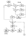
- Figs. 3A-3D are flow charts of the programs which are executed by the microprocessor in Fig. 2; and
- Fig. 4 is a memory map which illustrates the data structures employed by the programs of Fig. 3.
- Referring particularly to Fig. 1, the
tag 1 of the present invention includes acircuit board 2 which is enclosed in a moldedplastic housing 3. Thehousing 3 is attached to a flexible strap orbelt 4 which may be attached around an appendage on the animal being monitored. In the case of dairy cows, thestrap 4 is designed to attach securely to the hind leg of the cow. The interior of thehousing 3 is completely filled with a potting compound to retain thecircuit 2 and the electrical components. - Referring particularly to Fig. 2, the circuitry on the
circuit board 2 is structured about an 8-bit microprocessor 5 which is driven by a 32.768 kHz clock circuit 6. Power is provided to themicroprocessor 5 and the remaining circuit elements by a 1.7 ampere-hour lithium battery 7 which provides 3.7 volts at a terminal VDD. Themodel MC146805E2 microprocessor 5 is employed and it is manufactured using CMOS technology. It draws very little current and in addition, themicroprocessor 5 may be placed into a "wait" state in which it draws approximately 40 microwatts of power. This feature is employed in the preferred embodiment to obtain a battery life of from three to four years. - Referring particularly to Figs. 1 and 2, the
microprocessor 5 has an 8-bit 1/0 port B which can be configured to input or output data under program control. Four leads of this B port (PBO-PB3) are configured as outputs and are connected to respective driver transisitors 8-12. The transistors 8-12 provide amplification which enables the outputs PBO-PB3 to energize respective light emitting diodes (LED) 13-16. The LEDs 13-16 extend through thehousing 3 where they may be easily seen and provide a visual indication of the extent of the animal's activity. The LED 13 provides a means for outputting more extensive data as will be described in more detail below. - The leads PB4-PB7 of the B port are configured to input data to the
microprocessor 5 during production and testing of thetag 1. Lead PB4 is driven low by an external source to place the system in a "test" mode and lead PB5 is driven low by an external source when data is to be entered into the microprocessor. The serial data string is applied to lead PB7 and themicroprocessor 5 is programmed to read this input data each time a negative voltage transition occurs in a clock signal which is applied to input lead PB6. - Referring particularly to Fig. 2, the
microprocessor 5 is reset each time its reset terminal (R) is pulled to a logic low voltage. This is accomplished by a normallyopen reed switch 17 which connects to circuit ground. When a magnet is brought near thetag 1, its magnetic field closes the contacts in thereed switch 17 to perform the reset function. It is contemplated that the user will perform this reset function whenever one of the LEDs 14-16 is energized. As will be explained in more detail below, when a reset occurs themicroprocessor 5 is vectored to a reset program which is executed to initialize the system and to perform a number of other functions. - The activity of the animal to which the
tag 1 is attached is detected by amercury switch 18. One lead of theswitch 18 is connected to circuit ground and the other lead connects to the clock input of a D-type flip-flop 19. The flip-flop 19 has its D input connected to a logic high voltage and it operates as a latch which generates a logic low voltage at itsoutput each time the
mercury switch 18 closes. Thelatch 19 connects to an IRLinterrupt lead on themicroprocessor 5 and with each mercury switch closure, themicroprocessor 5 is vectored to an IRQ interrupt program. As shown in Fig. 3D and 4, the IRinterrupt program contains instructions indicated by process block 20 which increment an
activity number counter 21. In addition, instructions indicated byprocess block 22 are executed to reset thelatch 19 through the microprocessor's output port PA7. - Referring again to Fig. 2, the
microprocessor 5 contains sufficient on-chip memory to store data for normal applications of thetag 1. However, it is contemplated that the tag 1 will also be used in experimental programs in which the activity of the animal may be recorded over extended periods of time. Accordingly, provision is made for the addition of an external random access memory (RAM) 23 which may store additional activity data. A 2Kx8 CMOS RAM manufactured by Hitachi as the HM6116LP-4 is employed in the preferred embodiment. TheRAM 23 is connected to an 8-bit data bus 24 which is driven by a bidirectional, multiplexed address/data port (leads BO-B7) on themicroprocessor 5. These.same leads BO-B7 serve to generate the lower eight bits of an address when a microprocessor address strobe terminal (AS) is at a logic high voltage and this address data is stored in alatch 25 for application to theRAM 23. The three most significant address bits are generated at microprocessor address leads (A8-A10) which are connected directly to theRAM 23 by bus 26. TheRAM 23 is enabled by aNAND gate 27 when a data strobe lead (DS) on themicroprocessor 5 goes high and data is then written to an addressed RAM location when a microprocessor read/write lead (R/W) goes to a logic low voltage. Data is read from an addressed location in theRAM 23 when the R/W lead goes high and aninverter gate 28 drives the output enable lead (OE) on theRAM 23 to a logic low voltage. - The
microprocessor 5 executes stored program instructions to perform a number of functions. The assembly language listings of these stored programs are provided in Appendix A and flow charts of these programs are illustrated in Figs. 3A-3D. As indicated above, two versions of the tag 1 are contemplated. The first version is for normal applications in which an animal activity profile over a sixty hour period is stored in the tag and employed to detect estrus. When estrus is detected, one of the LED indicators 14-16 is energized. The second version of the tag is for experimental use. This second version stores a much longer animal activity profile and it provides a number of communicating features which will be described in more detail below. In the following description, the second version of the tag is illustrated and asterisks denote those portions of the programs which may be deleted to form the first version of the tag. - Referring particularly to Figs. 3A and 4, each time a magnet is brought near the
tag 1, theread switch 17 is closed and a reset program is executed. As indicated byprocess block 30, this program initializes the microprocessor's A and B ports, as well as a pointer to an activity table 31. The status of microprocessor input lead PB5 is then tested, as indicated bydecision block 33, to determine if data is to be input into the system. If so, a loop which includesdecision block 34 andprocess block 35 is entered and data is input through microprocessor input lead PB7 and stored in its internal RAM. Such data is entered during manufacture of the tag and may include a serial number and date which uniquely identifies the tag, as well as key parameters which customize the tag to the particular animals being monitored. Under normal operating conditions, however, the reset program branches atdecision block 33 and no input data is received. - Referring still to Fig. 3A, the reset program outputs the animal's activity profile data from the activity table 31, as indicated by process block 36. This is accomplished by writing the data serially to the output lead PBO which drives the LED 13. The LED 13 is thus energized to indicate a logic "0" and is de-energized to indicate a logic "I". An instrument (not shown in the drawings) may be coupled to the
tag 1 to read this serial data which is output through the LED 13. In addition to the activity table data, other data such as diagnostic information may be output, or as indicated byprocess block 37, the much larger animal activity profile stored in the data base table 32 may also be output. In any case, each of the LEDs 13-16 is then momentarily energized as indicated byprocess block 38 to insure that they work properly and further initialization is performed as indicated atprocess block 39. A "rate number" 40 is then reset to zero as indicated atprocess block 41 and a WAIT instruction is then executed to place themicroprocessor 5 in its low-power wait state. In this wait state the microprocessor's internal timer continues to operate and themicroprocessor 5 is responsive to the IRQinterrupt, timer interrupt and a reset interrupt. After a timer interrupt or an IRinterrupt is serviced, however, the system returns at 42 and is again placed in the low-power wait state.
- As indicated above, the IRinterrupt occurs each time the

mercury switch 18 closes. The IRinterrupt service routine (Fig. 3D) merely increments the
activity number counter 21 and resets thelatch 19 before returning to the wait state. This event occurs each time the animal moves sufficiently to bring the mercury bead in theswitch 18 into contact with its internal leads. The number of such movements are accumulated in the two-byte activity counter 21. - Referring to Fig. 3B, the internal timer in the
microprocessor 5 is initialized to generate a timer interrupt every 2.5 seconds. As indicated by decision blocks 45-47, when this interrupt occurs, the system is vectored to the timer interrupt service routine which examines the current value of the rate number 40. As will become apparent from the description below, the rate number is indicative of the activity of the animal over a recent time period as compared to the activity of the animal over a longer reference period. When the rate number is less than two, as determined atdecision block 45, the animal's current activity is not noteworthy. Otherwise, one of the LEDs 14-16 is energized, as indicated by process blocks 49-51, to provide a visual indication that noteworthy activity is occurring. The appropriate LED is energized for 50 milliseconds, as indicated by process blocks 53 and 54 but because the timer interrupt occurs every 2.5 seconds, the energized LED blinks continuously. Only one of the LEDs 14-16 is energized at any time and by observing which LED is illuminated, the relative increase in animal activity can be easily determined. Although the absolute activity which indicates estrus will vary from animal to animal, it has been found that a significant relative increase in animal activity is an accurate indication of estrus. - Every hour the rate number is recalculated to provide an updated indication of animal activity. Referring particularly to Figs. 3B and 3C, the state of input lead PB4 is tested at
decision block 56 to determine if the tag is undergoing testing. If not, atime counter 57 is incre- ented as indicated atprocess block 58 and the value of thiscounter 57 is then checked to determine if an hour has elapsed. If not, the system branches at decision block 59, the internal timer is reset at process block 60 and the system returns to the wait mode for another 2.5 seconds. If a one hour "sample" period has elapsed, the time counter 157 is reset atprocess block 61 and a new rate number is calculated. It should be apparent that the test mode of operation merely bypasses the one hour time requirement for recalculation of the rate number and this feature merely enables the tag to be quickly tested. - Referring particularly to Fig. 3C, before calculating a new rate number, the animal activity profiles are updated with the most current activity number. As indicated by
process block 62, the contents of theactivity counter 21 is first stored in the activity data base table 32. The same number is then divided by sixteen, as indicated byprocess block 63 to form a single byte result which is stored atprocess block 64 in the activity table 31. Theactivity counter 21 is then reset to zero atprocess block 65 to begin accumulating activity counts for the next hour. - As indicated at process block 66, the activity counts for the twelve most recent hours are then read from the activity table 31 and added together to provide a current activity value which is stored at "SUM". The value of the forty-eight least recent activity numbers are then read from the activity table 31 at
process block 67 and added together to form a reference activity number which is stored at "TOTAL". The ratio of the current activity to the reference activity is then calculated at process block 68 to form the current rate number. If the calculated current rate is greater than the value stored as the rate number 40, the system branches atdecision block 69 and updates the rate number 40 at process block 70. In either case, the internal timer is then reset atprocess block 71 and the system returns to the wait mode for another 2.5 seconds. - In the preferred embodiment, the reference activity is calculated over a forty-eight hour period and the current activity is calculated over the most recent twelve hour period. These time periods can, of course, be easily changed to accommodate the activity patterns of various animals and breeds. Indeed, one of the purposes of the data base table option in the
tag 1 is to store activity data over a much longer time period. This activity profile data can then be read out as described above and studied to determine the optimal values of the "reference" and "current" time periods. The optimal values of these key parameters may be entered into the production tags which are to be employed on that particular animal breed. Although the use of a microprocessor offers many advantages, it is also possible to construct a circuit which will emulate the functions described above. This and many other variations from the preferred embodiment described herein are possible without departing from the spirit of the invention.

- Routine which stores a sixteen bit activity count in the activity data base area of RAM (100H to 5FFH) Required for research model only.


- File pointer initialization may be required for initial Power ON condition
-

- Routine used to store tag serial number and manufacturing date in RAM
-
Port B bit 5 = 0, routine is enabled - Port B bit 6 = HIGH to LOW transition, shift bit into RAM
-
Port B bit 7, data bit to be shifted into RAM

- Memory dump routine - locations OOH to FFH


- Routine for servicing a Timer interrupt


- Routine for servicing an External interrupt (activity switch closure)

- Serial
data transmission routine 1 start bit, 8 bits of data, no parity, 2 or more stop bits
- Routine which dumps the contents of memory locations 100H to 5FFH. Required for research model tag only.


- Establish interrupt vector table


Claims (11)
Applications Claiming Priority (2)
| Application Number | Priority Date | Filing Date | Title |
|---|---|---|---|
| US345580 | 1982-02-04 | ||
| US06/345,580 US4455610A (en) | 1982-02-04 | 1982-02-04 | Self-contained estrous detection tag |
Publications (3)
| Publication Number | Publication Date |
|---|---|
| EP0087015A2 true EP0087015A2 (en) | 1983-08-31 |
| EP0087015A3 EP0087015A3 (en) | 1983-12-07 |
| EP0087015B1 EP0087015B1 (en) | 1986-11-12 |
Family
ID=23355609
Family Applications (1)
| Application Number | Title | Priority Date | Filing Date |
|---|---|---|---|
| EP83100945A Expired EP0087015B1 (en) | 1982-02-04 | 1983-02-01 | Self-contained estrus detection tag |
Country Status (6)
| Country | Link |
|---|---|
| US (1) | US4455610A (en) |
| EP (1) | EP0087015B1 (en) |
| AU (1) | AU564595B2 (en) |
| CA (1) | CA1187579A (en) |
| DE (1) | DE3367512D1 (en) |
| NZ (1) | NZ203165A (en) |
Cited By (7)
| Publication number | Priority date | Publication date | Assignee | Title |
|---|---|---|---|---|
| WO1986004802A1 (en) * | 1985-02-26 | 1986-08-28 | Lucien Steru | Method and device for evaluating the psychotropic effects of medicinal substances on animals |
| EP0263629A2 (en) * | 1986-10-10 | 1988-04-13 | Cowtronics, Inc. | Method and apparatus for detecting standing heat in cattle |
| FR2645641A1 (en) * | 1989-04-10 | 1990-10-12 | Bruno Comby | METHOD AND DEVICE FOR MEASURING VIBRATIONS, IN PARTICULAR MICROSCOPIC TREMBLING OF LIVING ORGANISMS |
| WO1991011678A2 (en) * | 1990-01-29 | 1991-08-08 | N.V. Nederlandsche Apparatenfabriek Nedap | A method of, and apparatus for, measuring movements |
| EP0549081A1 (en) * | 1991-12-24 | 1993-06-30 | Stichting Instituut Voor Mechanisatie Arbeid En Gebouwen | Device for measuring the activity of an animal |
| EP0705536A1 (en) | 1994-10-03 | 1996-04-10 | N.V. Nederlandsche Apparatenfabriek NEDAP | Activity detector with position-dependent movement sensor |
| FR3039361A1 (en) * | 2015-07-27 | 2017-02-03 | Reyflex | IDENTIFICATION RING WITH DETECTOR OF A HEAT STATE OF AN ANIMAL. |
Families Citing this family (19)
| Publication number | Priority date | Publication date | Assignee | Title |
|---|---|---|---|---|
| US4502487A (en) * | 1983-04-29 | 1985-03-05 | Dubrucq Denyse C | Optical thermodetector |
| US4635587A (en) * | 1985-06-06 | 1987-01-13 | Cowtronics, Inc. | Method and apparatus for detecting standing heat in cattle |
| US5111799A (en) * | 1990-03-28 | 1992-05-12 | Washington State University Research Foundation, Inc. | Estrous detection systems |
| SE504267C2 (en) * | 1994-06-01 | 1996-12-16 | Tetra Laval Holdings & Finance | Identity and cobstone indicator |
| SE9504707L (en) * | 1995-12-29 | 1997-06-30 | Alfa Laval Agri Ab | activity Measurement |
| US5881673A (en) * | 1997-09-25 | 1999-03-16 | Beach; Mark | Heat detection system |
| US7083575B1 (en) * | 1998-12-22 | 2006-08-01 | Cowchips, Llc | Electronic estrus detection device |
| MXPA01006237A (en) * | 1998-12-22 | 2002-04-17 | Ddx Inc | Electronic estrus detection device. |
| US6577241B2 (en) * | 2001-09-25 | 2003-06-10 | Van H. Neidig | Method for centralized animal identification and tracking |
| WO2005010665A2 (en) | 2003-07-17 | 2005-02-03 | Jackson William R Iii | Method and apparatus for monitoring breeding behavior |
| ITMI20071072A1 (en) * | 2007-05-25 | 2008-11-26 | Lps Electronics S R L | EQUIPMENT FOR THE AUTOMATIC DETECTION OF THE HEAT OF A SHROUD. |
| US7137359B1 (en) | 2005-11-08 | 2006-11-21 | Braden Joe T | Estrus detector |
| EP1839621A1 (en) * | 2006-03-31 | 2007-10-03 | Walter Signorini | Method and system to determine a physiological state of a sow |
| US8551012B2 (en) * | 2007-05-25 | 2013-10-08 | Walter Signorini | Method for monitoring estrus and ovulation of animals, and for planning a useful fertilization time zone and a preferred fertilization time zone |
| DE102014003846B4 (en) | 2014-03-18 | 2016-09-08 | Leibniz-Institut Für Nutztierbiologie | Device for recording animal-specific behavioral parameters of animals |
| US10278675B2 (en) * | 2014-07-31 | 2019-05-07 | Palo Alto Research Center Incorporated | Implantable estrus detection devices, systems, and methods |
| US9992977B2 (en) * | 2015-06-03 | 2018-06-12 | Keltronix, Inc. | Agricultural monitoring system using image analysis |
| US11617352B2 (en) | 2018-01-23 | 2023-04-04 | William R. Jackson, III | Method and apparatus for detection of estrus and optimal time for embryo transfer or artificial insemination in animals |
| US11355005B2 (en) * | 2019-07-22 | 2022-06-07 | Battelle Memorial Institute | Aquatic organism tracking devices, systems and associated methods |
Citations (6)
| Publication number | Priority date | Publication date | Assignee | Title |
|---|---|---|---|---|
| DE2316130A1 (en) * | 1973-03-30 | 1974-10-10 | Siemens Ag | DEVICE FOR DETECTING MOVEMENTS OF A BODY |
| US3844273A (en) * | 1972-04-24 | 1974-10-29 | Contel Corp | Method and apparatus for animal heat detection and recording |
| US4117834A (en) * | 1976-12-02 | 1978-10-03 | Mc Partland Richard J | Physiological motor activity monitoring apparatus |
| GB2058359A (en) * | 1979-08-28 | 1981-04-08 | Derksen J C | Activity measurement apparatus for animals |
| GB2076259A (en) * | 1980-05-13 | 1981-11-25 | Rodrian James A | Animal identification and estrus detection system |
| US4353375A (en) * | 1977-04-26 | 1982-10-12 | The United States Of America As Represented By The Department Of Health & Human Services | Activity monitor for ambulatory subjects |
Family Cites Families (5)
| Publication number | Priority date | Publication date | Assignee | Title |
|---|---|---|---|---|
| US4151831A (en) * | 1976-11-15 | 1979-05-01 | Safetime Monitors, Inc. | Fertility indicator |
| US4112926A (en) * | 1976-12-08 | 1978-09-12 | The Children's Memorial Hospital | Method and apparatus for measuring and treating hyperactivity in human beings |
| US4192000A (en) * | 1977-07-14 | 1980-03-04 | Calorie Counter Limited Partnership | Electronic calorie counter |
| CH626224B (en) * | 1978-08-09 | 1900-01-01 | Bioself Int Inc | POCKET CALCULATOR FOR THE PREDICTION OF TIME CYCLES. |
| US4247758A (en) * | 1979-11-15 | 1981-01-27 | Rodrian James A | Animal identification and estrus detection system |
-
1982
- 1982-02-04 US US06/345,580 patent/US4455610A/en not_active Expired - Lifetime
-
1983
- 1983-01-31 CA CA000420581A patent/CA1187579A/en not_active Expired
- 1983-02-01 DE DE8383100945T patent/DE3367512D1/en not_active Expired
- 1983-02-01 EP EP83100945A patent/EP0087015B1/en not_active Expired
- 1983-02-02 AU AU10930/83A patent/AU564595B2/en not_active Ceased
- 1983-02-02 NZ NZ203165A patent/NZ203165A/en unknown
Patent Citations (6)
| Publication number | Priority date | Publication date | Assignee | Title |
|---|---|---|---|---|
| US3844273A (en) * | 1972-04-24 | 1974-10-29 | Contel Corp | Method and apparatus for animal heat detection and recording |
| DE2316130A1 (en) * | 1973-03-30 | 1974-10-10 | Siemens Ag | DEVICE FOR DETECTING MOVEMENTS OF A BODY |
| US4117834A (en) * | 1976-12-02 | 1978-10-03 | Mc Partland Richard J | Physiological motor activity monitoring apparatus |
| US4353375A (en) * | 1977-04-26 | 1982-10-12 | The United States Of America As Represented By The Department Of Health & Human Services | Activity monitor for ambulatory subjects |
| GB2058359A (en) * | 1979-08-28 | 1981-04-08 | Derksen J C | Activity measurement apparatus for animals |
| GB2076259A (en) * | 1980-05-13 | 1981-11-25 | Rodrian James A | Animal identification and estrus detection system |
Non-Patent Citations (1)
| Title |
|---|
| JOURNAL OF DAIRY SCIENCE, vol. 60, no. 2, February 1977, pages 235-243, Champaign, Illinois, USA; C.A. KIDDY: "Variation in physical activity as an indication of estrus in dairy cows". * |
Cited By (13)
| Publication number | Priority date | Publication date | Assignee | Title |
|---|---|---|---|---|
| WO1986004802A1 (en) * | 1985-02-26 | 1986-08-28 | Lucien Steru | Method and device for evaluating the psychotropic effects of medicinal substances on animals |
| FR2577791A1 (en) * | 1985-02-26 | 1986-08-29 | Steru Lucien | METHOD AND DEVICE FOR EVALUATING THE PSYCHOTROPIC EFFECTS OF MEDICINAL SUBSTANCES IN ANIMALS |
| EP0263629A2 (en) * | 1986-10-10 | 1988-04-13 | Cowtronics, Inc. | Method and apparatus for detecting standing heat in cattle |
| EP0263629A3 (en) * | 1986-10-10 | 1989-03-29 | Cowtronics, Inc. | Method and apparatus for detecting standing heat in cattle |
| US5265619A (en) * | 1989-04-10 | 1993-11-30 | Bruno Comby | Process and device for measuring vibrations, in particular nervous trembling in living organisms |
| WO1990012293A1 (en) * | 1989-04-10 | 1990-10-18 | Bruno Comby | Process and device for measuring vibrations, in particular nervous trembling in living organisms |
| FR2645641A1 (en) * | 1989-04-10 | 1990-10-12 | Bruno Comby | METHOD AND DEVICE FOR MEASURING VIBRATIONS, IN PARTICULAR MICROSCOPIC TREMBLING OF LIVING ORGANISMS |
| WO1991011678A2 (en) * | 1990-01-29 | 1991-08-08 | N.V. Nederlandsche Apparatenfabriek Nedap | A method of, and apparatus for, measuring movements |
| WO1991011678A3 (en) * | 1990-01-29 | 1991-10-17 | Nedap Nv | A method of, and apparatus for, measuring movements |
| EP0549081A1 (en) * | 1991-12-24 | 1993-06-30 | Stichting Instituut Voor Mechanisatie Arbeid En Gebouwen | Device for measuring the activity of an animal |
| EP0705536A1 (en) | 1994-10-03 | 1996-04-10 | N.V. Nederlandsche Apparatenfabriek NEDAP | Activity detector with position-dependent movement sensor |
| NL9401617A (en) * | 1994-10-03 | 1996-05-01 | Nedap Nv | Activity detector with position-dependent motion sensor. |
| FR3039361A1 (en) * | 2015-07-27 | 2017-02-03 | Reyflex | IDENTIFICATION RING WITH DETECTOR OF A HEAT STATE OF AN ANIMAL. |
Also Published As
| Publication number | Publication date |
|---|---|
| AU564595B2 (en) | 1987-08-20 |
| EP0087015B1 (en) | 1986-11-12 |
| NZ203165A (en) | 1985-01-31 |
| EP0087015A3 (en) | 1983-12-07 |
| CA1187579A (en) | 1985-05-21 |
| AU1093083A (en) | 1983-08-11 |
| US4455610A (en) | 1984-06-19 |
| DE3367512D1 (en) | 1987-01-02 |
Similar Documents
| Publication | Publication Date | Title |
|---|---|---|
| EP0087015B1 (en) | Self-contained estrus detection tag | |
| US4895165A (en) | Electronic estrus detector | |
| US6059733A (en) | Method of determining a physiological state of a ruminant animal using an ingestible bolus | |
| AU717436B2 (en) | Activity measurement | |
| US4635587A (en) | Method and apparatus for detecting standing heat in cattle | |
| US6860859B2 (en) | Apparatus and method for detection of estrus and/or non-pregnancy | |
| US6758006B1 (en) | Fishing information device and method of using same | |
| US4846106A (en) | Method and apparatus for detecting standing heat in cattle | |
| US6049280A (en) | Identity and cow estrus indicator | |
| US5322034A (en) | Livestock record system | |
| US7083575B1 (en) | Electronic estrus detection device | |
| WO1991014402A1 (en) | Estrous detection systems | |
| EP2599384A1 (en) | Estrus detection device and estrus detection system | |
| CA2122521C (en) | Monitoring gaseous oxygen concentration | |
| US4168494A (en) | Livestock confinement structure monitor | |
| JPH07506188A (en) | Data logger | |
| AU772912B2 (en) | Determining meat quality of a live animal | |
| US7230535B2 (en) | Method and apparatus for monitoring breeding behavior | |
| US5469739A (en) | On-line fishing depth indicator with encapsulated components | |
| EP0749687A1 (en) | A fish-bite indicator | |
| US4165033A (en) | Identification system | |
| MXPA01006237A (en) | Electronic estrus detection device. | |
| CA1130391A (en) | Device for indicate oestrus and/or illness in cows | |
| JP2001120097A (en) | Management apparatus for motion quantity of animal | |
| EP0232263A1 (en) | Monitor for liquid level and urine flow |
Legal Events
| Date | Code | Title | Description |
|---|---|---|---|
| PUAI | Public reference made under article 153(3) epc to a published international application that has entered the european phase |
Free format text: ORIGINAL CODE: 0009012 |
|
| AK | Designated contracting states |
Designated state(s): DE FR GB IT NL |
|
| PUAL | Search report despatched |
Free format text: ORIGINAL CODE: 0009013 |
|
| AK | Designated contracting states |
Designated state(s): DE FR GB IT NL |
|
| 17P | Request for examination filed |
Effective date: 19840201 |
|
| GRAA | (expected) grant |
Free format text: ORIGINAL CODE: 0009210 |
|
| AK | Designated contracting states |
Kind code of ref document: B1 Designated state(s): DE FR GB IT NL |
|
| REF | Corresponds to: |
Ref document number: 3367512 Country of ref document: DE Date of ref document: 19870102 |
|
| ET | Fr: translation filed | ||
| ITF | It: translation for a ep patent filed |
Owner name: DE DOMINICIS & MAYER S.R.L. |
|
| PLBE | No opposition filed within time limit |
Free format text: ORIGINAL CODE: 0009261 |
|
| STAA | Information on the status of an ep patent application or granted ep patent |
Free format text: STATUS: NO OPPOSITION FILED WITHIN TIME LIMIT |
|
| 26N | No opposition filed | ||
| ITTA | It: last paid annual fee | ||
| PGFP | Annual fee paid to national office [announced via postgrant information from national office to epo] |
Ref country code: DE Payment date: 20010122 Year of fee payment: 19 |
|
| PGFP | Annual fee paid to national office [announced via postgrant information from national office to epo] |
Ref country code: GB Payment date: 20010131 Year of fee payment: 19 |
|
| PGFP | Annual fee paid to national office [announced via postgrant information from national office to epo] |
Ref country code: FR Payment date: 20010213 Year of fee payment: 19 |
|
| PGFP | Annual fee paid to national office [announced via postgrant information from national office to epo] |
Ref country code: NL Payment date: 20010228 Year of fee payment: 19 |
|
| REG | Reference to a national code |
Ref country code: GB Ref legal event code: IF02 |
|
| PG25 | Lapsed in a contracting state [announced via postgrant information from national office to epo] |
Ref country code: GB Free format text: LAPSE BECAUSE OF NON-PAYMENT OF DUE FEES Effective date: 20020201 |
|
| PG25 | Lapsed in a contracting state [announced via postgrant information from national office to epo] |
Ref country code: NL Free format text: LAPSE BECAUSE OF NON-PAYMENT OF DUE FEES Effective date: 20020901 |
|
| PG25 | Lapsed in a contracting state [announced via postgrant information from national office to epo] |
Ref country code: DE Free format text: LAPSE BECAUSE OF NON-PAYMENT OF DUE FEES Effective date: 20020903 |
|
| GBPC | Gb: european patent ceased through non-payment of renewal fee |
Effective date: 20020201 |
|
| PG25 | Lapsed in a contracting state [announced via postgrant information from national office to epo] |
Ref country code: FR Free format text: LAPSE BECAUSE OF NON-PAYMENT OF DUE FEES Effective date: 20021031 |
|
| NLV4 | Nl: lapsed or anulled due to non-payment of the annual fee |
Effective date: 20020901 |
|
| REG | Reference to a national code |
Ref country code: FR Ref legal event code: ST |