EP0089850A1 - Improvements in cab construction for industrial vehicles - Google Patents
Improvements in cab construction for industrial vehicles Download PDFInfo
- Publication number
- EP0089850A1 EP0089850A1 EP83301571A EP83301571A EP0089850A1 EP 0089850 A1 EP0089850 A1 EP 0089850A1 EP 83301571 A EP83301571 A EP 83301571A EP 83301571 A EP83301571 A EP 83301571A EP 0089850 A1 EP0089850 A1 EP 0089850A1
- Authority
- EP
- European Patent Office
- Prior art keywords
- cab
- air
- window
- plenum chamber
- interior
- Prior art date
- Legal status (The legal status is an assumption and is not a legal conclusion. Google has not performed a legal analysis and makes no representation as to the accuracy of the status listed.)
- Withdrawn
Links
Images


Classifications
-
- B—PERFORMING OPERATIONS; TRANSPORTING
- B60—VEHICLES IN GENERAL
- B60H—ARRANGEMENTS OF HEATING, COOLING, VENTILATING OR OTHER AIR-TREATING DEVICES SPECIALLY ADAPTED FOR PASSENGER OR GOODS SPACES OF VEHICLES
- B60H1/00—Heating, cooling or ventilating [HVAC] devices
- B60H1/24—Devices purely for ventilating or where the heating or cooling is irrelevant
- B60H1/241—Devices purely for ventilating or where the heating or cooling is irrelevant characterised by the location of ventilation devices in the vehicle
- B60H1/245—Devices purely for ventilating or where the heating or cooling is irrelevant characterised by the location of ventilation devices in the vehicle located in the roof
-
- B—PERFORMING OPERATIONS; TRANSPORTING
- B60—VEHICLES IN GENERAL
- B60H—ARRANGEMENTS OF HEATING, COOLING, VENTILATING OR OTHER AIR-TREATING DEVICES SPECIALLY ADAPTED FOR PASSENGER OR GOODS SPACES OF VEHICLES
- B60H1/00—Heating, cooling or ventilating [HVAC] devices
- B60H1/00357—Air-conditioning arrangements specially adapted for particular vehicles
- B60H1/00378—Air-conditioning arrangements specially adapted for particular vehicles for tractor or load vehicle cabins
-
- B—PERFORMING OPERATIONS; TRANSPORTING
- B62—LAND VEHICLES FOR TRAVELLING OTHERWISE THAN ON RAILS
- B62D—MOTOR VEHICLES; TRAILERS
- B62D33/00—Superstructures for load-carrying vehicles
- B62D33/06—Drivers' cabs
- B62D33/0617—Drivers' cabs for tractors or off-the-road vehicles
Landscapes
- Engineering & Computer Science (AREA)
- Mechanical Engineering (AREA)
- Physics & Mathematics (AREA)
- Thermal Sciences (AREA)
- Chemical & Material Sciences (AREA)
- Combustion & Propulsion (AREA)
- Transportation (AREA)
- Body Structure For Vehicles (AREA)
Abstract
A method of heating cabs (11) of industrial vehicles used in cold environments in which heated air is driven through at least one window space (73) defined between a pair (60, 66) of generally parallel spaced transparent window panes before entering the cab. Also an industrial vehicle for use in cold environments comprising a cab with windows on at least three sides, an air inlet (41, 44, 82), and an air outlet (82), the windows having generally parallel spaced inner (66) and outer panes (60) with the interior space (73) vented to the interior of the cab, and means (48) for forcing heated air through the window spaces (73) between the inner (66) and outer panes (60) before entering the cab.
Description
- This invention relates to improvements in cab construction for industrial vehicles. By "industrial vehicles" it is intended to include all such vehicles containing a cab in which an operator or driver must sit for long periods, often in inclement environmental conditions. Particular instances are heavy load vehicles and construction vehicles which often operate at sub-zero temperatures. However the invention applies in particular to industrial trucks, e.g. reach trucks. One aspect of the invention involves a heating system for the cabs of industrial vehicles operating at low temperatures. In the case of industrial trucks this is particularly applicable to such trucks, particularly reach trucks, adapted to operate within refrigerated warehouses.
- The demisting of windows of cabs of industrial vehicles is especially difficult under very cold e.g. sub-zero conditions. The normal method of projecting heated air against the interior surface of the windscreen or window is unsatisfactory in that if the air is heated to a sufficiently high temperature for demisting purposes, the cab becomes overheated for the driver. Proposals have been made for using different forms of double glazing. The use of sealed units is very expensive and places constraints upon cab design and in particular upon clear vision in all directions. It has been proposed, see e.g.
British Patent 1 103 480 to inject heated air between spaced panes of glass at the windscreen but the imposition of a closed circuit within the windscreen leads to considerable construction difficulties and would not solve the problem of all round vision which is so necessary for safety especially in industrial trucks. Furthermore separate heating systems are necessary for the cab interior and the windscreen. - It has also been proposed in
British Patent 1 121 048 to demist the rear windscreen of a motor car by extracting the heated interior air between parallel panes of glass. However such a system could not be used for industrial vehicle cabs in very cold weather since the cab interior would have to be heated to an intolerable temperature for demisting to operate effectively. - According to one aspect of the invention there is provided a method of heating cabs of industrial vehicles used in cold environments characterised in that air heated to a temperature sufficient for demisting purposes is maintained under an over-pressure within a plenum chamber extending over the cab roof and is distributed to window spaces on three sides of the cab, each window space being defined between a pair of generally parallel spaced transparent window panes, the window spaces communicating at their upper ends with the plenum chamber and at their lower ends with the cab interior. The heated air may enter the cab interior under the lower edges of the inner panes.
- The air may be partly drawn in from the cab interior and partly drawn in from a heated region of the motor compartment and heated to a controlled temperature before being re-introduced through the window spaces, a part of the cab interior air being continually expelled.
- The air may be drawn upwardly into the plenum chamber through a window not served by the air leaving the plenum chamber. In, for example, industrial trucks, the window may be within the door.
- Preferably an over-pressure is produced in the plenum chamber. This serves to ensure that the air is sufficiently distributed through all of the window spaces. A slight residual over-pressure may remain within the cab ensuring that some of the air is continually expelled and replenished.
- The invention includes an industrial vehicle for use in cold environments comprising a cab with windows on at least three sides, an air inlet, and an air outlet, the windows having generally parallel spaced inner and outer panes with the interior space vented to the interior of the cab, and means for forcing heated air through the window spaces between the inner and outer panes before entering the cab.
- In e.g. an industrial truck the roof will normally be transparent and it may comprise inner and outer panes defining the plenum chamber.
- A fan in the roof preferably has an outlet communicating with the plenum chamber and arranged to maintain the aforementioned over-pressure. The fan may be at the rear of the plenum chamber and have an inlet communicating with an air inlet passage in the cab door, which may itself comprise spaced transparent panels between which passes the inlet air to the fan. A heating element may be located within the door at the entry to the door window space. Preferably at least one heating element is located at the fan outlet and more preferably there are provided a plurality of individually controlled heating elements so that the temperature of the air can be satisfactorily controlled.
- In an industrial truck the non-recirculated air is conveniently drawn from the motor compartment which is often under the driver's seat.
- The window panes e.g. outer window panes serving three sides may be formed as a demountable unit. This is particularly important where the heating system described above is employed since access for cleaning the interior surfaces of the panes is thereby conveniently provided. In addition, the concept facilitates servicing of components, access to which is within the cab. In industrial trucks in particular, servicing can be a problem due to the compactness of the design generally which means that access is necessary from as many directions as possible. The demountable unit also provides a very convenient safety measure, allowing ready escape of a driver in the event of an accident.
- The demountable unit comprises or consists of a moulding of structural transparent plastics material defining windows for the three sides and connected between the roof structure and a U-shaped lintel. This moulding may be demountable independently from the remaining cab structure.
- Where an inner window pane construction is used, this may be defined by an inner moulding of structural transparent plastics material spaced from the first mentioned moulding and having three sides and a roof.
- There may be an upper transparent panel of structural transparent plastics material defining with the inner moulding a hollow roof space communicating with the space between the inner and outer transparent mouldings defining the windows.
- In all cases the plastics material is preferably of polycarbonate e.g. of 6 mm thickness.
- Preferably, the cab comprises a structural frame for the windows, roof and door which is constructed as a structurally independent removable unit.
- The unit may comprise a rear frame extending from the roof to the door step and defining with the door a rear wall having at its lower end a weight-supporting base resting on and bolted to a weight-supporting element on the chassis.
- The unit may comprise extending from the rear frame, a generally U-shaped lintel at the base of the windows at the three remaining sides of the cab, the lintel having on its two projecting limbs a weight-supporting abutment resting on and secured to weight-supporting elements on the chassis.
- An embodiment illustrating the invention is hereafter described with reference to the accompanying drawings, in which:-
- Figures 1, 2 and 3 are different perspective views of a reach truck incorporating the invention;
- Figure 4 is a side elevational view partly cut away, of the truck of Figure 1;
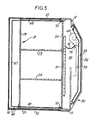
- Figure 5 is a plan view, partly cut away, of the cab of the truck of Figure 1; and
- Figure 6 is a rear elevational view of part of the truck of Figure 1.
- As best seen in Figures 1 to 3 there is shown a reach truck having a
chassis 10 and a structurally independent cab unit 11, which is independently removable from the chassis as a self- supporting structure, the lines of separation being indicated by broken line arrows. - The cab unit 11 comprises a structural frame including angle-
section steel pillars heavy steel plate 14 which forms a doorstep at the rear of the cab, and to asimilar steel plate 16 at the top, over which is formed ahollow structure 17 of welded steel plate which defines a fan compartment. - A safety roof structure 18 (Fig. 5) comprising an outer framework of
welded steel plates intermediate struts pillars - The safety roof structure 18 is supported only from the rear to which it is reinforced by the
welded construction 17. There are no pillars e.g. at the front corners. - At the level of the base of the windows a generally
U-shaped lintel structure 25 is welded so that thelimbs pillars web 28 of the U being under the windscreen. A raisededge 29 is provided around the lintel 25 (extended at 29a overpillars 12, 13) which serves as an outward abutment for the outer window structure to be described. - The
pillars lower plates door 30, hinged at 31 and provided with alatch 32, and of hollow construction, there being an outertransparent window 33 sealingly enclosed within anouter steel wall 34 and aninner pane 35 defining with the pane 33 awindow space 36. Theinner pane 35 is sealingly mounted between anupper wall 37 of the hollow door and theupper wall 38 of a lower plenum chamber 39 (Fig. 4). Thechamber 39 has an outlet opening 40 communicating with thewindow space 36, an inlet opening 41 in itsinner wall 42 and houses anelectric bar heater 43, positioned over theopening 41 and under the opening 40. - The opening 41 communicates with an
opening 44 in the motor compartment defined by thebroken line 45 which is under the driver's seat. A thick resilient heat insulatedpad 46 surrounds theopening 41 and is adhered to the wall of thecompartment 45 so as to abut around the opening 41 when the door is closed and guide air withdrawn from the motor compartment into theplenum chamber 39. - At its upper end of the
window space 36 is vented through anopening 47 into the interior of thefan compartment 17 to the inlet side of acentrifugal fan 48 mounted within thefan compartment 17 with its central circular inlet over anopening 49 in theroof 50 of asub-chamber 51 formed over thedoor roof 37. - Welded
abutment plates limbs abutment plates abutment blocks lintel 25 extend through theabutment blocks floor plate 14 rests upon aheavy gauge plate 56 forming part of the chassis at the rear of the truck and a single centrallysituated bolt 57 is welded to theplate 14 and extends through theplate 56 to which it is secured. Thus the whole of the cab unit 11 may be lifted off the chassis by disconnecting the three bolts at the sides of the lintel and the doorstep. - The exterior window panes at the front and two sides of the cab are formed as a
demountable unit 60, preferably as a single moulding of structural transparent plastics material, preferably 6 mm polycarbonate. This material is extremely impact resistant. It provides the sole support between thelintel 25 and the safety roof structure 18 at the sides and front. The generallyU-sectioned moulding 60 rests at its lower edge on thelintel 25 against the projectingrim 29. Arubber grommet 61 is fitted around all of the edges of the unit. The rear edge sealingly engages with thepillars grommet 61 engages behindremovable side plates - Over the roof frame 18 and under edges of the
curved plates roof window pane 65. - It will be apparent that by disengaging the
plates window pane moulding 60 can be removed as a unit giving immediate axis to the interior of the cab. - Within the interior of the cab is a second integrally moulded
unit 66, preferably of 6 mm polycarbonate sheet, having afront windshield portion 67 andside portions unit 66 is supported at its rear edge by means of grommets andbolts 70. When mounted within the cab it is spaced preferably about 3 cm from theouter window unit 60. - As seen particularly in Figures 1 and 4, the
lower edge 72 of theunit 66 is raised above thelintel 25 by about 10cm and is unsupported so that thewindow space 73 at the front and sides is open to the interior of the cab at thelower edge 72, all the way round. - The
window space 73 is furthermore open to the hollowinterior space 74 at the roof, under thepane 65 whichspace 74 defines an upper plenum chamber. Theplenum chamber 74, which tapers towards the front, is open at its rear to thefan compartment 17, above thefloor 50, so that it is exposed to theoutlet 75 of thefan 48. Abaffle 76, extending part way across thefan outlet 75 assists in distributing the air uniformly through theplenum chamber 74. Generally at the forward edge of thebaffle 76, within thefan chamber 17 are transversely extending upper and lowerelectric bar heaters - In operation, an industrial truck housed within a refridgerated store will normally have a mains energised interior heater switched on during the night. When the driver enters he switches on the heating system fully, so that all three bar heaters will normally be energised and also the fan. At the same time the motor is normally switched on which will begin to provide a source of warm air. The air is sucked in by the fan from the motor compartment through the
door window space 36 into aninlet compartment 51 and expelled by the fan into theplenum chamber 74 past theheaters door window space 36 the air will pass theheater 43. The resulting warm air within theplenum chamber 74 develops an over-pressure and is distributed evenly through thewindow spaces 73, demisting the windows and if necessary defrosting, and enters the cab under theedge 72 of the interiorwindow pane unit 66. It will then commence to warm up the interior of the cab. Part of the air re-enters thedoor window space 36 throughopenings 80, by-passing theheater 43, due to baffle 81 within the hollow door. Further air is continually supplied through theopenings more openings 82 in the exterior side window panes, to ensure a continual fresh supply of air. - It is an important feature of the invention that the air at its highest temperature is first passed into the interior window space 73 (including the plenum chamber 74), ensuring both that the hottest air is used for defrosting and demisting purposes and also that the air is partly cooled before it enters the cab interior. In this way a reasonably warm but not unduly heated environment is provided for the operator while at the same time air at considerably higher temperature has access to the window panes where it is required. Thus a single heating system provides a suitable temperature for the operator and demisting purposes. When the motor has fully warmed up, it may be necessary to shut off certain of the heaters and this may be performed thermostatically if necessary.
- As safety precautions, lines of weakness may be provided in the interior and exterior window unit to enable the driver to break the polycarbonate in an accident situation. However the interior unit has little weight to support and may alternatively be housed so as to be comparatively readily disengaged from a channel support. Likewise, the raised
edge 29 may be provided of minimum clearance to enable a thrust at the centre of the windscreen to bow the polycarbonate sufficiently to disengage the lower edge of the unit. - It will be apparent that while the invention in its various aspects has been described in relation to a reach truck, its features will be useful in other forms of industrial truck and in other forms of industrial vehicle, especially where used in very cold environments.
- To enable the driver to communicate with the exterior, a microphone and amplifier system may be utilised within the cab or a two-way radio communication system, so that the driver in a cold store may communicate with personnel outside the store.
- As an alternative to polycarbonate, a sufficiently strong transparent plastics material could be used. An example is high impact polyvinyl chloride.
Claims (12)
1. A method of heating cabs (11) of industrial vehicles used in cold environments characterised in that air heated to a temperature sufficient for demisting purposes is maintained under an over-pressure within a plenum chamber (74) extending over the cab roof and is distributed to window spaces (73) on three sides of the cab, each window space (73) being defined between a pair of generally parallel spaced transparent window panes (60, 66), the window spaces (73) communicating at their upper ends with the plenum chamber (74) and at their lower ends with the cab interior.
2. A method according to claim 1 in which the heated air enters the cab interior under the lower edges (72) of the inner panes (66, 67, 68).
3. A method according to claim 1 or claim 2 wherein the air is partly drawn in from the cab interior and partly drawn in from a heated region of the motor compartment (45) and heated to a controlled temperature before being re-introduced through the window spaces (73), a part of the cab interior air being continually expelled.
4. A method according to claim 3 characterised in that the air is drawn upwardly into the plenum chamber (74) through a window space (36) not served by the air leaving the plenum chamber (74).
5. An industrial vehicle for use in cold environments comprising a cab (11) with windows on at least three sides, a door, an air inlet (41, 44, 82), and an air outlet (82), characterised by
the windows having generally parallel spaced inner (66) and outer (60) panes,means (43, 77, 78) for heating air to a temperature sufficient for demisting purposes, means (48) for maintaining the heated air under an over-pressure within a plenum chamber (74) extending over the cab roof, the window spaces (73) communicating at their upper ends with the plenum chamber (74) and at their lower ends with the cab interior, the over-pressure in the plenum chamber (74) being sufficient to ensure even distribution of air through all of the window spaces (73).
the windows having generally parallel spaced inner (66) and outer (60) panes,means (43, 77, 78) for heating air to a temperature sufficient for demisting purposes, means (48) for maintaining the heated air under an over-pressure within a plenum chamber (74) extending over the cab roof, the window spaces (73) communicating at their upper ends with the plenum chamber (74) and at their lower ends with the cab interior, the over-pressure in the plenum chamber (74) being sufficient to ensure even distribution of air through all of the window spaces (73).
6. A vehicle according to claim 5 including a compartment (17) housing a fan (48) at the rear of the plenum chamber (74), the compartment (17) having an inlet (49) communicating with an air inlet passage (47) in the cab door (30).
7. A vehicle according to claim 6 including a heating element (43) located within the door (30) at the entry to a window space (36) in the door (30).
8. A vehicle according to any of claims 5 to 7 including one or more heating elements (77, 78) located at the fan outlet.
9. A vehicle according to any of claims 5 to 8 wherein the vehicle is an industrial truck and non-recirculated air is drawn from the motor compartment.
10. A vehicle according to any of claims 5 to 9 wherein the outer window panes serving three sides are formed as a demountable unit (60), the unit comprising a moulding of structural transparent plastics material.
11. A vehicle according to any of claims 5 to 10 wherein the interior panes are formed as an integral moulding (66) of structural transparent plastics material and wherein at least part of the lower edges (72) of the interior panes (67, 68, 69) are free so as to permit the air to enter the cab under the edges (72).
12. A vehicle according to any of claims 5 to 11 wherein the cab comprises a structural frame (12, 13, 14, 16, 18, 25) for the windows (60, 66), roof (62, 63, 64, 65) and door (30) which is constructed as a structurally independent removable unit (11).
Applications Claiming Priority (2)
| Application Number | Priority Date | Filing Date | Title |
|---|---|---|---|
| GB8208077 | 1982-03-19 | ||
| GB08208077A GB2116692B (en) | 1982-03-19 | 1982-03-19 | Improvements in cab construction for industrial vehicles |
Publications (1)
| Publication Number | Publication Date |
|---|---|
| EP0089850A1 true EP0089850A1 (en) | 1983-09-28 |
Family
ID=10529126
Family Applications (1)
| Application Number | Title | Priority Date | Filing Date |
|---|---|---|---|
| EP83301571A Withdrawn EP0089850A1 (en) | 1982-03-19 | 1983-03-21 | Improvements in cab construction for industrial vehicles |
Country Status (2)
| Country | Link |
|---|---|
| EP (1) | EP0089850A1 (en) |
| GB (1) | GB2116692B (en) |
Cited By (4)
| Publication number | Priority date | Publication date | Assignee | Title |
|---|---|---|---|---|
| GB2149729A (en) * | 1983-09-24 | 1985-06-19 | Porsche Ag | An improved vehicle wheel suspension |
| EP1051306A1 (en) * | 1998-12-02 | 2000-11-15 | Martin Sheet Metal, Inc. | Cab enclosure panels |
| DE102005012879A1 (en) * | 2005-03-19 | 2006-10-05 | Jungheinrich Ag | Pushing mast lift truck, has front battery partition wall, base-plate of driver`s seating place forming prefabricated box shaped unit, which is firmly and detachably connected by fast fixing units with fixing sections of frame |
| WO2018068141A1 (en) | 2016-10-12 | 2018-04-19 | Tigercat Industries Inc. | Multi-layer protective window system for non-military heavy equipment and method for fabricating same |
Citations (9)
| Publication number | Priority date | Publication date | Assignee | Title |
|---|---|---|---|---|
| US2720149A (en) * | 1953-09-21 | 1955-10-11 | Groene Willard Le Blond | Automobile air conditioning duct system |
| GB922866A (en) * | 1958-07-01 | 1963-04-03 | Saint Gobain | Improvements in or relating to automobile body construction |
| GB1103480A (en) * | 1965-11-22 | 1968-02-14 | Felix Levy | Method and means for preventing the deposit of vapour condensation and rime on windows and windshields |
| GB1121048A (en) * | 1966-12-22 | 1968-07-24 | Ford Motor Co | Vehicle window demisting |
| DE1580450A1 (en) * | 1965-11-10 | 1970-03-26 | Julius Neubauer | Protective device on windshields |
| GB1259993A (en) * | 1969-06-13 | 1972-01-12 | Ch Traktorny Zd | A driver's cab of a vehicle |
| US3776358A (en) * | 1972-04-12 | 1973-12-04 | C Williams | Cab for agricultural tractors and the like |
| US4088364A (en) * | 1976-10-26 | 1978-05-09 | Deere & Company | Environmental control system and cab combination |
| FR2453054A1 (en) * | 1979-04-05 | 1980-10-31 | Suga Toshihisa | Accident impact guard for vehicle windscreen - has transparent stretchable plate spaced behind glass for contact by occupant's head |
Family Cites Families (5)
| Publication number | Priority date | Publication date | Assignee | Title |
|---|---|---|---|---|
| GB435654A (en) * | 1934-11-02 | 1935-09-25 | Eric Walter Baker | Improvements in or relating to air conditioning plant, particularly for use in railway coaches |
| GB494935A (en) * | 1937-03-18 | 1938-11-03 | Ernest Thomas Fisk | Improvements in or relating to sound-proof ventilating windows |
| GB504476A (en) * | 1937-11-22 | 1939-04-26 | Samuel Harry Hill Barratt | Improvements in ventilators |
| GB570090A (en) * | 1944-04-15 | 1945-06-21 | Frank Henry Guyver | An improved method of and means for regulating the temperature of rooms |
| DE2754166A1 (en) * | 1977-10-06 | 1979-04-12 | Rainer Ehrke | HEATING AND AIR CONDITIONING SYSTEM |
-
1982
- 1982-03-19 GB GB08208077A patent/GB2116692B/en not_active Expired
-
1983
- 1983-03-21 EP EP83301571A patent/EP0089850A1/en not_active Withdrawn
Patent Citations (9)
| Publication number | Priority date | Publication date | Assignee | Title |
|---|---|---|---|---|
| US2720149A (en) * | 1953-09-21 | 1955-10-11 | Groene Willard Le Blond | Automobile air conditioning duct system |
| GB922866A (en) * | 1958-07-01 | 1963-04-03 | Saint Gobain | Improvements in or relating to automobile body construction |
| DE1580450A1 (en) * | 1965-11-10 | 1970-03-26 | Julius Neubauer | Protective device on windshields |
| GB1103480A (en) * | 1965-11-22 | 1968-02-14 | Felix Levy | Method and means for preventing the deposit of vapour condensation and rime on windows and windshields |
| GB1121048A (en) * | 1966-12-22 | 1968-07-24 | Ford Motor Co | Vehicle window demisting |
| GB1259993A (en) * | 1969-06-13 | 1972-01-12 | Ch Traktorny Zd | A driver's cab of a vehicle |
| US3776358A (en) * | 1972-04-12 | 1973-12-04 | C Williams | Cab for agricultural tractors and the like |
| US4088364A (en) * | 1976-10-26 | 1978-05-09 | Deere & Company | Environmental control system and cab combination |
| FR2453054A1 (en) * | 1979-04-05 | 1980-10-31 | Suga Toshihisa | Accident impact guard for vehicle windscreen - has transparent stretchable plate spaced behind glass for contact by occupant's head |
Cited By (7)
| Publication number | Priority date | Publication date | Assignee | Title |
|---|---|---|---|---|
| GB2149729A (en) * | 1983-09-24 | 1985-06-19 | Porsche Ag | An improved vehicle wheel suspension |
| EP1051306A1 (en) * | 1998-12-02 | 2000-11-15 | Martin Sheet Metal, Inc. | Cab enclosure panels |
| EP1051306A4 (en) * | 1998-12-02 | 2001-04-25 | Martin Sheet Metal Inc | Cab enclosure panels |
| US6382711B2 (en) | 1998-12-02 | 2002-05-07 | Martin Sheet Metal, Inc. | Cab enclosure panels |
| DE102005012879A1 (en) * | 2005-03-19 | 2006-10-05 | Jungheinrich Ag | Pushing mast lift truck, has front battery partition wall, base-plate of driver`s seating place forming prefabricated box shaped unit, which is firmly and detachably connected by fast fixing units with fixing sections of frame |
| WO2018068141A1 (en) | 2016-10-12 | 2018-04-19 | Tigercat Industries Inc. | Multi-layer protective window system for non-military heavy equipment and method for fabricating same |
| EP3526511A4 (en) * | 2016-10-12 | 2020-06-10 | Tigercat Industries Inc. | Multi-layer protective window system for non-military heavy equipment and method for fabricating same |
Also Published As
| Publication number | Publication date |
|---|---|
| GB2116692A (en) | 1983-09-28 |
| GB2116692B (en) | 1985-09-25 |
Similar Documents
| Publication | Publication Date | Title |
|---|---|---|
| US4133574A (en) | Guard-cab for cold room | |
| US6561562B1 (en) | Motor vehicle with heat insulation | |
| US4120527A (en) | Cab design | |
| US2796820A (en) | Air conditioning apparatus | |
| EP0366162A2 (en) | Combined static and powered vent device | |
| US3884048A (en) | Air conditioning evaporator modular support and lowering means | |
| US4503749A (en) | Combine visor with environmental components | |
| EP0089850A1 (en) | Improvements in cab construction for industrial vehicles | |
| CN113247115B (en) | Vehicle bulkhead and method of manufacturing a vehicle | |
| US3174575A (en) | Mounting device for tilting integral hood and fender assembly | |
| US4095440A (en) | Air blower mounting assembly | |
| US2614882A (en) | Self-propelled vehicle having superimposed noncollapsible occupant compartment | |
| US7278678B2 (en) | Rear door cab for lift truck | |
| US4050733A (en) | Vehicle cab | |
| JPH0769077A (en) | Battery fixing structure for electric automobile | |
| US2720149A (en) | Automobile air conditioning duct system | |
| US2530486A (en) | Forced flow portable air heater for mounting upon the exterior walls of rooms to be heated | |
| EP0271538B1 (en) | Vehicle body unit | |
| US3325205A (en) | Camper for topless vehicles | |
| US20030193217A1 (en) | Motor vehicle passenger compartment heat insulation and dissipation | |
| US3783461A (en) | Pleasure boat construction | |
| US2118810A (en) | Motor vehicle and vehicle driving mechanism | |
| JPH11165529A (en) | Ventilator for vehicle | |
| US3434559A (en) | Instrument panel of vehicles,especially commercial-type vehicles | |
| US2205636A (en) | Motor vehicle |
Legal Events
| Date | Code | Title | Description |
|---|---|---|---|
| PUAI | Public reference made under article 153(3) epc to a published international application that has entered the european phase |
Free format text: ORIGINAL CODE: 0009012 |
|
| AK | Designated contracting states |
Designated state(s): BE DE FR IT NL SE |
|
| 17P | Request for examination filed |
Effective date: 19831029 |
|
| STAA | Information on the status of an ep patent application or granted ep patent |
Free format text: STATUS: THE APPLICATION IS DEEMED TO BE WITHDRAWN |
|
| 18D | Application deemed to be withdrawn |
Effective date: 19850430 |
|
| RIN1 | Information on inventor provided before grant (corrected) |
Inventor name: MEREDITH, ROGER JOHNSTON |