EP0090724A1 - Apparatus for joining fibres together and method of putting it into use - Google Patents
Apparatus for joining fibres together and method of putting it into use Download PDFInfo
- Publication number
- EP0090724A1 EP0090724A1 EP83400593A EP83400593A EP0090724A1 EP 0090724 A1 EP0090724 A1 EP 0090724A1 EP 83400593 A EP83400593 A EP 83400593A EP 83400593 A EP83400593 A EP 83400593A EP 0090724 A1 EP0090724 A1 EP 0090724A1
- Authority
- EP
- European Patent Office
- Prior art keywords
- flange
- elastic
- optical fiber
- optical fibers
- elastically deformable
- Prior art date
- Legal status (The legal status is an assumption and is not a legal conclusion. Google has not performed a legal analysis and makes no representation as to the accuracy of the status listed.)
- Granted
Links
Images


Classifications
-
- G—PHYSICS
- G02—OPTICS
- G02B—OPTICAL ELEMENTS, SYSTEMS OR APPARATUS
- G02B6/00—Light guides; Structural details of arrangements comprising light guides and other optical elements, e.g. couplings
- G02B6/24—Coupling light guides
- G02B6/36—Mechanical coupling means
- G02B6/38—Mechanical coupling means having fibre to fibre mating means
- G02B6/3801—Permanent connections, i.e. wherein fibres are kept aligned by mechanical means
- G02B6/3806—Semi-permanent connections, i.e. wherein the mechanical means keeping the fibres aligned allow for removal of the fibres
Definitions
- the present invention relates to a device for connecting optical fibers.
- Attenuation of the order of a few decibels per kilometer are very sensitive to constraints.
- the attenuation produced at the level of a connection can be multiplied by a factor which can go up to approximately 4 due to the contribution of stresses on the fibers.
- the present invention relates to an optical fiber connection device making it possible to minimize the contribution of stresses on the optical fibers at the connection.
- the device according to the invention is characterized in that it comprises a reference surface intended to have end-to-end at least one pair of optical fibers and an elastic flange to hold the optical fibers in place under the action of a transverse elastic force of given intensity.
- the reference surface may include at least one groove adapted to the shape of the fibers. Said groove can be V-shaped.
- the elastic flange may include an elastically deformable central region and a peripheral region having fixing means.
- This peripheral region can be elastically non-deformable so as to serve as a stop when the elastic flange is tightened.
- the elastically deformable central region can be added to the elastic flange.
- the device may include a flat flange to hold at least one optical fiber located on one side of the connection.
- the device can consist of cylindrical outer contour parts arranged in a housing formed in two half-shells.
- the elastic flange may have two lateral flanges connected to each other at their ends and comprising in their central part and over a given length 1, an elastically deformable membrane comprising two parallel walls extending by walls. converging inclines connected together by a flat wall intended to bear against the optical fibers when the device is mounted.
- the method comprises a step where the ends of the optical fibers to be connected are prepared, a step where at least one first optical fiber is placed on the reference surface, a step where a second optical fiber is placed opposite each first optical fiber, optionally a step where the elastic flange is positioned without clamping so as to position the optical fibers while leaving a freedom of movement in translation at least for each second optical fiber, a step where the end of each second optical fiber is abutted against the end of each first optical fiber and a step where the elastic strap is tightened in position.
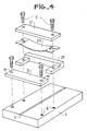
- a support 1 is provided with a V 2 for positioning optical fibers.
- the V is the optimal shape for a reference surface.
- the fiber is kept centered by geometric contact with two reference points.
- the connection is obtained by means of a so-called elastic flange 4 and possibly a flange 3 which are intended to be screwed into threads 6 of the support 1 by means of screws 5.
- the flange 3 is in the form of a flat plate provided with two bores 11.
- the elastic flange 4 assumes in section the general shape of a U having a central branch 7 and two lateral branches 8 bored at 9.
- the two branches 8 of the U join by an elastic and thin wall 10 of length L and thickness e l .
- This wall is arched outwards and protrudes by a distance of flat reference surfaces formed by the ends 8 ′ of the U.
- the arched shape of the wall 10 makes it possible to direct the fibers at the bottom of the V and to avoid overlapping of the fibers.
- the first operation consists in preparing one of the optical fibers. To do this, the outer protective sheath is removed over a short length at the end thereof, while retaining the optical sheath. The fiber thus prepared is positioned in the V marked in 2 and it is held in position by tightening the flange 3 at a level where the sheath has not been removed. As the fiber is still coated with its mechanical protection sheath, for example in epoxy or silicone, the tightening of the flange 3 does not bring any constraints at the level of the fiber itself. Furthermore, the presence of the flange 3 facilitates the establishment of the connection, since it maintains in position the first fiber during the presentation of the second fiber.
- the flat flange can be subsequently dismantled.
- the elastic flange 4 is screwed onto the support l, the two optical fibers are held in position in the V by an elastic restoring force due to the elastic deformation of the wall 10. This force is exerted on the stripped part of the fibers , which must therefore correspond to the width of the elastic flange 4.
- the parameters which define the wall 10 are chosen in such a way that the force applied to the fibers is low enough not to produce such drawbacks.
- the elastic flange 4 has been produced from an unreinforced polycarbonate (for example MAKROLON brand from the company BAYER). It has a density of 1.2 to 1.24 and a modulus of elasticity of 22,000 Kg / cm2. It is easily moldable and has good flexural strength and good dimensional stability.
- the length L of the wall 10 is 7 mm, its thickness e l of about 0.35 mm, and the excess of, of the order of 0.2 mm, for an optical fiber of 125 microns in diameter protruding 20 to 40 microns from a V-shaped groove (see Figure 2b).
- connection On a measurement bench, 50 connections were tested, performed as above, from the cleavage of a fiber with a hard optical sheath of a cable and placed end to end at both ends. For 46 of these, the attenuation due to the connection was less than 0.1 dB, that is to say practically not measurable.
- connection can therefore be used as a reference for a test bench for attenuation of the connectors.
- the steel chosen is a spring steel of Cu-Be alloy
- the thickness e 2 is 0.2 mm
- the projection relative to the lower part of the flange 21 of 0.2 mm.
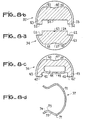
- FIG. 6a and 6b which show the flange 21 respectively in side view and from above, it takes the shape of a U whose central branch 26 is thicker than the two lateral branches 27 so as to position the elastic piece 20.
- the lateral branches 27 each have a bore 29 and a chamfer 28 located on the internal side of each branch 27. The purpose of this chamfer 28 is to let the junction zone pass between the flat portion 24 and the arched portion 25 of the part. elastic 20.
- the arched portion 25 of the elastic piece 20 exceeds by a given amount the lower part 27 ′ of the flange 21.
- the elastic force of support on the optical fibers is thus determined by the mechanical characteristics of the assembly as in the case of FIG.
- the realization of the connection of the optical fibers implements the same steps as in the case of FIG.
- the flange 35 ( Figure 8b), which plays the role of the flange 3 of Figure la, has a lower flat face 52 in which is formed a groove 54 whose width corresponds to that of the upper surface 64 of the support 34, the lower surface 52 also coming into abutment in the notches 62.
- the central part of the flange 35 has, as for the support 34, a cylindrical contour and its upper part consists of a flat 51 provided with a notch 51 'in the form of V intended to receive a branch of a clip 37.
- the flange 35 is provided with a cylindrical contour 53, the diameter of which greater than that of the central part 50 corresponds to the internal diameter of the half shell 32.
- the central part 40 of the elastic flange 36 has a generally cylindrical outline except at its upper part, which has a flat 41 in which is formed a notch 41 ′ allowing to receive a branch of a clip 37.
- the central part 40 has at its lower part a cavity 44 which borders the elastic membrane 45.
- a cylindrical contour 43 is formed, the outside diameter of which is greater than that of the central part 40, corresponds to the inside diameter of the half - shell 32.
- connection of two optical fibers implements the same operations as in the case of the preceding embodiments, the flanges 35 and 36 being fixed to the support 34 by means of a clip 37 shown in FIG. 8d.
- This has a central portion 70 curved to a diameter corresponding to that of the central parts 40, 50 and 60.
- the central part 70 has on each side an elbow 71 which is extended by a straight part 72 directed inwards.
- Each straight part 72 is extended by a bend 73 and an end portion 74 directed outwards, the assembly 72, 73 and 74 being intended to be housed in the V-shaped notches 41 ′, 51 ′ and 61 ′ .
- FIGS. 9a and 9b show respectively in top view and in section a support element for optical fiber intended for multiple connection and comprises a block 80 of width 1 and length L 1 on the upper surface of which grooves 82 are formed. V-shaped bordered at each end by grooves 81 also V-shaped but of larger size so as to facilitate the presentation of the optical fibers.
- This support element is intended to be inserted in a central support shown in section in FIG. 10.
- This comprises a block 83 having a flat upper surface 84 in which is formed a groove 85 whose width 1 corresponds to that of the support element described above.
- the upper surface 84 also includes threads 84 'intended for fixing the flange or flanges of the connection device.
- FIGS. Ua to llc respectively represent a top view, in section AA and in section BB, an embodiment of an elastic flange intended to be mounted on the support described in FIG. 10.
- the elastic flange has two lateral flanges 90. These are interconnected at each of their ends by sections 91 of rectangular shape in which are formed bores 92. These sections 91 do not extend to the upper surface lateral flanges 90 in order to leave a space available for the screw heads in the bores 92.
- an elastically deformable membrane which extends from a flange 90 to to the other. This consists of two parallel walls 93 each of which extends downward the side edges 90.
- the vertical walls 93 are extended by converging inclined walls 94 which are connected together by a flat portion 95.
- This portion 95 is arranged in such a way that it protrudes from a distance d 'from the lower plane 91' of the sections 91. In this way, when the elastic flange is mounted on the support 83, by mounting the screws in the threads 84 'through the bores 92 , the flat portion 95 presses the optical fibers in the grooves 82 over the entire length 1.
- the connection is advantageously carried out in the following manner.
- the fibers at the end of two cables to be connected are mounted in position on a lateral support (not shown) and provided with V-shaped grooves having the same spacing as those of the central support. They are prepared using a tool for collective breakage of optical fibers as described in French patent application 80 16 917 filed on July 31, 1980 by the Applicant.
- Each lateral support is made in such a way deny that the fibers protrude after breaking a quantity precisely determined.
- the lateral supports are then mounted on each side of the block 83 of the central support.
- the optical fibers are then positioned opposite one another. It only remains to mount the elastic flange (FIGS. 11 a to 11 c) with possible interposition of an index liquid.
- the elastic flange shown in Figures 11a to 11c can be produced by molding.
- the material is an uncharged polycarbonate (MAKROLON brand from the company BAYER).
- the elastic membrane has a length 1 equal to II mm, a constant thickness e l equal to 0.3 mm, the portion 95 has a width of 1.5 mm for a spacing of 7 mm between the side walls 93, and the protrusion d 'is equal to 0.2 mm for optical fibers of 125 microns in diameter and protruding from 20 to 40 microns from the V-shaped grooves
- an elastic flange comprising an elastically deformable central region and a non-elastically deformable peripheral region which serves as a stop when tightening the elastic flange.
- the clamping of the flange is elastic and the pressing force is sufficient to prevent any movement from one fiber to another without generating constraints liable to alter the quality of the transmission.
- the clamping of the flange is dynamometric and the bearing force on the fibers remains constant so that the quality of the transmission by the fibers remains unaltered.
- the invention is not limited to the embodiments explicitly described and exemplified.
- other materials can be used to make the flanges and in particular the elastic flanges.
- all elastic materials with good mechanical properties can be used.
Abstract
Description
La présente invention a pour objet un dispositif de raccordement de fibres optiques.The present invention relates to a device for connecting optical fibers.
Les fibres optiques de hautes performances (atténuation de l'ordre de quelques décibels par kilomètre) sont très sensibles aux contraintes. Ainsi, l'atténuation produite au niveau d'un raccordement peut être multiplié par un facteur pouvant aller environ jusqu'à 4 dû à l'apport de contraintes sur les fibres.High performance optical fibers (attenuation of the order of a few decibels per kilometer) are very sensitive to constraints. Thus, the attenuation produced at the level of a connection can be multiplied by a factor which can go up to approximately 4 due to the contribution of stresses on the fibers.
La présente invention a pour objet un dispositif de raccordement de fibres optiques permettant de minimiser l'apport de contraintes sur les fibres optiques au niveau du raccordement.The present invention relates to an optical fiber connection device making it possible to minimize the contribution of stresses on the optical fibers at the connection.
Le dispositif selon l'invention est caractérisé en ce qu'il comporte une surface de référence destinée à disposer bout-à-bout au moins une paire de fibres optiques et une bride élastique pour maintenir en place les fibres optiques sous l'action d'une force élastique transversale d'intensité donnée.The device according to the invention is characterized in that it comprises a reference surface intended to have end-to-end at least one pair of optical fibers and an elastic flange to hold the optical fibers in place under the action of a transverse elastic force of given intensity.
La surface de référence peut comporter au moins une rainure adaptée à la forme des fibres. Ladite rainure peut être en forme de V.The reference surface may include at least one groove adapted to the shape of the fibers. Said groove can be V-shaped.
La bride élastique peut comporter une région centrale élastiquement déformable et une région périphérique présentant des moyens de fixation. Cette région périphérique peut être non déformable élastiquement de manière à servir de butée lors du serrage de la bride élastique. La région centrale élastiquement déformable peut être rapportée dans la bride élastique.The elastic flange may include an elastically deformable central region and a peripheral region having fixing means. This peripheral region can be elastically non-deformable so as to serve as a stop when the elastic flange is tightened. The elastically deformable central region can be added to the elastic flange.
La bride élastique selon l'invention peut être une pièce en matière plastique moulée affectant en coupe la forme générale d'un U dont les branches latérales se rejoignent par une paroi élastique et mince d'épaisseur donnée.The elastic flange according to the invention may be a piece of molded plastic material having in cross section the general shape of a U, the lateral branches of which meet by an elastic and thin wall of given thickness.
Le dispositif peut comporter une bride plate pour maintenir en place au moins une fibre optique située d'un côté du raccordement.The device may include a flat flange to hold at least one optical fiber located on one side of the connection.
Le dispositif peut être constitué de pièces de contour extérieur cylindrique disposées dans un logement ménagé dans deux demi-coquilles.The device can consist of cylindrical outer contour parts arranged in a housing formed in two half-shells.
Pour la réalisation du raccordement de plusieurs fibres optiques, la bride élastique peut comporter deux rebords latéraux reliés entre eux à leurs extrémités et comportant dans leur partie centrale et sur une longueur donnée 1, une membrane élastiquement déformable comportant deux parois parallèles se prolongeant par des parois inclinées convergentes reliées entre elles par une paroi plane destinée à venir s'appuyer contre les fibres optiques lorsque le dispositif est monté.For the connection of several optical fibers, the elastic flange may have two lateral flanges connected to each other at their ends and comprising in their central part and over a given length 1, an elastically deformable membrane comprising two parallel walls extending by walls. converging inclines connected together by a flat wall intended to bear against the optical fibers when the device is mounted.
Le procédé comporte une étape où on prépare des extrémités des fibres optiques à raccorder, une étape où on dispose au moins une première fibre optique sur la surface de référence, une étape où on dispose une deuxième fibre optique en regard de chaque première fibre optique, éventuellement une étape où on positionne la bride élastique sans serrage de manière à positionner les fibres optiques tout en laissant une liberté de déplacement en translation au moins à chaque deuxième fibre optique, une étape où on met en butée l'extrémité de chaque deuxième fibre optique contre l'extrémité de chaque première fibre optique et une étape où on serre en position la bride élastique.The method comprises a step where the ends of the optical fibers to be connected are prepared, a step where at least one first optical fiber is placed on the reference surface, a step where a second optical fiber is placed opposite each first optical fiber, optionally a step where the elastic flange is positioned without clamping so as to position the optical fibers while leaving a freedom of movement in translation at least for each second optical fiber, a step where the end of each second optical fiber is abutted against the end of each first optical fiber and a step where the elastic strap is tightened in position.
L'invention sera mieux comprise à l'aide des exemples de réalisation donnés à titre non limitatif, conjointement avec les figures ci-annexées :
- - la figure la représente en vue éclatée un premier mode de réalisation de l'invention,
- - la figure lb représente un détail de la figure la, à savoir un V de positionnement de fibres optiques,
- - les figures 2a et 2b représentent respectivement en vue latérale et en coupe les brides de positionnement de fibres optiques suivant le mode de réalisation de la figure la,
- - la figure 3 représente en vue latérale une variante de réalisation de la bride représentée à la figure 2b,
- - la figure 4 représente en vue éclatée une autre variante de l'invention,
- - les figures 5a et 5b, 6a et 6b représentent des détails et des pièces du mode de réalisation de la figure 4,
- - la figure 7 représente en coupe un mode de réalisation de l'invention sous forme de connecteur,
- - les figures 8a à 8d représentent des pièces de positionnement des fibres optiques du mode de réalisation de la figure 7,
- - les figures 9a, 9b et 10 représentent un support présentant une pluralité de rainures en forme de V destinées à un raccordement d'une pluralité de fibres optiques,
- - les figures lla à llc représentent une bride adaptée au raccordement d'une pluralité de fibres optiques.
- FIG. 1a represents an exploded view of a first embodiment of the invention,
- FIG. 1b represents a detail of FIG. 1a, namely a V for positioning optical fibers,
- FIGS. 2a and 2b respectively show in side view and in section the flanges for positioning optical fibers according to the embodiment of FIG.
- FIG. 3 shows in side view an alternative embodiment of the flange shown in FIG. 2b,
- FIG. 4 shows in exploded view another variant of the invention,
- FIGS. 5a and 5b, 6a and 6b show details and parts of the embodiment of FIG. 4,
- FIG. 7 represents in section an embodiment of the invention in the form of a connector,
- FIGS. 8a to 8d represent pieces for positioning the optical fibers of the embodiment of FIG. 7,
- FIGS. 9a, 9b and 10 show a support having a plurality of V-shaped grooves intended for connection of a plurality of optical fibers,
- - Figures lla to llc show a flange adapted to the connection of a plurality of optical fibers.
Selon la figure la, un support 1 est pourvu d'un V 2 de positionnement de fibres optiques. Le V est la forme optimale pour une surface de référence. En coupe, la fibre est maintenue centrée par contact géométrique avec deux points de référence. Le raccordement est obtenu grâce à une bride dite élastique 4 et éventuellement une bride 3 qui sont destinées à être vissées dans des taraudages 6 du support 1 grâce à des vis 5.According to Figure la, a support 1 is provided with a
Selon la figure lb, le V 2 de positionnement présente un angle de 90° entre ses parois et il est conçu de telle manière qu'une fibre de diamètre D dépasse de celui-ci d'une hauteur d donnée. Par exemple, pour une fibre de 125 microns d'épaisseur, le dépassement d choisi est situé dans une plage de 20 à 40 microns.According to FIG. 1b, the
Suivant la figure 2a, la bride 3 se présente sous la forme d'une plaque plane pourvue de deux alésages 11. Selon la coupe de la figure 2b, la bride élastique 4 affecte en coupe la forme générale d'un U présentant une branche centrale 7 et deux branches latérales 8 alésées en 9. Les deux branches 8 du U se rejoignent par une paroi élastique et mince 10 de longueur L et d'épaisseur el. Cette paroi est cambrée vers l'extérieur et dépasse d'une distance d' des surfaces planes de référence constituées par les extrémités 8' des U.La forme cambrée de la paroi 10 permet de diriger les fibres au fond du V et d'éviter les chevauchements des fibres.According to Figure 2a, the
On va maintenant décrire une opération de raccordement de deux fibres optiques suivant ce mode de réalisation. La première opération consiste à préparer une des fibres optiques. Pour ce faire, on enlève sur une courte longueur à l'extrémité de celle-ci la gaine extérieure de protection, tout en conservant la gaine optique. La fibre ainsi préparée est positionnée dans le V repéré en 2 et elle est maintenue en position par serrage de la bride 3 à un niveau où la gaine n'a pas été enlevée. Comme la fibre est encore revêtue de sa gaine de protection mécanique, par exemple en époxy ou en silicone, le serrage de la bride 3 n'apporte pas de contraintes au niveau de la fibre proprement dite. Par ailleurs, la présence de la bride 3 facilite la mise en place du raccordement, puisqu'elle maintient en position la première fibre lors de la présentation de la deuxième fibre. On prépare ensuite l'extrémité de l'autre fibre et on la positionne dans le V 2 au voisinage de l'extrémité de la première fibre, avec interposition d'une goutte de liquide adaptateur d'indice. Le liquide adaptateur d'indice améliore l'atténuation du raccordement et facilite la manipulation. On met en place la bride élastique 4 sans serrage. Le positionnement de la bride élastique 4 sans serrage permet de plaquer la deuxième fibre au fond du V tout en laissant à celle-ci une liberté de déplacement en translation. On met ensuite. en butée manuellement l'extrémité de la deuxième fibre contre l'extrémité de la première. Cette opération se fait facilement et correctement grâce au plaquage de la deuxième fibre procurée par la deuxième bride. On serre ensuite la bride 4 par vissage des vis 5 dans les taraudages 6. La bride plate peut être ultérieurement démontée. Lorsque la bride élastique 4 est vissée sur le support l, les deux fibres optiques sont maintenues en position dans le V par une force de rappel élastique due à la déformation élastique de la paroi 10. Cette force s'exerce sur la partie dénudée des fibres, laquelle doit donc correspondre à la largeur de la bride élastique 4. Comme des forces de çontraintes appliquées transversalement aux fibres optiques seraient susceptibles de produire une atténuation, les paramètres qui définissent la paroi 10 sont choisis de telle manière que la force appliquée sur les fibres soit suffisamment faible pour ne pas produire de tels inconvénients.We will now describe an operation for connecting two optical fibers according to this embodiment. The first operation consists in preparing one of the optical fibers. To do this, the outer protective sheath is removed over a short length at the end thereof, while retaining the optical sheath. The fiber thus prepared is positioned in the V marked in 2 and it is held in position by tightening the
A titre d'exemple, on a réalisé la bride élastique 4 en un polycarbonate non renforcé (par exemple marque MAKROLON de la Société BAYER). Il présente une densité de 1,2 à 1,24 et un module d'élasticité de 22 000 Kg/cm2. Il est facilement moulable et possède une bonne résistance à la flexion et une bonne stabilité dimensionnelle. Dans cet exemple de réalisation, la longueur L de la paroi 10 est de 7 mm, son épaisseur el de 0,35 mm environ, et le dépassement d', de l'ordre de 0,2 mm, pour une fibre optique de 125 microns de diamètre dépassant de 20 à 40 microns d'une rainure en forme de V (voir figure 2b).By way of example, the
Sur un banc de mesure, on a testé 50 raccordements réalisés comme ci-dessus à partir du clivage d'une fibre à gaine optique dure d'un câble et mise bout-à-bout des deux extrémités. Pour 46 de ceux-ci, l'atténuation due au raccordement était inférieure à 0,1 dB, c'est-à-dire pratiquement non mesurable.On a measurement bench, 50 connections were tested, performed as above, from the cleavage of a fiber with a hard optical sheath of a cable and placed end to end at both ends. For 46 of these, the attenuation due to the connection was less than 0.1 dB, that is to say practically not measurable.
Un tel raccordement peut donc être utilisé comme référence pour un banc de test de l'atténuation des connecteurs.Such a connection can therefore be used as a reference for a test bench for attenuation of the connectors.
De la description et de l'exemple ci-dessus, il ressort que la force exercée sur les fibres optiques situées dans le V ne dépend que des caractéristiques géométriques de la bride, de la fibre et du V. Elle est par contre indépendante de la force de serrage. En effet, les extrémités 8' des branches 8 du U viennent en butée sur la paroi plane du support 1 et tout serrage ultérieur des vis 5 ne transmet à la paroi 10 aucune force supplémentaire de compression.From the description and example above, it appears that the force exerted on the optical fibers located in the V depends only on the geometrical characteristics of the flange, the fiber and the V. It is on the other hand independent of the clamping force. In fact, the
Selon la figure 3, la bride élastique présente un bloc central 7' et deux branches latérales 8 alésées en 9'. Les deux branches 8' sont séparées par une cavité comportant une partie centrale plane 14 et deux logements 13 destinés à recevoir une plaque élastique 10' qui joue le rôle de la paroi 10 de la figure 2b.According to Figure 3, the elastic flange has a central block 7 'and two
Selon la figure 4, la bride élastique est obtenue à partir d'une bride plate 3', et d'un support 21 entre lesquels est disposée une pièce élastique 20. L'ensemble est monté par vissage dans les taraudages 6 du support 1. Selon les figures 5a et 5b, qui représentent la pièce élastique 20 en vue de dessus et en vue latérale, celle-ci comporte deux portions latérales planes 24 ouvertes en 22 jusqu'à des arrondis 23 destinés à recevoir les vis 5 et une portion centrale cambrée 25 qui présente en vue latérale la forme d'un arc de cercle de rayon R. La pièce élastique 20 a une épaisseur e2. Elle peut être métallique et obtenue par emboutissage d'une plaque d'acier.According to FIG. 4, the elastic flange is obtained from a flat flange 3 ', and from a
A titre d'exemple, l'acier choisi est un acier à ressort en alliage Cu-Be, l'épaisseur e2 est de 0,2 mm, et le dépassement par rapport à la partie inférieure de la bride 21 de 0,2 mm.For example, the steel chosen is a spring steel of Cu-Be alloy, the thickness e 2 is 0.2 mm, and the projection relative to the lower part of the
Selon les figures 6a et 6b qui représentent la bride 21 respectivement en vue latérale et de dessus, celle-ci affecte la forme d'un U dont la branche centrale 26 est plus épaisse que les deux branches latérales 27 de manière à positionner la pièce élastique 20. Les branches latérales 27 présentent chacune un alésage 29 et un chanfrein 28 situé du côté interne de chaque branche 27. Ce chanfrein 28 a pour but de laisser passer la zone de jonction entre la portion plane 24 et la portion cambrée 25 de la pièce élastique 20. Lorsque l'ensemble est monté, la portion cambrée 25 de la pièce élastique 20 dépasse d'une quantité donnée de la partie inférieure 27' de la bride 21. La force élastique d'appui sur les fibres optiques est ainsi déterminée par les caractéristiques mécaniques de l'ensemble comme dans le cas de la figure la. Par ailleurs, la réalisation du raccordement des fibres optiques met en oeuvre les mêmes étapes que dans le cas de la figure la.According to Figures 6a and 6b which show the
La figure 7 représente un dispositif de raccordement selon l'invention sous la forme d'un connecteur optique. Il comporte un boîtier extérieur constitué par deux demi-coquilles 31 et 32 fixées entre elles par des vis non représentées. Les fibres gainées sont amenées à la partie active du connecteur par des brides présentant une partie cylindrique 33 se terminant par une partie de diamètre plus importante 33' qui est bloquée dans des logements correspondant des demi-coquilles 31 et 32. Un support 34 et des brides 35 et 36 sont emprisonnés entre les demi-coquilles, dans un logement cylindrique. Les brides 35 et 36 sont rendues solidaires du support 34 par des clips 37. Le support 34 s'étend sur toute la longueur du logement disponible entre les demi-coquilles 31 et 32.FIG. 7 represents a connection device according to the invention in the form of an optical connector. It comprises an external housing constituted by two half-
La bride 34 (figure 8a) comporte un V 65 de positionnement des fibres, lequel est disposée sur sa face supérieure 64. La face supérieure 64 est bordée de deux entailles 62. Sa partie centrale 60 est de forme générale semi-circulaire, sauf à sa partie inférieure où elle présente un méplat 61 au centre duquel est ménagée une entaille 61' en forme de V destinée à recevoir une branche d'un clip 37. Le support 34 présente à ses extrémités, et éventuellement en son milieu une région cylindrique 63 de diamètre plus grand, lequel correspond au diamètre intérieur de la demi-coquille cylindrique 31.The flange 34 (FIG. 8a) comprises a
La bride 35 (figure 8b), qui joue le rôle de la bride 3 de la figure la, comporte une face plane inférieure 52 dans laquelle est ménagée une rainure 54 dont la largeur correspond à celle de la surface supérieure 64 du support 34, la surface inférieure 52 venant par ailleurs en butée dans les entailles 62. La partie centrale de la bride 35 présente comme pour le support 34, un contour cylindrique et sa partie supérieure est constituée par un méplat 51 pourvu d'une entaille 51' en forme de V destinée à recevoir une branche d'un clip 37. A chacune de ses extrémités, la bride 35 est pourvue d'un contour cylindrique 53, dont le diamètre plus grand que celui de la partie centrale 50 correspond au diamètre intérieur de la demi-coquille 32.The flange 35 (Figure 8b), which plays the role of the
Selon la figure 8c, la bride élastique 36, qui remplit la fonction de la bride élastique 4 de la figure la, présente une face inférieure 45 constituée par une membrane élastique légèrement cambrée (voir la description de la membrane élastique 10 à la figure 2B). La membrane élastique 45 est bordée de deux rebords 42 présentant une surface plane inférieure 42'. Les rebords 42 sont espacés et dimensionnés de telle manière que les surfaces inférieures 42' viennent en butée au fond des entailles 62 du support 34. Ceci permet de positionner les fibres au niveau de leur raccordement dans le V 65 sans exercer sur elles de contraintes trop importantes, ainsi qu'il a été précédemment expliqué. La partie centrale 40 de la bride élastique 36 a un contour généralement cylindrique sauf à sa partie supérieure, laquelle présente un méplat 41 dans lequel est ménagée une entaille 41' permettant de recevoir une branche d'un clip 37. La partie centrale 40 présente à sa partie inférieure une cavité 44 qui borde la membrane élastique 45. A chacune des extrémités de la bride élastique 36, est ménagé un contour cylindrique 43 dont le diamètre extérieur plus grand que celui de la partie centrale 40, correspond au diamètre intérieur de la demi-coquille 32.According to FIG. 8c, the
Le raccordement de deux fibres optiques met en oeuvre les mêmes opérations que dans le cas des modes de réalisation précédents, les brides 35 et 36 étant fixées sur le support 34 grâce à un clip 37 représenté à la figure 8d. Celui-ci présente une portion centrale 70 recourbée selon un diamètre correspondant à celui des parties centrales 40, 50 et 60. La partie centrale 70 présente de chaque côté un coude 71 qui se prolonge par une partie droite 72 dirigée vers l'intérieur. Chaque partie droite 72 se prolonge par un coude 73 et une portion terminale 74 dirigée vers l'extérieur, l'ensemble 72, 73 et 74 étant destiné à venir se loger dans les entailles en forme de V 41', 51' et 61'.The connection of two optical fibers implements the same operations as in the case of the preceding embodiments, the
Les figures 9a et 9b représentent respectivement en vue de dessus et en coupe un élément de support pour fibre optique destiné à un raccordement multiple et comporte un bloc 80 de largeur 1 et de longueur L1 à la surface supérieure duquel sont ménagées des rainures 82 en forme de V bordées à chaque extrémité par des rainures 81 également en forme de V mais de dimension plus importante de manière à faciliter la présentation des fibres optiques. Cet élément de support est destiné à être inséré dans un support central représenté en coupe à la figure 10. Celui-ci comporte un bloc 83 présentant une surface supérieure plane 84 dans laquelle est ménagée une rainure 85 dont la largeur 1 correspond à celle de l'élément de support précédemment décrit. La surface supérieure 84 comporte également des taraudages 84' destinés à la fixation de la ou des brides du dispositif de raccordement.FIGS. 9a and 9b show respectively in top view and in section a support element for optical fiber intended for multiple connection and comprises a block 80 of width 1 and length L 1 on the upper surface of which
Les figures Ua à llc représentent respectivement en vue de dessus, en coupe AA et en coupe BB un mode de réalisation d'une bride élastique destinée à être montée sur le support décrit à la figure 10.FIGS. Ua to llc respectively represent a top view, in section AA and in section BB, an embodiment of an elastic flange intended to be mounted on the support described in FIG. 10.
La bride élastique comporte deux rebords latéraux 90. Ceux-ci sont reliés entre eux à chacune de leurs extrémités par des sections 91 de forme rectangulaire dans lesquelles sont ménagés des alésages 92. Ces sections 91 ne s'étendent pas jusqu'à la surface supérieure des rebords latéraux 90 afin de laisser un espace disponible pour les têtes de vis dans les alésages 92. Dans la partie centrale des rebords latéraux 90, et sur une longueur 1 est disposée une membrane élastiquement déformable qui s'étend depuis un rebord 90 jusqu'à l'autre. Celle-ci se compose de deux parois parallèles 93 dont chacune prolonge vers le bas les rebords latéraux 90. Les parois verticales 93 se prolongent par des parois inclinées convergentes 94 qui sont reliées entre elles par une portion plane 95. Cette portion 95 est disposée de telle manière qu'elle dépasse d'une distance d' du plan inférieur 91' des sections 91. De cette manière, lorsque la bride élastique est montée sur le support 83, par montage des vis dans les taraudages 84' à travers les alésages 92, la portion plane 95 vient appuyer les fibres optiques dans les rainures 82 sur toute la longueur 1.The elastic flange has two
Le raccordement est avantageusement effectué de la manière suivante. Les fibres à l'extrémité de deux câbles à raccorder sont montées en position sur un support latéral (non représenté) et pourvu de rainures en forme de V présentant le même écartement que celles du support central. Elles sont préparées grâce à un outillage de cassure collective de fibres optiques tel que décrit dans la demande de brevet français 80 16 917 déposée le 31 juillet 1980 par la Demanderesse. Chaque support latéral est réalisé de telle ma- nière que les fibres en dépassent après cassure d'une quantité![]()
![]()
La bride élastique représentée sur les figures lla à llc peut être réalisée par moulage. A titre d'exemple, la matière est un polycarbonate non chargé (marque MAKROLON de la Société BAYER). La membrane élastique a une longueur 1 égale à Il mm, une épaisseur el constante égale à 0,3 mm, la portion 95 a une largeur de 1,5 mm pour un écartement de 7 mm entre les parois latérales 93, et le dépassement d' est égal à 0,2 mm pour des fibres optiques de 125 microns de diamètre et dépassant de 20 à 40 microns des rainures en forme de V.The elastic flange shown in Figures 11a to 11c can be produced by molding. For example, the material is an uncharged polycarbonate (MAKROLON brand from the company BAYER). The elastic membrane has a length 1 equal to II mm, a constant thickness e l equal to 0.3 mm, the
La description ci-dessus met en évidence l'avantage particulier que présente la mise en oeuvre d'une bride élastique comportant une région centrale élastiquement déformable et une région périphérique non déformable élastiquement et qui sert de butée lors du serrage de la bride élastique. Dans un premier temps, le serrage de la bride est élastique et la force d'appui est suffisante pour interdire tout mouvement d'une fibre à l'autre sans engendrer de contraintes susceptibles d'altérer la qualité de la transmission. Dans un second temps, le serrage de la bride est dynamométrique et la force d'appui sur les fibres reste constante de telle sorte que la qualité de la transmission par les fibres reste inaltérée.The above description highlights the particular advantage of using an elastic flange comprising an elastically deformable central region and a non-elastically deformable peripheral region which serves as a stop when tightening the elastic flange. Initially, the clamping of the flange is elastic and the pressing force is sufficient to prevent any movement from one fiber to another without generating constraints liable to alter the quality of the transmission. In a second step, the clamping of the flange is dynamometric and the bearing force on the fibers remains constant so that the quality of the transmission by the fibers remains unaltered.
L'invention ne se limite pas aux modes de réalisation explicitement décrits et exemplifiés. Ainsi, on peut utiliser d'autres matériaux pour réaliser les brides et notamment les brides élastiques. En effet, tous les matériaux élastiques présentant de bonnes propriétés mécaniques peuvent être utilisés. Pour obtenir des forces de pression comparables à celles des exemples mentionnés ci-dessus, il suffit d'adapter les dimensions des parois élastiques en tenant compte du module d'élasticité du matériau utilisé.The invention is not limited to the embodiments explicitly described and exemplified. Thus, other materials can be used to make the flanges and in particular the elastic flanges. Indeed, all elastic materials with good mechanical properties can be used. To obtain pressure forces comparable to those of the examples mentioned above, it suffices to adapt the dimensions of the elastic walls taking into account the modulus of elasticity of the material used.
Claims (14)
Applications Claiming Priority (2)
| Application Number | Priority Date | Filing Date | Title |
|---|---|---|---|
| FR8205441 | 1982-03-30 | ||
| FR8205441A FR2524654B1 (en) | 1982-03-30 | 1982-03-30 | OPTICAL FIBER CONNECTION DEVICE AND METHOD OF IMPLEMENTING SAME |
Publications (2)
| Publication Number | Publication Date |
|---|---|
| EP0090724A1 true EP0090724A1 (en) | 1983-10-05 |
| EP0090724B1 EP0090724B1 (en) | 1987-02-04 |
Family
ID=9272566
Family Applications (1)
| Application Number | Title | Priority Date | Filing Date |
|---|---|---|---|
| EP19830400593 Expired EP0090724B1 (en) | 1982-03-30 | 1983-03-22 | Apparatus for joining fibres together and method of putting it into use |
Country Status (3)
| Country | Link |
|---|---|
| EP (1) | EP0090724B1 (en) |
| DE (1) | DE3369734D1 (en) |
| FR (1) | FR2524654B1 (en) |
Cited By (11)
| Publication number | Priority date | Publication date | Assignee | Title |
|---|---|---|---|---|
| FR2556847A1 (en) * | 1983-12-16 | 1985-06-21 | Socapex | SEMI-PERMANENT CONNECTION DEVICE FOR OPTICAL FIBERS AND METHOD FOR ITS IMPLEMENTATION |
| FR2579772A1 (en) * | 1985-03-29 | 1986-10-03 | Socapex | OPTICAL DUPLEXER WITH INTEGRATED SEMI-PERMANENT OPTICAL CONNECTION |
| US4615097A (en) * | 1983-10-05 | 1986-10-07 | Cabloptic S.A. & Fondation Suisse pour la Recherche en Microtechnique | Apparatus for precise positioning of optical components |
| FR2586304A1 (en) * | 1985-08-13 | 1987-02-20 | Radiall Ind | DEVICE FOR REVERSIBLELY ESTABLISHING A CONNECTION BETWEEN TWO OPTICAL FIBERS, MOBILE SHEETS, AND DEVICE FOR FIXING THE SAME, AND METHOD FOR PREPARING AN ADAPTED OPTICAL FIBER TERMINATION |
| FR2593294A1 (en) * | 1986-01-23 | 1987-07-24 | Alsthom Cgee | CONNECTOR FOR OPTICAL FIBERS |
| EP0154689B1 (en) * | 1984-02-09 | 1990-05-02 | Siemens Aktiengesellschaft | Apparatus for the detachable connection of a light guide to an optoelectronic element |
| EP0462710A1 (en) * | 1990-06-20 | 1991-12-27 | Hughes Aircraft Company | Optical fiber holder |
| WO1999042876A1 (en) * | 1998-02-23 | 1999-08-26 | Huber & Suhner Ag | Positioning system for positioning and attaching optical fibres and connectors provided with this positioning system |
| EP0806688B1 (en) * | 1996-05-09 | 2003-03-26 | France Telecom | Centering device, process for connecting a plurality of fibres to a multicore fibre and coupler/distributor made thereby |
| US7512305B2 (en) * | 2006-02-08 | 2009-03-31 | Bookham Technology Plc | Precision optical fiber clamp |
| CN102073105A (en) * | 2010-12-07 | 2011-05-25 | 福州高意通讯有限公司 | Optical fiber holder |
Citations (7)
| Publication number | Priority date | Publication date | Assignee | Title |
|---|---|---|---|---|
| US3885859A (en) * | 1974-06-24 | 1975-05-27 | Northern Electric Co | Optical fibre connectors |
| US4102561A (en) * | 1975-07-02 | 1978-07-25 | Corning Glass Works | Optical waveguide connector |
| GB1520679A (en) * | 1977-02-18 | 1978-08-09 | Bicc Ltd | Jointing optical fibres |
| GB2009440A (en) * | 1977-11-24 | 1979-06-13 | Comp Generale Electricite | Fibre-to-fibre connector for miltifibre optical fibre cables |
| WO1980000619A1 (en) * | 1978-09-01 | 1980-04-03 | Gte Sylvania Inc | Optical fiber connector |
| EP0021871A1 (en) * | 1979-06-08 | 1981-01-07 | Thomson-Csf | Method of mounting an optical fibre in a ferrule and ferrule obtained by carrying out the process |
| FR2487812A1 (en) | 1980-07-31 | 1982-02-05 | Socapex | TOOLING OF COLLECTIVE CASSURE OF OPTICAL FIBERS |
Family Cites Families (1)
| Publication number | Priority date | Publication date | Assignee | Title |
|---|---|---|---|---|
| FR2446496A1 (en) * | 1977-11-24 | 1980-08-08 | Comp Generale Electricite | Coupler for multiline optical cables - holds individual lines between adjacent rods maintained vertically in position by compressible pad |
-
1982
- 1982-03-30 FR FR8205441A patent/FR2524654B1/en not_active Expired
-
1983
- 1983-03-22 EP EP19830400593 patent/EP0090724B1/en not_active Expired
- 1983-03-22 DE DE8383400593T patent/DE3369734D1/en not_active Expired
Patent Citations (7)
| Publication number | Priority date | Publication date | Assignee | Title |
|---|---|---|---|---|
| US3885859A (en) * | 1974-06-24 | 1975-05-27 | Northern Electric Co | Optical fibre connectors |
| US4102561A (en) * | 1975-07-02 | 1978-07-25 | Corning Glass Works | Optical waveguide connector |
| GB1520679A (en) * | 1977-02-18 | 1978-08-09 | Bicc Ltd | Jointing optical fibres |
| GB2009440A (en) * | 1977-11-24 | 1979-06-13 | Comp Generale Electricite | Fibre-to-fibre connector for miltifibre optical fibre cables |
| WO1980000619A1 (en) * | 1978-09-01 | 1980-04-03 | Gte Sylvania Inc | Optical fiber connector |
| EP0021871A1 (en) * | 1979-06-08 | 1981-01-07 | Thomson-Csf | Method of mounting an optical fibre in a ferrule and ferrule obtained by carrying out the process |
| FR2487812A1 (en) | 1980-07-31 | 1982-02-05 | Socapex | TOOLING OF COLLECTIVE CASSURE OF OPTICAL FIBERS |
Non-Patent Citations (2)
| Title |
|---|
| ABSTRACT OF NEW TECHNOLOGY FROM THE AIR FORCE SYSTEMS COMMAND, no. NTN-78/0446, 1978, USA * |
| IBM TECHNICAL DISCLOSURE BULLETIN, vol. 22, no. 2, juillet 1979, pages 686-687, New York, USA * |
Cited By (17)
| Publication number | Priority date | Publication date | Assignee | Title |
|---|---|---|---|---|
| US4615097A (en) * | 1983-10-05 | 1986-10-07 | Cabloptic S.A. & Fondation Suisse pour la Recherche en Microtechnique | Apparatus for precise positioning of optical components |
| EP0146471A2 (en) * | 1983-12-16 | 1985-06-26 | Socapex | Apparatus and method for the semi-permanent connection of optical fibres |
| EP0146471A3 (en) * | 1983-12-16 | 1985-07-31 | Socapex | Apparatus and method for the semi-permanent connection of optical fibres |
| FR2556847A1 (en) * | 1983-12-16 | 1985-06-21 | Socapex | SEMI-PERMANENT CONNECTION DEVICE FOR OPTICAL FIBERS AND METHOD FOR ITS IMPLEMENTATION |
| EP0154689B1 (en) * | 1984-02-09 | 1990-05-02 | Siemens Aktiengesellschaft | Apparatus for the detachable connection of a light guide to an optoelectronic element |
| FR2579772A1 (en) * | 1985-03-29 | 1986-10-03 | Socapex | OPTICAL DUPLEXER WITH INTEGRATED SEMI-PERMANENT OPTICAL CONNECTION |
| EP0197841A1 (en) * | 1985-03-29 | 1986-10-15 | Socapex | Optical duplexer for integrated semi-permanent optical connection |
| US4767180A (en) * | 1985-08-13 | 1988-08-30 | Radiall Industrie | Device for making a non-permanent connection between two optical fibers, mobile plug members and holding device for same, and appropriate method of preparing an optical fiber termination |
| FR2586304A1 (en) * | 1985-08-13 | 1987-02-20 | Radiall Ind | DEVICE FOR REVERSIBLELY ESTABLISHING A CONNECTION BETWEEN TWO OPTICAL FIBERS, MOBILE SHEETS, AND DEVICE FOR FIXING THE SAME, AND METHOD FOR PREPARING AN ADAPTED OPTICAL FIBER TERMINATION |
| EP0215696A1 (en) * | 1985-08-13 | 1987-03-25 | Radiall Industrie | Reversible fibre-optic connection with a mobile plug, immobilisation device for said connection system and method of producing an adapted fibre-optic end piece |
| FR2593294A1 (en) * | 1986-01-23 | 1987-07-24 | Alsthom Cgee | CONNECTOR FOR OPTICAL FIBERS |
| EP0232754A1 (en) * | 1986-01-23 | 1987-08-19 | Entrelec Sa | Coupler for optical fibres |
| EP0462710A1 (en) * | 1990-06-20 | 1991-12-27 | Hughes Aircraft Company | Optical fiber holder |
| EP0806688B1 (en) * | 1996-05-09 | 2003-03-26 | France Telecom | Centering device, process for connecting a plurality of fibres to a multicore fibre and coupler/distributor made thereby |
| WO1999042876A1 (en) * | 1998-02-23 | 1999-08-26 | Huber & Suhner Ag | Positioning system for positioning and attaching optical fibres and connectors provided with this positioning system |
| US7512305B2 (en) * | 2006-02-08 | 2009-03-31 | Bookham Technology Plc | Precision optical fiber clamp |
| CN102073105A (en) * | 2010-12-07 | 2011-05-25 | 福州高意通讯有限公司 | Optical fiber holder |
Also Published As
| Publication number | Publication date |
|---|---|
| FR2524654A1 (en) | 1983-10-07 |
| DE3369734D1 (en) | 1987-03-12 |
| FR2524654B1 (en) | 1985-10-04 |
| EP0090724B1 (en) | 1987-02-04 |
Similar Documents
| Publication | Publication Date | Title |
|---|---|---|
| EP0116481B1 (en) | Device for rapidly connecting optical fibre ends | |
| CA1131952A (en) | Connector for optical fiber linles | |
| CA1126552A (en) | Method and device for connecting optical fibres in a flat cable | |
| EP1621905B1 (en) | Optical fibre connector | |
| EP0122169B1 (en) | Method and apparatus for joining optical fibres | |
| EP0441676B1 (en) | Connector for optical fibres | |
| EP0090724B1 (en) | Apparatus for joining fibres together and method of putting it into use | |
| EP0103527B1 (en) | Apparatus for connecting the extremities of optical fibres | |
| EP0051519B1 (en) | Ferrule for an optical fibre connector, and connector providing such a ferrule | |
| EP0158561A2 (en) | Connector for an optical fibre and a photodetector or light emitter; method for positioning such elements | |
| FR2461966A1 (en) | DISMANTLING COUPLING FOR COUPLING A PAIR OF PHOTOCONDUCTIVE FIBERS | |
| FR2606166A1 (en) | OPTICAL FIBER SUPPORT AND DEVICE COMPRISING THE SAME | |
| EP0097575A1 (en) | Plug for an optical fibre connector, and a connector comprising such a plug | |
| EP0063068A1 (en) | Process for concentrically mounting an optical fibre in a ferrule | |
| CA1257994A (en) | Fiber optic receiver part for coupling device, and manufacturing process of said device | |
| EP0014610A1 (en) | Detachable coupling for optical fibres | |
| WO1992002836A1 (en) | Optical fibre connector | |
| EP0146471B1 (en) | Apparatus and method for the semi-permanent connection of optical fibres | |
| FR2530829A1 (en) | OPTICAL FIBER CONNECTOR | |
| EP0768548A1 (en) | Device for simplifying the connection of optical fibers | |
| FR2778752A1 (en) | OPTICAL CONNECTOR | |
| EP0051507A1 (en) | Two-ferrules connecting and alignment device for connecting optical fibres, and connector providing such a device | |
| FR2542458A1 (en) | Method and device for connecting optical fibres | |
| FR2488699A1 (en) | Connector for optical fibre, with adjusting mechanism - uses two contacting blocks having hollow sections, forming cavity, receiving sealing material, and permits sliding contact | |
| FR2820789A1 (en) | Mechanical fixing of an optical component, uses deformable holder for optical component, which is pushed into holder and clamped in place by ring slid over holder |
Legal Events
| Date | Code | Title | Description |
|---|---|---|---|
| PUAI | Public reference made under article 153(3) epc to a published international application that has entered the european phase |
Free format text: ORIGINAL CODE: 0009012 |
|
| AK | Designated contracting states |
Kind code of ref document: A1 Designated state(s): DE GB IT NL Designated state(s): DE GB IT NL |
|
| 17P | Request for examination filed |
Effective date: 19831112 |
|
| GRAA | (expected) grant |
Free format text: ORIGINAL CODE: 0009210 |
|
| ITF | It: translation for a ep patent filed |
Owner name: ING. ZINI MARANESI & C. S.R.L. |
|
| AK | Designated contracting states |
Kind code of ref document: B1 Designated state(s): DE GB IT NL |
|
| REF | Corresponds to: |
Ref document number: 3369734 Country of ref document: DE Date of ref document: 19870312 |
|
| PLBI | Opposition filed |
Free format text: ORIGINAL CODE: 0009260 |
|
| 26 | Opposition filed |
Opponent name: SIEMENS AKTIENGESELLSCHAFT, BERLIN UND MUENCHEN Effective date: 19871104 |
|
| NLR1 | Nl: opposition has been filed with the epo |
Opponent name: SIEMENS AKTIENGESELLSCHAFT |
|
| PLBN | Opposition rejected |
Free format text: ORIGINAL CODE: 0009273 |
|
| STAA | Information on the status of an ep patent application or granted ep patent |
Free format text: STATUS: OPPOSITION REJECTED |
|
| 27O | Opposition rejected |
Effective date: 19900106 |
|
| NLR2 | Nl: decision of opposition | ||
| PGFP | Annual fee paid to national office [announced via postgrant information from national office to epo] |
Ref country code: GB Payment date: 19910215 Year of fee payment: 9 |
|
| PGFP | Annual fee paid to national office [announced via postgrant information from national office to epo] |
Ref country code: DE Payment date: 19910327 Year of fee payment: 9 |
|
| PG25 | Lapsed in a contracting state [announced via postgrant information from national office to epo] |
Ref country code: GB Effective date: 19920322 |
|
| ITTA | It: last paid annual fee | ||
| PGFP | Annual fee paid to national office [announced via postgrant information from national office to epo] |
Ref country code: NL Payment date: 19920331 Year of fee payment: 10 |
|
| GBPC | Gb: european patent ceased through non-payment of renewal fee | ||
| PG25 | Lapsed in a contracting state [announced via postgrant information from national office to epo] |
Ref country code: DE Effective date: 19921201 |
|
| PG25 | Lapsed in a contracting state [announced via postgrant information from national office to epo] |
Ref country code: NL Effective date: 19931001 |
|
| NLV4 | Nl: lapsed or anulled due to non-payment of the annual fee |