EP0091280A1 - Raster scanning apparatus - Google Patents
Raster scanning apparatus Download PDFInfo
- Publication number
- EP0091280A1 EP0091280A1 EP83301814A EP83301814A EP0091280A1 EP 0091280 A1 EP0091280 A1 EP 0091280A1 EP 83301814 A EP83301814 A EP 83301814A EP 83301814 A EP83301814 A EP 83301814A EP 0091280 A1 EP0091280 A1 EP 0091280A1
- Authority
- EP
- European Patent Office
- Prior art keywords
- document
- platen
- lens
- array
- scan
- Prior art date
- Legal status (The legal status is an assumption and is not a legal conclusion. Google has not performed a legal analysis and makes no representation as to the accuracy of the status listed.)
- Granted
Links
Images


Classifications
-
- H—ELECTRICITY
- H04—ELECTRIC COMMUNICATION TECHNIQUE
- H04N—PICTORIAL COMMUNICATION, e.g. TELEVISION
- H04N1/00—Scanning, transmission or reproduction of documents or the like, e.g. facsimile transmission; Details thereof
- H04N1/024—Details of scanning heads ; Means for illuminating the original
- H04N1/028—Details of scanning heads ; Means for illuminating the original for picture information pick-up
- H04N1/02815—Means for illuminating the original, not specific to a particular type of pick-up head
- H04N1/02845—Means for illuminating the original, not specific to a particular type of pick-up head using an elongated light source, e.g. tubular lamp, LED array
- H04N1/0285—Means for illuminating the original, not specific to a particular type of pick-up head using an elongated light source, e.g. tubular lamp, LED array in combination with at least one reflector which is in fixed relation to the light source
-
- H—ELECTRICITY
- H04—ELECTRIC COMMUNICATION TECHNIQUE
- H04N—PICTORIAL COMMUNICATION, e.g. TELEVISION
- H04N1/00—Scanning, transmission or reproduction of documents or the like, e.g. facsimile transmission; Details thereof
- H04N1/024—Details of scanning heads ; Means for illuminating the original
- H04N1/028—Details of scanning heads ; Means for illuminating the original for picture information pick-up
- H04N1/02815—Means for illuminating the original, not specific to a particular type of pick-up head
- H04N1/02845—Means for illuminating the original, not specific to a particular type of pick-up head using an elongated light source, e.g. tubular lamp, LED array
- H04N1/0287—Means for illuminating the original, not specific to a particular type of pick-up head using an elongated light source, e.g. tubular lamp, LED array using a tubular lamp or a combination of such lamps
-
- H—ELECTRICITY
- H04—ELECTRIC COMMUNICATION TECHNIQUE
- H04N—PICTORIAL COMMUNICATION, e.g. TELEVISION
- H04N1/00—Scanning, transmission or reproduction of documents or the like, e.g. facsimile transmission; Details thereof
- H04N1/04—Scanning arrangements, i.e. arrangements for the displacement of active reading or reproducing elements relative to the original or reproducing medium, or vice versa
- H04N1/10—Scanning arrangements, i.e. arrangements for the displacement of active reading or reproducing elements relative to the original or reproducing medium, or vice versa using flat picture-bearing surfaces
- H04N1/1013—Scanning arrangements, i.e. arrangements for the displacement of active reading or reproducing elements relative to the original or reproducing medium, or vice versa using flat picture-bearing surfaces with sub-scanning by translatory movement of at least a part of the main-scanning components
- H04N1/1035—Scanning arrangements, i.e. arrangements for the displacement of active reading or reproducing elements relative to the original or reproducing medium, or vice versa using flat picture-bearing surfaces with sub-scanning by translatory movement of at least a part of the main-scanning components by other means, e.g. linear motor or hydraulic system
-
- H—ELECTRICITY
- H04—ELECTRIC COMMUNICATION TECHNIQUE
- H04N—PICTORIAL COMMUNICATION, e.g. TELEVISION
- H04N1/00—Scanning, transmission or reproduction of documents or the like, e.g. facsimile transmission; Details thereof
- H04N1/04—Scanning arrangements, i.e. arrangements for the displacement of active reading or reproducing elements relative to the original or reproducing medium, or vice versa
- H04N1/10—Scanning arrangements, i.e. arrangements for the displacement of active reading or reproducing elements relative to the original or reproducing medium, or vice versa using flat picture-bearing surfaces
- H04N1/1013—Scanning arrangements, i.e. arrangements for the displacement of active reading or reproducing elements relative to the original or reproducing medium, or vice versa using flat picture-bearing surfaces with sub-scanning by translatory movement of at least a part of the main-scanning components
- H04N1/1039—Movement of the main scanning components
- H04N1/1048—Movement of the main scanning components of a lens or lens arrangement
-
- H—ELECTRICITY
- H04—ELECTRIC COMMUNICATION TECHNIQUE
- H04N—PICTORIAL COMMUNICATION, e.g. TELEVISION
- H04N1/00—Scanning, transmission or reproduction of documents or the like, e.g. facsimile transmission; Details thereof
- H04N1/04—Scanning arrangements, i.e. arrangements for the displacement of active reading or reproducing elements relative to the original or reproducing medium, or vice versa
- H04N1/19—Scanning arrangements, i.e. arrangements for the displacement of active reading or reproducing elements relative to the original or reproducing medium, or vice versa using multi-element arrays
- H04N1/191—Scanning arrangements, i.e. arrangements for the displacement of active reading or reproducing elements relative to the original or reproducing medium, or vice versa using multi-element arrays the array comprising a one-dimensional array, or a combination of one-dimensional arrays, or a substantially one-dimensional array, e.g. an array of staggered elements
- H04N1/192—Simultaneously or substantially simultaneously scanning picture elements on one main scanning line
- H04N1/193—Simultaneously or substantially simultaneously scanning picture elements on one main scanning line using electrically scanned linear arrays, e.g. linear CCD arrays
Landscapes
- Engineering & Computer Science (AREA)
- Multimedia (AREA)
- Signal Processing (AREA)
- Facsimile Scanning Arrangements (AREA)
- Control Of Indicators Other Than Cathode Ray Tubes (AREA)
- Mechanical Optical Scanning Systems (AREA)
- Optical Systems Of Projection Type Copiers (AREA)
Abstract
Description
- This invention relates to a scanning apparatus of the kind incorporating a scanning array, a platen for supporting documents to be scanned, a lens and an illuminator. Such an apparatus includes a transparent platen for supporting a document to be scanned; illumination means for illuminating a strip of the platen, the strip being at least equal to the width of said document; means for scanning said illuminated strip along said platen in a scan direction substantially perpendicular to said strip to illuminate the document on said platen line by line, the scan distance through which said light beam is moved being at least equal to the length of said document in the scan direction; at least one linear scanning array, said array being stationary; and a lens interposed between said platen and said array for focusing successive document lines onto said array as said lines are illuminated.
- Copiers or reproduction machines utilize a light source to illuminate the document being copied with an imaging lens to focus the image rays onto the copying member. For example, in xerographic systems, the image rays generated by exposure of the original document to light expose a previously uniformly charged photoconductor, with the result that a latent electrostatic image of the document being copied is created.. As understood by those familiar with the art, the latent image is thereafter developed and transferred from the photoconductor to a copy substrate material where the developed image is fixed as by fusing to form a permanent copy.
- Similarly, in a raster input scanner, a light source is relied upon to illuminate the document being scanned. The image rays resulting from such illumination are focused by a lens onto the light sensitive elements of a self-scanned array which converts the light representing the document image to analog image signals. These signals may be then suitably . processed, encoded, stored, transmitted, etc. in a manner known to those skilled in the art.
- However, illumination systems for apparatus of the type described are expensive, both in terms of their initial cost and in terms of their power consumption, such systems requiring careful and often complex designs in order to obtain both the required level of illumination and illumination uniformity. And where as in a raster scanner the illumination system must provide a moving scanning beam, the problem is compounded not only due to the need to scan the beam across the document but also by the need to scan the imaging lens in synchronism with the scanning beam as well in order to maintain the image rays in focus with the array. Typically in the prior art, as exemplified by U.S. Patent No. 3,419,327 issued on December 31, 1968 to Mitsuru Oikawa et al, a so-called half rate scan system is used in these cases in which the lens is scanned at one half the rate at which the scanning beam is scanned. Obviously, where large size document originals are to be scanned, this requires movement of both the scanning beam and the lens through substantial distances requiring relatively complex and expensive drive systems.
- The invention seeks to correct or at least alleviate the foregoing problems by providing a scanning apparatus which is characterised in that the lens is positioned closely adjacent said array; and that drive means for moving said lens in synchronism with said illuminated strip at a minor fraction of the rate of which said illuminated strip is moved. The apparatus of the invention provides the advantage that the scanning light beam is moved so as to maintain the document lines in focus at the array as the light beam is moved through the scan distance with only micro-like movement of the lens.
- A scanning apparatus in accordance with the invention will now be a described, by way of example, with reference to the accompanying drawings, In which :
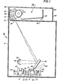
- Figure 1 is a side view in cross section showing the micro scanner of the present invention;
- Figure 2 is a top view in cross section of the scanner shown in Figure 1;
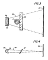
- Figure 3 is a view in the horizontal plane showing the scanning beam It unfolded;
- Figure 4 is a view in the vertical plane showing the scanning beam unfolded;
- Figure 5 is an enlarged isometric view showing details of the search light-like scanning mechanism for the scanner shown in Figure 1;
- Figure 6 is a logic schematic of the operating control system for the scanner shown in Figure 1;
- Figure 7 is a side view in cross section showing an alternative micro scanner design; and
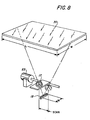
- Figure 8 is an isometric view showing an exemplary dimensional relationship between certain of the component parts of the scanner to provide micro-like scan movement of the scanner lens.
- Referring particularly to Figure 1 of the drawings, there is shown the
micro scanner apparatus 10 of the present invention. As will appear,scanner 10 is operable in either a stationary document or moving document scan mode to scan a document original 8 line by line to convert the document image to electrical signals or pixels.Scanner 10 includes asuitable frame 12 having a substantiallyflat base portion 13 on which one or morelinear arrays 15 are suitably supported in fixed position.Arrays 15 may comprise any suitable scanning array such as a charge coupled device (C.C.D.). One suitable array is model No. 1728 C.C.D. manufactured by Fairchild Corporation. - As will be understood by those skilled in the art, more than one
array 15 may be used, it being understood that additional arrays serve to increase image resolution. In the eventseveral arrays 15 are used, the array viewing fields may be abutted or overlapped, either electronically or optically to prevent any gaps in the viewing field of thescanning apparatus 10. Asuitable clock 16 is provided for operating thearray 15 in a manner understood by those skilled in the art. - A
suitable reduction lens 17 is supported abovearray 15 and in relatively close proximity thereto,lens 17 serving to focus the image rays reflected from thedocument 8 being scanned onto thearray 15. As best seen in Figures 1 and 5,lens 17 is mounted in a block like structure, identified aslens block 19 herein, which in turn is fixedly attached to and supported by thearmature shaft 22 of alinear type motor 23.Motor 23 is supported in stationary position onbase 13 by means ofrigid support members 25 such that the axis ofshaft 22 is substantially parallel tobase 13. Abearing block 27 provides further support forarmature shaft 22,block 27 being secured tobase 13 offrame 12. Suitable journal or bearing means (not shown) inblock 27 permit reciprocating movement ofarmature shaft 22 in the left-right direction as seen in Figure 1. -
Linear motor 23 may comprise any suitable linear actuator, i.e. a voice coil, hydraulic cylinder, etc. Stops 29, 29' onarmature shaft 22 cooperate with the motor housing andblock 27 to limit reciprocating movement ofarmature shaft 22 and the scanning movement oflens 17 mounted thereon. As will appear, the scanning movement or stroke oflens 17 is relatively small. - A substantially
planar platen 30 for supportingdocuments 8 to be scanned is mounted onframe 12 in preset spaced relationship tolens 17 and thescanning array 15.Platen 30, which is formed from any suitable transparent material such as glass serves in thescanning apparatus 10 as a support for both stationary and movingdocuments 8 as will appear. A slit-like scanning aperture 32 is provided inplaten 30 adjacent one end thereof,aperture 32 extending in the cross scan direction across the width (W) ofplaten 30. As will be understood, the length (L) and width (W) dimensions ofplaten 30 and the width ofscanning aperture 32 are sufficient to accommodate thelargest size document 8 to be scanned. - To illuminate the
document 8 to be scanned, ahigh intensity lamp 36 is provided,lamp 36 being suitably supported bymember 26 onbase 12. Anelliptical reflector 38 cooperates withlamp 36 to direct a sheet or wedge-like beam 35 of light onto an oscillatingsweep mirror 42 disposed in preset spaced relationship to thelamp mirror combination mirror 42 serving to reflect thelight beam 35 ontoplaten 30. As best seen in Figures 3 and 4, thebeam 35 of light emitted bylamp 36 and scanned acrossplaten 30 bysweep mirror 42 diverges when viewed in the horizontal plane while when viewed in thevertical plane beam 35 converges atplaten 30, the relative operating parameters and locations of the various components being chosen to assure a scanning beam whose width in the cross scan direction is at least equal to the width of the largest document to be scanned and whose thickness in the scan direction is at least equal to that of an image scanline. And whilereflector 38 is shown as being elliptical in shape, other configurations such as parabolic may be envisioned. - For operation in the stationary document scan mode,
mirror 42 is supported by an upwardly projectingarm pair 43 mounted for pivotal movement as bypins 44 on the extremities oflens block 19. In the embodiment shown, the axis of rotation ofmirror 42 aboutpins 44 intersects the optical axis oflens 17. To impart the required oscillating movement tomirror 42,arms 43 are provided with suitably configuredcam tracks 48,cam tracks 48 being engageable withcam element 49 mounted oncam support members 50.Cam support members 50 are in turn fixed tobase 13 offrame 12. Accordingly, asarmature shaft 22 reciprocates back and forth to movelens 17, engagement ofcam tracks 48 withcam element 49 causemirror 42 to swing in a predetermined arc about the axis ofpins 44 to sweep the beam of light emitted bylamp 36 acrossplaten 30 in searchlight fashion. The scanning movement or stroke oflight beam 35 is as will appear sufficient to scan the length (L) of thelargest document 8 to be scanned and is substantially greater than the distance through whichlens 17 is moved. - For operation in the moving document scan mode, a
document transport 55 is provided.Document transport 55 includes a constant velocity transport (C.V.T. herein) roll 57 for moving a document acrossscanning aperture 32 at a predetermined scanning rate. C.V.T.roll 57 is suitably journaled for rotation in the document handler housing_58._Roll 57 is drivingly coupled to ascan motor 60 as bybelt 61. A pair ofarcuate return guides pinch roll pairs 65 to guide the document discharged byroll 57 to documentreturn roll 67 and adocument catch tray 68.Document return roll 67, which is rotatably journaled inhousing 58, andpinch roll pair 65 may be driven in the direction shown by the solid line arrows by a suitable drive motor such asscan motor 60. To maintainrolls tray 68, a suitable timing control (not shown) may be provided for the roll driving motor. When operating in the moving document scan mode, the document to be scanned is inserted manually into the nip formed byCVT roll 57 andplaten 30 at the start of scanner operation, opening 58' being provided inhousing 58 for this purpose. - In this operational mode,
lens 17 andsweep mirror 42 are parked in a predetermined position such thatscanning aperture 32 is illuminated and 4 focused onarray 15, the park position being established through interengagement of motor shaft stop 29' withframe member 27. - Where operation in the moving document mode is desired,
selector 80 is set to the dotted line position shown in Figure 6. In this position,clock 16 andlamp 36 are readied for energization whilelinear motor 23 is held in a disabled state to maintainlens 17 andmirror 42 in the park or stationary position shown by the solid lines of Figure 1. Additionally, scanmotor 60 is readied for energization. - The document to be scanned is inserted into the nip formed by
CVT roll 57 andplaten 30 and, on a demand for image signals,clock 16,lamp 36, and scanmotor 60 are energized. Energization ofmotor 60 operatesCVT roll 57 to advance the document across scanningaperture 32 where the document is scanned line by line byarray 15,pinch roll pair 65 and returnroll 67 cooperating with document guides 63, 64 to transport the scanned document to catchtray 68. - Referring to Figure 6, a
suitable mode selector 80 is provided to permit the operator or user to select the operating mode ofscanning apparatus 10, i.e. either the stationary or moving document scan mode. Where operation in the stationary document scan mode is desired, the document to be scanned may be manually placed onplaten 30 andselector 80 set to the solid line position shown readyingclock 16,linear motor 23, andlamp 36 for energization. On a demand for image signals, the signal inline 81 energizesclock 16,lamp 36 andlinear motor 23, thelatter moving lens 17 together withmirror 42 through a preset path at a predetermined scan rate. The swinging motion imparted to mirror 42 sweeps the beam of light output bylamp 36 across theplaten 30 and thedocument 8 thereon to illuminate the document line by line. The image rays reflected fromdocument 8 as the beam of light sweeps thereacross are focused ontoarray 15 bylens 17, movement oflens 17 serving to maintain focus as the moving beam of light scans acrossplaten 30. - In the embodiment shown in Figure 7, where like numbers refer to like parts, a moving
illumination cavity 85 is used in place of the searchlight mirror system shown in the Figures 1-6 embodiment.Illumination cavity 85 includes an elongated generallyU-shaped reflector cavity 87 within which are disposed one or more high intensity lamps 88. Thebase portion 89 ofcavity 87 has an elongated scanning aperture 90 formed therein to permit image rays reflected from the document being scanned to pass therethrough tolens 17 and thearray 15. -
Illumination cavity 85 is supported for reciprocating movement in predetermined spaced relationship with and belowplaten 30 as by means of cooperating track and pin means 82, 83 on either side thereof. A suitable driving mechanism such asmotor 95 is provided for movingillumination cavity 85 back and forth belowplaten 30. - Operation of the Figure 7 embodiment is generally similar to that described heretofore in connection with the Figures 1-6 embodiment with the
illumination cavity 85 being moved bymotor 95 in synchronism with movement oflens 17 during operation in the stationary document scan mode. On completion of the scan cycle,motor 95returns cavity 85 to the start of scan position shown. In the moving document scan mode,illumination cavity 85 is parked in a position oppositeplaten scanning aperture 32 while the document to be scanned is moved acrossplaten 30 bydocument transport 55. - Referring particularly to Figure 8 where like numbers refer to like parts, in one example, it was desired that
scanner 10 be able to accommodate document sizes up to 36.4cm in width (W) by 43.2cm in length (L) using alinear array 15 having a width (W) of 2.865cm. A reduction of 12.7:1 was chosen in order to focus document lines up to the aforesaid 36.4cm onto thearray 15 while keeping movement oflens 17 to a minimum. In that example,sweep mirror 42scans beam 35 through a distance of 43.2cm to accommodate the length (L) of the maximum size document whilelens 17 is moved in synchronism withbeam 35 through a distance of only 3.40cm bylinear motor 23. This achieves the desired reduction ratio of 12.7:1, and permitsscanner 10 to handle relatively large size documents while keeping movement oflens 17 to a minimum. - In another example, a reduction of 13.229:1 was provided to accommodate document sizes up to 36.4cm in width (W) by 25.70cm in length (L) using a
linear scanning array 15 having a width of 2.745cm. In this example,lens 17 is moved through a distance of 2.11cm whilebeam 35 is scanned through a distance of 25.70cm. - It is understood that. the above are examples only and other dimensional relationships and reduction ratios may be contemplated in the light of the present invention.
- It will be understood that whereas
platen 30 together withdocument transport 55 is shown in a position above scanning system 14, other positional relationships i.e. where the respective positions ofplaten 30,ADH 55 and scanning system 14 are reversed, may be contemplated.
Claims (9)
Applications Claiming Priority (2)
| Application Number | Priority Date | Filing Date | Title |
|---|---|---|---|
| US06/364,132 US4409624A (en) | 1982-03-31 | 1982-03-31 | Raster scanning apparatus |
| US364132 | 1982-03-31 |
Publications (2)
| Publication Number | Publication Date |
|---|---|
| EP0091280A1 true EP0091280A1 (en) | 1983-10-12 |
| EP0091280B1 EP0091280B1 (en) | 1986-03-05 |
Family
ID=23433155
Family Applications (1)
| Application Number | Title | Priority Date | Filing Date |
|---|---|---|---|
| EP83301814A Expired EP0091280B1 (en) | 1982-03-31 | 1983-03-30 | Raster scanning apparatus |
Country Status (5)
| Country | Link |
|---|---|
| US (1) | US4409624A (en) |
| EP (1) | EP0091280B1 (en) |
| JP (1) | JPS58184872A (en) |
| CA (1) | CA1198150A (en) |
| DE (1) | DE3362376D1 (en) |
Families Citing this family (12)
| Publication number | Priority date | Publication date | Assignee | Title |
|---|---|---|---|---|
| US4866536A (en) * | 1983-10-26 | 1989-09-12 | Canon Kabushiki Kaisha | Image recording apparatus |
| JPS6091760A (en) * | 1983-10-26 | 1985-05-23 | Canon Inc | Picture recording device |
| JPS60117866A (en) * | 1983-11-29 | 1985-06-25 | Toshiba Corp | Picture information reader |
| US5191406A (en) * | 1990-04-20 | 1993-03-02 | Nikon Corporation | Method and apparatus for rapid scanning of color images |
| JPH05182873A (en) * | 1991-12-27 | 1993-07-23 | Rohm Co Ltd | Manufacture of solid electrolytic capacitor and solid electrolytic capacitor manufactured thereby |
| US5821981A (en) * | 1996-07-02 | 1998-10-13 | Gerber Systems Corporation | Magnetically preloaded air bearing motion system for an imaging device |
| US5841567A (en) * | 1996-07-02 | 1998-11-24 | Barco Gerber Systems | Method and apparatus for imaging at a plurality of wavelengths |
| US5828501A (en) * | 1996-07-02 | 1998-10-27 | Barco Gerber Systems | Apparatus and method for positioning a lens to expand an optical beam of an imaging system |
| US5831757A (en) * | 1996-09-12 | 1998-11-03 | Pixar | Multiple cylinder deflection system |
| US5938187A (en) * | 1997-04-18 | 1999-08-17 | Gerber Systems Corporation | Media feed apparatus for an imaging device |
| US5912458A (en) * | 1997-04-18 | 1999-06-15 | Gerber Systems Corporation | Multiple beam scanning system for an imaging device |
| US6042101A (en) * | 1997-06-03 | 2000-03-28 | Gerber Systems Corporation | Automated media transport device and method of using the same |
Citations (4)
| Publication number | Priority date | Publication date | Assignee | Title |
|---|---|---|---|---|
| US3419327A (en) * | 1965-07-09 | 1968-12-31 | Hitachi Ltd | Xerographic reproducing apparatus |
| CH580896A5 (en) * | 1973-06-01 | 1976-10-15 | Taplin Business Machines | |
| US4150873A (en) * | 1977-07-29 | 1979-04-24 | Eastman Kodak Company | Bi-directional optical scanning |
| US4266252A (en) * | 1979-09-12 | 1981-05-05 | The Mead Corporation | Lens system for document scanning |
Family Cites Families (5)
| Publication number | Priority date | Publication date | Assignee | Title |
|---|---|---|---|---|
| US4149091A (en) * | 1977-05-02 | 1979-04-10 | Xerox Corporation | Scanning apparatus |
| JPS5560732A (en) * | 1978-10-27 | 1980-05-08 | Mitsubishi Electric Corp | Electromagnetic coupling device rotatable in both directions |
| JPS5560372A (en) * | 1978-10-30 | 1980-05-07 | Ricoh Co Ltd | Picture part reader |
| US4256959A (en) * | 1979-09-12 | 1981-03-17 | The Mead Corporation | Optical scanner including feedback for reflector control |
| US4321627A (en) * | 1979-09-20 | 1982-03-23 | International Business Machines Corporation | Optical scanner for ink jet printer |
-
1982
- 1982-03-31 US US06/364,132 patent/US4409624A/en not_active Expired - Fee Related
-
1983
- 1983-03-23 CA CA000424230A patent/CA1198150A/en not_active Expired
- 1983-03-24 JP JP58049669A patent/JPS58184872A/en active Granted
- 1983-03-30 DE DE8383301814T patent/DE3362376D1/en not_active Expired
- 1983-03-30 EP EP83301814A patent/EP0091280B1/en not_active Expired
Patent Citations (4)
| Publication number | Priority date | Publication date | Assignee | Title |
|---|---|---|---|---|
| US3419327A (en) * | 1965-07-09 | 1968-12-31 | Hitachi Ltd | Xerographic reproducing apparatus |
| CH580896A5 (en) * | 1973-06-01 | 1976-10-15 | Taplin Business Machines | |
| US4150873A (en) * | 1977-07-29 | 1979-04-24 | Eastman Kodak Company | Bi-directional optical scanning |
| US4266252A (en) * | 1979-09-12 | 1981-05-05 | The Mead Corporation | Lens system for document scanning |
Also Published As
| Publication number | Publication date |
|---|---|
| JPS58184872A (en) | 1983-10-28 |
| DE3362376D1 (en) | 1986-04-10 |
| US4409624A (en) | 1983-10-11 |
| CA1198150A (en) | 1985-12-17 |
| EP0091280B1 (en) | 1986-03-05 |
| JPH0550186B2 (en) | 1993-07-28 |
Similar Documents
| Publication | Publication Date | Title |
|---|---|---|
| US7446909B2 (en) | Image reader for use in image forming apparatus | |
| EP0751665A2 (en) | Method and apparatus for positioning a focusing lens | |
| EP0091280B1 (en) | Raster scanning apparatus | |
| JP3376030B2 (en) | Image reading device | |
| US4982236A (en) | Self supporting optical document scanning system | |
| US5012275A (en) | Right-to-left scanning system for copying documents or bound books | |
| US6421158B1 (en) | Optical scanning module with rotatable reflection mirror for image scanning device | |
| EP0751664B1 (en) | Apparatus for alignment of material to be scanned in a flat-bed scanner | |
| US5218200A (en) | Image scanner with turnable reflecting plate for scanning objects at different locations | |
| US20030063336A1 (en) | Image scanning apparatus with cross-shaped document passage | |
| GB1597569A (en) | Photocopier scanning illumination system | |
| EP0751666A2 (en) | Scanner encoder system | |
| US5959745A (en) | Transmission mechanism for an image information reading apparatus | |
| US4666287A (en) | Document copiers | |
| US6728010B1 (en) | Color image reader for use in image forming apparatus | |
| JPS62291259A (en) | Reader | |
| US5693937A (en) | Image information reading apparatus with an internal document tray | |
| JP2791713B2 (en) | Image reading device | |
| JPH07135553A (en) | Picture reader | |
| JP3445892B2 (en) | Document reading device | |
| JP3017775B2 (en) | Image reading device | |
| JP2001245108A (en) | Image reader and image processor | |
| JPH01195756A (en) | Reader | |
| JPS6122332A (en) | Image recording device | |
| JPH1195332A (en) | Image reader |
Legal Events
| Date | Code | Title | Description |
|---|---|---|---|
| PUAI | Public reference made under article 153(3) epc to a published international application that has entered the european phase |
Free format text: ORIGINAL CODE: 0009012 |
|
| AK | Designated contracting states |
Designated state(s): DE GB |
|
| 17P | Request for examination filed |
Effective date: 19840319 |
|
| GRAA | (expected) grant |
Free format text: ORIGINAL CODE: 0009210 |
|
| AK | Designated contracting states |
Kind code of ref document: B1 Designated state(s): DE GB |
|
| REF | Corresponds to: |
Ref document number: 3362376 Country of ref document: DE Date of ref document: 19860410 |
|
| PLBE | No opposition filed within time limit |
Free format text: ORIGINAL CODE: 0009261 |
|
| STAA | Information on the status of an ep patent application or granted ep patent |
Free format text: STATUS: NO OPPOSITION FILED WITHIN TIME LIMIT |
|
| 26N | No opposition filed | ||
| PGFP | Annual fee paid to national office [announced via postgrant information from national office to epo] |
Ref country code: GB Payment date: 19950321 Year of fee payment: 13 |
|
| PGFP | Annual fee paid to national office [announced via postgrant information from national office to epo] |
Ref country code: DE Payment date: 19950322 Year of fee payment: 13 |
|
| PG25 | Lapsed in a contracting state [announced via postgrant information from national office to epo] |
Ref country code: GB Effective date: 19960330 |
|
| GBPC | Gb: european patent ceased through non-payment of renewal fee |
Effective date: 19960330 |
|
| PG25 | Lapsed in a contracting state [announced via postgrant information from national office to epo] |
Ref country code: DE Effective date: 19961203 |