EP0092015A1 - Ionizing device - Google Patents
Ionizing device Download PDFInfo
- Publication number
- EP0092015A1 EP0092015A1 EP82810160A EP82810160A EP0092015A1 EP 0092015 A1 EP0092015 A1 EP 0092015A1 EP 82810160 A EP82810160 A EP 82810160A EP 82810160 A EP82810160 A EP 82810160A EP 0092015 A1 EP0092015 A1 EP 0092015A1
- Authority
- EP
- European Patent Office
- Prior art keywords
- electrodes
- current
- transistor
- generator
- pair
- Prior art date
- Legal status (The legal status is an assumption and is not a legal conclusion. Google has not performed a legal analysis and makes no representation as to the accuracy of the status listed.)
- Withdrawn
Links
Images
Classifications
-
- A—HUMAN NECESSITIES
- A61—MEDICAL OR VETERINARY SCIENCE; HYGIENE
- A61N—ELECTROTHERAPY; MAGNETOTHERAPY; RADIATION THERAPY; ULTRASOUND THERAPY
- A61N1/00—Electrotherapy; Circuits therefor
- A61N1/18—Applying electric currents by contact electrodes
- A61N1/20—Applying electric currents by contact electrodes continuous direct currents
- A61N1/30—Apparatus for iontophoresis, i.e. transfer of media in ionic state by an electromotoric force into the body, or cataphoresis
Definitions
- the present invention relates to an ionization device comprising at least one adjustable current generator and at least one pair of electrodes detachably connected to said generator by connection means.
- This ionization consists in passing a direct current of low intensity between two parts of the patient's body, which causes electrolysis facilitating the penetration of the treatment solution.
- the devices used for this purpose comprise several pairs of plug-in electrodes each connected to an adjustable current generator. These generators are isolated from each other and generally include a milliammeter allowing the current in the corresponding probe to be measured.
- the object of the present invention is to remedy the disadvantages mentioned above, that is to say to produce an ionization device practically and automatically eliminating any risk of burns due to handling errors.
- the device further comprises means connected to said generator for determining the intensity of the current delivered by said generator to said electrodes, said means depending on the type of pair of electrodes connected to said generator.
- the current of the latter can be determined automatically so as to eliminate any risk of burns to the patient.
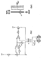
- the current generator of fig. 1 is formed by an adjustable voltage divider formed by a resistor 1 connected to the positive pole of the power supply and a potentiometer 2 connected to the negative pole of the power supply (ground).
- the potentiometer cursor is connected to the direct input (+) of an operational amplifier 3, the output of which is connected by a resistor 4 to its inverting input (-), itself connected to ground by a resistor 5.
- This well-known configuration makes it possible to obtain at the output of the amplifier a voltage proportional to the voltage EU on its direct input according to the relationship
- the voltage Us is applied to the direct input of a second operational amplifier 6, the output of which is connected by a resistor 7 to the base of a transistor 8 connected to a common collector, this transistor acting as a power amplifier.
- the emitter of transistor 8 is connected to terminal 9a of a three-pole connector 9, terminal 9b of which is connected to the inverting input of amplifier 6, and terminal 9c of which is connected to ground.
- the connector 9 makes it possible to connect the generator to a pair of electrodes 10a and 10b.
- the electrodes of a pair are generally of the same surface, but they can be of different surfaces depending on the parts of the patient's body to which they are applied.
- the smaller surface electrode is then decisive for the density of the current delivered between the electrodes.
- They generally include a wire mesh mounted on rubber and covered with a cloth or sponge.
- Each electrode is connected by a flexible conductor to a terminal of a suitable plug.
- this plug includes at least a third terminal c to which an adjustment element is connected, in this case a resistor 11 connected moreover to the electrode 10a.
- This resistor can be mounted directly in the plug or ecore on the electrode 10a, but in all cases it must remain integral with the pair of electrodes, the electrode-resistance assembly forming a whole.
- the voltage at the input which reverses from the amplifier 6 is maintained at the same value as the voltage on its direct input, this provided that a sufficient current can pass between the electrodes 10a and 10b. This is the case when the electrodes have been correctly placed on the patient.
- the value of the current Ie in the electrodes is then determined by the voltage between the input which inverts se of the amplifier 6 and the mass, according to the relation:
- the value of the current therefore depends on the one hand on the position ⁇ of the potentiometer cursor, which is obvious, but also on the resistance R11.
- the current per unit area that is to say the current density
- the current per unit area becomes independent of the type of the pair of electrodes used and that it does not depends more than on the position ⁇ of the potentiometer.
- R11 1 kiloohm, which allows a maximum current of 2.5 mA always corresponding to a current density of 0.1 m A / cm 2 .
- this instrument is replaced by a light emitting diode (LED) 14 whose light intensity varies in proportion to the current density.
- LED light emitting diode
- the input which reverses from the amplifier 6 is connected to the direct input of an operational amplifier 13 with a counter circuit. reaction formed by an LED 14 and a resistor 15.
- the current in the diode 14 is equal to Us / R15, that is to say to ⁇ ⁇ Usmax / R15, intensity proportional to the position of the cursor of the potentiometer 2, at least under normal operating conditions.
- One of the first anomalies that can occur is too high resistance to the flow of current through the electrodes. This excessively high resistance may be due to the fact that the electrodes are incorrectly positioned and that they are partially detached, which produces a reduction in the effective current flow area and a local overcurrent. It is therefore necessary to limit the voltage across the electrodes. This voltage Ue is proportional to the resistance Re between electrodes:
- the emitter of transistor 8 is connected to the direct input of a voltage comparator 18, the inverting input of which is connected to a voltage divider formed by resistors 16 and 17 delivering on this input which inverts a reference voltage slightly lower than the supply voltage.
- a safety circuit comprising a voltage comparator 21 whose inverting input is connected to the inverting input of the amplifier 6 and by the terminal 9b of the connector 9 to the resistor 11, l 'direct input of this comparator 21 being connected to the input which inverts the amplifier 3.
- the voltage on this input is determined by the voltage divider formed by resistors R4 and R5 according to the relation: When the voltage across R11 falls below this value, the output of comparator 21 changes to + V. A current then flows through a light-emitting diode 22 (LED) signaling "safety”, then through an optocoupler 23 in the base of a transistor 24 whose emitter is grounded and whose collector is connected to the base of transistor 8.
- LED light-emitting diode 22
- This transistor 24 therefore becomes conductive and it short-circuits the base of transistor 8 against ground.
- the transistor 8 becomes non-conductive and it no longer passes any current through the electrodes.
- the power supply is interrupted.
- the outputs of the optocoupler 23 can also be connected to the inputs of a siren 30 which delivers an acoustic signal in order to warn the operator if the latter is not close to the device when security is triggered.
- a low value resistor 26 is connected in series in the electrode supply circuit. This resistor 26 is connected to the two terminals of a connector 27, a connector to which a digital or analog measuring instrument 28 can be connected.
- Ionization devices always include several pairs of electrodes and several current generators, it is thus possible to successively check the current in each pair of electrodes by means of a single measuring instrument by plugging it into the connectors provided for this purpose.
- Figure 3 shows an example of possible arrangement of the elements 2, 14, 19 and 22, allowing rapid control of the proper functioning of the device.
- a linear potentiometer associated with a graduation in mA / cm 2 allows precise dosing of the current for all types of electrode pairs used.
Abstract
Description
La présente invention concerne un dispositif d'ionisation comportant au moins un générateur de courant réglable et au moins une paire d'électrodes branchées de manière amovible audit générateur par des moyens de connexion.The present invention relates to an ionization device comprising at least one adjustable current generator and at least one pair of electrodes detachably connected to said generator by connection means.
Il devient de plus en plus fréquent, pour certains traitements dans le domaine de l'esthétique ou de la rhumatologie, d'utiliser le procédé d'ionisation. Cette ionisation consiste à faire passer un courant continu de faible intensité entre deux parties du corps du patient, ce qui provoque une électrolyse facilitant la pénétration de la solution de traitement. Les appareils utilisés à cet effet comportent plusieurs paires d'électrodes enfichables reliées chacune à un générateur de courant réglable. Ces générateurs sont isolés entre eux et comportent généralement un milliampèremètre permettant de mesurer le courant dans la sonde correspondante.It is becoming more and more frequent, for certain treatments in the field of aesthetics or rheumatology, to use the ionization process. This ionization consists in passing a direct current of low intensity between two parts of the patient's body, which causes electrolysis facilitating the penetration of the treatment solution. The devices used for this purpose comprise several pairs of plug-in electrodes each connected to an adjustable current generator. These generators are isolated from each other and generally include a milliammeter allowing the current in the corresponding probe to be measured.
Il est en effet de la plus grande importance de doser avec exactitude ce courant si l'on veut éviter les risques de brûlures, brûlures d'autant plus dangereuses qu'elles peuvent être indolores au moment de leur formation. Or, l'intensité du courant de consigne varie d'une paire d'électrodes à l'autre car, comme pour toute électrolyse, c'est l'intensité de courant par unité de surface qui importe, et l'on doit donc tenir compte des dimensions de ces électrodes. Pour cela, on utilise généralement une table de conversion, mais certains fabricants graduent directement les instruments en mA/cm2, ce qui nécessite plusieurs échelles correspondant chacune à un type d'électrodes de surface déterminée. Ces moyens sont limitatifs et il n'excluent en aucun cas les erreurs de manipulation, erreurs qui peuvent avoir des conséquences fâcheuses pour le patient.It is indeed of the greatest importance to measure this current accurately if we want to avoid the risk of burns, burns all the more dangerous as they can be painless at the time of their formation. However, the intensity of the setpoint current varies from one pair of electrodes to another because, as with all electrolysis, it is the current intensity per unit of sur face that matters, and we must therefore take into account the dimensions of these electrodes. For this, a conversion table is generally used, but certain manufacturers directly scale the instruments in mA / cm 2 , which requires several scales each corresponding to a type of electrodes with a determined surface. These means are limiting and in no way exclude handling errors, errors which can have unfortunate consequences for the patient.
Le but de la présente invention est de remédier aux désavantages mentionnés ci-dessus, c'est-à-dire de réaliser un dispositif d'ionisation supprimant pratiquement et automatiquement tout risque de brûlures dû à des erreurs de manipulation.The object of the present invention is to remedy the disadvantages mentioned above, that is to say to produce an ionization device practically and automatically eliminating any risk of burns due to handling errors.
Pour atteindre ce but, le dispositif selon l'invention comprend en outre des moyens reliés audit générateur pour déterminer l'intensité du courant délivré par ledit générateur auxdites électrodes, lesdits moyens dépendant du type de la paire d'électrodes branchée audit générateur.To achieve this object, the device according to the invention further comprises means connected to said generator for determining the intensity of the current delivered by said generator to said electrodes, said means depending on the type of pair of electrodes connected to said generator.
Par le fait que les moyens dépendent de la paire d'électrodes connectée au générateur, le courant de ce dernier, et plus précisément la densité de courant entre les électrodes, peut être déterminé automatiquement de manière à éliminer tout risque de brûlures du patient.By the fact that the means depend on the pair of electrodes connected to the generator, the current of the latter, and more precisely the current density between the electrodes, can be determined automatically so as to eliminate any risk of burns to the patient.
L'invention va être décrite ci-après, à titre d'exemple et à l'aide du dessins dans lequel:
- La fig. 1 représente schématiquement le circuit du dispositif selon l'invention, comportant un générateur de courant simplifié,
- La fig. 2 représente le circuit de la fig. 1 complété par des moyens de sécurité et de contrôle, et
- La fig. 3 représente un exemple de graduation et de disposition des éléments de contrôle et de réglage.
- Fig. 1 diagrammatically represents the circuit of the device according to the invention, comprising a simplified current generator,
- Fig. 2 shows the circuit of FIG. 1 completed by security and control means, and
- Fig. 3 shows an example of graduation and arrangement of the control and adjustment elements.
Le générateur de courant de la fig. 1 est formé d'un diviseur de tension réglable formé d'une résistance 1 reliée au pôle positif de l'alimentation et d'un potentiomètre 2 relié au pôle négatif de l'alimentation (masse). Le curseur du potentiomètre est relié à l'entrée directe (+) d'un amplificateur opérationnel 3 dont la sortie est reliée par une résistance 4 à son entrée qui inverse (-), elle-même reliée à la masse par une résistance 5. Cette configuration bien connue permet d'obtenir à la sortie de l'amplificateur une tension proportionelle à la tension UE sur son entrée directe selon la relation
La tension UE dépend de la position du potentiomètre et varie de 0 à UEmax, de sorte que Us varie de 0 à Usmax. Si le potentiomètre est linéaire, la tension de sortie est donnée par Us = Usmax · α où α représente la position du curseur du potentiomètre par rapport à la course totale.The voltage UE depends on the position of the potentiometer and varies from 0 to UEmax, so that Us varies from 0 to Usmax. If the potentiometer is linear, the output voltage is given by Us = Usmax · α where α represents the position of the potentiometer cursor relative to the total stroke.
La tension Us est appliquée à l'entrée directe d'un deuxième amplificateur opérationnel 6 dont la sortie est reliée par une résistance 7 à la base d'un transistor 8 branché en collecteur commun, ce transistor faisant office d'amplificateur de puissance.The voltage Us is applied to the direct input of a second operational amplifier 6, the output of which is connected by a resistor 7 to the base of a
L'émetteur du transistor 8 est relié à la borne 9a d'un connecteur 9 à trois pôles dont la borne 9b est reliée à l'entrée qui inverse de l'amplificteur 6, et dont la borne 9c est connectée à la masse. Le connecteur 9 permet de relier le générateur à une paire d'électrodes 10a et 10b.The emitter of
Les électrodes d'une paire sont généralement de même surface, mais elles peuvent être de surfaces différentes selon les parties du corps du patient auxquelles elles sont appliquées. L'électrode de plus petite surface est alors déterminante pour la densité du courant délivré entre les électrodes. Elles comportent généralement un treillis métallique monté sur caoutchouc et recouvert d'un tissu ou d'une éponge. Chaque électrode est reliée par un conducteur souple à une borne d'une fiche adéquate.The electrodes of a pair are generally of the same surface, but they can be of different surfaces depending on the parts of the patient's body to which they are applied. The smaller surface electrode is then decisive for the density of the current delivered between the electrodes. They generally include a wire mesh mounted on rubber and covered with a cloth or sponge. Each electrode is connected by a flexible conductor to a terminal of a suitable plug.
Dans le dispositif selon l'invention, cette fiche comporte au moins une troisième borne c à laquelle est branché un élément de réglage, en l'occurence une résistance 11 reliée par ailleurs à l'électrode 10a. Cette résistance peut être montée directement dans la fiche ou ecore sur l'électrode 10a, mais dans tous les cas elle doit rester solidaire de la paire d'électrodes, l'ensemble électrodes-résistance formant un tout.In the device according to the invention, this plug includes at least a third terminal c to which an adjustment element is connected, in this case a resistor 11 connected moreover to the electrode 10a. This resistor can be mounted directly in the plug or ecore on the electrode 10a, but in all cases it must remain integral with the pair of electrodes, the electrode-resistance assembly forming a whole.
Voyons ce qui se passe lorsque la paire d'électrodes est branchée, c'est-à-dire lorsque la fiche est en place sur le connecteur 9. La paire d'électrodes 10 est alors branchée en contre-réaction par la résistance 7, le transistor 8, la borne 9a et la borne 9b entre la sortie et l'entrée qui inverse de l'amplificateur 6, alors que la résistance 11 est reliée par les bornes 9b et 9c entre l'entrée qui inverse de l'amplificateur 6 et la masse.Let’s see what happens when the pair of electrodes is connected, that is to say when the plug is in place on the connector 9. The pair of
Dans cette configuratin bien connue, la tension à l'entrée qui inverse de l'amplificateur 6 est maintenue à la même valeur que la tension sur son entrée directe, ceci pour autant qu'un courant suffisant puisse passer entre les électrodes 10a et 10b. C'est le cas lorsque les électrodes ont été mises correctement en place sur le patient. La valeur du courant Ie dans les électrodes est alors déterminée par la tension entre l'entrée qui inverse de l'amplificateur 6 et la masse, selon la relation:
La valeur du courant dépend donc d'une part de la position α du curseur du potentiomètre, ce qui est évident, mais également de la résistance R11. La valeur de cette dernière est choisie en fonction de la surface des électrodes:
le courant devient alors égal à

On voit donc que par un choix adéquat de la valeur de la résistance 11, le courant par unité de surface, c'est-à-dire la densité de courant devient indépendant du type de la paire d'électrodes utilisée et qu'il ne dépend plus que de la position α du potentiomètre. Ainsi, pour des paires d'électrodes ayant entre elles un rapport de 10 en surface (surface des plus petites électrodes de chaque paire), on aura un rapport de 10 entre les valeurs des résistances R11 associées et aussi entre les intensités de courant, mais on aura une densité de courant uniforme.It can therefore be seen that by an adequate choice of the value of the resistance 11, the current per unit area, that is to say the current density, becomes independent of the type of the pair of electrodes used and that it does not depends more than on the position α of the potentiometer. Thus, for pairs of electrodes having a surface ratio of 10 between them (surface of the smallest electrodes of each pair), there will be a ratio of 10 between the values of the associated resistances R11 and also between the current intensities, but we will have a neck density uniform rant.
Par exemple, pour une électrode de 250 cm2, on choisit Usmax = 2,5V et R11 = 100 ohm, ce qui permet de régler le courant à une valeur maximum de 25 mA correspondant à une densité de courant de 0,1 mA/cm 2.For example, for an electrode of 250 cm 2 , we choose Usmax = 2.5V and R11 = 100 ohm, which allows the current to be set to a maximum value of 25 mA corresponding to a current density of 0.1 mA / cm 2.
Par contre pour une électrode de 25cm2 et Usmax de 2,5V, on choisit R11 égal à 1 kiloohm, ce qui permet un courant maximum de 2,5 mA correspondant toujours à une densité de courant de 0,1 mA/cm2.By cons for an electrode of 25cm 2 and Usmax of 2.5V, we choose R11 equal to 1 kiloohm, which allows a maximum current of 2.5 mA always corresponding to a current density of 0.1 m A / cm 2 .
On a ainsi une adaption automatique de l'intensité du courant à la surface des électrodes utilisées, ce qui permet d'éviter tout risque de surintensité et de brûlure.There is thus an automatic adaptation of the intensity of the current at the surface of the electrodes used, which avoids any risk of overcurrent and burns.
Il est possible de vérifier cette densité de courant au moyen d'un instrument 12 gradué en mA/cm2. Toutefois, il est également possible de graduer directement le potentiomètre puisque la densité de courant dépend directement de la position de son curseur, du moins lorsque le fonctionnement du dispositif est normal.It is possible to check this current density using an
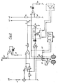
Cependant, il peut se produire certaines anomalies qu'il est souhaitable de signaler, ce qui est prévu dans le schéma de la figure 2. On retrouve dans ce schéma le générateur formé des éléments 1 à 8, le connecteur 9, la paire d'électrodes 10 et la résistance 11. L'instrument 12 a été supprimé.However, some anomalies may occur which it is desirable to report, which is provided for in the diagram in Figure 2. We find in this diagram the generator formed of elements 1 to 8, the connector 9, the pair of
Comme le potentiomètre 2 est gradué, cet instrument est remplacé par une diode émettrice de lumière (LED) 14 dont l'intensité lumineuse varie proportionnellement à la densité de courant. A cet effet, l'entrée qui inverse de l'amplificateur 6 est reliée à l'entrée directe d'un amplificateur opérationnel 13 avec un circuit de contre-réaction formé d'une diode LED 14 et d'une résistance 15. Le courant dans la diode 14 est égal à Us/R15, c'est-à-dire à α·Usmax/R15, intensité proportionnelle à la position du curseur du potentiomètre 2, au moins dans les conditions normales de fonctionnement.As the potentiometer 2 is graduated, this instrument is replaced by a light emitting diode (LED) 14 whose light intensity varies in proportion to the current density. For this purpose, the input which reverses from the amplifier 6 is connected to the direct input of an
Une des premières anomalies qui peut se produire est une résistance trop élevée au passage du courant dans les électrodes. Cette résistance trop élevée peut être due au fait que les électrodes sont mal mises en place et qu'elles sont partiellement décollées, ce qui produit une diminution de la surface effective de passage du courant et une surintensité locale. Il est donc nécessaire de limiter la tension aux bornes des électrodes. Cette tension Ue est proportionnelle à la résistance Re entre électrodes:![]()
![]()
Lorsque la résistance Re augmente, la tension sur l'émetteur du transistor 8 augmente jusqu'au moment où elle s'approche de la tension d'alimentation. A ce moment, le système se sature et le courant dans les électrodes atteint une valeur limite qu'il ne peut plus dépasser. Par un choix judicieux entre la tension d'alimentation et la tension Usmax, on obtient donc une limitation automatique du courant dans les électrodes lorsque la résistance Re augmente de manière critique. Cette situation anormale doit toutefois être signalée. A cet effet, l'émetteur du transistor 8 est relié à l'entrée directe d'un comparateur de tension 18 dont l'entrée qui inverse est branchée à un diviseur de tension formé des résistances 16 et 17 délivrant sur cette entrée qui inverse une tension de référence légèrement inférieure à la tension d'alimentation.When the resistance Re increases, the voltage on the emitter of
Lorsque l'on s'approche de la saturation du système, la tension sur l'émetteur du transistor 8 dépasse la tension de référence et la sortie du comparateur 18 devient +V, rendant conductrice une diode émettrice de lumière (LED) 19 utilisée comme diode de signalisation, le courant dans cette diode étant limité par une résistance 20 branchée contre la masse.When we approach the saturation of the system, the voltage on the emitter of
On obtient ainsi une indication parfaitement claire d'une augmentation anormale de la résistance entre les électrodes, grâce à l'allumage de la diode 19 d'indication de saturation.This gives a perfectly clear indication of an abnormal increase in resistance between the electrodes, thanks to the lighting of the
Nous avons vu que lorsque le système est saturé, le courant Ie ne peut être maintenu à la valeur fixée. La valeur de la tension sur la résistance 11 devient donc inférieure à la tension Us de consigne.We have seen that when the system is saturated, the current Ie cannot be maintained at the fixed value. The value of the voltage on the resistor 11 therefore becomes lower than the set voltage Us.
Lorsque la saturation est faible, il n'y a pas lieu de s'alarmer et l'utilisateur peut se contenter de d'amener le potentiomètre 2 dans une position inférieure dans laquelle le système ne sature plus.When the saturation is low, there is no need to be alarmed and the user can simply bring the potentiometer 2 to a lower position in which the system no longer saturates.
Par contre, lorsque la saturation est très forte, c'est-à-dire lorsque la tension aux bornes de la résistance 11 devient très inférieure à la tension de consigne, il y a lieu d'interrompre immédiatement le circuit pour éviter tout risque de brûlure lors du traitement.On the other hand, when the saturation is very high, that is to say when the voltage across the resistor 11 becomes much lower than the set voltage, the circuit should be interrupted immediately to avoid any risk of burning during treatment.
Pour cela, on dispose d'un circuit de sécurité comportant un comparateur de tension 21 dont l'entrée qui inverse est reliée à l'entrée qui inverse de l'amplificateur 6 et par la borne 9b du connecteur 9 à la résistance 11, l'entrée directe de ce comparateur 21 étant branchée à l'entrée qui inverse de l'amplificateur 3. La tension sur cette entrée est déterminée par le diviseur de tension formé des résistances R4 et R5 selon la relation:
Ce transistor 24 devient donc conducteur et il court-cir- cuite la base du transistor 8 contre la masse. Le transistor 8 devient non conducteur et il ne passe plus aucun courant dans les électrodes. L'alimentation en courant est interrompue.This
Ainsi, lorsque les conditions de fonctionnement deviennent par trop anormales ou critiques le système de sécurité est immédiatement déclenché, ce qui se traduit par l'interruption du courant et par l'allumage d'une diode de signalisation "sécurité".Thus, when the operating conditions become too abnormal or critical, the security system is immediately triggered, which results in the interruption of the current and the lighting of a "security" signaling diode.
Les sorties de l'optocoupleur 23 peuvent également être reliées aux entrées d'une sirène 30 qui délivre un signal accoustique afin de prévenir l'opérateur si celui-ci n'est pas à proximité de l'appareil lorsque la sécurité se déclenche.The outputs of the
Pour remettre le circuit en fonction, l'opérateur doit remettre le potentiomètre 2 à zéro. A ce moment l'entrée directe du comparateur 21 passe à zéro alors que l'entrée qui inverse est maintenue à un potentiel légèrement positif par la résistance 25 de valeur élevée, de sorte que la sortie du comparateur 21 passe à zéro ce qui éteint la diode 22, déclenche l'optocoupleur 23 et rend non conducteur le transistor 24.To reset the circuit, the operator must reset potentiometer 2 to zero. At this time the direct input of
Enfin, bien que le bon fonctionnement du circuit soit indiqué pas les différentes diodes LED de signalisation, il peut être utile de vérifier de manière simple le courant qui passe dans les électrodes, et ceci sans interrompre le circuit ce qui aurait pour effet de déclencher la sécurité. Dans ce but, une résistance de faible valeur 26 est connecté en série dans le circuit d'alimentation des électrodes. Cette résistance 26 est reliée aux deux bornes d'un connecteur 27, connecteur sur lequel on peut brancher un instrument de mesure numérique ou analogique 28.Finally, although the correct operation of the circuit is indicated by the different LED signaling diodes, it may be useful to check the neck in a simple way. rant which passes through the electrodes, and this without interrupting the circuit which would have the effect of triggering the safety. For this purpose, a
Les appareils d'ionisation comportent toujours plusieurs paires d'électrodes et plusieurs générateurs de courant, il est ainsi possible de vérifier successivement le courant dans chaque paire d'électrodes au moyen d'un seul instrument de mesure en branchant celui-ci sur les connecteurs prévus à cet effet.Ionization devices always include several pairs of electrodes and several current generators, it is thus possible to successively check the current in each pair of electrodes by means of a single measuring instrument by plugging it into the connectors provided for this purpose.
La figure 3 montre un exemple de disposition possible des éléments 2,14,19 et 22, permettant un contrôle rapide du bon fonctionnement du dispositif. Un potentiomètre linéaire associé à une graduation en mA/cm2 permet un dosage précis du courant pour tous les types de paires d'électrodes utilisés.Figure 3 shows an example of possible arrangement of the
Claims (12)
par le fait qu'il comprend en outre des moyens (11) reliés audit générateur (3,6) pour déterminer l'intensité du courant délivré par ledit générateur auxdites électrodes (10a,10b), lesdits moyens (11) dépendant du type de la paire d'électrodes (10) branchée audit générateur.1. Ionization device comprising at least one adjustable current generator (3,6) and at least one pair of electrodes (10) removably connected to said generator by connection means (9), characterized
by the fact that it further comprises means (11) connected to said generator (3,6) for determining the intensity of the current delivered by said generator to said electrodes (10a, 10b), said means (11) depending on the type of the pair of electrodes (10) connected to said generator.
par le fait que ledit générateur de courant comprend un premier amplificateur opérationnel (3) relié à un potentiomètre (2) et comportant un circuit de contre-réaction (4,5) et
un second amplificateur opérationnel (6) relié au premier amplificateur opérationnel (3), avec un circuit de contre-réaction comprenant d'une part un premier transistor (8) et ladite paire d'électrodes (10) et d'autre part lesdits moyens (11) déterminant l'intensité du courant dans lesdites électrodes (10a,10b).2. Device according to claim 1, characterized
in that said current generator comprises a first operational amplifier (3) connected to a potentiometer (2) and comprising a feedback circuit (4,5) and
a second operational amplifier (6) connected to the first operational amplifier (3), with a feedback circuit comprising on the one hand a first transistor (8) and said pair of electrodes (10) and on the other hand said means (11) determining the intensity of the current in said electrodes (10a, 10b).
par le fait que lesdits moyens (11) sont solidaires de ladite paire d'électrodes (10) et reliés à une fiche de branchement de ladite paire d'électrodes afin d'être branchés audit générateur (3,6) par lesdits moyens de connexion (9) losque ladite paire d'électrodes est connectée audit générateur.3. Device according to claims 1 or 2, characterized
in that said means (11) are integral with said pair of electrodes (10) and connected to a connection plug of said pair of electrodes so as to be connected to said generator (3,6) by said connection means (9) when said pair of electrodes is connected to said generator.
par le fait que lesdits moyens sont une résistance (11) dont la valeur dépend de la surface (S) desdites électrodes (10a,10b) de ladite paire, afin de maintenir constante la densité de courant dans lesdites électrodes.4. Device according to claims 1 or 2, characterized
by the fact that said means is a resistor (11) whose value depends on the surface (S) of said electrodes (10a, 10b) of said pair, in order to keep the current density constant in said electrodes.
par le fait que la valeur de ladite résistance (11) est déterminée par la surface de la plus petite desdites électrodes (10a,10b) de ladite paire.5. Device according to claim 3, characterized
by the fact that the value of said resistance (11) is determined by the area of the smallest of said electrodes (10a, 10b) of said pair.
par le fait que la densité de courant dans les électrodes (10a,10b) est mesurée par un instrument (12) gradué en mA/cm2 et branché à la sortie dudit premier amplificateur opérationnel (3).6. Device according to claim 2, characterized
by the fact that the current density in the electrodes (10a, 10b) is measured by an instrument (12) graduated in mA / cm 2 and connected to the output of said first operational amplifier (3).
par le fait que ledit potentiomètre de réglage (2) comporte une échelle graduée en mA/cm2 devant laquelle se déplace le curseur dudit potentiomètre.7. Device according to claim 2, characterized
by the fact that said adjustment potentiometer (2) comprises a scale graduated in mA / cm 2 in front of which the cursor of said potentiometer moves.
caractérisé par le fait qu'il comporte un circuit (13) branché auxdits moyens (11) et alimentant une diode (LED) émettrice de lumière (14) avec un courant dont l'intensité est proportionnelle à la position du curseur dudit potentiomètre (2), de sorte que l'intensité lumineuse de la dite diode (14) varie proportionnellement à la densité de courant dans lesdites électrodes (10a,10b).8. Device according to claim 7,
characterized by the fact that it comprises a circuit (13) connected to said means (11) and supplying a light-emitting diode (LED) (14) with a current whose intensity is proportional to the position of the cursor of said potentiometer (2) , so that the light intensity of said diode (14) varies in proportion to the current density in said electrodes (10a, 10b).
par le fait qu'il comporte un premier circuit de comparaison (16,17,18) pour comparer la tension de sortie dudit premier transistor (8) à une tension de référence, ledit circuit de comparaison commandant une diode (LED) émettrice de lumière (19) pour signaler une saturation dudit transistor (8) produite par l'augmentation de ladite tension de sortie lorsque la résistance entre les électrodes (10a,10b) dépasse une valeur critique déterminée, ladite saturation donnant lieu à une limitation automatique du courant dans les électrodes.9. Device according to claim 2, characterized
in that it comprises a first comparison circuit (16,17,18) for comparing the output voltage of said first transistor (8) with a reference voltage, said comparison circuit controlling a light-emitting diode (LED) (19) for signaling a saturation of said transistor (8) produced by the increase in said output voltage when the resistance between the electrodes (10a, 10b) exceeds a determined critical value, said saturation giving rise to an automatic limitation of the current in the electrodes.
par le fait qu'il comprend un second circuit de comparaison (21) pour comparer la tension aux bornes desdits moyens (117 à la tension d'entrée du premier amplificateur opérationnel (37 et commander une diode (LED) émettrice de lumière (22) dite de signalisation de sécurité, branchée en série avec un second transistor (24) connecté en parallèle sur l'entrée dudit premier transistor (8) pour court-circuiter cette entrée et bloquer le premier transistor (8), de manière à interrompre le courant dans les électrodes (10a,10b) lorsque, en raison d'une augmentation de la résistance entre les électrodes, la tension aux bornes desdits moyens (11) tombe en dessous de ladite tension d'entrée.10. Device according to claims 2 or 9, characterized
by the fact that it comprises a second comparison circuit (21) for comparing the voltage across said means (117 with the input voltage of the first operational amplifier (37) and controlling a light emitting diode (LED) (22) called safety signaling, connected in series with a second transistor (24) connected in parallel to the input of said first transistor (8) to short-circuit this input and block the first transistor (8), so as to interrupt the current in the electrodes (10a, 10b) when, due to an increase in resistance between the electrodes, the ten sion across said means (11) falls below said input voltage.
caractérisé
par le fait que ladite diode de signalisation de sécurité (22) est couplée audit second transistor (24) par un optocoupleur (23) commandant une sirène délivrant un signal acoustique lorsque ledit premier transistor (8) ne délivre plus de courant dans lesdites électrodes (10a,10b).11. Device according to claim 10,
characterized
by the fact that said safety signaling diode (22) is coupled to said second transistor (24) by an optocoupler (23) controlling a siren delivering an acoustic signal when said first transistor (8) no longer supplies current to said electrodes ( 10a, 10b).
caractérisé
par le fait qu'il comprend des moyens (26) branchés en série avec les dites électrodes et un dispositif d'affichage (28) susceptible d'être relié auxdits moyens pour mesurer le courant dans lesdites électrodes (10a,10b) sans interrompre le circuit.12. Device according to claim 1,
characterized
by the fact that it comprises means (26) connected in series with said electrodes and a display device (28) capable of being connected to said means for measuring the current in said electrodes (10a, 10b) without interrupting the circuit.
Priority Applications (2)
| Application Number | Priority Date | Filing Date | Title |
|---|---|---|---|
| EP82810160A EP0092015A1 (en) | 1982-04-16 | 1982-04-16 | Ionizing device |
| JP58065786A JPS5946976A (en) | 1982-04-16 | 1983-04-15 | Ionization apparatus |
Applications Claiming Priority (1)
| Application Number | Priority Date | Filing Date | Title |
|---|---|---|---|
| EP82810160A EP0092015A1 (en) | 1982-04-16 | 1982-04-16 | Ionizing device |
Publications (1)
| Publication Number | Publication Date |
|---|---|
| EP0092015A1 true EP0092015A1 (en) | 1983-10-26 |
Family
ID=8190056
Family Applications (1)
| Application Number | Title | Priority Date | Filing Date |
|---|---|---|---|
| EP82810160A Withdrawn EP0092015A1 (en) | 1982-04-16 | 1982-04-16 | Ionizing device |
Country Status (2)
| Country | Link |
|---|---|
| EP (1) | EP0092015A1 (en) |
| JP (1) | JPS5946976A (en) |
Cited By (14)
| Publication number | Priority date | Publication date | Assignee | Title |
|---|---|---|---|---|
| EP0278473A1 (en) * | 1987-02-10 | 1988-08-17 | Drug Delivery Systems Inc. | Electrolytic transdermal delivery of proteins |
| EP0278474A1 (en) * | 1987-02-10 | 1988-08-17 | Drug Delivery Systems Inc. | Electrolytic transdermal delivery of polypeptides |
| WO1988008729A1 (en) * | 1987-05-15 | 1988-11-17 | Newman Martin H | Iontophoresis drug delivery system |
| US4931046A (en) * | 1987-05-15 | 1990-06-05 | Newman Martin H | Iontophoresis drug delivery system |
| WO1993010854A1 (en) * | 1991-12-03 | 1993-06-10 | Alza Corporation | Iontophoretic delivery device and power supply therefor |
| WO1993011830A1 (en) * | 1991-12-11 | 1993-06-24 | Alza Corporation | Indicator for iontophoresis system |
| WO1995025562A1 (en) * | 1992-06-02 | 1995-09-28 | Alza Corporation | Electrotransport drug delivery device |
| WO1998044985A1 (en) * | 1997-04-04 | 1998-10-15 | Becton Dickinson And Company | Disabling circuit for an iontophoretic system |
| WO1998044984A1 (en) * | 1997-04-04 | 1998-10-15 | Becton Dickinson And Company | Automatic switch off iontophoretic system |
| EP0904801A3 (en) * | 1997-08-27 | 2000-01-05 | Becton, Dickinson and Company | Method of detecting events or conditions in an iontophoretic drug delivery system |
| US6035234A (en) * | 1995-06-02 | 2000-03-07 | Alza Corporation | Electrotransport delivery device with voltage boosting circuit |
| US6090095A (en) * | 1994-12-08 | 2000-07-18 | Alza Corporation | Electrotransport delivery device |
| FR2793695A1 (en) * | 1999-05-20 | 2000-11-24 | Becton Dickinson Co | Iontophoretic medicament delivery device has controller with microprocessor switching transistor to change device between functional and reinitializing states |
| US6175763B1 (en) | 1996-03-29 | 2001-01-16 | Alza Corporation | Electrotransport drug delivery device having tactile signaling means |
Families Citing this family (3)
| Publication number | Priority date | Publication date | Assignee | Title |
|---|---|---|---|---|
| US4622031A (en) * | 1983-08-18 | 1986-11-11 | Drug Delivery Systems Inc. | Indicator for electrophoretic transcutaneous drug delivery device |
| US4865582A (en) * | 1987-06-05 | 1989-09-12 | Drug Delivery Systems Inc. | Disposable transdermal drug applicators |
| EP0315027A3 (en) * | 1987-11-04 | 1990-10-31 | General Electric Company | Amide-ester block copolymers and process for the preparation thereof |
Citations (5)
| Publication number | Priority date | Publication date | Assignee | Title |
|---|---|---|---|---|
| CH385366A (en) * | 1958-05-27 | 1964-12-15 | Rose Ewald | Electrical device for the cosmetic treatment of the skin |
| FR2153191A1 (en) * | 1971-09-24 | 1973-05-04 | Cressia Ste Civile Etu Rech | |
| FR2180666A1 (en) * | 1972-04-17 | 1973-11-30 | Sybron Corp | |
| US4141359A (en) * | 1976-08-16 | 1979-02-27 | University Of Utah | Epidermal iontophoresis device |
| GB2064178A (en) * | 1979-11-26 | 1981-06-10 | Sybron Corp | Electrical supply for ion therapy |
-
1982
- 1982-04-16 EP EP82810160A patent/EP0092015A1/en not_active Withdrawn
-
1983
- 1983-04-15 JP JP58065786A patent/JPS5946976A/en active Pending
Patent Citations (5)
| Publication number | Priority date | Publication date | Assignee | Title |
|---|---|---|---|---|
| CH385366A (en) * | 1958-05-27 | 1964-12-15 | Rose Ewald | Electrical device for the cosmetic treatment of the skin |
| FR2153191A1 (en) * | 1971-09-24 | 1973-05-04 | Cressia Ste Civile Etu Rech | |
| FR2180666A1 (en) * | 1972-04-17 | 1973-11-30 | Sybron Corp | |
| US4141359A (en) * | 1976-08-16 | 1979-02-27 | University Of Utah | Epidermal iontophoresis device |
| GB2064178A (en) * | 1979-11-26 | 1981-06-10 | Sybron Corp | Electrical supply for ion therapy |
Cited By (21)
| Publication number | Priority date | Publication date | Assignee | Title |
|---|---|---|---|---|
| EP0278473A1 (en) * | 1987-02-10 | 1988-08-17 | Drug Delivery Systems Inc. | Electrolytic transdermal delivery of proteins |
| EP0278474A1 (en) * | 1987-02-10 | 1988-08-17 | Drug Delivery Systems Inc. | Electrolytic transdermal delivery of polypeptides |
| WO1988008729A1 (en) * | 1987-05-15 | 1988-11-17 | Newman Martin H | Iontophoresis drug delivery system |
| US4931046A (en) * | 1987-05-15 | 1990-06-05 | Newman Martin H | Iontophoresis drug delivery system |
| WO1993010854A1 (en) * | 1991-12-03 | 1993-06-10 | Alza Corporation | Iontophoretic delivery device and power supply therefor |
| AU659269B2 (en) * | 1991-12-11 | 1995-05-11 | Alza Corporation | Indicator for iontophoresis system |
| WO1993011830A1 (en) * | 1991-12-11 | 1993-06-24 | Alza Corporation | Indicator for iontophoresis system |
| WO1995025562A1 (en) * | 1992-06-02 | 1995-09-28 | Alza Corporation | Electrotransport drug delivery device |
| US5466217A (en) * | 1992-06-02 | 1995-11-14 | Alza Corporation | Iontophoretic drug delivery apparatus |
| US6090095A (en) * | 1994-12-08 | 2000-07-18 | Alza Corporation | Electrotransport delivery device |
| US7708731B2 (en) | 1995-06-02 | 2010-05-04 | Alza Corporation | Electrotransport delivery device with voltage boosting circuit |
| US6842640B2 (en) | 1995-06-02 | 2005-01-11 | Alza Corporation | Electrotransport delivery device with voltage boosting circuit |
| US6035234A (en) * | 1995-06-02 | 2000-03-07 | Alza Corporation | Electrotransport delivery device with voltage boosting circuit |
| US6175763B1 (en) | 1996-03-29 | 2001-01-16 | Alza Corporation | Electrotransport drug delivery device having tactile signaling means |
| WO1998044984A1 (en) * | 1997-04-04 | 1998-10-15 | Becton Dickinson And Company | Automatic switch off iontophoretic system |
| WO1998044985A1 (en) * | 1997-04-04 | 1998-10-15 | Becton Dickinson And Company | Disabling circuit for an iontophoretic system |
| EP0904801A3 (en) * | 1997-08-27 | 2000-01-05 | Becton, Dickinson and Company | Method of detecting events or conditions in an iontophoretic drug delivery system |
| FR2793695A1 (en) * | 1999-05-20 | 2000-11-24 | Becton Dickinson Co | Iontophoretic medicament delivery device has controller with microprocessor switching transistor to change device between functional and reinitializing states |
| FR2799655A1 (en) * | 1999-05-20 | 2001-04-20 | Becton Dickinson Co | CIRCUITS FOR INCREASING THE RELIABILITY OF AN IONOPHORESIS SYSTEM |
| FR2799656A1 (en) * | 1999-05-20 | 2001-04-20 | Becton Dickinson Co | CIRCUITS FOR INCREASING THE RELIABILITY OF AN IONOPHORESIS SYSTEM |
| US6678555B2 (en) | 1999-05-20 | 2004-01-13 | Vyteris, Inc. | Circuits for increasing the reliability of an iontophoretic system |
Also Published As
| Publication number | Publication date |
|---|---|
| JPS5946976A (en) | 1984-03-16 |
Similar Documents
| Publication | Publication Date | Title |
|---|---|---|
| EP0092015A1 (en) | Ionizing device | |
| EP0261118B1 (en) | Electric power supply for wheel-mounted circuits for a tyre monitoring device | |
| CA1294326C (en) | Electronic controller powered during the inactive periods in the mains switching | |
| US4229733A (en) | Exposure detecting device | |
| FR2792406A1 (en) | METHOD FOR CONTROLLING AN ELECTROMAGNETIC FLOWMETER, AND ELECTROMAGNETIC FLOWMETER | |
| FR2535000A1 (en) | ELECTRONIC CLUTCH FOR VARIABLE SPEED ELECTRIC TOOLS | |
| FR2610155A1 (en) | METHOD FOR TRANSMITTING SIGNALS BETWEEN TWO ELEMENTS AND DEVICE FOR IMPLEMENTING SAID METHOD | |
| FR2481807A1 (en) | SWITCHING DEVICE FOR MONITORING A STATIC ELECTRICITY METER | |
| FR2516335A1 (en) | DEVICE FOR CONTROLLING THE LUMINOUS INTENSITY OF A FLUORESCENT TUBE SUPPLIED ON A CONTINUOUS VOLTAGE | |
| FR2551217A1 (en) | AC current flow detector | |
| US2232959A (en) | Electric rate meter | |
| FR3071927B1 (en) | VOLTAGE PRESENCE INDICATOR SYSTEM IN HIGH VOLTAGE NETWORK | |
| EP0544589B1 (en) | Device for measuring the real load rate of an electrical generator | |
| FR2741158A1 (en) | COUNTER TESTER CIRCUIT | |
| FR2517150A1 (en) | MICROPROCESSOR MANAGED MICROPROCESSOR CIRCUIT WITH INTEGRATED 2-WIRE 4-WIRE TRANSMISSION CIRCUIT AND CURRENT LINE BACKUP POWER SUPPLY | |
| EP0454542B1 (en) | Testing device used for measuring the efficiency of an electric fence | |
| EP0549464A1 (en) | Method and apparatus for measuring the state of charge of an electrochemical generator | |
| FR2536223A1 (en) | DEVICE FOR SUPPLYING HIGH CONTINUOUS VOLTAGE TO A CONSUMER ELECTRIC APPARATUS | |
| CH406451A (en) | Electrometric device | |
| EP0635725B1 (en) | Electronic circuit for monitoring the presence of a voltage and for comparing the phase in conductors of electric lines | |
| FR2530353A1 (en) | LIGHTING DEVICE ADAPTED TO BE MADE ACTIVE IN RESPONSE TO THE LUMINANCE OF THE OBJECT TO BE PHOTOGRAPHED | |
| FR2586552A1 (en) | Electric current pulse generator, intended in particular for measurement of neuromuscular excitability | |
| FR2634093A3 (en) | IMPROVED ELECTRIC LAMP WITH AUTOMATIC IGNITION | |
| FR2596864A1 (en) | Method for employing a detector and device for implementing this method, in particular in order to determine relative humidity of air | |
| CA2160720C (en) | Bad contact detecting device |
Legal Events
| Date | Code | Title | Description |
|---|---|---|---|
| PUAI | Public reference made under article 153(3) epc to a published international application that has entered the european phase |
Free format text: ORIGINAL CODE: 0009012 |
|
| 17P | Request for examination filed |
Effective date: 19830318 |
|
| AK | Designated contracting states |
Designated state(s): BE CH DE FR GB IT LI NL |
|
| RBV | Designated contracting states (corrected) |
Designated state(s): BE CH DE FR GB IT LI NL |
|
| STAA | Information on the status of an ep patent application or granted ep patent |
Free format text: STATUS: THE APPLICATION IS DEEMED TO BE WITHDRAWN |
|
| 18D | Application deemed to be withdrawn |
Effective date: 19841217 |