EP0095296A2 - Tibial osteotomy guide assembly and method - Google Patents
Tibial osteotomy guide assembly and method Download PDFInfo
- Publication number
- EP0095296A2 EP0095296A2 EP83302752A EP83302752A EP0095296A2 EP 0095296 A2 EP0095296 A2 EP 0095296A2 EP 83302752 A EP83302752 A EP 83302752A EP 83302752 A EP83302752 A EP 83302752A EP 0095296 A2 EP0095296 A2 EP 0095296A2
- Authority
- EP
- European Patent Office
- Prior art keywords
- guide
- pins
- pair
- block
- bores
- Prior art date
- Legal status (The legal status is an assumption and is not a legal conclusion. Google has not performed a legal analysis and makes no representation as to the accuracy of the status listed.)
- Granted
Links
Images
Classifications
-
- A—HUMAN NECESSITIES
- A61—MEDICAL OR VETERINARY SCIENCE; HYGIENE
- A61B—DIAGNOSIS; SURGERY; IDENTIFICATION
- A61B17/00—Surgical instruments, devices or methods, e.g. tourniquets
- A61B17/14—Surgical saws ; Accessories therefor
- A61B17/15—Guides therefor
- A61B17/151—Guides therefor for corrective osteotomy
- A61B17/152—Guides therefor for corrective osteotomy for removing a wedge-shaped piece of bone
-
- A—HUMAN NECESSITIES
- A61—MEDICAL OR VETERINARY SCIENCE; HYGIENE
- A61B—DIAGNOSIS; SURGERY; IDENTIFICATION
- A61B17/00—Surgical instruments, devices or methods, e.g. tourniquets
- A61B17/14—Surgical saws ; Accessories therefor
- A61B17/15—Guides therefor
- A61B17/154—Guides therefor for preparing bone for knee prosthesis
- A61B17/157—Cutting tibia
-
- A—HUMAN NECESSITIES
- A61—MEDICAL OR VETERINARY SCIENCE; HYGIENE
- A61B—DIAGNOSIS; SURGERY; IDENTIFICATION
- A61B17/00—Surgical instruments, devices or methods, e.g. tourniquets
- A61B17/16—Bone cutting, breaking or removal means other than saws, e.g. Osteoclasts; Drills or chisels for bones; Trepans
- A61B17/17—Guides or aligning means for drills, mills, pins or wires
- A61B17/1732—Guides or aligning means for drills, mills, pins or wires for bone breaking devices
-
- A—HUMAN NECESSITIES
- A61—MEDICAL OR VETERINARY SCIENCE; HYGIENE
- A61B—DIAGNOSIS; SURGERY; IDENTIFICATION
- A61B17/00—Surgical instruments, devices or methods, e.g. tourniquets
- A61B17/16—Bone cutting, breaking or removal means other than saws, e.g. Osteoclasts; Drills or chisels for bones; Trepans
- A61B17/17—Guides or aligning means for drills, mills, pins or wires
- A61B17/1739—Guides or aligning means for drills, mills, pins or wires specially adapted for particular parts of the body
- A61B17/1764—Guides or aligning means for drills, mills, pins or wires specially adapted for particular parts of the body for the knee
-
- A—HUMAN NECESSITIES
- A61—MEDICAL OR VETERINARY SCIENCE; HYGIENE
- A61B—DIAGNOSIS; SURGERY; IDENTIFICATION
- A61B17/00—Surgical instruments, devices or methods, e.g. tourniquets
- A61B17/56—Surgical instruments or methods for treatment of bones or joints; Devices specially adapted therefor
- A61B17/58—Surgical instruments or methods for treatment of bones or joints; Devices specially adapted therefor for osteosynthesis, e.g. bone plates, screws, setting implements or the like
- A61B17/68—Internal fixation devices, including fasteners and spinal fixators, even if a part thereof projects from the skin
- A61B17/80—Cortical plates, i.e. bone plates; Instruments for holding or positioning cortical plates, or for compressing bones attached to cortical plates
- A61B17/809—Cortical plates, i.e. bone plates; Instruments for holding or positioning cortical plates, or for compressing bones attached to cortical plates with bone-penetrating elements, e.g. blades or prongs
-
- A—HUMAN NECESSITIES
- A61—MEDICAL OR VETERINARY SCIENCE; HYGIENE
- A61B—DIAGNOSIS; SURGERY; IDENTIFICATION
- A61B17/00—Surgical instruments, devices or methods, e.g. tourniquets
- A61B17/56—Surgical instruments or methods for treatment of bones or joints; Devices specially adapted therefor
- A61B17/58—Surgical instruments or methods for treatment of bones or joints; Devices specially adapted therefor for osteosynthesis, e.g. bone plates, screws, setting implements or the like
- A61B17/68—Internal fixation devices, including fasteners and spinal fixators, even if a part thereof projects from the skin
- A61B17/80—Cortical plates, i.e. bone plates; Instruments for holding or positioning cortical plates, or for compressing bones attached to cortical plates
- A61B17/8095—Wedge osteotomy devices
Definitions
- This invention relates to assemblies for use in removing wedge-shaped segments of bone, and particularly to such assemblies for removing such a segment from a tibia just below a knee joint.
- One known method for correcting varus (bowlegged) or valgus (knock-kneed) deformities in the tibia includes removing a wedge-shaped segment of the tibia extending generally transversely almost completely across the tibia just below the knee joint, bending the tibia to close the space left by removal of the segment, fastening the tibia in its bent position and allowing the bone to heal in that position.
- Such a method if properly done, can relieve painful knee conditions caused by disproportionate loading of one side of the knee joint due to such deformities. Achieving the proper orientation of the tibia for such relief, however, requires thorough study of the leg structure to determine the shape and orientation of the segment to be removed, and removal of a segment of precisely the predetermined shape and orientation. Otherwise any relief obtained may be only temporary.
- One prior art osteotomy guide for use in removing such a segment guides the path of a saw that cuts the wedge-shaped segment from a guide structure attached to the side of the tibia.
- Such a guide is bulky and thus difficult to precisely locate, however, and affords no positive way of checking after it is attached to be sure that the wedge that will be removed by its use will be removed precisely from the desired location on the tibia.
- Another prior art osteotomy guide for use in removing such a segment comprises two guide pins, including a first pin adapted to be inserted into the tibia just below and generally parallel to the plane of the knee joint, and a second pin adapted to be inserted into the tibia at an angle with respect to the first pin corresponding to the dihedral angle of the wedge-like segment desired to be removed.
- the surgeon guides the flat surface of an oscillating saw along the adjacent surfaces of the pins to cut the wedge-shaped segment from the tibia.
- the location of such guide pins can be checked by X-ray devices to be sure that they are accurately placed.
- Each pin makes only line contact with a planar side surface of the saw that it guides, however, so that the saw can cut along a number of different planes tangent to the surface of each pin, each of which planes will result in a slightly different dihedral angle for the segment removed, and a different orientation of the line of intersection of the cutting planes that define the hinge line about which the tibia is bent after the segment is removed.
- it is easily possible to cut out and remove a segment that affords more or less correction than is desired, and that results in the tibia being bent in a sagittal plane as well as a longitudinal plane of the body, which may not be a desired result.
- the present invention provides a tibial osteotomy guide assembly for use in correcting varus (bowlegged) or valgus (knock-kneed) deformities via removal of a wedge-shaped segment of the tibia, which guide assembly provides an accurate dihedral angle and location for the segment of bone removed from the tibia that can be checked before the segment is actually removed so that the desired corrective result may be more accurately obtained.
- the method for performing a tibial osteotomy using the assembly of the present invention comprises the steps of first inserting a first pair of parallel guide pins in the tibia just below the knee joint so that the intersection of a plane through the axes of both pins with a sagittal plane of the body is generally parallel to the plane of the knee joint, and the intersection of the plane through the axis of both pins with a longitudinal plane of the body is generally parallel to or angled generally away from the plane of the knee joint starting from the point of insertion of the pins.
- a second pair of parallel guide pins is inserted in the tibia below the first pair, which second pair of guide pins is disposed at a predetermined angle with respect to the first pair of pins so that planes tangent to and defined by the surfaces of each pair of guide pins adjacent the other pair of guide pins will intersect within the tibia adjacent its cortical shell on the side of the tibia opposite the side from which the pins are inserted with the line of intersection between these intersecting planes being generally along a sagittal plane of the body.
- An oscillating saw blade is then guided along the surfaces of each pair of guide pins adjacent the other pair of guide pins to cut a wedge-shaped segment from the tibia along those intersecting planes.
- the segment and pairs of guide pins are removed from the tibia, the cortical shell of the tibia is bent generally about an axis defined by the line of intersection of those planes to close the space left by the removed segment and bring the newly severed surfaces into face-to-face engagement, the tibia is fastened in that bent condition and the newly severed surfaces are allowed to heal together.
- the pins each have a cutting end surface adapted to cut bone tissue upon rotation of the guide pin about its axis with the cutting end surface pressed against the bone tissue so that the pins can be inserted in the manner of a drill through the use of a drill motor; and the pins are accurately located through the use of a guide block having a first pair of spaced parallel guide bores adapted to closely receive and guide the first pair of guide pins as they are inserted into the tibia and a second pair of spaced parallel guide bores adapted to receive and guide the second pair of guide pins as they are inserted.
- the second pair of parallel guide bores is oriented to direct the second pair of guide pins as they are inserted so that a second plane tangent to and defined by the surfaces of the second pair of guide pins adjacent the first pair of pins will intersect a first plane tangent to and defined by the surfaces of the first pair of pins adjacent the second pair of pins at a predetermined angle and at a second predetermined distance from a locating surface of the guide block, and a first predetermined distance related to the second predetermined distance (such as by being the same distance) is marked along the length of at least the first pair of guide pins.
- the guide block is located along the first pair of guide pins with the locating surface of the block at a relationship with respect to the locating mark along at least one of the first pair of pins that will, in the surgeon's judgment, leave an appropriate portion of the cortical shell adjacent the apex of the bone segment to be removed to act as a hinge about which the tibia can be bent.
- the guide block is then fixed in this position against movement toward the tibia by means on the locating block, which means may be in the form of an adjustment member adjustably mounted in the guide block for movement in a direction generally parallel to the first pair of guide bores that has an end surface adapted to engage the surface of the tibia positioned on the side of the block toward which the bores converge.
- the second pair of guide pins is then inserted into the tibia through the second pair of guide bores, the guide block is removed by either breaking the block at a thin section between the pairs of guide bores or breaking off the projecting parts of at least one pair of the pins, and the side surfaces of the pins remaining inthe tibia are used to guide the side surface of an oscillating saw cutting the segment from the tibia in the manner described above.
- Such guiding of the saw can be facilitated through the use of a guide plate having parallel through openings spaced and shaped to slidably engage either pair of guide pins located by the locating block, and having a planar surface essentially parallel to a plane tangent to its through openings (and thus the plane defining surfaces of the engaged pair of guide pins) along which the saw blade is guided as it enters the tibia.
- the guide block has a plurality of second pairs of guide bores, each second pair being adapted to receive the second pair of guide pins and being oriented to direct the second pair of guide pins so that the second plane defined by the second pair of guide pins will intersect the first plane defined by the first pair of guide pins at a different predetermined angle at the second predetermined distance from the surface on the block.
- each second pair being adapted to receive the second pair of guide pins and being oriented to direct the second pair of guide pins so that the second plane defined by the second pair of guide pins will intersect the first plane defined by the first pair of guide pins at a different predetermined angle at the second predetermined distance from the surface on the block.
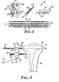
- FIG. 1 a tibial osteotomy guide assembly according to the present invention generally designated by the reference numeral 10.
- the guide assembly 10 comprises four generally cylindrical guide pins 12 of a suitable material, such as stainless steel, each having a cutting end surface 14 which may be of any suitable shape such as fluted or V-shaped as illustrated, and is adapted to cut bone tissue upon rotation of the guide pin about its axis with the cutting end surface 14 pressed against the bone tissue.
- a suitable material such as stainless steel
- all of the guide pins 12 have locating marks the same first predetermined distance from the tips of the cutting end surfaces 14, which marks are defined by shoulders 16 adjacent frusto-conical pin portions 18 which afford breaking the pins 12 at the shoulder 16 for reasons that will later be explained.
- the guide assembly 10 also includes a guide block 20 of a suitable material such as stainless steel or a ridged polymeric material.
- the guide block 20 has a first pair of spaced parallel guide bores 22 adapted to closely receive a first pair of the guide pins 12 and a plurality of second pairs of spaced parallel guide bores 24 adapted to receive the other or second pair of guide pins 12.
- Each of the second pairs of parallel guide bores 24 is oriented to direct the second pair of guide pins 12 so that a second plane tangent to and defined by the surfaces of the second pair of guide pins 12 adjacent the first pair of guide pins 12 will intersect a first plane tangent to and defined by the surfaces of the first pair of guide pins 12 adjacent the second pair of guide pins 12 at a different predetermined angle (e.g., angles of from 7-1/2 to 20 degrees in 2-1/2 degree increments) at a second predetermined distance from a side locating surface 26 of the guide block 20 through which the bores 22 and 24 open, and on the side of the block toward which the bores 22 and 24 converge.
- the first predetermined distance between the tips of the end surface 14 and the shoulders or marks 16 on the guide pins 12 and this second predetermined distance have a known relationship to each other to facilitate use of the assembly 10, which relationship in the illustrated assembly is that both distances are the same.
- An adjustment member 28 is adjustably mounted in the guide block 20 by being threadably engaged therewith for movement in a direction generally parallel to the first pair of guide bores 22.
- the adjustment member 28 has a conical end surface 30 adapted to engage the surface of a bone positioned on the side of the block 20 toward which the bores 22 and 24 converge, and has a knurled manually engageable knob 32 at its end opposite its end surface 30 by which the spacing between the end surface 30 and block locating surface 26 may be adjusted for reasons to be explained later.
- the guide assembly 10 includes a saw guide plate 34 having parallel through openings 36 spaced and shaped to slidably receive either the first or second pair of guide pins 12 located by the bores 22 and 24 of the guide block 20.
- the plate 34 has a planar guide surface 38 essentially tangent to both openings 36 through the guide plate which can be used to guide an oscillating saw during use of the guide assembly 10 as will later be explained.
- FIG. 2 the first pair of the guide pins 12 is inserted in a tibia 40 just below a knee joint 42 by rotating the pins 12 via a drill motor (not shown) through the first pair of bores 22 in the guide block 20 located so that the intersection of a plane through the axes of both pins 12 with a sagittal plane of the body is generally parallel to the plane of the knee joint 42, and the intersection of the plane through the axis of both pins 12 with a longitudinal plane of the body is generally parallel to or angled generally away from the plane of the knee joint 42 starting from the point 44 of insertion of the first pair of pins 12.
- the depth of insertion of the first pair of pins 12 is determined by feeling for the emergence of the tips of the pins 12 through the curved cortical shell of the tibia, such as at location 46.
- the guide block 20 is then located along the pins 12 with the locating surface 26 of the block 20 at a relationship with respect to the shoulder 16 or mark along at least one of the first pair of pins 12 that will, in the surgeon's judgment, leave an appropriate portion of the cortical shell of the tibia 40 adjacent the apex of the bone segment to be removed to act as a hinge about which the tibia 40 can be bent (the surgeon being mindful in such locating that the planes along which the cuts will be made will intersect at the tip of the guide pin 12 if the locating surface 26 is aligned with the mark 16 on the pin 12, or will intersect at the same distance and direction from the tip of the guide pins 12 that the locating surface 26 is positioned from the mark 16).
- the guide block 20 is then fixed in that position against movement toward the tibia 40 by manually rotating the adjustment member 28 via the knob 32 to place its end surface 30 against the side surface of the tibia 40.
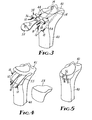
- the second pair of pins 12 is inserted into the tibia 40 disposed at a predetermined angle with respect to the first pair of pins 12 by inserting them through a preselected pair of the bores 24 so that the first and second planes defined by the adjacent surfaces of the two pairs of pins 12 will intersect within the tibia 40 adjacent its cortical shell on the side of the tibia 40 opposite the side from which the pins 12 are inserted with the line of intersection being generally parallel to a sagittal plane of the body.
- the location of the pins 12 and thus the planes can then be checked by an X-ray device, and .the guide pins 12 can be relocated if necessary.
- the guide block 20 is then removed by either breaking the block 20 at a thin section 50 between the pairs of guide bores 22 and 24 or breaking off the projecting parts of at least one pair of the pins 12 at the shoulder 16; and any remaining guide pins 12 that still have their original length are shortened to prevent their interference with the sawing operation by either breaking them at the shoulder 16, or severing them with a cutting tool (not shown).
- the saw guide plate 34 is then placed over one pair of pins 12 (Figure 3) with the pins 12 in its openings 36 and its guide surface 38 adjacent the other pair of pins 12; and a side surface 51 of an oscillating saw blade 52 driven by a suitable motor (not shown) is guided first along the guide surface 38 and then along the surfaces of both guide pins 12 to make a cut along the pins 12 from the outer surface of the tibia 40 to adjacent the intersection of the first and second planes defined by the pins 12.
- the pins 12 are then removed by either pulling them axially out of the tibia 40 or breaking them through the newly severed surface on the tibia 40, the cortical shell of the tibia 40 is bent ( Figure 5) adjacent the apex of the wedge-shaped groove to close the opening left by removing the segment 54 (which normally causes a "green twig” fracture in that portion of the cortical shell), the newly severed surfaces 55 are secured in face-to-face relationship as by staples 56, plates or other means, and the newly severed surfaces of the tibia 40 are allowed to heal together.
- the first predetermined distance between the tips of the locating pins 12 and the marks 16 on the locating pins 12 is the same as the second predetermined distance from the locating surface 26 to the intersection of the second plane defined by the second pair of locating pins 12 with the plane defined by the first pair of locating pins 12, these two predetermined distances need not be the same, but only need to have a known relationship.
- the second predetermined distance could, be shorter than the first predetermined distance by a known amount that would leave an appropriate amount of the cortical shell to act as a hinge for bending the tibia 40 when the tips of the first pair of pins 12 are aligned at the outer surface of that shell and the mark 16 is positioned at the locating surface.
- the guide assembly and method may be useful for removing wedge shaped segments from bones other than the tibia, such as from the femur, if desired to correct bone shapes.
Abstract
Description
- This invention relates to assemblies for use in removing wedge-shaped segments of bone, and particularly to such assemblies for removing such a segment from a tibia just below a knee joint.
- One known method for correcting varus (bowlegged) or valgus (knock-kneed) deformities in the tibia includes removing a wedge-shaped segment of the tibia extending generally transversely almost completely across the tibia just below the knee joint, bending the tibia to close the space left by removal of the segment, fastening the tibia in its bent position and allowing the bone to heal in that position. Such a method, if properly done, can relieve painful knee conditions caused by disproportionate loading of one side of the knee joint due to such deformities. Achieving the proper orientation of the tibia for such relief, however, requires thorough study of the leg structure to determine the shape and orientation of the segment to be removed, and removal of a segment of precisely the predetermined shape and orientation. Otherwise any relief obtained may be only temporary.
- One prior art osteotomy guide for use in removing such a segment guides the path of a saw that cuts the wedge-shaped segment from a guide structure attached to the side of the tibia. Such a guide is bulky and thus difficult to precisely locate, however, and affords no positive way of checking after it is attached to be sure that the wedge that will be removed by its use will be removed precisely from the desired location on the tibia.
- Another prior art osteotomy guide for use in removing such a segment comprises two guide pins, including a first pin adapted to be inserted into the tibia just below and generally parallel to the plane of the knee joint, and a second pin adapted to be inserted into the tibia at an angle with respect to the first pin corresponding to the dihedral angle of the wedge-like segment desired to be removed. The surgeon guides the flat surface of an oscillating saw along the adjacent surfaces of the pins to cut the wedge-shaped segment from the tibia. The location of such guide pins can be checked by X-ray devices to be sure that they are accurately placed. Each pin makes only line contact with a planar side surface of the saw that it guides, however, so that the saw can cut along a number of different planes tangent to the surface of each pin, each of which planes will result in a slightly different dihedral angle for the segment removed, and a different orientation of the line of intersection of the cutting planes that define the hinge line about which the tibia is bent after the segment is removed. Thus it is easily possible to cut out and remove a segment that affords more or less correction than is desired, and that results in the tibia being bent in a sagittal plane as well as a longitudinal plane of the body, which may not be a desired result.
- The present invention provides a tibial osteotomy guide assembly for use in correcting varus (bowlegged) or valgus (knock-kneed) deformities via removal of a wedge-shaped segment of the tibia, which guide assembly provides an accurate dihedral angle and
location for the segment of bone removed from the tibia that can be checked before the segment is actually removed so that the desired corrective result may be more accurately obtained. - The method for performing a tibial osteotomy using the assembly of the present invention comprises the steps of first inserting a first pair of parallel guide pins in the tibia just below the knee joint so that the intersection of a plane through the axes of both pins with a sagittal plane of the body is generally parallel to the plane of the knee joint, and the intersection of the plane through the axis of both pins with a longitudinal plane of the body is generally parallel to or angled generally away from the plane of the knee joint starting from the point of insertion of the pins. Next, a second pair of parallel guide pins is inserted in the tibia below the first pair, which second pair of guide pins is disposed at a predetermined angle with respect to the first pair of pins so that planes tangent to and defined by the surfaces of each pair of guide pins adjacent the other pair of guide pins will intersect within the tibia adjacent its cortical shell on the side of the tibia opposite the side from which the pins are inserted with the line of intersection between these intersecting planes being generally along a sagittal plane of the body. An oscillating saw blade is then guided along the surfaces of each pair of guide pins adjacent the other pair of guide pins to cut a wedge-shaped segment from the tibia along those intersecting planes. The segment and pairs of guide pins are removed from the tibia, the cortical shell of the tibia is bent generally about an axis defined by the line of intersection of those planes to close the space left by the removed segment and bring the newly severed surfaces into face-to-face engagement, the tibia is fastened in that bent condition and the newly severed surfaces are allowed to heal together.
- With two parallel guide pins serving as guides for each cut of the saw, it is relatively easy for the surgeon to accurately cut a wedge of a shape and location dictated by the position of the pins, and the location of the pins can be checked after they are inserted and before cutting begins through the use of an X-ray device.
- The pins each have a cutting end surface adapted to cut bone tissue upon rotation of the guide pin about its axis with the cutting end surface pressed against the bone tissue so that the pins can be inserted in the manner of a drill through the use of a drill motor; and the pins are accurately located through the use of a guide block having a first pair of spaced parallel guide bores adapted to closely receive and guide the first pair of guide pins as they are inserted into the tibia and a second pair of spaced parallel guide bores adapted to receive and guide the second pair of guide pins as they are inserted. The second pair of parallel guide bores is oriented to direct the second pair of guide pins as they are inserted so that a second plane tangent to and defined by the surfaces of the second pair of guide pins adjacent the first pair of pins will intersect a first plane tangent to and defined by the surfaces of the first pair of pins adjacent the second pair of pins at a predetermined angle and at a second predetermined distance from a locating surface of the guide block, and a first predetermined distance related to the second predetermined distance (such as by being the same distance) is marked along the length of at least the first pair of guide pins. Thus after the first pair of guide pins is inserted a desired depth into the tibia through the guide block (which depth can be determined by feeling the emergence of the tips of the pins through the curved cortical shell of the tibia), the guide block is located along the first pair of guide pins with the locating surface of the block at a relationship with respect to the locating mark along at least one of the first pair of pins that will, in the surgeon's judgment, leave an appropriate portion of the cortical shell adjacent the apex of the bone segment to be removed to act as a hinge about which the tibia can be bent. The guide block is then fixed in this position against movement toward the tibia by means on the locating block, which means may be in the form of an adjustment member adjustably mounted in the guide block for movement in a direction generally parallel to the first pair of guide bores that has an end surface adapted to engage the surface of the tibia positioned on the side of the block toward which the bores converge.
- The second pair of guide pins is then inserted into the tibia through the second pair of guide bores, the guide block is removed by either breaking the block at a thin section between the pairs of guide bores or breaking off the projecting parts of at least one pair of the pins, and the side surfaces of the pins remaining inthe tibia are used to guide the side surface of an oscillating saw cutting the segment from the tibia in the manner described above. Such guiding of the saw can be facilitated through the use of a guide plate having parallel through openings spaced and shaped to slidably engage either pair of guide pins located by the locating block, and having a planar surface essentially parallel to a plane tangent to its through openings (and thus the plane defining surfaces of the engaged pair of guide pins) along which the saw blade is guided as it enters the tibia.
- Preferably the guide block has a plurality of second pairs of guide bores, each second pair being adapted to receive the second pair of guide pins and being oriented to direct the second pair of guide pins so that the second plane defined by the second pair of guide pins will intersect the first plane defined by the first pair of guide pins at a different predetermined angle at the second predetermined distance from the surface on the block. Thus the same guide block will allow a surgeon a choice of dihedral angles for the segment of tibia to be removed.
- The invention will be further described with reference to the accompanying drawing wherein like numbers refer to like parts in the several views, and wherein:
- Figure 1 is a view, partially in perspective, of a tibial osteotomy guide assembly according to the present invention; and
- Figures 2 through 5 are perspective views sequentially illustrating a method according to the present invention which uses the guide assembly of Figure 1 to remove a wedge-shaped segment from a tibia.
- Referring now to the drawing there is shown in Figure 1 a tibial osteotomy guide assembly according to the present invention generally designated by the reference numeral 10.
- The guide assembly 10 comprises four generally
cylindrical guide pins 12 of a suitable material, such as stainless steel, each having acutting end surface 14 which may be of any suitable shape such as fluted or V-shaped as illustrated, and is adapted to cut bone tissue upon rotation of the guide pin about its axis with thecutting end surface 14 pressed against the bone tissue. At least two, and as illustrated, all of theguide pins 12 have locating marks the same first predetermined distance from the tips of thecutting end surfaces 14, which marks are defined byshoulders 16 adjacent frusto-conical pin portions 18 which afford breaking thepins 12 at theshoulder 16 for reasons that will later be explained. - The guide assembly 10 also includes a
guide block 20 of a suitable material such as stainless steel or a ridged polymeric material. Theguide block 20 has a first pair of spacedparallel guide bores 22 adapted to closely receive a first pair of theguide pins 12 and a plurality of second pairs of spacedparallel guide bores 24 adapted to receive the other or second pair ofguide pins 12. Each of the second pairs ofparallel guide bores 24 is oriented to direct the second pair ofguide pins 12 so that a second plane tangent to and defined by the surfaces of the second pair ofguide pins 12 adjacent the first pair ofguide pins 12 will intersect a first plane tangent to and defined by the surfaces of the first pair ofguide pins 12 adjacent the second pair ofguide pins 12 at a different predetermined angle (e.g., angles of from 7-1/2 to 20 degrees in 2-1/2 degree increments) at a second predetermined distance from aside locating surface 26 of theguide block 20 through which thebores bores end surface 14 and the shoulders ormarks 16 on theguide pins 12 and this second predetermined distance have a known relationship to each other to facilitate use of the assembly 10, which relationship in the illustrated assembly is that both distances are the same. - An
adjustment member 28 is adjustably mounted in theguide block 20 by being threadably engaged therewith for movement in a direction generally parallel to the first pair ofguide bores 22. Theadjustment member 28 has aconical end surface 30 adapted to engage the surface of a bone positioned on the side of theblock 20 toward which thebores engageable knob 32 at its end opposite itsend surface 30 by which the spacing between theend surface 30 andblock locating surface 26 may be adjusted for reasons to be explained later. - Also the guide assembly 10 includes a
saw guide plate 34 having parallel throughopenings 36 spaced and shaped to slidably receive either the first or second pair ofguide pins 12 located by thebores guide block 20. Theplate 34 has aplanar guide surface 38 essentially tangent to bothopenings 36 through the guide plate which can be used to guide an oscillating saw during use of the guide assembly 10 as will later be explained. - The method according to the present invention for performing a tibial osteotomy through the use of the guide assembly 10 will now be explained with reference to Figures 2 through 4. First, (Figure 2) the first pair of the
guide pins 12 is inserted in atibia 40 just below aknee joint 42 by rotating thepins 12 via a drill motor (not shown) through the first pair ofbores 22 in theguide block 20 located so that the intersection of a plane through the axes of bothpins 12 with a sagittal plane of the body is generally parallel to the plane of theknee joint 42, and the intersection of the plane through the axis of bothpins 12 with a longitudinal plane of the body is generally parallel to or angled generally away from the plane of theknee joint 42 starting from thepoint 44 of insertion of the first pair ofpins 12. The depth of insertion of the first pair ofpins 12 is determined by feeling for the emergence of the tips of thepins 12 through the curved cortical shell of the tibia, such as atlocation 46. Theguide block 20 is then located along thepins 12 with the locatingsurface 26 of theblock 20 at a relationship with respect to theshoulder 16 or mark along at least one of the first pair ofpins 12 that will, in the surgeon's judgment, leave an appropriate portion of the cortical shell of thetibia 40 adjacent the apex of the bone segment to be removed to act as a hinge about which thetibia 40 can be bent (the surgeon being mindful in such locating that the planes along which the cuts will be made will intersect at the tip of theguide pin 12 if the locatingsurface 26 is aligned with themark 16 on thepin 12, or will intersect at the same distance and direction from the tip of theguide pins 12 that the locatingsurface 26 is positioned from the mark 16). Theguide block 20 is then fixed in that position against movement toward thetibia 40 by manually rotating theadjustment member 28 via theknob 32 to place itsend surface 30 against the side surface of thetibia 40. Next, the second pair ofpins 12 is inserted into thetibia 40 disposed at a predetermined angle with respect to the first pair ofpins 12 by inserting them through a preselected pair of thebores 24 so that the first and second planes defined by the adjacent surfaces of the two pairs ofpins 12 will intersect within thetibia 40 adjacent its cortical shell on the side of thetibia 40 opposite the side from which thepins 12 are inserted with the line of intersection being generally parallel to a sagittal plane of the body. The location of thepins 12 and thus the planes can then be checked by an X-ray device, and .theguide pins 12 can be relocated if necessary. - The
guide block 20 is then removed by either breaking theblock 20 at athin section 50 between the pairs ofguide bores pins 12 at theshoulder 16; and anyremaining guide pins 12 that still have their original length are shortened to prevent their interference with the sawing operation by either breaking them at theshoulder 16, or severing them with a cutting tool (not shown). - The
saw guide plate 34 is then placed over one pair of pins 12 (Figure 3) with thepins 12 in itsopenings 36 and itsguide surface 38 adjacent the other pair ofpins 12; and aside surface 51 of anoscillating saw blade 52 driven by a suitable motor (not shown) is guided first along theguide surface 38 and then along the surfaces of bothguide pins 12 to make a cut along thepins 12 from the outer surface of thetibia 40 to adjacent the intersection of the first and second planes defined by thepins 12. After such a cut via the use of theguide plate 34 is made along the planes defined by the adjacent surfaces of both sets ofpins 12, a wedge-shaped segment 54 of thetibia 40 is removed (Figure 4) and any excess bone tissue at the apex of the wedge-shaped groove formed by thesaw blade 52 is removed through the use of an osteotome or chisel. Thepins 12 are then removed by either pulling them axially out of thetibia 40 or breaking them through the newly severed surface on thetibia 40, the cortical shell of thetibia 40 is bent (Figure 5) adjacent the apex of the wedge-shaped groove to close the opening left by removing the segment 54 (which normally causes a "green twig" fracture in that portion of the cortical shell), the newly severedsurfaces 55 are secured in face-to-face relationship as bystaples 56, plates or other means, and the newly severed surfaces of thetibia 40 are allowed to heal together. - As will be appreciated by those skilled in the art, many variations of the method and osteotomy guide assembly described above may be used without departing from the spirit of the present invention. For example, while as described and illustrated the first predetermined distance between the tips of the locating
pins 12 and themarks 16 on the locatingpins 12 is the same as the second predetermined distance from the locatingsurface 26 to the intersection of the second plane defined by the second pair of locatingpins 12 with the plane defined by the first pair of locatingpins 12, these two predetermined distances need not be the same, but only need to have a known relationship. The second predetermined distance could, be shorter than the first predetermined distance by a known amount that would leave an appropriate amount of the cortical shell to act as a hinge for bending thetibia 40 when the tips of the first pair ofpins 12 are aligned at the outer surface of that shell and themark 16 is positioned at the locating surface. Also, the guide assembly and method may be useful for removing wedge shaped segments from bones other than the tibia, such as from the femur, if desired to correct bone shapes. Thus the scope of the present invention should not be limited to the structures and steps described herein, but only by the structures and steps recited in the dependent claims and their equivalents.
Claims (8)
Applications Claiming Priority (2)
| Application Number | Priority Date | Filing Date | Title |
|---|---|---|---|
| US380412 | 1982-05-20 | ||
| US06/380,412 US4421112A (en) | 1982-05-20 | 1982-05-20 | Tibial osteotomy guide assembly and method |
Publications (3)
| Publication Number | Publication Date |
|---|---|
| EP0095296A2 true EP0095296A2 (en) | 1983-11-30 |
| EP0095296A3 EP0095296A3 (en) | 1984-07-25 |
| EP0095296B1 EP0095296B1 (en) | 1988-01-27 |
Family
ID=23501069
Family Applications (1)
| Application Number | Title | Priority Date | Filing Date |
|---|---|---|---|
| EP83302752A Expired EP0095296B1 (en) | 1982-05-20 | 1983-05-16 | Tibial osteotomy guide assembly and method |
Country Status (5)
| Country | Link |
|---|---|
| US (1) | US4421112A (en) |
| EP (1) | EP0095296B1 (en) |
| JP (1) | JPS58209343A (en) |
| CA (1) | CA1193509A (en) |
| DE (1) | DE3375451D1 (en) |
Cited By (14)
| Publication number | Priority date | Publication date | Assignee | Title |
|---|---|---|---|---|
| EP0121142A1 (en) * | 1983-03-09 | 1984-10-10 | Dow Corning Corporation | Apparatus for shaping a distal femoral surface |
| WO1985004092A1 (en) * | 1984-03-14 | 1985-09-26 | Magnus Odensten | A drill guiding and aligning device and a drill rod and a milling device to be used in connection therewith |
| FR2629339A1 (en) * | 1988-04-01 | 1989-10-06 | Broc Christian | LAYING MATERIAL FOR PARTICULARLY A TIBIAL AND / OR FEMORAL ELEMENT OF A BI-COMPARTMENTAL KNEE JOINT PROSTHESIS |
| WO1990001299A1 (en) * | 1988-07-29 | 1990-02-22 | Gregory James Roger | Further improved method and apparatus for removing prosthetic cement |
| AU603747B2 (en) * | 1986-12-24 | 1990-11-22 | Orthomet, Inc. | Bone cutting guide and methods for using same |
| FR2679126A1 (en) * | 1991-06-26 | 1993-01-22 | Chagneau Francis | Surgical device for performing an osteotomy |
| US5192321A (en) * | 1989-03-29 | 1993-03-09 | Andrew Strokon | Apparatus and method for knee surgery |
| WO1993011713A1 (en) * | 1991-12-13 | 1993-06-24 | Dietmar Pennig | Pilot device for inserting a screw into the neck of the femur |
| FR2721195A1 (en) * | 1994-06-21 | 1995-12-22 | Jacques Afriat | Guide for fitting osteotomy plate |
| US8728084B2 (en) | 2011-06-27 | 2014-05-20 | Biomet Sports Medicine, Llc | Apparatus for repairing bone defects |
| WO2014147604A2 (en) | 2013-03-19 | 2014-09-25 | Quadrante Do Futuro, Unipessoal Lda | Dynamic osteotomy plate including devices, apparatus and methods using such a plate |
| US8870884B2 (en) | 2011-06-27 | 2014-10-28 | Biomet Sports Medicine, Llc | Method for repairing bone defects |
| FR3018185A1 (en) * | 2014-03-07 | 2015-09-11 | Ostesys | POSITIONING INSTRUMENT OF OSTEOTOMY TOOL HOLDERS |
| US11266449B2 (en) | 2017-12-19 | 2022-03-08 | Orthopediatrics Corp | Osteotomy device and methods |
Families Citing this family (234)
| Publication number | Priority date | Publication date | Assignee | Title |
|---|---|---|---|---|
| US4467801A (en) * | 1983-03-09 | 1984-08-28 | Wright Manufacturing Company | Method and apparatus for shaping a proximal tibial surface |
| US4566448A (en) * | 1983-03-07 | 1986-01-28 | Rohr Jr William L | Ligament tensor and distal femoral resector guide |
| US4672957A (en) * | 1983-10-04 | 1987-06-16 | South African Inventions Development Corporation | Surgical device |
| US4677973A (en) * | 1985-05-28 | 1987-07-07 | Barclay Slocum | Proximal, tibial osteotomy for leveling a tibial plateau |
| US4744353A (en) * | 1986-04-18 | 1988-05-17 | Mcfarland Joseph R | Method for attaching soft tissue to bone tissue |
| US4759351A (en) * | 1986-12-29 | 1988-07-26 | Slocum D Barclay | Osteotomy method for biomechanical femoral neck lengthening and torsion |
| US4815467A (en) * | 1987-03-13 | 1989-03-28 | Chestnut William J | Acromioplasty guide pins |
| US5002546A (en) * | 1987-04-13 | 1991-03-26 | Romano Jack W | Curved bore drilling apparatus |
| US4941466A (en) * | 1987-04-13 | 1990-07-17 | Romano Jack W | Curved bore drilling method and apparatus |
| DE3878156T2 (en) * | 1987-10-21 | 1993-05-27 | Smith & Nephew Richards Inc | SURGICAL INSTRUMENT. |
| US4862881A (en) * | 1988-06-20 | 1989-09-05 | Shea Jr Cyril E | Orthopaedic appliance |
| US4892093A (en) * | 1988-10-28 | 1990-01-09 | Osteonics Corp. | Femoral cutting guide |
| US5002545A (en) * | 1989-01-30 | 1991-03-26 | Dow Corning Wright Corporation | Tibial surface shaping guide for knee implants |
| US4927422A (en) * | 1989-08-31 | 1990-05-22 | Boehringer Mannheim Corporation | Elbow arthroplasty instrumentation and surgical procedure |
| US5041117A (en) * | 1989-08-31 | 1991-08-20 | Boehringer Mannheim Corporation | Elbow arthroplasty instrumentation and surgical procedure |
| US5171244A (en) * | 1990-01-08 | 1992-12-15 | Caspari Richard B | Methods and apparatus for arthroscopic prosthetic knee replacement |
| US5078719A (en) * | 1990-01-08 | 1992-01-07 | Schreiber Saul N | Osteotomy device and method therefor |
| US5246444A (en) * | 1990-01-08 | 1993-09-21 | Schreiber Saul N | Osteotomy device and method |
| EP0513228B1 (en) * | 1990-02-09 | 1999-09-29 | Jack W. Romano | Curved bore drilling apparatus |
| US5129909A (en) * | 1991-03-13 | 1992-07-14 | Sutherland Charles J | Apparatus and method for making precise bone cuts in total knee replacement |
| US5254119A (en) * | 1991-08-23 | 1993-10-19 | Schreiber Saul N | Osteotomy device and method therefor |
| US5449360A (en) * | 1991-08-23 | 1995-09-12 | Schreiber; Saul N. | Osteotomy device and method |
| US5439467A (en) * | 1991-12-03 | 1995-08-08 | Vesica Medical, Inc. | Suture passer |
| US5766221A (en) * | 1991-12-03 | 1998-06-16 | Boston Scientific Technology, Inc. | Bone anchor implantation device |
| US6001104A (en) * | 1991-12-03 | 1999-12-14 | Boston Scientific Technology, Inc. | Bone anchor implantation device |
| ES2128811T3 (en) * | 1991-12-03 | 1999-05-16 | Boston Scient Ireland Ltd | SUTURE PIN. |
| WO1993010715A2 (en) * | 1991-12-03 | 1993-06-10 | Vesitec Medical, Inc. | Surgical treatment of stress urinary incontinence |
| US5683400A (en) * | 1991-12-13 | 1997-11-04 | Mcguire; David A. | Graft preparation table |
| US5366457A (en) * | 1991-12-13 | 1994-11-22 | David A. McGuire | Method and apparatus for preparing a bone and tendon graft |
| US5324295A (en) * | 1992-04-24 | 1994-06-28 | Shapiro Michael R | Drill guide for surgical pins |
| US5306278A (en) * | 1992-09-11 | 1994-04-26 | Ace Medical Company | Corticotomy drill guide |
| GB9221257D0 (en) * | 1992-10-09 | 1992-11-25 | Minnesota Mining & Mfg | Glenoid alignment guide |
| US5702485A (en) * | 1992-11-20 | 1997-12-30 | Burke; Dennis W. | Collared prosthetic device with centering fins |
| WO1994012123A1 (en) * | 1992-11-20 | 1994-06-09 | Burke Dennis W | Improved femoral implant collar and installation apparatus |
| US5951606A (en) | 1992-11-20 | 1999-09-14 | Burke; Dennis W. | Centering device for femoral implant and method and apparatus for implementation thereof |
| US5423822A (en) * | 1993-01-27 | 1995-06-13 | Biomet, Inc. | Method and apparatus for preparing a bone for receiving a prosthetic device |
| US5509918A (en) * | 1993-05-11 | 1996-04-23 | David Romano | Method and apparatus for drilling a curved bore in an object |
| US5431660A (en) * | 1993-11-30 | 1995-07-11 | Burke; Dennis W. | Spring loaded screw and driver/extractor therefor |
| US5540695A (en) * | 1994-02-18 | 1996-07-30 | Howmedica Inc. | Osteotomy cutting guide |
| US5484446A (en) * | 1994-06-27 | 1996-01-16 | Zimmer, Inc. | Alignment guide for use in orthopaedic surgery |
| US8603095B2 (en) | 1994-09-02 | 2013-12-10 | Puget Bio Ventures LLC | Apparatuses for femoral and tibial resection |
| US6695848B2 (en) | 1994-09-02 | 2004-02-24 | Hudson Surgical Design, Inc. | Methods for femoral and tibial resection |
| US5613969A (en) * | 1995-02-07 | 1997-03-25 | Jenkins, Jr.; Joseph R. | Tibial osteotomy system |
| US5693048A (en) * | 1995-03-13 | 1997-12-02 | Zimmer, Inc. | Intramedullary rod guide member lock |
| US5601565A (en) * | 1995-06-02 | 1997-02-11 | Huebner; Randall J. | Osteotomy method and apparatus |
| US5722978A (en) * | 1996-03-13 | 1998-03-03 | Jenkins, Jr.; Joseph Robert | Osteotomy system |
| US5667512A (en) * | 1996-05-03 | 1997-09-16 | Metagen, Llc | Patellar resection guide |
| US5718717A (en) | 1996-08-19 | 1998-02-17 | Bonutti; Peter M. | Suture anchor |
| US6053935A (en) * | 1996-11-08 | 2000-04-25 | Boston Scientific Corporation | Transvaginal anchor implantation device |
| US5980526A (en) * | 1997-02-12 | 1999-11-09 | Orthopaedic Innovations, Inc. | Wedge osteotomy device including a guide for controlling osteotomy depth |
| US6096041A (en) * | 1998-01-27 | 2000-08-01 | Scimed Life Systems, Inc. | Bone anchors for bone anchor implantation device |
| US6045551A (en) | 1998-02-06 | 2000-04-04 | Bonutti; Peter M. | Bone suture |
| GR1003028B (en) * | 1998-02-25 | 1998-12-10 | �. ���/��� | Aiming device for introducing guide wires into bone |
| US6059789A (en) * | 1998-06-22 | 2000-05-09 | Xomed Surgical Products, Inc. | Drill guide for creating a tunnel in bone for fixating soft tissue to the bone and kit and method for fixating soft tissue to bone |
| US6086593A (en) | 1998-06-30 | 2000-07-11 | Bonutti; Peter M. | Method and apparatus for use in operating on a bone |
| US6099531A (en) * | 1998-08-20 | 2000-08-08 | Bonutti; Peter M. | Changing relationship between bones |
| US6200323B1 (en) * | 1998-12-04 | 2001-03-13 | Pierson, Iii Raymond H. | Bone depth resection guide and method |
| US6042584A (en) * | 1998-12-04 | 2000-03-28 | Pierson, Iii; Raymond H. | Bone depth resection guide and method |
| US6203546B1 (en) * | 1999-07-27 | 2001-03-20 | Macmahon Edward B | Method and apparatus for medial tibial osteotomy |
| US6447516B1 (en) | 1999-08-09 | 2002-09-10 | Peter M. Bonutti | Method of securing tissue |
| US6368343B1 (en) | 2000-03-13 | 2002-04-09 | Peter M. Bonutti | Method of using ultrasonic vibration to secure body tissue |
| DE29913994U1 (en) * | 1999-08-11 | 2000-12-21 | Synthes Ag | Surgical guide plate |
| US7635390B1 (en) | 2000-01-14 | 2009-12-22 | Marctec, Llc | Joint replacement component having a modular articulating surface |
| US6702821B2 (en) | 2000-01-14 | 2004-03-09 | The Bonutti 2003 Trust A | Instrumentation for minimally invasive joint replacement and methods for using same |
| US6635073B2 (en) | 2000-05-03 | 2003-10-21 | Peter M. Bonutti | Method of securing body tissue |
| US7547307B2 (en) | 2001-02-27 | 2009-06-16 | Smith & Nephew, Inc. | Computer assisted knee arthroplasty instrumentation, systems, and processes |
| US8062377B2 (en) | 2001-03-05 | 2011-11-22 | Hudson Surgical Design, Inc. | Methods and apparatus for knee arthroplasty |
| US8033983B2 (en) | 2001-03-09 | 2011-10-11 | Boston Scientific Scimed, Inc. | Medical implant |
| US8162816B2 (en) | 2001-03-09 | 2012-04-24 | Boston Scientific Scimed, Inc. | System for implanting an implant and method thereof |
| JP4181410B2 (en) | 2001-03-09 | 2008-11-12 | ボストン サイエンティフィック リミテッド | System and method for implanting an implant |
| US6796986B2 (en) | 2001-03-29 | 2004-09-28 | David W. Duffner | Adjustable tibial osteotomy jig and method |
| US9463058B2 (en) | 2013-12-05 | 2016-10-11 | Acumed Llc | Guide for surgical wires, method, system, and device |
| US7708741B1 (en) | 2001-08-28 | 2010-05-04 | Marctec, Llc | Method of preparing bones for knee replacement surgery |
| US7060074B2 (en) * | 2001-11-28 | 2006-06-13 | Wright Medical Technology, Inc. | Instrumentation for minimally invasive unicompartmental knee replacement |
| US7141053B2 (en) * | 2001-11-28 | 2006-11-28 | Wright Medical Technology, Inc. | Methods of minimally invasive unicompartmental knee replacement |
| US6719765B2 (en) | 2001-12-03 | 2004-04-13 | Bonutti 2003 Trust-A | Magnetic suturing system and method |
| CA2475979A1 (en) | 2002-02-11 | 2003-08-21 | Smith & Nephew, Inc. | Image-guided fracture reduction |
| US7131973B2 (en) | 2002-05-16 | 2006-11-07 | Boston Scientific Scimed, Inc. | Bone anchor implantation device |
| SE524413C2 (en) * | 2002-05-23 | 2004-08-03 | Claes-Olof Stiernborg | Meringue instruments, for example for hallux surgery |
| US7935118B2 (en) | 2002-06-21 | 2011-05-03 | Depuy Products, Inc. | Prosthesis removal cutting guide, cutting tool and method |
| US20030236522A1 (en) | 2002-06-21 | 2003-12-25 | Jack Long | Prosthesis cavity cutting guide, cutting tool and method |
| EP1581148B1 (en) | 2002-12-17 | 2010-02-17 | Boston Scientific Limited | Spacer for sling delivery system |
| US7905883B2 (en) * | 2003-03-26 | 2011-03-15 | Greatbatch Medical S.A. | Locking triple pelvic osteotomy plate and method of use |
| DE602004028451D1 (en) * | 2003-03-26 | 2010-09-16 | Swiss Orthopedic Solutions Sa | FIXING BONE PLATE |
| US7722653B2 (en) | 2003-03-26 | 2010-05-25 | Greatbatch Medical S.A. | Locking bone plate |
| JP2004298259A (en) * | 2003-03-28 | 2004-10-28 | Zimmer Kk | Tool for upper tibia osteotomy |
| US7559931B2 (en) | 2003-06-09 | 2009-07-14 | OrthAlign, Inc. | Surgical orientation system and method |
| US7361138B2 (en) | 2003-07-31 | 2008-04-22 | Scimed Life Systems, Inc. | Bioabsorbable casing for surgical sling assembly |
| US7862570B2 (en) | 2003-10-03 | 2011-01-04 | Smith & Nephew, Inc. | Surgical positioners |
| US7764985B2 (en) | 2003-10-20 | 2010-07-27 | Smith & Nephew, Inc. | Surgical navigation system component fault interfaces and related processes |
| DE602004031147D1 (en) | 2003-11-14 | 2011-03-03 | Smith & Nephew Inc | |
| US7815645B2 (en) * | 2004-01-14 | 2010-10-19 | Hudson Surgical Design, Inc. | Methods and apparatus for pinplasty bone resection |
| US20060030854A1 (en) | 2004-02-02 | 2006-02-09 | Haines Timothy G | Methods and apparatus for wireplasty bone resection |
| US7857814B2 (en) | 2004-01-14 | 2010-12-28 | Hudson Surgical Design, Inc. | Methods and apparatus for minimally invasive arthroplasty |
| US8021368B2 (en) | 2004-01-14 | 2011-09-20 | Hudson Surgical Design, Inc. | Methods and apparatus for improved cutting tools for resection |
| US8114083B2 (en) | 2004-01-14 | 2012-02-14 | Hudson Surgical Design, Inc. | Methods and apparatus for improved drilling and milling tools for resection |
| US20060030855A1 (en) | 2004-03-08 | 2006-02-09 | Haines Timothy G | Methods and apparatus for improved profile based resection |
| US20050192588A1 (en) * | 2004-02-27 | 2005-09-01 | Garcia Daniel X. | Instrumentation and method for prosthetic knee |
| US7641660B2 (en) | 2004-03-08 | 2010-01-05 | Biomet Manufacturing Corporation | Method, apparatus, and system for image guided bone cutting |
| US8114086B2 (en) | 2004-03-08 | 2012-02-14 | Zimmer Technology, Inc. | Navigated cut guide locator |
| US7993341B2 (en) | 2004-03-08 | 2011-08-09 | Zimmer Technology, Inc. | Navigated orthopaedic guide and method |
| WO2006091827A2 (en) | 2005-02-25 | 2006-08-31 | Regents Of The University Of California | Device and template for canine humeral slide osteotomy |
| US20080045960A1 (en) * | 2004-03-25 | 2008-02-21 | Bruecker Kenneth | Locking tpo plate and method of use |
| US7846165B2 (en) * | 2004-03-29 | 2010-12-07 | Depuy Products, Inc. | Method and apparatus for arthroscopic bone preparation |
| WO2005096982A1 (en) | 2004-03-31 | 2005-10-20 | Smith & Nephew, Inc. | Methods and apparatuses for providing a reference array input device |
| EP1737375B1 (en) | 2004-04-21 | 2021-08-11 | Smith & Nephew, Inc | Computer-aided navigation systems for shoulder arthroplasty |
| US20050251147A1 (en) * | 2004-05-07 | 2005-11-10 | Novak Vincent P | Open wedge osteotomy system and surgical method |
| US20050273112A1 (en) * | 2004-05-26 | 2005-12-08 | Mcnamara Michael G | Three-dimensional osteotomy device and method for treating bone deformities |
| US20060025775A1 (en) * | 2004-07-28 | 2006-02-02 | Howmedica Osteonics Corp. | Femoral neck resection guide and method |
| US7819873B1 (en) * | 2004-09-21 | 2010-10-26 | Biomet Manufacturing Corp. | Method and apparatus for fixation of surgical instruments |
| WO2006062518A2 (en) | 2004-12-08 | 2006-06-15 | Interpore Spine Ltd. | Continuous phase composite for musculoskeletal repair |
| US20070038303A1 (en) * | 2006-08-15 | 2007-02-15 | Ebi, L.P. | Foot/ankle implant and associated method |
| US8535357B2 (en) | 2004-12-09 | 2013-09-17 | Biomet Sports Medicine, Llc | Continuous phase compositions for ACL repair |
| US20060155293A1 (en) * | 2005-01-07 | 2006-07-13 | Zimmer Technology | External rotation cut guide |
| US20080147073A1 (en) * | 2005-01-31 | 2008-06-19 | Ammann Kelly G | Method and apparatus for performing an open wedge, high tibial osteotomy |
| US8906026B2 (en) | 2005-01-31 | 2014-12-09 | Arthrex, Inc. | Method and apparatus for performing an open wedge, high tibial osteotomy |
| US7935119B2 (en) * | 2005-01-31 | 2011-05-03 | Ibalance Medical, Inc. | Method for performing an open wedge, high tibial osteotomy |
| US20090054899A1 (en) * | 2005-01-31 | 2009-02-26 | Ammann Kelly G | Method and apparatus for performing an open wedge, high tibial osteotomy |
| US7967823B2 (en) * | 2005-01-31 | 2011-06-28 | Arthrex, Inc. | Method and apparatus for performing an open wedge, high tibial osteotomy |
| US8771279B2 (en) | 2005-01-31 | 2014-07-08 | Arthrex, Inc. | Method and apparatus for performing an osteotomy in bone |
| US8062301B2 (en) * | 2005-01-31 | 2011-11-22 | Arthrex, Inc. | Method and apparatus for performing a high tibial, dome osteotomy |
| US8540777B2 (en) * | 2005-01-31 | 2013-09-24 | Arthrex, Inc. | Method and apparatus for performing an open wedge, high tibial osteotomy |
| US8496662B2 (en) * | 2005-01-31 | 2013-07-30 | Arthrex, Inc. | Method and apparatus for forming a wedge-like opening in a bone for an open wedge osteotomy |
| JP2008529609A (en) * | 2005-02-09 | 2008-08-07 | アイバランス・メディカル・インコーポレーテッド | Multi-component implant for open knee osteotomy |
| AU2006216653B2 (en) | 2005-02-22 | 2012-03-15 | Smith & Nephew, Inc. | In-line milling system |
| AU2006232324A1 (en) * | 2005-04-01 | 2006-10-12 | Ibalance Medical, Inc. | Method and apparatus for performing an open wedge, high tibial osteotomy |
| US20070118140A1 (en) * | 2005-10-18 | 2007-05-24 | Aesculap Ag & Co. Kg | Method and apparatus for navigating a cutting tool during orthopedic surgery using a localization system |
| US7520880B2 (en) | 2006-01-09 | 2009-04-21 | Zimmer Technology, Inc. | Adjustable surgical support base with integral hinge |
| US7744600B2 (en) | 2006-01-10 | 2010-06-29 | Zimmer Technology, Inc. | Bone resection guide and method |
| US8506597B2 (en) * | 2011-10-25 | 2013-08-13 | Biomet Sports Medicine, Llc | Method and apparatus for interosseous membrane reconstruction |
| US9918740B2 (en) | 2006-02-27 | 2018-03-20 | Biomet Manufacturing, Llc | Backup surgical instrument system and method |
| US9289253B2 (en) | 2006-02-27 | 2016-03-22 | Biomet Manufacturing, Llc | Patient-specific shoulder guide |
| US8864769B2 (en) | 2006-02-27 | 2014-10-21 | Biomet Manufacturing, Llc | Alignment guides with patient-specific anchoring elements |
| US8407067B2 (en) | 2007-04-17 | 2013-03-26 | Biomet Manufacturing Corp. | Method and apparatus for manufacturing an implant |
| US9339278B2 (en) | 2006-02-27 | 2016-05-17 | Biomet Manufacturing, Llc | Patient-specific acetabular guides and associated instruments |
| US20150335438A1 (en) | 2006-02-27 | 2015-11-26 | Biomet Manufacturing, Llc. | Patient-specific augments |
| US8568487B2 (en) | 2006-02-27 | 2013-10-29 | Biomet Manufacturing, Llc | Patient-specific hip joint devices |
| US8608748B2 (en) | 2006-02-27 | 2013-12-17 | Biomet Manufacturing, Llc | Patient specific guides |
| US8535387B2 (en) | 2006-02-27 | 2013-09-17 | Biomet Manufacturing, Llc | Patient-specific tools and implants |
| US9345548B2 (en) | 2006-02-27 | 2016-05-24 | Biomet Manufacturing, Llc | Patient-specific pre-operative planning |
| US7967868B2 (en) | 2007-04-17 | 2011-06-28 | Biomet Manufacturing Corp. | Patient-modified implant and associated method |
| US9173661B2 (en) | 2006-02-27 | 2015-11-03 | Biomet Manufacturing, Llc | Patient specific alignment guide with cutting surface and laser indicator |
| US8133234B2 (en) | 2006-02-27 | 2012-03-13 | Biomet Manufacturing Corp. | Patient specific acetabular guide and method |
| US8473305B2 (en) | 2007-04-17 | 2013-06-25 | Biomet Manufacturing Corp. | Method and apparatus for manufacturing an implant |
| US8241293B2 (en) | 2006-02-27 | 2012-08-14 | Biomet Manufacturing Corp. | Patient specific high tibia osteotomy |
| US8603180B2 (en) | 2006-02-27 | 2013-12-10 | Biomet Manufacturing, Llc | Patient-specific acetabular alignment guides |
| US8092465B2 (en) | 2006-06-09 | 2012-01-10 | Biomet Manufacturing Corp. | Patient specific knee alignment guide and associated method |
| US9113971B2 (en) | 2006-02-27 | 2015-08-25 | Biomet Manufacturing, Llc | Femoral acetabular impingement guide |
| US8377066B2 (en) * | 2006-02-27 | 2013-02-19 | Biomet Manufacturing Corp. | Patient-specific elbow guides and associated methods |
| US10278711B2 (en) | 2006-02-27 | 2019-05-07 | Biomet Manufacturing, Llc | Patient-specific femoral guide |
| US8591516B2 (en) | 2006-02-27 | 2013-11-26 | Biomet Manufacturing, Llc | Patient-specific orthopedic instruments |
| US9907659B2 (en) | 2007-04-17 | 2018-03-06 | Biomet Manufacturing, Llc | Method and apparatus for manufacturing an implant |
| US8608749B2 (en) | 2006-02-27 | 2013-12-17 | Biomet Manufacturing, Llc | Patient-specific acetabular guides and associated instruments |
| US8858561B2 (en) | 2006-06-09 | 2014-10-14 | Blomet Manufacturing, LLC | Patient-specific alignment guide |
| US7704253B2 (en) * | 2006-03-06 | 2010-04-27 | Howmedica Osteonics Corp. | Single use resection guide |
| US9795399B2 (en) | 2006-06-09 | 2017-10-24 | Biomet Manufacturing, Llc | Patient-specific knee alignment guide and associated method |
| US8021369B2 (en) * | 2006-06-12 | 2011-09-20 | Howmedica Osteonics Corp. | Navigated femoral neck resection guide and method |
| US7678115B2 (en) * | 2006-06-21 | 2010-03-16 | Howmedia Osteonics Corp. | Unicondylar knee implants and insertion methods therefor |
| US8241292B2 (en) | 2006-06-30 | 2012-08-14 | Howmedica Osteonics Corp. | High tibial osteotomy system |
| US20110208200A1 (en) * | 2006-08-15 | 2011-08-25 | Gary Keffer | Veterinary precision fixation device and method of using the same |
| US20080044244A1 (en) * | 2006-08-15 | 2008-02-21 | Keffer Gary L | Veterinary precision fixation device and method of using the same |
| EP2086434B1 (en) | 2006-09-27 | 2016-03-23 | Arthrex, Inc. | Apparatus for performing an open wedge, high tibial osteotomy |
| US20080119860A1 (en) * | 2006-11-21 | 2008-05-22 | Howmedica Osteonics Corp. | System for preparing bone for receiving an implant |
| WO2008066756A2 (en) * | 2006-11-22 | 2008-06-05 | Ibalance Medical, Inc. | Method and apparatus for performing an open wedge, high tibial osteotomy |
| US20080208197A1 (en) * | 2006-11-30 | 2008-08-28 | Kelly Ammann | Method and apparatus for performing an open wedge, high tibial osteotomy |
| WO2008070027A2 (en) * | 2006-12-01 | 2008-06-12 | Ibalance Medical, Inc. | Method and apparatus for performing an open wedge, low femoral osteotomy |
| US8821500B2 (en) * | 2006-12-20 | 2014-09-02 | Howmedica Osteonics Corp. | Femoral cutting block |
| US8926618B2 (en) | 2007-04-19 | 2015-01-06 | Howmedica Osteonics Corp. | Cutting guide with internal distraction |
| US20090088804A1 (en) * | 2007-09-27 | 2009-04-02 | Depuy Products, Inc. | Plate holder assembly having movable guide component |
| US20090177203A1 (en) | 2008-01-04 | 2009-07-09 | Inbone Technologies, Inc. | Devices, systems and methods for re-alignment of bone |
| US8152846B2 (en) * | 2008-03-06 | 2012-04-10 | Musculoskeletal Transplant Foundation | Instrumentation and method for repair of meniscus tissue |
| ES2683029T3 (en) | 2008-07-24 | 2018-09-24 | OrthAlign, Inc. | Joint replacement systems |
| AU2009291743B2 (en) | 2008-09-10 | 2015-02-05 | Orthalign, Inc | Hip surgery systems and methods |
| US8192441B2 (en) * | 2008-10-03 | 2012-06-05 | Howmedica Osteonics Corp. | High tibial osteotomy instrumentation |
| US10869771B2 (en) * | 2009-07-24 | 2020-12-22 | OrthAlign, Inc. | Systems and methods for joint replacement |
| US8118815B2 (en) * | 2009-07-24 | 2012-02-21 | OrthAlign, Inc. | Systems and methods for joint replacement |
| DE102009028503B4 (en) | 2009-08-13 | 2013-11-14 | Biomet Manufacturing Corp. | Resection template for the resection of bones, method for producing such a resection template and operation set for performing knee joint surgery |
| US8632547B2 (en) * | 2010-02-26 | 2014-01-21 | Biomet Sports Medicine, Llc | Patient-specific osteotomy devices and methods |
| US9271744B2 (en) | 2010-09-29 | 2016-03-01 | Biomet Manufacturing, Llc | Patient-specific guide for partial acetabular socket replacement |
| US9968376B2 (en) | 2010-11-29 | 2018-05-15 | Biomet Manufacturing, Llc | Patient-specific orthopedic instruments |
| US9241745B2 (en) | 2011-03-07 | 2016-01-26 | Biomet Manufacturing, Llc | Patient-specific femoral version guide |
| US8715289B2 (en) | 2011-04-15 | 2014-05-06 | Biomet Manufacturing, Llc | Patient-specific numerically controlled instrument |
| US9675400B2 (en) | 2011-04-19 | 2017-06-13 | Biomet Manufacturing, Llc | Patient-specific fracture fixation instrumentation and method |
| US8956364B2 (en) | 2011-04-29 | 2015-02-17 | Biomet Manufacturing, Llc | Patient-specific partial knee guides and other instruments |
| US8668700B2 (en) | 2011-04-29 | 2014-03-11 | Biomet Manufacturing, Llc | Patient-specific convertible guides |
| US8532807B2 (en) | 2011-06-06 | 2013-09-10 | Biomet Manufacturing, Llc | Pre-operative planning and manufacturing method for orthopedic procedure |
| US9084618B2 (en) | 2011-06-13 | 2015-07-21 | Biomet Manufacturing, Llc | Drill guides for confirming alignment of patient-specific alignment guides |
| US8764760B2 (en) | 2011-07-01 | 2014-07-01 | Biomet Manufacturing, Llc | Patient-specific bone-cutting guidance instruments and methods |
| US20130001121A1 (en) | 2011-07-01 | 2013-01-03 | Biomet Manufacturing Corp. | Backup kit for a patient-specific arthroplasty kit assembly |
| US8597365B2 (en) | 2011-08-04 | 2013-12-03 | Biomet Manufacturing, Llc | Patient-specific pelvic implants for acetabular reconstruction |
| US9066734B2 (en) | 2011-08-31 | 2015-06-30 | Biomet Manufacturing, Llc | Patient-specific sacroiliac guides and associated methods |
| US9295497B2 (en) | 2011-08-31 | 2016-03-29 | Biomet Manufacturing, Llc | Patient-specific sacroiliac and pedicle guides |
| US9386993B2 (en) | 2011-09-29 | 2016-07-12 | Biomet Manufacturing, Llc | Patient-specific femoroacetabular impingement instruments and methods |
| US9301812B2 (en) | 2011-10-27 | 2016-04-05 | Biomet Manufacturing, Llc | Methods for patient-specific shoulder arthroplasty |
| KR20130046337A (en) | 2011-10-27 | 2013-05-07 | 삼성전자주식회사 | Multi-view device and contol method thereof, display apparatus and contol method thereof, and display system |
| US9554910B2 (en) | 2011-10-27 | 2017-01-31 | Biomet Manufacturing, Llc | Patient-specific glenoid guide and implants |
| EP3384858A1 (en) | 2011-10-27 | 2018-10-10 | Biomet Manufacturing, LLC | Patient-specific glenoid guides |
| US9451973B2 (en) | 2011-10-27 | 2016-09-27 | Biomet Manufacturing, Llc | Patient specific glenoid guide |
| US9237950B2 (en) | 2012-02-02 | 2016-01-19 | Biomet Manufacturing, Llc | Implant with patient-specific porous structure |
| JP2015517361A (en) | 2012-05-18 | 2015-06-22 | オースアライン・インコーポレイテッド | Apparatus and method for knee arthroplasty |
| US11857266B2 (en) | 2012-06-21 | 2024-01-02 | Globus Medical, Inc. | System for a surveillance marker in robotic-assisted surgery |
| US9649160B2 (en) | 2012-08-14 | 2017-05-16 | OrthAlign, Inc. | Hip replacement navigation system and method |
| JP5204921B1 (en) * | 2012-12-06 | 2013-06-05 | 多摩メディカル有限会社 | Medical guide pin with scale |
| US9204977B2 (en) | 2012-12-11 | 2015-12-08 | Biomet Manufacturing, Llc | Patient-specific acetabular guide for anterior approach |
| US9060788B2 (en) | 2012-12-11 | 2015-06-23 | Biomet Manufacturing, Llc | Patient-specific acetabular guide for anterior approach |
| US8920512B2 (en) | 2012-12-19 | 2014-12-30 | Biomet Sports Medicine, Llc | Method and apparatus for pre-forming a high tibial osteotomy |
| US9839438B2 (en) | 2013-03-11 | 2017-12-12 | Biomet Manufacturing, Llc | Patient-specific glenoid guide with a reusable guide holder |
| US9579107B2 (en) | 2013-03-12 | 2017-02-28 | Biomet Manufacturing, Llc | Multi-point fit for patient specific guide |
| US9826981B2 (en) | 2013-03-13 | 2017-11-28 | Biomet Manufacturing, Llc | Tangential fit of patient-specific guides |
| US9498233B2 (en) | 2013-03-13 | 2016-11-22 | Biomet Manufacturing, Llc. | Universal acetabular guide and associated hardware |
| US9517145B2 (en) | 2013-03-15 | 2016-12-13 | Biomet Manufacturing, Llc | Guide alignment system and method |
| US9848929B2 (en) * | 2013-08-12 | 2017-12-26 | Paragon 28, Inc. | Devices and method of achieving bone fusion |
| US20150112349A1 (en) | 2013-10-21 | 2015-04-23 | Biomet Manufacturing, Llc | Ligament Guide Registration |
| US10282488B2 (en) | 2014-04-25 | 2019-05-07 | Biomet Manufacturing, Llc | HTO guide with optional guided ACL/PCL tunnels |
| US9408616B2 (en) | 2014-05-12 | 2016-08-09 | Biomet Manufacturing, Llc | Humeral cut guide |
| US9839436B2 (en) | 2014-06-03 | 2017-12-12 | Biomet Manufacturing, Llc | Patient-specific glenoid depth control |
| US9561040B2 (en) | 2014-06-03 | 2017-02-07 | Biomet Manufacturing, Llc | Patient-specific glenoid depth control |
| US9826994B2 (en) | 2014-09-29 | 2017-11-28 | Biomet Manufacturing, Llc | Adjustable glenoid pin insertion guide |
| US9833245B2 (en) | 2014-09-29 | 2017-12-05 | Biomet Sports Medicine, Llc | Tibial tubercule osteotomy |
| WO2016126948A1 (en) * | 2015-02-04 | 2016-08-11 | Mark Sanders | Osteotomy guide and method of using the same |
| US10363149B2 (en) | 2015-02-20 | 2019-07-30 | OrthAlign, Inc. | Hip replacement navigation system and method |
| US9820868B2 (en) | 2015-03-30 | 2017-11-21 | Biomet Manufacturing, Llc | Method and apparatus for a pin apparatus |
| US10226262B2 (en) | 2015-06-25 | 2019-03-12 | Biomet Manufacturing, Llc | Patient-specific humeral guide designs |
| US10568647B2 (en) | 2015-06-25 | 2020-02-25 | Biomet Manufacturing, Llc | Patient-specific humeral guide designs |
| CA3100061A1 (en) | 2015-09-02 | 2017-03-09 | Wright Medical Technology, Inc. | Chevron osteotomy tools and methods |
| EP3364887A1 (en) * | 2015-10-22 | 2018-08-29 | Materialise N.V. | Two-part surgical guide |
| US10722310B2 (en) | 2017-03-13 | 2020-07-28 | Zimmer Biomet CMF and Thoracic, LLC | Virtual surgery planning system and method |
| AU2018236220A1 (en) | 2017-03-14 | 2019-09-26 | OrthAlign, Inc. | Hip replacement navigation systems and methods |
| JP7344122B2 (en) | 2017-03-14 | 2023-09-13 | オースアライン・インコーポレイテッド | Systems and methods for measuring and balancing soft tissue |
| US10966773B2 (en) * | 2017-07-31 | 2021-04-06 | DePuy Synthes Products, Inc. | Correction guide for femoral neck |
| EP3466350B1 (en) * | 2017-10-06 | 2020-07-22 | Stryker European Holdings I, LLC | Pedicle subtraction osteotomy guide |
| US10820915B2 (en) * | 2018-03-06 | 2020-11-03 | Medos International Sarl | Methods, systems, and devices for instability repair |
| DE102019104965A1 (en) * | 2019-02-27 | 2020-08-27 | Aesculap Ag | Fixation device for a tibia alignment system |
| CN112842454B (en) * | 2020-12-31 | 2022-05-10 | 福州市第二医院(福建省福州中西医结合医院、福州市职业病医院) | Guider for osteotomy around knee joint and application of guider |
Citations (3)
| Publication number | Priority date | Publication date | Assignee | Title |
|---|---|---|---|---|
| CH511016A (en) * | 1969-04-24 | 1971-08-15 | Osteo Ag | Osteotomy saw device |
| US4325373A (en) * | 1978-08-01 | 1982-04-20 | Carbo Mediec Inc. | Apparatus for forming an osteotomy for a dental implant |
| US4335715A (en) * | 1980-06-20 | 1982-06-22 | Kirkley William H | Osteotomy guide |
Family Cites Families (11)
| Publication number | Priority date | Publication date | Assignee | Title |
|---|---|---|---|---|
| US1201467A (en) * | 1915-04-26 | 1916-10-17 | Emil J Hoglund | Bone-cutting instrument. |
| US2200120A (en) * | 1938-04-30 | 1940-05-07 | Walter W Nauth | Fracture nail guide |
| US2500370A (en) * | 1947-06-30 | 1950-03-14 | Mckibbin Genevieve | Repair of femur fracture |
| US2737724A (en) * | 1950-10-11 | 1956-03-13 | James R Herz | Gauge for femoral trochanteric osteotomy |
| US2697433A (en) * | 1951-12-04 | 1954-12-21 | Max A Zehnder | Device for accurately positioning and guiding guide wires used in the nailing of thefemoral neck |
| US3073310A (en) * | 1957-08-05 | 1963-01-15 | Zenon R Mocarski | Surgical instrument positioning device |
| US3135263A (en) * | 1960-10-05 | 1964-06-02 | Smiths America Corp | Surgical instrument positioning device |
| GB1161312A (en) * | 1965-09-17 | 1969-08-13 | Nat Res Dev | Fixation Implants for use in Hip Surgery |
| US3814089A (en) * | 1971-09-24 | 1974-06-04 | W Deyerle | Drill jig for total hip prosthesis |
| SU745515A1 (en) * | 1978-02-27 | 1980-07-05 | Научно-Исследовательский Институт Экспериментальной Медицины Амн Ссср | Stereotaxic apparatus |
| US4349018A (en) * | 1980-12-29 | 1982-09-14 | Chambers Gary R | Osteotomy apparatus |
-
1982
- 1982-05-20 US US06/380,412 patent/US4421112A/en not_active Expired - Fee Related
-
1983
- 1983-05-16 DE DE8383302752T patent/DE3375451D1/en not_active Expired
- 1983-05-16 EP EP83302752A patent/EP0095296B1/en not_active Expired
- 1983-05-19 JP JP58086723A patent/JPS58209343A/en active Granted
- 1983-05-19 CA CA000428525A patent/CA1193509A/en not_active Expired
Patent Citations (3)
| Publication number | Priority date | Publication date | Assignee | Title |
|---|---|---|---|---|
| CH511016A (en) * | 1969-04-24 | 1971-08-15 | Osteo Ag | Osteotomy saw device |
| US4325373A (en) * | 1978-08-01 | 1982-04-20 | Carbo Mediec Inc. | Apparatus for forming an osteotomy for a dental implant |
| US4335715A (en) * | 1980-06-20 | 1982-06-22 | Kirkley William H | Osteotomy guide |
Cited By (19)
| Publication number | Priority date | Publication date | Assignee | Title |
|---|---|---|---|---|
| EP0121142A1 (en) * | 1983-03-09 | 1984-10-10 | Dow Corning Corporation | Apparatus for shaping a distal femoral surface |
| WO1985004092A1 (en) * | 1984-03-14 | 1985-09-26 | Magnus Odensten | A drill guiding and aligning device and a drill rod and a milling device to be used in connection therewith |
| AU603747B2 (en) * | 1986-12-24 | 1990-11-22 | Orthomet, Inc. | Bone cutting guide and methods for using same |
| FR2629339A1 (en) * | 1988-04-01 | 1989-10-06 | Broc Christian | LAYING MATERIAL FOR PARTICULARLY A TIBIAL AND / OR FEMORAL ELEMENT OF A BI-COMPARTMENTAL KNEE JOINT PROSTHESIS |
| EP0337901A1 (en) * | 1988-04-01 | 1989-10-18 | Christian Broc | Mounting device especially for the tibial and/or femoral part of a two-piece knee joint prosthesis |
| WO1990001299A1 (en) * | 1988-07-29 | 1990-02-22 | Gregory James Roger | Further improved method and apparatus for removing prosthetic cement |
| US5171277A (en) * | 1988-07-29 | 1992-12-15 | Roger Gregory J | Method and apparatus for removing prosthetic cement |
| US5192321A (en) * | 1989-03-29 | 1993-03-09 | Andrew Strokon | Apparatus and method for knee surgery |
| FR2679126A1 (en) * | 1991-06-26 | 1993-01-22 | Chagneau Francis | Surgical device for performing an osteotomy |
| WO1993011713A1 (en) * | 1991-12-13 | 1993-06-24 | Dietmar Pennig | Pilot device for inserting a screw into the neck of the femur |
| FR2721195A1 (en) * | 1994-06-21 | 1995-12-22 | Jacques Afriat | Guide for fitting osteotomy plate |
| US8728084B2 (en) | 2011-06-27 | 2014-05-20 | Biomet Sports Medicine, Llc | Apparatus for repairing bone defects |
| US8870884B2 (en) | 2011-06-27 | 2014-10-28 | Biomet Sports Medicine, Llc | Method for repairing bone defects |
| US9301766B2 (en) | 2011-06-27 | 2016-04-05 | Biomet Sports Medicine, Llc | Apparatus for repairing bone defects |
| US9693786B2 (en) | 2011-06-27 | 2017-07-04 | Biomet Sports Medicine, Llc | Method for repairing bone defects |
| WO2014147604A2 (en) | 2013-03-19 | 2014-09-25 | Quadrante Do Futuro, Unipessoal Lda | Dynamic osteotomy plate including devices, apparatus and methods using such a plate |
| FR3018185A1 (en) * | 2014-03-07 | 2015-09-11 | Ostesys | POSITIONING INSTRUMENT OF OSTEOTOMY TOOL HOLDERS |
| WO2015132075A1 (en) * | 2014-03-07 | 2015-09-11 | Ostesys | Instrument for positioning osteotomy tool-holder sockets |
| US11266449B2 (en) | 2017-12-19 | 2022-03-08 | Orthopediatrics Corp | Osteotomy device and methods |
Also Published As
| Publication number | Publication date |
|---|---|
| JPH0131376B2 (en) | 1989-06-26 |
| US4421112A (en) | 1983-12-20 |
| JPS58209343A (en) | 1983-12-06 |
| CA1193509A (en) | 1985-09-17 |
| EP0095296B1 (en) | 1988-01-27 |
| DE3375451D1 (en) | 1988-03-03 |
| EP0095296A3 (en) | 1984-07-25 |
Similar Documents
| Publication | Publication Date | Title |
|---|---|---|
| EP0095296B1 (en) | Tibial osteotomy guide assembly and method | |
| US5935128A (en) | Orthopaedic template system including a joint locator | |
| US6796986B2 (en) | Adjustable tibial osteotomy jig and method | |
| US5021056A (en) | Upper tibial osteotomy system | |
| US5980526A (en) | Wedge osteotomy device including a guide for controlling osteotomy depth | |
| EP0570187B1 (en) | Surgical instruments | |
| US5449360A (en) | Osteotomy device and method | |
| US7540874B2 (en) | Method and device for use in osteotomy | |
| EP1470788B1 (en) | Bone cutting guide | |
| US5722978A (en) | Osteotomy system | |
| US4952214A (en) | Arcuate osteotomy blade, blade guide, and cutting method | |
| US5053039A (en) | Upper tibial osteotomy system | |
| US6007535A (en) | Multi-plane bone distraction system | |
| USH1706H (en) | Osteotomy guide | |
| EP1709914B1 (en) | Ligament tensioning device with cutting jig | |
| US5613969A (en) | Tibial osteotomy system | |
| US5843085A (en) | Device for repair of hallux valgus | |
| US5035698A (en) | Arcuate osteotomy blade | |
| WO2005117724A2 (en) | Three-dimensional osteotomy device and method for treating bone deformities | |
| US4150675A (en) | Osteotome and a method of surgically using same | |
| EP1143863B1 (en) | Surgical chisel | |
| US20100168799A1 (en) | Ulnar osteotomy plate including increased compression | |
| DE69922047T2 (en) | DEVICE FOR LOCALIZING AND RESEARING BONE | |
| DE10297396T5 (en) | Apparatus and method for bone surgery | |
| EP0374086A1 (en) | Saw-guiding system |
Legal Events
| Date | Code | Title | Description |
|---|---|---|---|
| PUAI | Public reference made under article 153(3) epc to a published international application that has entered the european phase |
Free format text: ORIGINAL CODE: 0009012 |
|
| AK | Designated contracting states |
Designated state(s): DE FR GB IT SE |
|
| PUAL | Search report despatched |
Free format text: ORIGINAL CODE: 0009013 |
|
| AK | Designated contracting states |
Designated state(s): DE FR GB IT SE |
|
| 17P | Request for examination filed |
Effective date: 19841214 |
|
| 17Q | First examination report despatched |
Effective date: 19860625 |
|
| GRAA | (expected) grant |
Free format text: ORIGINAL CODE: 0009210 |
|
| RAP1 | Party data changed (applicant data changed or rights of an application transferred) |
Owner name: TECHMEDICA, INC. |
|
| AK | Designated contracting states |
Kind code of ref document: B1 Designated state(s): DE FR GB IT SE |
|
| ITF | It: translation for a ep patent filed |
Owner name: ING. C. GREGORJ S.P.A. |
|
| REF | Corresponds to: |
Ref document number: 3375451 Country of ref document: DE Date of ref document: 19880303 |
|
| ET | Fr: translation filed | ||
| ITPR | It: changes in ownership of a european patent |
Owner name: CESSIONE;TECHMEDICA, INC. |
|
| PLBE | No opposition filed within time limit |
Free format text: ORIGINAL CODE: 0009261 |
|
| STAA | Information on the status of an ep patent application or granted ep patent |
Free format text: STATUS: NO OPPOSITION FILED WITHIN TIME LIMIT |
|
| 26N | No opposition filed | ||
| PGFP | Annual fee paid to national office [announced via postgrant information from national office to epo] |
Ref country code: GB Payment date: 19920507 Year of fee payment: 10 |
|
| PGFP | Annual fee paid to national office [announced via postgrant information from national office to epo] |
Ref country code: DE Payment date: 19920516 Year of fee payment: 10 |
|
| PGFP | Annual fee paid to national office [announced via postgrant information from national office to epo] |
Ref country code: FR Payment date: 19920520 Year of fee payment: 10 |
|
| PGFP | Annual fee paid to national office [announced via postgrant information from national office to epo] |
Ref country code: SE Payment date: 19920525 Year of fee payment: 10 |
|
| ITTA | It: last paid annual fee | ||
| PG25 | Lapsed in a contracting state [announced via postgrant information from national office to epo] |
Ref country code: GB Effective date: 19930516 |
|
| PG25 | Lapsed in a contracting state [announced via postgrant information from national office to epo] |
Ref country code: SE Effective date: 19930517 |
|
| GBPC | Gb: european patent ceased through non-payment of renewal fee |
Effective date: 19930516 |
|
| PG25 | Lapsed in a contracting state [announced via postgrant information from national office to epo] |
Ref country code: FR Effective date: 19940131 |
|
| PG25 | Lapsed in a contracting state [announced via postgrant information from national office to epo] |
Ref country code: DE Effective date: 19940201 |
|
| REG | Reference to a national code |
Ref country code: FR Ref legal event code: ST |
|
| EUG | Se: european patent has lapsed |
Ref document number: 83302752.7 Effective date: 19931210 |