EP0096884A2 - Pulse Doppler radar with a pulse length discriminator - Google Patents
Pulse Doppler radar with a pulse length discriminator Download PDFInfo
- Publication number
- EP0096884A2 EP0096884A2 EP83105790A EP83105790A EP0096884A2 EP 0096884 A2 EP0096884 A2 EP 0096884A2 EP 83105790 A EP83105790 A EP 83105790A EP 83105790 A EP83105790 A EP 83105790A EP 0096884 A2 EP0096884 A2 EP 0096884A2
- Authority
- EP
- European Patent Office
- Prior art keywords
- pulse
- circuit
- output
- signal
- input
- Prior art date
- Legal status (The legal status is an assumption and is not a legal conclusion. Google has not performed a legal analysis and makes no representation as to the accuracy of the status listed.)
- Granted
Links
Images

Classifications
-
- G—PHYSICS
- G01—MEASURING; TESTING
- G01S—RADIO DIRECTION-FINDING; RADIO NAVIGATION; DETERMINING DISTANCE OR VELOCITY BY USE OF RADIO WAVES; LOCATING OR PRESENCE-DETECTING BY USE OF THE REFLECTION OR RERADIATION OF RADIO WAVES; ANALOGOUS ARRANGEMENTS USING OTHER WAVES
- G01S7/00—Details of systems according to groups G01S13/00, G01S15/00, G01S17/00
- G01S7/02—Details of systems according to groups G01S13/00, G01S15/00, G01S17/00 of systems according to group G01S13/00
- G01S7/28—Details of pulse systems
- G01S7/285—Receivers
- G01S7/292—Extracting wanted echo-signals
- G01S7/2921—Extracting wanted echo-signals based on data belonging to one radar period
Definitions
- the invention relates to a pulse Doppler radar device with a pulse length discriminator, a circuit arrangement for fixed character suppression and with a post-integration circuit arranged between the fixed character suppression circuit and the pulse length discriminator.
- scarf CFAR When evaluating radar echo signals, it is necessary to keep the number of false reports constant, regardless of the type of influencing of the receiver, to a predetermined value. To suppress external noise caused by continuous jamming, it is known so-called scarf CFAR -. To use obligations. It is also known to suppress synchronous pulse interferers (intermittent line interferers or noise interferers), which occupy several distance channels, using a pulse length discriminator (DE-OS 28 23419) Criterion for the beginning or end of a flying object or interference signals are formed. If the maximum pulse length specified for flying objects is exceeded, the received signal is interpreted as an interference signal and can be suppressed. Flying object signals covered by interference signals, the amplitude of which is greater than that of the interference signal, are recognized. Ahead is requisite for the intended function of the pulse length discriminator that the amplitudes of sturgeon - and superimposed flying object signals remain unchanged in the signal evaluation before the pulse length discriminator.
- Short single impulses that can have different causes e.g. Movement signal echoes from overrange when using a pulse repetition time that changes from transmit pulse to transmit pulse are not suppressed by the pulse length discriminator.
- the invention has for its object to extend the suppression of interference in signal processing with pulse length discriminator to disturbing individual pulses. According to the invention, this object is achieved in that a controllable switch is arranged in the signal processing branch between the pulse length discriminator and a display device and in that the video signals are fed to a circuit arrangement for single pulse detection via a branch of the signal processing path from the input of the post-integration circuit Switch at the output of the pulse length discriminator controls.
- the single pulse detection takes place in a circuit by forming the difference of the signal amplitudes at the output of the rectifier and at the output of the post-integration circuit and by comparing the difference with a predetermined signal-dependent value.
- This comparison value is a from all signals offered to the radar receiver, for example target echo signals, interference pulses, target echoes with superimposed interference pulses, a normalized target amplitude curve, the energy and amplitude curve of which corresponds approximately to the smallest detectable target.
- a pulse Doppler radar device of a known type with an antenna 1 is equipped on the input side with a transmit / receive switch 2 and a transmit oscillator 3.
- the changeover of the transmit / receive switch 2 is carried out by a clock generator 4.
- the input signal reaches a mixer stage 5, the local oscillator of which is designated by 6.
- the demodulated received signals are fed to a moving character filter 7 (MTI filter) which has a larger number of distance channels.
- the moving character filter suppresses echo signals that come from fixed characters, while moving character echo signals are transmitted virtually undamped. It can be expedient to carry out the signal processing in digital form, that is to say after the mixing stage 5, one indicated here by dashed lines Switch on analog-digital converter 8.
- the essential circuit parts are a controllable switch 12, which is inserted between the pulse length discriminator 10 and the display device 11 in such a way that it can interrupt the transmission path to the display device 11, and a circuit branch branched off from the signal processing path at the input of the integrator 9 and which is another Post-integration circuit 13 and a circuit for single pulse detection contains.
- These circuit parts, together with a video threshold 19 and a control logic 20, which are located at the output of the single pulse detection 14, provide the criterion (H or L signal) for the actuation of the switch 12 in the presence of a disturbing one. Single pulse.
- a single pulse not suppressed in the pulse length discriminator 10 cannot reach the display device 11, since the single pulse detection 22 previously opened the controllable switch 12.
- the switching criterion is formed in the single pulse detection 22 in such a way that in each distance channel the difference between the signal amplitude at the output of the rectifier 8 and the signal amplitude at the output of the post-integration circuit 13 is continuously formed.
- this value is formed from all signals offered to the radar receiver, for example target echoes, interference pulses, target echoes with superimposed interference pulses as a standardized target amplitude value, the energy of which corresponds approximately to the smallest detectable target. If the difference value at the output of the subtractor exceeds the predetermined value ⁇ A, then there is an interference pulse which causes the comparator 17 to emit a signal which controls the switch 18.
- the input of the post-integration circuit 13 is separated from the rectifier 8 and at the same time the switch 18 connects the input and
- the adder 21 has the task of adding a value ⁇ A 'to the feedback output signal of the post-integration, which corresponds, for example, approximately to the normalized signal amplitude.
- a default value ⁇ A "forms the input signal of the post-integration circuit 13, which corresponds, for example, to the smallest detectable movement signal.
- the normalized signal amplitude value ⁇ A which leads to the detection of the interference pulse in the comparator 17, does not have to have the same size as the value ⁇ A 'added in the adder 21 to the output signal of the post-integration circuit 13 delayed by a reception period.
- the circuit of the control logic 20 is shown in FIG. 4.
- the two inputs E1 and E2 are connected to the output of the pulse length discriminator 10 and a video threshold 19.
- the output signal of the pulse length discriminator 10 is direct via the input E1 and the output signal of the video threshold 19 fed to an NAND gate 23 via an inverter 24.
- Output A supplies the control signal for switch 12.
- the function of the control logic is explained in more detail below on the basis of a consideration of various signals offered to the radar receiver.
- the echo signal of a target, a PLD interferer, a PLD interferer with superimposed target echo and finally a single pulse are considered in succession. It can be seen that the control signal "L" is only generated in the case of "single pulse". In this case, the PLD path is interrupted, so the individual pulses do not reach the display device 11.
Landscapes
- Engineering & Computer Science (AREA)
- Radar, Positioning & Navigation (AREA)
- Remote Sensing (AREA)
- Computer Networks & Wireless Communication (AREA)
- Physics & Mathematics (AREA)
- General Physics & Mathematics (AREA)
- Radar Systems Or Details Thereof (AREA)
Abstract
Description
Die Erfindung bezieht sich auf ein Puls-Doppler-Radargerät mit einem Pulslängen-Diskriminator, einer Schaltungsanordnung zur Festzeichenunterdrückung und mit einer zwischen der Festzeichenunterdrückungsschaltung und dem Pulslängen-Diskriminator angeordneten Nachintegrationsschaltung.The invention relates to a pulse Doppler radar device with a pulse length discriminator, a circuit arrangement for fixed character suppression and with a post-integration circuit arranged between the fixed character suppression circuit and the pulse length discriminator.
Bei der Auswertung von Radar-Echosignalen ist es erforderlich, die Anzahl der Falschmeldungen unabhängig von der Art der Beeinflussung des Empfängers auf einen vorgegebenen Wert konstant zu halten. Zur Unterdrückung von externen Störsignalen, die durch Dauerstörsender verursacht werden, ist es bekannt, sog. CFAR-Schal- tungen zu verwenden. Es ist auch bekannt, synchrone Pulsstörer (intermittierende Linienstörer bzw. Rauschstörer), die mehrere Entfernungskanäle belegen, unter Anwendung eines Puls-Längen-Diskriminators zu unterdrücken (DE-OS 28 23419).Mit dieser Schaltungsanordnung kann durch Differenzbildung der Signalamplituden aufeinanderfolgender Entfernungskanäle je ein Kriterium für den Anfang oder das Ende eines Flugobjekts oder Störsignales gebildet werden. Bei Überschreiten einer für Flugobjekte als maximal vorgegebenen Impulslänge wird das Empfangssignal als Störsignal interpretiert und kann unterdrückt werden. Durch Störsignale überdeckte Flugobjektsignale, deren Amplitude größer als die des Störsignales ist, werden erkannt. Voraussetzung für die angestrebte Funktion des Pulslängen-Diskriminators ist, daß die Amplituden von Stör- und überlagerten Flugobjektsignalen bei der Signalauswertung vor dem Pulslängen-Diskriminator unverändert erhalten bleiben.When evaluating radar echo signals, it is necessary to keep the number of false reports constant, regardless of the type of influencing of the receiver, to a predetermined value. To suppress external noise caused by continuous jamming, it is known so-called scarf CFAR -. To use obligations. It is also known to suppress synchronous pulse interferers (intermittent line interferers or noise interferers), which occupy several distance channels, using a pulse length discriminator (DE-OS 28 23419) Criterion for the beginning or end of a flying object or interference signals are formed. If the maximum pulse length specified for flying objects is exceeded, the received signal is interpreted as an interference signal and can be suppressed. Flying object signals covered by interference signals, the amplitude of which is greater than that of the interference signal, are recognized. Ahead is requisite for the intended function of the pulse length discriminator that the amplitudes of sturgeon - and superimposed flying object signals remain unchanged in the signal evaluation before the pulse length discriminator.
Kurze Einzelimpulse, die verschiedene Ursachen haben können, z.B. Bewegtzeichenechos aus Überreichweiten bei Verwendung einer sich von Sendepuls zu Sendepuls ändernden Pulswiederholzeit, werden vom Pulslängen- Diskriminator nicht unterdrückt.Short single impulses that can have different causes, e.g. Movement signal echoes from overrange when using a pulse repetition time that changes from transmit pulse to transmit pulse are not suppressed by the pulse length discriminator.
Der Erfindung liegt die Aufgabe zugrunde, die Störunterdrücktung bei der Signalverarbeitung mit Pulslängen- diskriminator auf störende Einzelimpulse auszudehnen. Gemäß der Erfindung wird diese Aufgabe dadurch gelöst, daß im Signalverarbeitungszweig zwischen dem Puls- längen-Diskriminator und einer Anzeigeeinrichtung ein steuerbarer Schalter angeordnet ist und daß über eine Abzweigung des Signalverarbeitungsweges vom.Eingang der Nachintegrationsschaltung die Videosignale einer Schaltungsanordnung zur Einzelpulserkennung zugeführt sind, die den Schalter am Ausgang des Pulslängen-Diskriminators steuert.The invention has for its object to extend the suppression of interference in signal processing with pulse length discriminator to disturbing individual pulses. According to the invention, this object is achieved in that a controllable switch is arranged in the signal processing branch between the pulse length discriminator and a display device and in that the video signals are fed to a circuit arrangement for single pulse detection via a branch of the signal processing path from the input of the post-integration circuit Switch at the output of the pulse length discriminator controls.
Alle während jeder Abtastperiode mittels der Einzelpulserkennung erfaßten Einzelpulse führen zu einer kurzzeitigen Unterbrechung der Signalübertragung und werden auf diese Weise ausgetastet. Die Einzelpulserkennung erfolgt in einer Schaltung durch Bildung der Differenz der Signalamplituden am Ausgang des Gleichrichters und am Ausgang der Nachintegrationsschaltung und durch Vergleich der Differenz mit einem vorgegebenen signalabhängigen Wert. Dieser Vergleichswert ist ein aus allen dem Radarempfänger angebotenen Signale, z.B. Zielechosignalen, Störimpulsen, Zielechos mit überlagerten Störimpulsen gebildeter normierter Zielamplitudenverlauf, dessen Energie und Amplitudenverlauf etwa dem kleinsten entdeckbaren Ziel entspricht.All the individual pulses detected by means of the single pulse detection during each sampling period lead to a brief interruption in the signal transmission and are blanked out in this way. The single pulse detection takes place in a circuit by forming the difference of the signal amplitudes at the output of the rectifier and at the output of the post-integration circuit and by comparing the difference with a predetermined signal-dependent value. This comparison value is a from all signals offered to the radar receiver, for example target echo signals, interference pulses, target echoes with superimposed interference pulses, a normalized target amplitude curve, the energy and amplitude curve of which corresponds approximately to the smallest detectable target.
Die Erfindung und weitere Einzelheiten der Erfindung werden in den Figuren 1 bis 4 näher erläutert.The invention and further details of the invention are explained in more detail in FIGS. 1 to 4.
Es zeigen
- Fig. 1. das bekannte Schaltungsprinzip des Radarempfängers mit einem Pulslängendiskriminator,
- Fig. 2 das Blockschaltbild eines Teiles des Signalauswertungszweiges mit einer Anordnung zur Einzelpulserkennung und einer Steuerlogik,
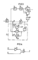
- Fig. 3 ein Ausführungsbeispiel einer Schaltung zur Einzelpulserkennung,
- Fig. 4 die Schaltung der Steuerlogik.
- 1. the known circuit principle of the radar receiver with a pulse length discriminator,
- 2 shows the block diagram of part of the signal evaluation branch with an arrangement for single-pulse detection and control logic,
- 3 shows an embodiment of a circuit for single pulse detection,
- Fig. 4 shows the circuit of the control logic.
Ein Puls-Doppler-Radargerät bekannter Art mit einer Antenne 1 ist eingangsseitig mit einem Sende-Empfangsschalter 2 und einem Sendeoszillator 3 ausgerüstet. Die Umschaltung des Sende-Empfangs-Schalters 2 erfolgt durch einen Taktgenerator 4. Das Eingangssignal gelangt zu einer Mischstufe 5, deren Uberlagerungsoszillator mit 6 bezeichnet ist. Die demodulierten Empfangssignale werden einem Bewegtzeichenfilter 7 (MTI-Filter) zugeführt, das eine größere Anzahl von Entfernungskanälen aufweist. Das Bewegtzeichenfilter unterdrückt Echosignale, die von Festzeichen kommen, während Bewegtzeichen-Echosignale praktisch ungedämpft übertragen werden. Es kann zweckmäßig sein, die Signalbearbeitung in digitaler Form vorzunehmen, d.h. nach der Mischstufe 5 einen hier gestrichelt angedeuteten Analog-Digital-Wandler 8 einzuschalten. Dazu werden einzelne Abtastproben aus dem erhaltenen Signal entnommen, die in digitaler Form weiterverarbeitet werden. Nach Gleichrichtung in einer Anordnung 8 gelangen die so erhaltenen Videosignale an eine Nachintegrationsschaltung 9 und über einen Puls-Längen-Diskriminator 10 mit der Funktion einer Störunterdrückungsschaltung zur Darstellung einer Anzeigeeinrichtung PPI (11) oder sie werden in einer Auswerteeinrichtung weiterverarbeitet. Um auch die Unterdrückung von kurzen störenden Einzelimpulsen zu ermöglichen, muß der Puls-Längen-Diskriminator mit weiteren Schaltungen zusammenarbeiten.A pulse Doppler radar device of a known type with an
In Fig. 2 ist ein um eine Schaltung zur Einzelpulsunterdrückung erweiterter Signalverarbeitungsweg dargestellt. Die wesentlichen Schaltungsteile sind ein steuerbarer Schalter 12, der zwischen dem Puls-Längen-Diskriminator 10 und der Anzeigeeinrichtung 11 so eingefügt ist, daß dieser den Übertragungsweg zur Anzeigeeinrichtung 11 unterbrechen kann und ein am Eingang des Integrators 9 vom Signalverarbeitungsweg abgezweigter Schaltungszweig, der eine weitere Nachintegrationsschaltung 13 und eine Schaltung zur Einzelpulserkennung enthält. Diese Schaltungsteile liefern zusammen mit einer Videoschwelle 19 und einer Steuerlogik 20, die am Ausgang der Einzelpulserkennung 14 liegen, das Kriterium (H- oder L-Signal) für die Betätigung des Schalters 12 bei Vorliegen eines störenden. Einzelpulses. Ein im Pulslängen-Diskriminator 10 nicht unterdrückter Einzelpuls kann nicht an die Anzeigeeinrichtung 11 gelangen, da die Einzelpulserkennung 22 vorher den steuerbaren Schalter 12 geöffnet hat. Das Schaltkriterium wird in der Einzelpulserkennung 22 in der Weise gebildet, daß in jedem Entfernungskanal ständig die Differenz zwischen der Signalamplitude am Ausgang des Gleichrichters 8 und der Signalamplitude am Ausgang der Nachintegrationsschaltung 13 gebildet wird.2 shows a signal processing path expanded by a circuit for single-pulse suppression. The essential circuit parts are a
Ein Ausführungsbeispiel für eine Schaltung zur Einzelpulserkennung wird anhand der Fig. 3 beschrieben. Damit Einzelpulsstörungennicht die Schwelle 19 überschreiten, müssen diese vor der Nachintegration begrenzt oder ausgetastet werden ohne daß Nutzsignalen Energie entzogen wird. Mit der vorliegenden Schaltung geschieht das in der Weise, daß in jedem Entfernungskanal fortwährend die Differenz zwischen der Signalamplitude am Ausgang des Gleichrichters 8 und der Signalamplitude am Ausgang der Nachintegrationsschaltung 13 gebildet wird. Für die Differenzbildung wird der Ausgang des Gleichrichters 8 unmittelbar mit dem Eingang eines Subtrahierers 14 und der Ausgang der Nachintegrationsschaltung 13 über eine Verzögerungsleitung 15 mit einem weiteren Eingang des Subtrahierers 14 verbunden. In einem Komparator 16 wird festgestellt, wann die Differenz am Ausgang des Subtrahierers 14 größer ist als ein fest vorgegebener Wert AA. Dieser Wert wird im Prinzip aus allen dem Radarempfänger angebotenen Signalen,z.B. Zielechos, Störpulsen, Zielechos mit überlagerten Störpulsen als normierter Zielamplitudenwert gebildet, dessen Energie etwa dem kleinsten entdeckbaren Ziel entspricht. Überschreitet der Differenzwert am Ausgang des Subtrahierers den vorgegebenen Wert ΔA, dann liegt ein Störimpuls vor, der den Komparator 17 veranlaßt, ein Signal abzugeben, das den Schalter 18 steuert. Der Eingang der Nachintegrationsschaltung 13 wird vom Gleichrichter 8 getrennt und gleichzeitig verbindet der Schalter 18 Eingang undAn embodiment of a circuit for single pulse detection is described with reference to FIG. 3. So that single pulse disturbances do not exceed the
Ausgang der Nachintegrationsschaltung, so daß eine Rückkopplungsschleife gebildet wird, die außer der Verzögerungsleitung 16 einen Addierer 21 enthält. Der Addierer 21 hat die Aufgabe, auf das rückgekoppelte Ausgangssignal derNachintegration einen Wert ΔA', welcher beispielsweise etwa der normierten Signalamplitude entspricht, aufzuaddieren. Während der Dauer des Störimpulses bildet ein Vorgabewert ΔA" das Eingangssignal der Nachintegrationsschaltung 13, der z.B. dem kleinsten entdeckbaren Bewegtsignal entspricht.Output of the post-integration circuit so that a feedback loop is formed which contains an adder 21 in addition to the
Ist die Amplitudendifferenz der Ausgangssignale von Gleichrichter 8 und Nachintegrationsschaltung 13 wieder kleiner als der vorgegebene Wert ΔA, dann wird die Rückkopplungsschleife mittels des Schalters 18 aufgetrennt und der Ausgang des Gleichrichters 8 mit dem Eingang der Nachintegrationsschaltung 13 verbunden.If the amplitude difference of the output signals from
Der normierte Signalamplitudenwert ΔA, der im Komparator 17 zur Erkennung des Störimpulses führt, muß nicht die gleiche Größe aufweisen, wie der im Addierer 21 auf das um eine Empfangsperiode verzögerte Ausgangssignal der Nachintegrationsschaltung 13 aufaddierte Wert ΔA'. Durch geeignete Kombination der beiden Werte kann mit dem Vorgabewert ΔA" eine optimale Störimpulsunterdrückung geschaffen werden.The normalized signal amplitude value ΔA, which leads to the detection of the interference pulse in the comparator 17, does not have to have the same size as the value ΔA 'added in the adder 21 to the output signal of the
Die Schaltung der Steuerlogik 20 ist in Fig. 4 dargestellt. Die beiden Eingänge E1 und E2 sind an den Ausgang des Pulslängen-Diskriminators 10 und einer Videoschwelle 19 angeschlossen. Das Ausgangssignal des Pulslängen-Diskriminators 10 wird über den Eingang E1 direkt und das Ausgangssignal der Videoschwelle 19 über einen Inverter 24 einem NAND-Gatter 23 zugeführt. Der Ausgang A liefert das Steuersignal für den Schalter 12. Die Funktion der Steuerlogik wird nachfolgend anhand einer Betrachtung von verschiedenen dem Radarempfänger angebotenen Signalen näher erläutert. Dabei werden nacheinander das Echosignal eines Zieles, ein PLD-Störer, ein PLD-Störer mit überlagertem Zielecho und schließlich ein Einzelpuls betrachtet. Man erkennt, daß nur im Fall "Einzelpuls" das Steuersignal "L" generiert wird. In diesem Fall wird der PLD-Weg unterbrochen, die Einzelpulse gelangen somit nicht zur Anzeigeeinrichtung 11.The circuit of the
Claims (6)
Applications Claiming Priority (2)
| Application Number | Priority Date | Filing Date | Title |
|---|---|---|---|
| DE19823222474 DE3222474A1 (en) | 1982-06-15 | 1982-06-15 | PULSE DOPPLER RADAR DEVICE WITH A PULSE LENGTH DISCRIMINATOR |
| DE3222474 | 1982-06-15 |
Publications (3)
| Publication Number | Publication Date |
|---|---|
| EP0096884A2 true EP0096884A2 (en) | 1983-12-28 |
| EP0096884A3 EP0096884A3 (en) | 1984-07-18 |
| EP0096884B1 EP0096884B1 (en) | 1988-11-09 |
Family
ID=6166106
Family Applications (1)
| Application Number | Title | Priority Date | Filing Date |
|---|---|---|---|
| EP19830105790 Expired EP0096884B1 (en) | 1982-06-15 | 1983-06-13 | Pulse doppler radar with a pulse length discriminator |
Country Status (2)
| Country | Link |
|---|---|
| EP (1) | EP0096884B1 (en) |
| DE (1) | DE3222474A1 (en) |
Citations (7)
| Publication number | Priority date | Publication date | Assignee | Title |
|---|---|---|---|---|
| FR1191320A (en) * | 1956-12-20 | 1959-10-19 | Marconi Wireless Telegraph Co | Pulse Radar Improvements |
| US3713153A (en) * | 1969-06-06 | 1973-01-23 | Y Popta | Pulse radar system for detecting moving targets |
| DE2500877A1 (en) * | 1974-01-15 | 1975-07-24 | Ericsson Telefon Ab L M | ARRANGEMENT FOR SUPPRESSING INTERFERRING PULSES IN THE PULSE DOUBLE RADAR |
| DE2537137A1 (en) * | 1975-08-21 | 1977-03-03 | Siemens Ag | Radar receiver with circuit suppressing interfering signals - generates interference-free voltage by control circuit during interference suppression periods |
| US4068233A (en) * | 1976-08-13 | 1978-01-10 | Raytheon Company | Radar system having interference rejection |
| DE2823419A1 (en) * | 1978-05-29 | 1979-12-06 | Siemens Ag | Pulsed Doppler radar receiver system - has noise signal suppression circuit with target threshold amplitude detection and range noise detection |
| EP0073706A1 (en) * | 1981-08-28 | 1983-03-09 | Thomson-Csf | Radar apparatus for eliminating multiple time-around moving echos and clutter echos |
Family Cites Families (7)
| Publication number | Priority date | Publication date | Assignee | Title |
|---|---|---|---|---|
| US3365718A (en) * | 1965-08-31 | 1968-01-23 | Philips Corp | Device for disturbance suppression in a radar equipment |
| GB1291255A (en) * | 1969-01-24 | 1972-10-04 | Marconi Co Ltd | Improvements in or relating to radars |
| US4122452A (en) * | 1974-03-12 | 1978-10-24 | Sanders Associates, Inc. | Jamming signal cancellation system |
| DE2807205C2 (en) * | 1978-02-20 | 1985-04-04 | Siemens AG, 1000 Berlin und 8000 München | Circuit arrangement for achieving a constant false signal rate |
| DE2840938A1 (en) * | 1978-09-20 | 1980-03-27 | Siemens Ag | Pulse doppler radar receiver - has device which forms mean value of interferences and displays them differently from moving targets |
| DE2939512C3 (en) * | 1979-09-28 | 1982-02-25 | Siemens AG, 1000 Berlin und 8000 München | Circuit arrangement for side lobe suppression in radar devices |
| DE3012036C2 (en) * | 1980-03-28 | 1982-06-24 | Siemens AG, 1000 Berlin und 8000 München | Pulse Doppler radar with a CFAR threshold |
-
1982
- 1982-06-15 DE DE19823222474 patent/DE3222474A1/en not_active Withdrawn
-
1983
- 1983-06-13 EP EP19830105790 patent/EP0096884B1/en not_active Expired
Patent Citations (7)
| Publication number | Priority date | Publication date | Assignee | Title |
|---|---|---|---|---|
| FR1191320A (en) * | 1956-12-20 | 1959-10-19 | Marconi Wireless Telegraph Co | Pulse Radar Improvements |
| US3713153A (en) * | 1969-06-06 | 1973-01-23 | Y Popta | Pulse radar system for detecting moving targets |
| DE2500877A1 (en) * | 1974-01-15 | 1975-07-24 | Ericsson Telefon Ab L M | ARRANGEMENT FOR SUPPRESSING INTERFERRING PULSES IN THE PULSE DOUBLE RADAR |
| DE2537137A1 (en) * | 1975-08-21 | 1977-03-03 | Siemens Ag | Radar receiver with circuit suppressing interfering signals - generates interference-free voltage by control circuit during interference suppression periods |
| US4068233A (en) * | 1976-08-13 | 1978-01-10 | Raytheon Company | Radar system having interference rejection |
| DE2823419A1 (en) * | 1978-05-29 | 1979-12-06 | Siemens Ag | Pulsed Doppler radar receiver system - has noise signal suppression circuit with target threshold amplitude detection and range noise detection |
| EP0073706A1 (en) * | 1981-08-28 | 1983-03-09 | Thomson-Csf | Radar apparatus for eliminating multiple time-around moving echos and clutter echos |
Non-Patent Citations (1)
| Title |
|---|
| THE MARCONI REVIEW, Band XXXVI, Nr. 191, 4. Quartal 1973, Seiten 237-248, Great Baddow, GB. * |
Also Published As
| Publication number | Publication date |
|---|---|
| EP0096884B1 (en) | 1988-11-09 |
| DE3222474A1 (en) | 1983-12-15 |
| EP0096884A3 (en) | 1984-07-18 |
Similar Documents
| Publication | Publication Date | Title |
|---|---|---|
| DE3640449C1 (en) | Device for determining the distance between two objects, in particular two motor vehicles | |
| DE2749497C2 (en) | ||
| EP0359911A2 (en) | Radar altimeter | |
| EP0096883B1 (en) | Pulse doppler radar with a pulse length discriminator | |
| DE2546615A1 (en) | FAULT FILTER FOR A PULSE DOPPLER RADAR | |
| DE3041459C2 (en) | ||
| DE602004005453T2 (en) | RADAR ANTIQUE SYSTEMS AND METHODS | |
| EP0096884A2 (en) | Pulse Doppler radar with a pulse length discriminator | |
| DE2157342A1 (en) | Signal processing device, in particular for Doppler radar systems | |
| DE69634188T2 (en) | Radar system | |
| DE2155074C3 (en) | Circuit arrangement for suppressing longer than the useful pulses lasting, in particular wobbled, interference signals for a pulse radar receiver | |
| DE1124103B (en) | Impulse-keyed radar device with suppression of target displays | |
| DE2833023A1 (en) | METHOD AND CIRCUIT FOR DISTANCE MEASUREMENT IN AIRCRAFT USING A TACAN SYSTEM | |
| DE2840938A1 (en) | Pulse doppler radar receiver - has device which forms mean value of interferences and displays them differently from moving targets | |
| DE1591334C1 (en) | Direction-sensitive, distance measuring, non-coherent impulse echo location receiver with fixed-character suppression that can be switched off | |
| DE2325364A1 (en) | ARRANGEMENT FOR DETECTING A WEAK USEFUL SIGNAL IN NOISE OR INTERFERENCE SIGNALS | |
| DE2230823C3 (en) | Pulse Doppler radar with coherent mix | |
| DE2833065C2 (en) | Circuit arrangement for suppressing interfering received signals for a pulse Doppler radar receiver | |
| DE2408595C2 (en) | Device for determining the distance and / or the differential speed between a vehicle and an object | |
| DE2540584A1 (en) | Pulsed doppler radar station with variable pulse frequency - has digital filter with one shift register for scanning sample processing | |
| DE2445417C3 (en) | Impulse radar device with optional Doppler evaluation and a computing device for missile tracking | |
| DE2807205A1 (en) | Interference signal suppression circuit - has filter combining integration between MTI filter and display and following threshold device | |
| DE2500877C3 (en) | Arrangement for suppressing interference pulses in a pulse Doppler radar receiver | |
| DE2641689C2 (en) | Pulse radar device with devices for integrating the received signals | |
| EP0060323A1 (en) | Pulse Doppler radar with variable pulse repetition frequency |
Legal Events
| Date | Code | Title | Description |
|---|---|---|---|
| PUAI | Public reference made under article 153(3) epc to a published international application that has entered the european phase |
Free format text: ORIGINAL CODE: 0009012 |
|
| AK | Designated contracting states |
Designated state(s): FR GB IT NL |
|
| PUAL | Search report despatched |
Free format text: ORIGINAL CODE: 0009013 |
|
| AK | Designated contracting states |
Designated state(s): FR GB IT NL |
|
| 17P | Request for examination filed |
Effective date: 19841221 |
|
| 17Q | First examination report despatched |
Effective date: 19860929 |
|
| D17Q | First examination report despatched (deleted) | ||
| GRAA | (expected) grant |
Free format text: ORIGINAL CODE: 0009210 |
|
| AK | Designated contracting states |
Kind code of ref document: B1 Designated state(s): FR GB IT NL |
|
| GBT | Gb: translation of ep patent filed (gb section 77(6)(a)/1977) | ||
| ET | Fr: translation filed | ||
| ITF | It: translation for a ep patent filed |
Owner name: STUDIO JAUMANN |
|
| PG25 | Lapsed in a contracting state [announced via postgrant information from national office to epo] |
Ref country code: GB Effective date: 19890613 |
|
| PLBE | No opposition filed within time limit |
Free format text: ORIGINAL CODE: 0009261 |
|
| STAA | Information on the status of an ep patent application or granted ep patent |
Free format text: STATUS: NO OPPOSITION FILED WITHIN TIME LIMIT |
|
| 26N | No opposition filed | ||
| PG25 | Lapsed in a contracting state [announced via postgrant information from national office to epo] |
Ref country code: NL Effective date: 19900101 |
|
| GBPC | Gb: european patent ceased through non-payment of renewal fee | ||
| NLV4 | Nl: lapsed or anulled due to non-payment of the annual fee | ||
| PG25 | Lapsed in a contracting state [announced via postgrant information from national office to epo] |
Ref country code: FR Free format text: LAPSE BECAUSE OF NON-PAYMENT OF DUE FEES Effective date: 19900228 |
|
| REG | Reference to a national code |
Ref country code: FR Ref legal event code: ST |