EP0097457A2 - Apparatus for setting a well tool in a well bore - Google Patents
Apparatus for setting a well tool in a well bore Download PDFInfo
- Publication number
- EP0097457A2 EP0097457A2 EP83303337A EP83303337A EP0097457A2 EP 0097457 A2 EP0097457 A2 EP 0097457A2 EP 83303337 A EP83303337 A EP 83303337A EP 83303337 A EP83303337 A EP 83303337A EP 0097457 A2 EP0097457 A2 EP 0097457A2
- Authority
- EP
- European Patent Office
- Prior art keywords
- mandrel
- tool
- tubular portion
- well
- conduit
- Prior art date
- Legal status (The legal status is an assumption and is not a legal conclusion. Google has not performed a legal analysis and makes no representation as to the accuracy of the status listed.)
- Withdrawn
Links
Images

Classifications
-
- E—FIXED CONSTRUCTIONS
- E21—EARTH DRILLING; MINING
- E21B—EARTH DRILLING, e.g. DEEP DRILLING; OBTAINING OIL, GAS, WATER, SOLUBLE OR MELTABLE MATERIALS OR A SLURRY OF MINERALS FROM WELLS
- E21B23/00—Apparatus for displacing, setting, locking, releasing, or removing tools, packers or the like in the boreholes or wells
- E21B23/06—Apparatus for displacing, setting, locking, releasing, or removing tools, packers or the like in the boreholes or wells for setting packers
-
- E—FIXED CONSTRUCTIONS
- E21—EARTH DRILLING; MINING
- E21B—EARTH DRILLING, e.g. DEEP DRILLING; OBTAINING OIL, GAS, WATER, SOLUBLE OR MELTABLE MATERIALS OR A SLURRY OF MINERALS FROM WELLS
- E21B33/00—Sealing or packing boreholes or wells
- E21B33/10—Sealing or packing boreholes or wells in the borehole
- E21B33/12—Packers; Plugs
- E21B33/129—Packers; Plugs with mechanical slips for hooking into the casing
- E21B33/1294—Packers; Plugs with mechanical slips for hooking into the casing characterised by a valve, e.g. a by-pass valve
-
- E—FIXED CONSTRUCTIONS
- E21—EARTH DRILLING; MINING
- E21B—EARTH DRILLING, e.g. DEEP DRILLING; OBTAINING OIL, GAS, WATER, SOLUBLE OR MELTABLE MATERIALS OR A SLURRY OF MINERALS FROM WELLS
- E21B33/00—Sealing or packing boreholes or wells
- E21B33/10—Sealing or packing boreholes or wells in the borehole
- E21B33/12—Packers; Plugs
- E21B33/129—Packers; Plugs with mechanical slips for hooking into the casing
- E21B33/1295—Packers; Plugs with mechanical slips for hooking into the casing actuated by fluid pressure
Abstract
@ Apparatus for setting in a well bore a well tool such as a packer, the well tool having expandable anchor means for anchoring it in a well bore, a conduit to permit flow through the tool, and a slidable valve positioned in the conduit having an open lower position and a closed upper position, the apparatus comprising inner (52, 66, 80) and outer (20, 40, 88) tubular portions telescopically interengaged, with the inner portion receiving a slidable mandrel (186). In use, the tool is connected to the inner sleeve by a shearable tension collar (182), the mandrel passing through the collar and into the tool conduit for engagement with the valve. Annular pistons (58, 76; 185) are provided between the inner and outer sleeves and, preferably, between the mandrel and the inner sleeve. A flapper valve (130) is preferably pivotally attached on one side to the inner sleeve for sealing the top of the mandrel. Pressurization of the inner sleeve via tubing string from which the apparatus is suspended pressurizes the annular spaces beneath the pistons thus forcing the inner sleeve as well as the mandrel upwardly to set the tool. Such upward movement of the inner sleeve breaks a seal at the lower end thereof to permit depressurization of the annular space below the mandrel piston which forces the mandrel downwardly. A lock ring (170) is preferably provided to lock the mandrel in its lower position to permit further operation of the valve with the mandrel.
Description
- This invention relates to apparatus for setting a tool in a well bore and, more particularly, to such apparatus in which the setting of the tool is accomplished with hydraulic pressure.
- It is known to set in a well bore various well tools, in particular packers of the type having a conduit therethrough, and thereafter selectively to connect and disconnect a pipe or tubing string to the packer conduit. The packers normally have elastomeric material disposed about the conduit and have upper and lower slip assemblies positioned above and beneath the packing material. The conduit normally includes a valve having an internal sliding sleeve which is selectively movable between one position permitting fluid flow through the conduit, and another position shutting off such flow.
- In order to set such packers in a well bore, setting tools have been used which include a mandrel for insertion into the packer conduit for opening and closing the sleeve valve, an inner sleeve which supports the mandrel and connects it to the conduit string, and a screw jack device disposed between the inner sleeve and an outer setting sleeve. In use of these setting tools, a string is made up wherein the setting tool is connected by its inner sleeve to a tubing string, a breakable tension sleeve is threadedly engaged between the lower end of the inner sleeve and the upper end of the packer conduit, and the setting tool mandrel extends into the packer conduit to maintain the slidable valve in an open position while the tubing string is lowered into the well. When the desired depth for setting the packer in the casing is reached, the tubing string is rotated a predetermined number of times, which rotation operates the screw jack device, thus forcing the setting sleeve downwardly to set the upper packer slips against the sides of the bore. Tension is applied with the tubing to set the lower slips and break the tension sleeve. This leaves the packe- engaged in the bore and the setting tool suspended on the tubing string thereabove. Thereafter, the mandrel may be stung into the packer conduit for actuating the valve to provide fluid communication between the tubing string and the bore beneath the packer.
- These known setting tools have proved somewhat unsatisfactory in practice partly because of their mechanical complexity and also because of the necessity for substantial amounts of vertical and rotational movement of the pipe or tubing string, and loading of the string, in order to set the packer.
- Tools have also been proposed for setting liner hangers, in which hydraulic pressure is used to effect setting. One such apparatus includes an annular collar disposed about a mandrel which is suspended from a tubing string. A ball is dropped down the tubing string to seal the string beneath the collar. A port connects the tubing string to the annulus between the collar and the mandrel and when the string is pressurized, the collar moves upwardly. Setting slips disposed on an inclined surface are suspended from the collar and upward movement along the surface urges the slip outwardly to set the hanger. Such past liner hangers are not adaptable for setting packers of the type above described and do not include a mandrel for actuation of the sliding packer valve.
- We have now devised a tool which is particularly useful for setting packers of the type described in a well bore, and which uses hydraulic pressure to effect setting.
- According to the present invention, there is provided apparatus for setting in a well bore a well tool which tool includes expandable anchor means and a central conduit including a slidable conduit valve for selectively permitting fluid flow through the conduit, wherein said apparatus comprises a first tubular portion; a second tubular portion telescopically received within said first tubular portion; a coupling mounted on the outer end of said first tubular portion, for rigidly connecting said first portion to a string of tubing; piston means disposed between said portions, said piston means being arranged to force said second portion outwardly from said first portion in response to fluid pressure; shearable means mounted on the outer end of said second portion, for supporting a well tool therefrom; and a mandrel slidably engaged within said second portion and arranged to extend (in use) into the tool conduit to maintain said slidable valve in a fluid-flow condition when the well tool has been set in the well bore.
- In preferred embodiments of the present invention, the apparatus comprises inner and outer sleeves telescopically interengaged and adapted to be suspended from a pipe or tubing string for lowering into a well bore; and a shearable tension sleeve connecting a packer of the above-described type to the lower end of the inner sleeve. A vertically shiftable mandrel is received within the inner sleeve for engaging the packer valve. Piston means are disposed between the inner and outer sleeves and between the mandrel and the inner sleeve. Pressurization of the tubing acts on the piston means to effect upward movement of the inner sleeve and of the mandrel. Such pressurization seals the top of the mandrel from the tubing string by means of a flapper valve. When the inner sleeve assumes a predetermined position with respect to the outer sleeve pressure beneath the mandrel piston means is automatically released, thus permitting downward mandrel movement with respect to the inner sleeve. Mandrel lock means are preferably included to lock the mandrel to the inner sleeve to permit selective actuation of the packer valve by raising and lowering the tubing string.
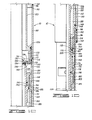
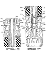
- In order that the invention may be more fully understood, one embodiment thereof will now be described, by way of example only, with reference to the accompanying drawings, wherein:
- FIGURES 1A-1F are successive downward continuations, shown partly in quarter-section and partly in half-section, of the embodiment of setting tool shown attached to a packer.
- Referring to the drawings, indicated generally at 10 is a setting tool constructed in accordance with the present invention. A well tool or
packer 12 is mounted on the lower end of the setting tool. Anadapter mandrel 14 is substantially cylindrically shaped and includesthreads 16 for threadably engaging the setting tool and packer combination to an adapter of a tubing string (although a string of drill pipe will work equally well) for lowering into a well bore. As will be explained in detail herein, settingtool 10 is constructed to setpacker 12 in a well bore responsive to pressurization of the tubing string. Thereafter, the tool may be lowered onto the packer, as desired, to provide fluid communication between the well bore beneath the packer and the tubing string. -
Adapter mandrel 14 includes a second set ofthreads 18 at - The lower end of
piston case 40 is threadably engaged viathreads 46 with a lower annular joiningnipple 48. Nipple 48 is substantially identical to joining nipple 26 and includes anannular ring 50like ring 34 in nipple 26. -
Adapter mandrel 14,coupling 19,piston case 20, joining nipple 26,piston case 40, and joiningnipple 48, all comprise the upper portion of what is referred to herein as a first tubular portion. These components provide a generally cylindrical outer sleeve which is attached viaadapter mandrel 14 to the tubing string adapter. - Description will now be made of components which make up the upper part of what is referred to herein as a second tubular portion. The second tubular portion includes an
upper sleeve 52, such being cylindrically shaped and further being in sealing engagement, via an 0-ring 54, with the lower radially inner surface ofcoupling 19. The lower end ofupper sleeve 52 includes a wideneddiameter portion 56 such being in threaded engagement with anupper piston 58 viathreads 60. - The upper piston is generally annularly shaped and includes an 0-
ring 62 for sealing the radially outer surface of the piston to the radially inner surface ofpiston case 20.Threads 64 formed about the lower portion ofupper piston 58 engage the piston to amiddle sleeve 66. - The middle sleeve includes a
bore 68. Bore 68 provides fluid communication between the interior ofmiddle sleeve 66 and anannular chamber 69 formed between upper joiningnipple 26 andupper piston 58. Aset screw 70 is received within a threaded bore inupper piston 58 and abuts against the radially outer surface ofmiddle sleeve 66 to fix the position of the upper piston with respect to the middle sleeve. -
Middle sleeve 66 includes at its lower end a wideneddiameter portion 72 includingthreads 74 for engaging alower piston 76. - The lower piston is substantially identical to
piston 58. The lower piston is threadably engaged viathreads 78 to alower sleeve 80. The upper and lower pistons are referred to herein as piston means.Lower sleeve 80 includes abore 82 formed between its interior and exterior surfaces. Bore 82 provides fluid communication between the interior of sleeve 80 (and hence the tubing string connected to adapter mandrel 14) and anannular chamber 84 formed betweenlower nipple 48 andlower piston 76. - Lower joining
nipple 48 is threadably engaged viathreads 86 with a substantially cylindricalsetting sleeve body 88. The setting sleeve body includes a-bore 90 between its interior and exterior, such being formed beneaththreads 86. Settingsleeve 88 also includes anannular ridge 92 formed about the radially inner surface of the setting sleeve body. The annular ridge includes a substantiallycylindrical surface 94 formed at the top of the ridge about the circumference thereof. The lower end of settingsleeve body 88 includesthreads 96 and an O-ring 98 for sealingly connecting the setting sleeve body to a substantially cylindrical setting sleeve 100. Aset screw 102 is received within a threaded bore formed through the setting sleeve body beneaththreads 96. The set screw abuts against the radially outer surface of setting sleeve 100 to fix the relative positions of the setting sleeve body and the setting sleeve. - Setting sleeve 100 includes an
annular chamfer 104 formed about the circumference of the setting sleeve at its lower end.Chamfer 104 is referred to herein as anchor engagement means. - The above-described upper portion of the first tubular assembly (shown in FIGS. 1A and 18) continues downwardly to include setting
sleeve body 88 and setting sleeve 100. Thus, the first tubular portion, beginning withcoupling 19 andupper piston case 20 and extending downwardly to setting sleeve 100, is substantially cylindrical and is fixedly mounted on the tubing string (not shown) viaadapter mandrel 14. - What is referred to herein as a second tubular portion includes at its upper end,
upper sleeve 52 and extends downwardly to includemiddle sleeve 66 andlower sleeve 80. Continuing the description of the second tubular portion, in FIG. IC, the lower end oflower sleeve 80 includes a wideneddiameter portion 106.Portion 106 includes acounterbore 108 which provides fluid communication between the interior ofsleeve 80 and its exterior at the lower end thereof.Threads 110 provide threaded engagement betweenportion 106 of the lower sleeve and aflapper valve housing 112. - The flapper valve housing includes an annular
upper portion 114.Portion 114 includes acircular bore 116, such being of the same diameter ascounterbore 108 and communicating therewith. Avertical slot 118 is formed on one side ofbore 116. Abore 120 is formed betweenslot 118 and the radially outer surface ofupper portion 114. A lowerannular portion 122 offlapper valve housing 112 includes acircular bore 124 which permits fluid communication between a radiallyinner portion 126 of settingsleeve body 88 and the interior of the flapper valve housing. The surface ofbore 124 is denoted bynumeral 128. - A
flapper valve 130 includes acircular valve body 132. Anannular seal 134 is mounted on the lower side ofvalve body 132. A mounting tab 136 extends from the rear end ofvalve body 132 and is received withinslot 118. The mounting tab includes a hole through which apost 138 extends.Post 138 is fixedly received within bores (not shown) formed on either side ofcircular bore 116. Thus,flapper valve 130 pivots aboutpost 138. Aspring 140 biases the flapper valve downwardly. - A
mandrel case 142 is substantially cylindrically shaped and is threadably engaged with the lower end of the flapper valve housing viathreads 144.Mandrel case 142 includes anannular channel 146 formed in the radially outer surface of the mandrel case about its circumference. An O-ring 148 is received within the channel. Anannular space 150 is formed betweenmandrel case 142 and settingsleeve body 88. Anotherannular space 152 is formed between the mandrel case and setting sleeve 100.Spaces mandrel case 142 includes acounterbore 154. The lower end is threadably engaged viathreads 156 to alock ring housing 158. - The lock ring housing is of annular shape and includes an annular upward facing
shoulder 160 about the interior of the housing. Anannular space 162 is formed between the radially outer surface oflock ring housing 158 and the radially inner surface of setting sleeve 100. An O-ring 164, also referred to herein as sealing means, provides a seal between the lock ring housing and the radially inner surface of the setting sleeve at the lower end ofspace 162. Abore 166 provides fluid communication betweenspace 162 and the interior oflock ring housing 158. - A
lock ring 168, also referred to herein as mandrel lock means, includes a plurality of arcuate segments, one of which issegment 170. The segments are constrained from vertical movement between the lower end ofmandrel case 142 andshoulder 160 on the lock ring housing. The segments are all biased radially inwardly by an 0-ring 172 disposed about the radially outer side of the segments. - A
coupling ring support 174 is generally cylindrically shaped and is threadably engaged viathreads 176 to the lower end oflock ring housing 158.Support 174 includes an annularupper end 159. The coupling ring support includes an upward facingshoulder 178 for maintaining acoupling ring 180 betweenshoulder 178 and the lower end oflock ring housing 158. The coupling ring is attached to a generally cylindrically shapedtension sleeve 182, also referred to herein as shearable means, viathreads 183. -
Tension sleeve 182 provides a connection between settingtool 10 andpacker 12. The lower end oftension sleeve 182 is threadably engaged to a generally cylindrical conduit orpacker mandrel 184 substantially contained within the packer. The setting tool includes amandrel 186, which extends from just beneathflapper valve 130 intopacker mandrel 184. The mandrel is generally cylindrically shaped and has its top end sealed againstannular seal 134 of the flapper valve. An O-ring 188 provides sealing engagement between the radially outer surface of the mandrel and the radially inner surface offlapper valve housing 112. An annular piston orcollar 185 is formed about the radially outer circumference of the mandrel. A second O-ring 190 seals the collar between its radially outer surface and the radially inner surface ofmandrel case 142. An annularhydraulic chamber 189 is formed beneathcollar 185. The top ofcollar 185 includes an upward facingannular shoulder 192. Abore 194 is formed through the mandrel to provide fluid communication between the mandrel interior and exterior. The mandrel includes anannular portion 195 having an upward facingshoulder 196 in FIG. 1D.Shoulder 196 is annular in shape and is formed about the circumference of the mandrel. An O-ring 198 seals the mandrel about its circumference between the radially outer surface of the mandrel and the radially inner surface ofcoupling ring support 174. At its lower end,mandrel 186 includes a reduceddiameter portion 200 and at the very lower end of the mandrel, anannular chamfer 202. -
Packer 12 includes aconventional split ring 204 which, in the condition shown in FIG. 1E, maintainsslips slips lock ring housing 207. Aconventional wedge 208 is provided to forceslips Elastomeric packers 212 are confined aboutpacker mandrel 184 betweenupper wedge 208 and alower wedge 214. The lower wedge coacts with slips such aslower slips - A cylindrical sliding
valve sleeve 222 is closely received within the lower end ofpacker mandrel 184. The valve sleeve includes a pair ofports ports packer mandrel 184.Valve sleeve 222 includes upwardly extendingfingers diameter portion 200 ofmandrel 186. Fingers such asfingers shoulders annular shoulder 240 onmandrel 186 defines the lower end of reduceddiameter portion 200. Anannular groove 242 is formed about the radially inner surface ofpacker mandrel 184 abovefingers - In operation,
tool 10 andpacker 12 are connected to a tubing string viaadapter mandrel 14 at the surface of a well bore. The tool and the packer are in the configuration as shown in FIGS. lA-1F.Mandrel 186 is in its upperposition having shoulder 192 abutted against the lower end offlapper valve housing 112. The lower end of the flapper valve housing prevents the mandrel from moving any further upwardly.Annular shoulder 202 at the lower end ofmandrel 186 is pressed against slidingvalve 222 to maintain the valve in its lowermost position thus aligningports ports lower slips - As the tubing string is lowered into the well bore, fluid enters the packer and setting tool via
ports ports mandrel 186 and forces flappervalve 130 upwardly off the top of the stinger to permit filling of the tubing. - When the depth is reached at which it is desired to set the packer in the well bore, lowering of the tubing is stopped. At this point, the fluid in the tubing is pressurized by applying pump pressure to the tubing at the top of the well bore. As the fluid pressure in the tubing increases, fluid is pumped into
chambers bores upper piston 58 and onlower piston 76 causes upward movement of the second tubular portion, such includingupper sleeve 52,middle sleeve 66,lower sleeve 80,flapper valve housing 112,mandrel case 142,lock ring housing 158,coupling ring support 174, andcoupling ring 180. It is noted that upward movement ofcoupling ring 180 likewise movestension ring 182 upwardly and hence the packer, to which the tension ring is attached. As application of fluid pressure continues, the packer moves upwardly so thatchamfer 104 on the lower end of setting sleeve 100 engageslock ring 204 on the packer.chamfer 104 descends into the radially inner side of the lock ring, thus causing spreading of the ring to permit the setting sleeve to pushlock ring housing 207 and hence slips 204, 206 downwardly. Such downward motion causes engagement ofslips lower slips lower wedge 214, thus forcinglower slips Packer 12 is at this point set in the well bore. - During such upward movement of the second or inner tubular portion,
mandrel 186 is maintained in its upper position by fluid pressure from the tubing communicated tohydraulic chamber 189 beneathmandrel collar 185 as follows: fluid flows from the tubing throughinner sleeve 80,counterbore 108,slot 118 and bore 124 to the annular space betweenlower portion 122 of the flapper valve housing and settingsleeve body 88. From there, fluid passes downwardly toannular space 150 since there are no 0-rings or other seals to prevent transmission of fluid pressure frombore 124 toannular space 150. As will be recalled,annular space 150 communicates withspace 152 which in turn communicates withannular space 162. Bore 166 permits pressure transmission to the interior of the lock ring housing and from thence upwardly throughcounterbore 154 intohydraulic chamber 189. It will be seen that when the hydraulic chamber is pressurized, such pressure acts to forcemandrel collar 185 upwardly to maintain it against the lower part offlapper valve housing 112. - Continued pressurization after setting of the upper and lower slips causes further upward movement of the second tubular portion and
mandrel 186. It can be seen that the interior ofmandrel 186 is not pressurized due to the sealing of the flapper valve over the top of the mandrel. Continued pressurization ultimately breakstension sleeve 182 thus separating the tool from the packer. During upward movement of the second tubular portion and ofmandrel 186, slidingvalve 222 is lifted upwardly whenshoulder 240 on the mandrel engagesshoulders annular groove 242, thus locking the valve in its upper closed position. Continued upward movement ofmandrel 186 lifts the mandrel away from the fingers leaving the valve locked in its closed position. - As
mandrel case 142 moves upwardly, O-ring 148 ultimately seals againstsurface 94 onridge 92. Thus, the pressurized fluid inhydraulic chamber 189 is sealed off from the pressurized fluid in the tubing. Immediately after sealing of 0-ring 148 againstsurface 94, continued pressurization of the tubing string lifts the first tubular portion enough to raiseseal 164 above the top of setting sleeve 100. This breaks the seal between the pressurized fluid inhydraulic chamber 189 and the fluid in the well bore. The pressurized fluid in the hydraulic chamber passes from the chamber throughbore 166 andannular space 162 into the bore fluid (since O-ring 164 is no longer sealingly engaged against the radially inner surface of setting sleeve 100). - Such depressurization of the hydraulic chamber permits downward movement of
mandrel 186. The pressurized fluid in the tubing (and in counterbore 108) applies downward pressure to the top offlapper valve 130. Oncehydraulic chamber 189 is depressurized, the downward acting pressure on the flapper valve causesmandrel 186 to begin downward movement. Once the seal between the top of the mandrel andseal 134 in the flapper valve is broken, pressurized fluid from the tubing may entermandrel 186. When such fluid enters the mandrel, it is transmitted viabore 194 to the annular space abovemandrel collar 185 thus further forcing the mandrel downwardly. Downward movement of the mandrel continues untilshoulder 196passes locking ring 170. Further downward movement of the mandrel is prevented by engagement ofannular portion 195 withshoulder 159.Lock ring 168 acting againstshoulder 196 prevents upward movement of the stinger. Thus, the mandrel is substantially locked in its lower position. - As
mandrel 186 moves downwardly,chamfer 202 at the lower end of the mandrel abuts against slidingvalve 222 to move it from its upper closed position back to its lower open position as shown in FIG. 1F. Thus, the packer is set in the well, the tension sleeve connecting the packer totool 10 is broken,mandrel 186 is locked in its lower position, and slidingvalve 222 is in its lowermost open position. Operations as desired may proceed, e.g., fluid may be withdrawn from the bore beneath the packer and/or fluid injected.into the bore beneath the packer. Thereafter, if it is desired to seal off the bore beneath the packer, the tubing string is raised thus liftingmandrel 186 and hence moving slidingvalve 222 to its upper closed position. If it is desired to again open the valve, the tubing string may again be lowered thus abutting the lower end ofmandrel 186 against the sliding valve to open it for further operations.
Claims (10)
1. Apparatus for setting in a well bore a well tool which tool includes expandable anchor means and a central conduit including a slidable conduit valve for selectively permitting fluid flow through the conduit, wherein said apparatus comprises a first tubular portion (20,40,88); a second tubular portion (52,66,80) telescopically received within said first tubular portion; a coupling mounted (14) on the outer end of said first tubular portion, for rigidly connecting said first portion to a string of tubing; piston means (58,76) disposed between said portions, said piston means being arranged to force said second portion outwardly from said first portion in response to fluid pressure; shearable means (182) mounted on the outer end of said second portion, for supporting a well tool therefrom; and a mandrel (186) slidably engaged within said second portion and arranged to extend (in use) into the tool conduit to maintain said slidable valve in a fluid-flow condition when the well tool has been set in the well bore.
2. Apparatus according to claim 1, which further includes anchor engagement means (104) mounted on the lower end of said first tubular portion for engagement (in use) with the expandable anchor means on the well tool to cause expansion of the anchor means and anchoring of the tool.
3. Apparatus according to claim 1 or 2, which further includes means (185,112; 195,159) for limiting the upper and lower position of said mandrel relative to said second tubular portion.
4. Apparatus according to claim 1,2 or 3, wherein said mandrel includes a longitudinal bore therethrough and said apparatus further includes mandrel piston means (185) mounted on said mandrel and flapper valve means (130) pivotally mounted on said second tubular portion for covering and sealing the top of said mandrel.
5. Apparatus according to claims 3 and 4, further including conduit means (118,124,150,152,162,166,154) disposed between said second tubular portion above said flapper valve and the exterior of said mandrel beneath said mandrel piston means so that (in use) fluid pressurization of the tubing urges said mandrel upwardly to its upper limit and urges said flapper valve means downwardly for sealing the mandrel interior from the tubing.
6. Apparatus according to claim 4 or 5, which further includes a bore (194) formed in said mandrel to permit fluid communication between said mandrel and the exterior of said mandrel above said mandrel piston means.
7. Apparatus according to claim 4,5 or 6, which further includes sealing means (164) formed between said first and second portions at the lower end of said first portion for providing fluid communication between the area beneath said mandrel piston means and the well bore when said second tubular portion reaches a predetermined longitudinal position with respect to said first tubular portion.
8. Apparatus according to claim 11, wherein said apparatus further includes means (195,159; 168,196) for locking said mandrel to said second tubular portion when said mandrel assumes a predetermined longitudinal position relative to said second tubular portion.
9. Apparatus according to any preceding claim for locking a packer in a well bore.
10. Apparatus according to claim 9, which further includes a packer (12) mounted on said shearable means.
Applications Claiming Priority (2)
| Application Number | Priority Date | Filing Date | Title |
|---|---|---|---|
| US389592 | 1982-06-18 | ||
| US06/389,592 US4441552A (en) | 1982-06-18 | 1982-06-18 | Hydraulic setting tool with flapper valve |
Publications (2)
| Publication Number | Publication Date |
|---|---|
| EP0097457A2 true EP0097457A2 (en) | 1984-01-04 |
| EP0097457A3 EP0097457A3 (en) | 1986-02-12 |
Family
ID=23538893
Family Applications (1)
| Application Number | Title | Priority Date | Filing Date |
|---|---|---|---|
| EP83303337A Withdrawn EP0097457A3 (en) | 1982-06-18 | 1983-06-09 | Apparatus for setting a well tool in a well bore |
Country Status (4)
| Country | Link |
|---|---|
| US (1) | US4441552A (en) |
| EP (1) | EP0097457A3 (en) |
| AU (1) | AU555873B2 (en) |
| CA (1) | CA1187407A (en) |
Cited By (2)
| Publication number | Priority date | Publication date | Assignee | Title |
|---|---|---|---|---|
| CN103046917A (en) * | 2013-01-22 | 2013-04-17 | 中国石油天然气股份有限公司 | Underground electric hydraulic control fracturing sliding sleeve |
| CN108086938A (en) * | 2016-11-21 | 2018-05-29 | 中国石油化工股份有限公司 | A kind of packer |
Families Citing this family (21)
| Publication number | Priority date | Publication date | Assignee | Title |
|---|---|---|---|---|
| US4708202A (en) * | 1984-05-17 | 1987-11-24 | The Western Company Of North America | Drillable well-fluid flow control tool |
| US4583593A (en) * | 1985-02-20 | 1986-04-22 | Halliburton Company | Hydraulically activated liner setting device |
| US4765404A (en) * | 1987-04-13 | 1988-08-23 | Drilex Systems, Inc. | Whipstock packer assembly |
| US4773478A (en) * | 1987-05-27 | 1988-09-27 | Halliburton Company | Hydraulic setting tool |
| US4823881A (en) * | 1988-02-11 | 1989-04-25 | Halliburton Company | Hydraulic setting tool |
| US5146983A (en) * | 1991-03-15 | 1992-09-15 | Schlumberger Technology Corporation | Hydrostatic setting tool including a selectively operable apparatus initially blocking an orifice disposed between two chambers and opening in response to a signal |
| US5305828A (en) * | 1993-04-26 | 1994-04-26 | Halliburton Company | Combination packer/safety valve assembly for gas storage wells |
| US5404956A (en) * | 1993-05-07 | 1995-04-11 | Halliburton Company | Hydraulic setting tool and method of use |
| US5564502A (en) * | 1994-07-12 | 1996-10-15 | Halliburton Company | Well completion system with flapper control valve |
| US5826652A (en) * | 1997-04-08 | 1998-10-27 | Baker Hughes Incorporated | Hydraulic setting tool |
| US6997252B2 (en) * | 2003-09-11 | 2006-02-14 | Halliburton Energy Services, Inc. | Hydraulic setting tool for packers |
| US7708080B2 (en) * | 2005-06-23 | 2010-05-04 | Schlumberger Technology Corporation | Packer |
| US7762323B2 (en) * | 2006-09-25 | 2010-07-27 | W. Lynn Frazier | Composite cement retainer |
| GB2460474B (en) * | 2008-05-31 | 2012-02-29 | Red Spider Technology Ltd | Large bore packer |
| US8479809B2 (en) * | 2010-11-30 | 2013-07-09 | Baker Hughes Incorporated | Anti-extrusion backup system, packing element system having backup system, and method |
| US9255461B2 (en) * | 2012-08-17 | 2016-02-09 | Baker Hughes Incorporated | Removable fracturing plug of particulate material housed in a sheath set by expansion of a passage through the sheath |
| US20140338887A1 (en) * | 2013-05-17 | 2014-11-20 | Gerald Bullard | Annular fluid containment device |
| CN106837227B (en) * | 2017-03-27 | 2023-07-04 | 成都市中油石油钻采物资有限公司 | Underground static pressure energy cable setting tool |
| US10443345B2 (en) * | 2017-05-01 | 2019-10-15 | Comitt Well Solutions LLC | Methods and systems for a complementary valve |
| CN108071358B (en) * | 2018-01-03 | 2024-03-12 | 中国石油天然气集团有限公司 | Electric hydraulic three-stage piston packer feeding device |
| CN116291299B (en) * | 2023-03-16 | 2023-11-17 | 河海大学 | Rapidly-rebounded compression type oil cylinder packer and packer sealing method |
Citations (5)
| Publication number | Priority date | Publication date | Assignee | Title |
|---|---|---|---|---|
| US3299955A (en) * | 1964-01-17 | 1967-01-24 | John S Page Sr | Well tool apparatus |
| US3306366A (en) * | 1964-04-22 | 1967-02-28 | Baker Oil Tools Inc | Well packer apparatus |
| US3498376A (en) * | 1966-12-29 | 1970-03-03 | Phillip S Sizer | Well apparatus and setting tool |
| US3556220A (en) * | 1969-04-01 | 1971-01-19 | Otis Eng Co | Well tools |
| US4253521A (en) * | 1978-10-23 | 1981-03-03 | Halliburton Company | Setting tool |
Family Cites Families (6)
| Publication number | Priority date | Publication date | Assignee | Title |
|---|---|---|---|---|
| US3122205A (en) * | 1960-11-14 | 1964-02-25 | Brown Oil Tools | Well packer assemblies |
| US3306363A (en) * | 1964-04-22 | 1967-02-28 | Baker Oil Tools Inc | Valve controlled well packer apparatus |
| US3298437A (en) * | 1964-08-19 | 1967-01-17 | Martin B Conrad | Actuator device for well tool |
| US3356140A (en) * | 1965-07-13 | 1967-12-05 | Gearhart Owen Inc | Subsurface well bore fluid flow control apparatus |
| US3608634A (en) * | 1970-03-19 | 1971-09-28 | Brown Oil Tools | Hydraulic set liner hanger |
| US3735827A (en) * | 1972-03-15 | 1973-05-29 | Baker Oil Tools Inc | Down-hole adjustable hydraulic fishing jar |
-
1982
- 1982-06-18 US US06/389,592 patent/US4441552A/en not_active Expired - Fee Related
-
1983
- 1983-06-08 AU AU15490/83A patent/AU555873B2/en not_active Ceased
- 1983-06-09 EP EP83303337A patent/EP0097457A3/en not_active Withdrawn
- 1983-06-15 CA CA000430465A patent/CA1187407A/en not_active Expired
Patent Citations (5)
| Publication number | Priority date | Publication date | Assignee | Title |
|---|---|---|---|---|
| US3299955A (en) * | 1964-01-17 | 1967-01-24 | John S Page Sr | Well tool apparatus |
| US3306366A (en) * | 1964-04-22 | 1967-02-28 | Baker Oil Tools Inc | Well packer apparatus |
| US3498376A (en) * | 1966-12-29 | 1970-03-03 | Phillip S Sizer | Well apparatus and setting tool |
| US3556220A (en) * | 1969-04-01 | 1971-01-19 | Otis Eng Co | Well tools |
| US4253521A (en) * | 1978-10-23 | 1981-03-03 | Halliburton Company | Setting tool |
Cited By (4)
| Publication number | Priority date | Publication date | Assignee | Title |
|---|---|---|---|---|
| CN103046917A (en) * | 2013-01-22 | 2013-04-17 | 中国石油天然气股份有限公司 | Underground electric hydraulic control fracturing sliding sleeve |
| CN103046917B (en) * | 2013-01-22 | 2015-09-09 | 中国石油天然气股份有限公司 | A kind of down-hole electrichydraulic control fracturing sliding bush |
| CN108086938A (en) * | 2016-11-21 | 2018-05-29 | 中国石油化工股份有限公司 | A kind of packer |
| CN108086938B (en) * | 2016-11-21 | 2020-03-31 | 中国石油化工股份有限公司 | Packer |
Also Published As
| Publication number | Publication date |
|---|---|
| CA1187407A (en) | 1985-05-21 |
| EP0097457A3 (en) | 1986-02-12 |
| US4441552A (en) | 1984-04-10 |
| AU1549083A (en) | 1983-12-22 |
| AU555873B2 (en) | 1986-10-16 |
Similar Documents
| Publication | Publication Date | Title |
|---|---|---|
| US4441552A (en) | Hydraulic setting tool with flapper valve | |
| US5277253A (en) | Hydraulic set casing packer | |
| US4516634A (en) | Hydraulic running and setting tool for well packer | |
| US5058684A (en) | Drill pipe bridge plug | |
| EP0088550B1 (en) | Tester valve with liquid spring | |
| US3948322A (en) | Multiple stage cementing tool with inflation packer and methods of use | |
| US4105069A (en) | Gravel pack liner assembly and selective opening sleeve positioner assembly for use therewith | |
| US5178219A (en) | Method and apparatus for performing a block squeeze cementing job | |
| US5279370A (en) | Mechanical cementing packer collar | |
| US4311194A (en) | Liner hanger and running and setting tool | |
| US5404956A (en) | Hydraulic setting tool and method of use | |
| US4444268A (en) | Tester valve with silicone liquid spring | |
| US5038862A (en) | External sleeve cementing tool | |
| EP0697496A2 (en) | High pressure well cementing plug assembly | |
| EP0606981A1 (en) | Downhole valve apparatus | |
| EP0496540A1 (en) | Downhole inflatable packing apparatus | |
| US4662446A (en) | Liner seal and method of use | |
| US4618000A (en) | Pump open safety valve and method of use | |
| US4619325A (en) | Well surging method and system | |
| US4576235A (en) | Downhole relief valve | |
| US4436149A (en) | Hydraulic setting tool | |
| EP0328327B1 (en) | Hydraulic setting tool | |
| CA2723012C (en) | Apparatus and method for drilling a wellbore with casing and cementing the casing in the wellbore | |
| US3361209A (en) | Well packer | |
| US4421172A (en) | Drill pipe tester and safety valve |
Legal Events
| Date | Code | Title | Description |
|---|---|---|---|
| PUAI | Public reference made under article 153(3) epc to a published international application that has entered the european phase |
Free format text: ORIGINAL CODE: 0009012 |
|
| AK | Designated contracting states |
Designated state(s): DE FR GB NL |
|
| PUAL | Search report despatched |
Free format text: ORIGINAL CODE: 0009013 |
|
| AK | Designated contracting states |
Designated state(s): DE FR GB NL |
|
| 17P | Request for examination filed |
Effective date: 19860122 |
|
| 17Q | First examination report despatched |
Effective date: 19870623 |
|
| STAA | Information on the status of an ep patent application or granted ep patent |
Free format text: STATUS: THE APPLICATION IS DEEMED TO BE WITHDRAWN |
|
| 18D | Application deemed to be withdrawn |
Effective date: 19870703 |
|
| RIN1 | Information on inventor provided before grant (corrected) |
Inventor name: HAMMAN, REED KEVIN |