EP0098100A2 - Flexible tube for an endoscope - Google Patents
Flexible tube for an endoscope Download PDFInfo
- Publication number
- EP0098100A2 EP0098100A2 EP83303614A EP83303614A EP0098100A2 EP 0098100 A2 EP0098100 A2 EP 0098100A2 EP 83303614 A EP83303614 A EP 83303614A EP 83303614 A EP83303614 A EP 83303614A EP 0098100 A2 EP0098100 A2 EP 0098100A2
- Authority
- EP
- European Patent Office
- Prior art keywords
- braid
- metallic
- sheath
- fibres
- flexible tube
- Prior art date
- Legal status (The legal status is an assumption and is not a legal conclusion. Google has not performed a legal analysis and makes no representation as to the accuracy of the status listed.)
- Granted
Links
Images

Classifications
-
- A—HUMAN NECESSITIES
- A61—MEDICAL OR VETERINARY SCIENCE; HYGIENE
- A61B—DIAGNOSIS; SURGERY; IDENTIFICATION
- A61B1/00—Instruments for performing medical examinations of the interior of cavities or tubes of the body by visual or photographical inspection, e.g. endoscopes; Illuminating arrangements therefor
- A61B1/00064—Constructional details of the endoscope body
- A61B1/00071—Insertion part of the endoscope body
-
- A—HUMAN NECESSITIES
- A61—MEDICAL OR VETERINARY SCIENCE; HYGIENE
- A61B—DIAGNOSIS; SURGERY; IDENTIFICATION
- A61B1/00—Instruments for performing medical examinations of the interior of cavities or tubes of the body by visual or photographical inspection, e.g. endoscopes; Illuminating arrangements therefor
- A61B1/005—Flexible endoscopes
- A61B1/0051—Flexible endoscopes with controlled bending of insertion part
- A61B1/0055—Constructional details of insertion parts, e.g. vertebral elements
-
- A—HUMAN NECESSITIES
- A61—MEDICAL OR VETERINARY SCIENCE; HYGIENE
- A61M—DEVICES FOR INTRODUCING MEDIA INTO, OR ONTO, THE BODY; DEVICES FOR TRANSDUCING BODY MEDIA OR FOR TAKING MEDIA FROM THE BODY; DEVICES FOR PRODUCING OR ENDING SLEEP OR STUPOR
- A61M25/00—Catheters; Hollow probes
- A61M25/0043—Catheters; Hollow probes characterised by structural features
- A61M25/005—Catheters; Hollow probes characterised by structural features with embedded materials for reinforcement, e.g. wires, coils, braids
Definitions
- the present invention relates to an endoscope.
- An endoscope is generally formed of a forward end portion having an objective lens, a control body having an eyepiece, a bendable portion and flexible tube connected between the forward end portion and the control body.
- the insert portion i.e., the forward end portion, the bendable portion and the flexible tube are inserted in the cavity of a human body, and the bendable portion is bent and operated by the control body to perform desired observations and/or operations.
- the flexible tube has as an innermost layer a tubular core formed by a helically wound metallic strip to prevent collapsing of the tube.
- a cylindrical braid envelopes the core to prevent the flexible tube from twisting, and a sheath formed by, e.g., a plastic tube, covers the braid. The sheath is heated to melt a portion thereof into the interstices of the cylindrical braid to secure the sheath to the braid. Alternatively, a suitable adhesive can be inserted between the sheath and the braid to secure them to each other.
- ring-like end pieces are integrally mounted by brazing.
- a conventional cylindrical braid for the flexible tube of such an endoscope is formed by a network of metallic wires.
- US-A-3,691,001 discloses that, to improve the bonding strength between a sheath and a braid which is fitted snugly about an optical fibre bundle, the braid may be formed by interwoven metallic fibres and non-metallic fibres of natural and/or synthetic fibres, e.g., silk, cotton or polyamide.
- ⁇ An object of the present invention is to overcome the above-mentioned disadvantage and to provide a flexible tube for an endoscope having strong bonding strength between the sheath and the cylindrical braid and also having strong securing strength between the braid and the end pieces.
- a flexible -tube for an endoscope having a tubular core made from helically wound metallic strip, a cylindrical braid member fitted over the core, a metallic annular end piece secured to each end of the core and the braid member and a plastics sheath secured to the outer surface of the braid member is characterised in that the braid is made of metallic wires and heat-resistant, chemicals-resistant non-metallic filaments and/or fibres.
- the sheath is secured very strongly to the non-metallic fibres of the braid, and the end pieces can be soldered to the metallic wires of the braid without affecting the non-metallic filaments or fibres by heat and soldering flux.
- an endoscope 1 has a forward end portion 2, a bendable portion 3, a flexible tube 4 and a control body 5 which has an eyepiece 6 and an operating knob 6 1 for controlling bending of the bendable portion 3.
- the forward end portion 2, the bendable portion 3 and the flexible tube 4 enclose a light guide (not shown) formed of an optical fibre bundle, for transmitting illuminating light to illuminate a desired region of a human body cavity, an image guide (not shown), formed - ⁇ of an optical fibre bundle for transmitting an image of the illuminated region, air and water feeders, and a forceps passage.
- the forward end of the forward end portion has outlet and inlet means for the light guide, the image guide, air and water outlets and a forceps outlet.
- the flexible tube 4 is shown in Fig.2 and has a tubular core 7 which is formed by a helically wound metallic strip as an innermost layer to prevent the flexible tube 4 from collapsing. Covering the core 7 is a cylindrical braid 8 made of braided fibres to prevent the flexible tube 4 from twisting. On the whole outside surface of the braid 8, a sheath 9 made of plastics tube covers the braid 8. The sheath 9 is heated to melt a portion thereof into the interstices of the braid 8 to secure the sheath to the braid. Alternatively, suitable adhesive may be applied to the surface of the braid 8 and the sheath 9 is adhered to the braid 8.
- a ring-like end piece 10 is integrally secured by brazing to one end of the core 7 and to the braid 8 and serves to connect the flexible tube to the bendable portion 3.
- a rear end piece 11 is secured by brazing to the other end of the core 7 and the braid 8 to connect the flexible tube to the control body 5.
- the brazing is performed by low melting point soldering metal.
- Two slender flexible sheaths 12 pass through the flexible tube and are secured to the front end piece 10 by soldering, the sheaths being each formed by a spirally wound strip.
- An operating wire (not shown) extends from the operating knob 6 1 of the control body 5 and through each slender sheath 12 to bend the bendable portion 3.
- the cylindrical braid 8 is conventionally made of metallic -wires e.g. stainless steel and brass which are braided together.
- the outer sheath 9 which is made of plastics material is heated and secured to the braid 8 by melting a portion of plastics sheath into the mesh of the braid, the bonding strength between the sheath and the braid is relatively low and the bonding tends to separate.
- the above-mentioned US-A-3,691,001 utilizes a braid which is made of interwoven metallic wires and non-metallic fibres, e.g. silk or cotton.
- the sheath 9 is bonded sufficiently strongly to the interwoven non-metallic fibres, by heating the sheath to melt a portion of the sheath into the interstices of the braid or by applying adhesive between the sheath and the braid.
- the non-metallic fibres which constitute a portion of the braid 8 would tend to melt or oxidize under the applied heat and/or soldering flux. Consequently, the soldering operation would be disturbed. Further, as the non-metallic fibres would degenerate at both end portions of the braid, the bonding to the sheath would also deteriorate. Also, as the non-metallic fibres form a portion of the strength elements of the braid to resist tensile force, the tensile strength of the flexible tube would be decreased.
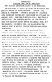
- Fig.3 shows an enlarged view of a portion of a cylindrical braid, according to the present invention, for a flexible tube of an endoscope.
- the cylindrical braid 8 is made of metallic wires 13 and heat-resistant, chemicals-resistant non-metallic monofilaments, multi-filaments or fibres 14 which are ,interwoven to form the braid 8.
- the filaments or fibres are hereinafter referred to collectively as "fibres 14".
- a plurality of metallic wires 13 and a plurality of heat-resistant, chemicals-resistant non-metallic filaments or fibres 14 are combined to form a wires and fibres group 15.
- the group 15 is formed by two to ten strands, and in the embodiment shown in F ig.3, the group 15 is formed by three metallic wires 13 and two non-metallic fibres 14. A plurality of such wires and fibres group 15 is braided diagonally to form the cylindrical braid 8.
- Twist resistant material e.g. stainless steel wires and brass wires are suitable as the metallic wires 13 of which the cylindrical braid 8 is formed.
- a suitable material must be chosen such that the fibres 14 do not disturb the soldering operation when the end pieces 10 and 11 are soldered, and such that the fibres 14 adhere strongly to the sheath 9.
- the melting temperature of the plastics material which form the sheath e.g., polyurethane resin, polyester resin or polyvinyl chloride resin, is generally about 150° to 230°C.
- the non-metallic fibres 14 must be formed by material which will withstand a -temperature of at least 150°C.
- the braid 8 and the core 7 are brazed or soldered to the end pieces 10 and 11 by relatively low melting point soldering metal, i.e. one with a melting point of about 150°C or more, so that the fibres 14 must withstand the soldering temperature and also chemical action of soldering flux, i.e. acid or alkali.
- relatively low melting point soldering metal i.e. one with a melting point of about 150°C or more
- Such heat-resistant and chemicals-resistant non-metallic materials which withstand melting temperatures of the plastics sheath and soldering metal and withstand acid and alkali and which can be formed into desired fibres 14, are organic and inorganic materials, such as polyimide, carbon, silicon carbide, boron nitride and glass. More than one material can be combined. In such materials, considering the affinity with the-sheath 9 or adhesives and mechanical strength, a preferable material is polyimide.
- a plurality of metallic wires 13 forms a metallic wires group 16
- a plurality of non-metallic fibres 14 forms a non-metallic fibres group 17.
- a plurality of wires groups 16 and fibres groups 17 is prepared and the groups are braided diagonally by a suitable braiding machine to form the interwoven cylindrical braid 8.
- the mixture ratio of the metallic wires 13 and the heat-resistant, chemically stable non-metallic fibres 14 may be varied corresponding to outside diameter of the flexible tube.
- the sheath is heated after the sheath 9 is placed over the braid 8 to melt a portion l'thereof into the interstices of the braid 8, or suitable adhesive is applied to the braid 8, and the sheath 9 is then placed over the braid 8.
- Plastics material may be applied to the braid 8 in a molten state and form the sheath after curing. In this case, affinity between the non-metallic fibres 14 and the sheath material forms a strong bond.
Abstract
Description
- . The present invention relates to an endoscope.
- An endoscope is generally formed of a forward end portion having an objective lens, a control body having an eyepiece, a bendable portion and flexible tube connected between the forward end portion and the control body. The insert portion, i.e., the forward end portion, the bendable portion and the flexible tube are inserted in the cavity of a human body, and the bendable portion is bent and operated by the control body to perform desired observations and/or operations.
- The flexible tube has as an innermost layer a tubular core formed by a helically wound metallic strip to prevent collapsing of the tube. A cylindrical braid envelopes the core to prevent the flexible tube from twisting, and a sheath formed by, e.g., a plastic tube, covers the braid. The sheath is heated to melt a portion thereof into the interstices of the cylindrical braid to secure the sheath to the braid. Alternatively, a suitable adhesive can be inserted between the sheath and the braid to secure them to each other. On both ends of the core and the braid, ring-like end pieces are integrally mounted by brazing. A conventional cylindrical braid for the flexible tube of such an endoscope is formed by a network of metallic wires. When a sheath of plastics material is adhered to the braid by heating or adhesive, sufficient bonding strength between the metal and the plastics material is not easily obtained. If separation should occur between the sheath and the braid, buckling of the flexible tube ensues, leading to failure of the endoscope.
- US-A-3,691,001 discloses that, to improve the bonding strength between a sheath and a braid which is fitted snugly about an optical fibre bundle, the braid may be formed by interwoven metallic fibres and non-metallic fibres of natural and/or synthetic fibres, e.g., silk, cotton or polyamide.
- However, as end pieces are brazed to both ends of a flexible tube, for an endoscope, if a braid made by interwoven metallic and non-metallic fibres were to be brazed to the end pieces, the non-metallic fibres forming a portion of the braid would tend to melt or oxidize and so interfere with the brazing between the end pieces and the braid. Consequently, the brazing operation would become difficult, a predetermined tensile strength of the flexible tube would not easily be obtained, and further, some of the described non-metallic fibres cannot withstand acid or alkali which forms a component of the usual brazing flux.
- ―An object of the present invention is to overcome the above-mentioned disadvantage and to provide a flexible tube for an endoscope having strong bonding strength between the sheath and the cylindrical braid and also having strong securing strength between the braid and the end pieces.
- According to the present invention, a flexible -tube for an endoscope having a tubular core made from helically wound metallic strip, a cylindrical braid member fitted over the core, a metallic annular end piece secured to each end of the core and the braid member and a plastics sheath secured to the outer surface of the braid member is characterised in that the braid is made of metallic wires and heat-resistant, chemicals-resistant non-metallic filaments and/or fibres.
- Thus, the sheath is secured very strongly to the non-metallic fibres of the braid, and the end pieces can be soldered to the metallic wires of the braid without affecting the non-metallic filaments or fibres by heat and soldering flux.
- The invention is further described, by way of example, with reference to the accompanying drawings, in which:- .
- Figure 1 is a schematic side view of an endoscope,
- Figure 2 is a partially broken enlarged side view of a portion of the flexible tube of the endoscope shown in Fig.l, and
- Figures 3 and 4 are enlarged diagrammatic views of a portion of cylindrical braid of the flexible tube respectively and showing two embodiments of the present invention.
- At first, a conventional endoscope is explained referring to Figs. 1 and 2. As shown in Fig.l, an endoscope 1 has a
forward end portion 2, abendable portion 3, aflexible tube 4 and acontrol body 5 which has an eyepiece 6 and an operating knob 61 for controlling bending of thebendable portion 3. Theforward end portion 2, thebendable portion 3 and theflexible tube 4 enclose a light guide (not shown) formed of an optical fibre bundle, for transmitting illuminating light to illuminate a desired region of a human body cavity, an image guide (not shown), formed -―of an optical fibre bundle for transmitting an image of the illuminated region, air and water feeders, and a forceps passage. The forward end of the forward end portion has outlet and inlet means for the light guide, the image guide, air and water outlets and a forceps outlet. - The
flexible tube 4 is shown in Fig.2 and has atubular core 7 which is formed by a helically wound metallic strip as an innermost layer to prevent theflexible tube 4 from collapsing. Covering thecore 7 is acylindrical braid 8 made of braided fibres to prevent theflexible tube 4 from twisting. On the whole outside surface of thebraid 8, asheath 9 made of plastics tube covers thebraid 8. Thesheath 9 is heated to melt a portion thereof into the interstices of thebraid 8 to secure the sheath to the braid. Alternatively, suitable adhesive may be applied to the surface of thebraid 8 and thesheath 9 is adhered to thebraid 8. Before thebraid 8 is covered by thesheath 9, a ring-like end piece 10 is integrally secured by brazing to one end of thecore 7 and to thebraid 8 and serves to connect the flexible tube to thebendable portion 3. Also arear end piece 11 is secured by brazing to the other end of thecore 7 and thebraid 8 to connect the flexible tube to thecontrol body 5. The brazing is performed by low melting point soldering metal. Two slenderflexible sheaths 12 pass through the flexible tube and are secured to thefront end piece 10 by soldering, the sheaths being each formed by a spirally wound strip. An operating wire (not shown) extends from the operating knob 61 of thecontrol body 5 and through eachslender sheath 12 to bend thebendable portion 3. - In the above described flexible tube, the
cylindrical braid 8 is conventionally made of metallic -wires e.g. stainless steel and brass which are braided together. In this case, when theouter sheath 9 which is made of plastics material is heated and secured to thebraid 8 by melting a portion of plastics sheath into the mesh of the braid, the bonding strength between the sheath and the braid is relatively low and the bonding tends to separate. - To improve the bonding strength between a braid and an overlying sheath, the above-mentioned US-A-3,691,001 utilizes a braid which is made of interwoven metallic wires and non-metallic fibres, e.g. silk or cotton. In this case, the
sheath 9 is bonded sufficiently strongly to the interwoven non-metallic fibres, by heating the sheath to melt a portion of the sheath into the interstices of the braid or by applying adhesive between the sheath and the braid. However, if-themetallic end pieces braid 8, even at a relatively low temperature, the non-metallic fibres which constitute a portion of thebraid 8 would tend to melt or oxidize under the applied heat and/or soldering flux. Consequently, the soldering operation would be disturbed. Further, as the non-metallic fibres would degenerate at both end portions of the braid, the bonding to the sheath would also deteriorate. Also, as the non-metallic fibres form a portion of the strength elements of the braid to resist tensile force, the tensile strength of the flexible tube would be decreased. - Fig.3 shows an enlarged view of a portion of a cylindrical braid, according to the present invention, for a flexible tube of an endoscope. In Fig.3, the
cylindrical braid 8 is made ofmetallic wires 13 and heat-resistant, chemicals-resistant non-metallic monofilaments, multi-filaments orfibres 14 which are ,interwoven to form thebraid 8. The filaments or fibres are hereinafter referred to collectively as "fibres 14". In this embodiment, a plurality ofmetallic wires 13 and a plurality of heat-resistant, chemicals-resistant non-metallic filaments orfibres 14 are combined to form a wires andfibres group 15. Normally thegroup 15 is formed by two to ten strands, and in the embodiment shown in Fig.3, thegroup 15 is formed by threemetallic wires 13 and twonon-metallic fibres 14. A plurality of such wires andfibres group 15 is braided diagonally to form thecylindrical braid 8. - To braid such
cylindrical braid 8 from the wires andfibres groups 15, each of which is formed bymetallic wires 13 andnon-metallic fibres 14, a plurality of bobbins each wound of the wires andfibres group 15 are prepared and the wires andfibres groups 15 are braided into thecylindrical braid 8 by suitable braiding machine. - Twist resistant material, e.g. stainless steel wires and brass wires are suitable as the
metallic wires 13 of which thecylindrical braid 8 is formed. - For the heat-resistant, chemicals-resistant
non-metallic fibres 14 to combine with themetallic wires 13, a suitable material must be chosen such that thefibres 14 do not disturb the soldering operation when theend pieces fibres 14 adhere strongly to thesheath 9. When thesheath 9 is heated to melt a portion of the sheath into the interstices of thebraid 8, the melting temperature of the plastics material which form thesheath 9, e.g., polyurethane resin, polyester resin or polyvinyl chloride resin, is generally about 150° to 230°C. Thus, thenon-metallic fibres 14 must be formed by material which will withstand a -temperature of at least 150°C. Also, thebraid 8 and thecore 7 are brazed or soldered to theend pieces fibres 14 must withstand the soldering temperature and also chemical action of soldering flux, i.e. acid or alkali. - Such heat-resistant and chemicals-resistant non-metallic materials which withstand melting temperatures of the plastics sheath and soldering metal and withstand acid and alkali and which can be formed into desired
fibres 14, are organic and inorganic materials, such as polyimide, carbon, silicon carbide, boron nitride and glass.. More than one material can be combined. In such materials, considering the affinity with the-sheath 9 or adhesives and mechanical strength, a preferable material is polyimide. - In the embodiment shown in Fig.4, a plurality of
metallic wires 13 forms ametallic wires group 16, and a plurality ofnon-metallic fibres 14 forms anon-metallic fibres group 17. Generally, fewer than tenwires 13 orfibres 14 for a respective group, and, in the embodiment shown in Fig.4, fivewires 13 or fivefibres 14 form each group. A plurality ofwires groups 16 andfibres groups 17 is prepared and the groups are braided diagonally by a suitable braiding machine to form the interwovencylindrical braid 8. - The mixture ratio of the
metallic wires 13 and the heat-resistant, chemically stablenon-metallic fibres 14 may be varied corresponding to outside diameter of the flexible tube. - To secure the sheath about the
cylindrical braid 8, conventionally, the sheath is heated after thesheath 9 is placed over thebraid 8 to melt a portion l'thereof into the interstices of thebraid 8, or suitable adhesive is applied to thebraid 8, and thesheath 9 is then placed over thebraid 8. Plastics material may be applied to thebraid 8 in a molten state and form the sheath after curing. In this case, affinity between thenon-metallic fibres 14 and the sheath material forms a strong bond.
Claims (7)
Priority Applications (1)
| Application Number | Priority Date | Filing Date | Title |
|---|---|---|---|
| AT83303614T ATE23013T1 (en) | 1982-06-24 | 1983-06-23 | FLEXIBLE TUBE FOR AN ENDOSCOPE. |
Applications Claiming Priority (2)
| Application Number | Priority Date | Filing Date | Title |
|---|---|---|---|
| JP107601/82 | 1982-06-24 | ||
| JP57107601A JPS5936A (en) | 1982-06-24 | 1982-06-24 | Flexible tube of endoscope |
Publications (3)
| Publication Number | Publication Date |
|---|---|
| EP0098100A2 true EP0098100A2 (en) | 1984-01-11 |
| EP0098100A3 EP0098100A3 (en) | 1984-05-09 |
| EP0098100B1 EP0098100B1 (en) | 1986-10-22 |
Family
ID=14463299
Family Applications (1)
| Application Number | Title | Priority Date | Filing Date |
|---|---|---|---|
| EP83303614A Expired EP0098100B1 (en) | 1982-06-24 | 1983-06-23 | Flexible tube for an endoscope |
Country Status (4)
| Country | Link |
|---|---|
| EP (1) | EP0098100B1 (en) |
| JP (1) | JPS5936A (en) |
| AT (1) | ATE23013T1 (en) |
| DE (1) | DE3367068D1 (en) |
Cited By (59)
| Publication number | Priority date | Publication date | Assignee | Title |
|---|---|---|---|---|
| DE3817915A1 (en) * | 1988-05-26 | 1989-11-30 | Storz Karl Gmbh & Co | FLEXIBLE ENDOSCOPE |
| EP0359549A1 (en) * | 1988-09-13 | 1990-03-21 | Vance Products Incorporated Trading As Cook Urological Incorporated | Flexible cable construction |
| EP0361314A2 (en) * | 1988-09-28 | 1990-04-04 | Advanced Cardiovascular Systems Inc | Guiding catheter with controllable distal tip |
| EP0548872A1 (en) * | 1991-12-23 | 1993-06-30 | Advanced Cardiovascular Systems, Inc. | Ultrasonic flow sensing assembly |
| EP0552429A1 (en) * | 1992-01-18 | 1993-07-28 | Richard Wolf GmbH | Endoscope with a steerable distal end portion |
| EP0715863A2 (en) | 1994-11-10 | 1996-06-12 | Target Therapeutics, Inc. | Catheter |
| US5702373A (en) * | 1995-08-31 | 1997-12-30 | Target Therapeutics, Inc. | Composite super-elastic alloy braid reinforced catheter |
| US5891114A (en) * | 1997-09-30 | 1999-04-06 | Target Therapeutics, Inc. | Soft-tip high performance braided catheter |
| US5891112A (en) * | 1995-04-28 | 1999-04-06 | Target Therapeutics, Inc. | High performance superelastic alloy braid reinforced catheter |
| WO1999044489A1 (en) * | 1998-03-06 | 1999-09-10 | Forschungszentrum Karlsruhe Gmbh | Pivotable part at the distal end of an instrument for endoscopic use |
| US5951539A (en) * | 1997-06-10 | 1999-09-14 | Target Therpeutics, Inc. | Optimized high performance multiple coil spiral-wound vascular catheter |
| US5971975A (en) * | 1996-10-09 | 1999-10-26 | Target Therapeutics, Inc. | Guide catheter with enhanced guidewire tracking |
| US6143013A (en) * | 1995-04-28 | 2000-11-07 | Target Therapeutics, Inc. | High performance braided catheter |
| US6152912A (en) * | 1997-06-10 | 2000-11-28 | Target Therapeutics, Inc. | Optimized high performance spiral-wound vascular catheter |
| US6159187A (en) * | 1996-12-06 | 2000-12-12 | Target Therapeutics, Inc. | Reinforced catheter with a formable distal tip |
| US6217566B1 (en) | 1997-10-02 | 2001-04-17 | Target Therapeutics, Inc. | Peripheral vascular delivery catheter |
| US6530913B1 (en) | 1997-04-04 | 2003-03-11 | Jeffrey Giba | Steerable catheter |
| US6638243B2 (en) | 1995-10-06 | 2003-10-28 | Target Therapeutics, Inc. | Balloon catheter with delivery side holes |
| US6689120B1 (en) | 1999-08-06 | 2004-02-10 | Boston Scientific Scimed, Inc. | Reduced profile delivery system |
| US7815599B2 (en) | 2004-12-10 | 2010-10-19 | Boston Scientific Scimed, Inc. | Catheter having an ultra soft tip and methods for making the same |
| EP3028621A1 (en) * | 2013-07-31 | 2016-06-08 | Olympus Corporation | Guide tube for endoscope and endoscope |
| US10076415B1 (en) | 2018-01-09 | 2018-09-18 | Edwards Lifesciences Corporation | Native valve repair devices and procedures |
| US10105222B1 (en) | 2018-01-09 | 2018-10-23 | Edwards Lifesciences Corporation | Native valve repair devices and procedures |
| US10111751B1 (en) | 2018-01-09 | 2018-10-30 | Edwards Lifesciences Corporation | Native valve repair devices and procedures |
| US10123873B1 (en) | 2018-01-09 | 2018-11-13 | Edwards Lifesciences Corporation | Native valve repair devices and procedures |
| US10130475B1 (en) | 2018-01-09 | 2018-11-20 | Edwards Lifesciences Corporation | Native valve repair devices and procedures |
| US10136993B1 (en) | 2018-01-09 | 2018-11-27 | Edwards Lifesciences Corporation | Native valve repair devices and procedures |
| US10159570B1 (en) | 2018-01-09 | 2018-12-25 | Edwards Lifesciences Corporation | Native valve repair devices and procedures |
| US10231837B1 (en) | 2018-01-09 | 2019-03-19 | Edwards Lifesciences Corporation | Native valve repair devices and procedures |
| US10238493B1 (en) | 2018-01-09 | 2019-03-26 | Edwards Lifesciences Corporation | Native valve repair devices and procedures |
| US10245144B1 (en) | 2018-01-09 | 2019-04-02 | Edwards Lifesciences Corporation | Native valve repair devices and procedures |
| US10507109B2 (en) | 2018-01-09 | 2019-12-17 | Edwards Lifesciences Corporation | Native valve repair devices and procedures |
| US10507108B2 (en) | 2017-04-18 | 2019-12-17 | Edwards Lifesciences Corporation | Heart valve sealing devices and delivery devices therefor |
| US10517726B2 (en) | 2015-05-14 | 2019-12-31 | Edwards Lifesciences Corporation | Heart valve sealing devices and delivery devices therefor |
| US10524792B2 (en) | 2014-12-04 | 2020-01-07 | Edwards Lifesciences Corporation | Percutaneous clip for repairing a heart valve |
| US10646342B1 (en) | 2017-05-10 | 2020-05-12 | Edwards Lifesciences Corporation | Mitral valve spacer device |
| US10653862B2 (en) | 2016-11-07 | 2020-05-19 | Edwards Lifesciences Corporation | Apparatus for the introduction and manipulation of multiple telescoping catheters |
| US10667912B2 (en) | 2017-04-18 | 2020-06-02 | Edwards Lifesciences Corporation | Heart valve sealing devices and delivery devices therefor |
| US10799312B2 (en) | 2017-04-28 | 2020-10-13 | Edwards Lifesciences Corporation | Medical device stabilizing apparatus and method of use |
| US10799677B2 (en) | 2016-03-21 | 2020-10-13 | Edwards Lifesciences Corporation | Multi-direction steerable handles for steering catheters |
| US10799675B2 (en) | 2016-03-21 | 2020-10-13 | Edwards Lifesciences Corporation | Cam controlled multi-direction steerable handles |
| US10799676B2 (en) | 2016-03-21 | 2020-10-13 | Edwards Lifesciences Corporation | Multi-direction steerable handles for steering catheters |
| US10806575B2 (en) | 2008-08-22 | 2020-10-20 | Edwards Lifesciences Corporation | Heart valve treatment system |
| US10821264B1 (en) | 2019-12-10 | 2020-11-03 | Inneuroco, Inc. | Mixed coil catheter and process for making same |
| US10835714B2 (en) | 2016-03-21 | 2020-11-17 | Edwards Lifesciences Corporation | Multi-direction steerable handles for steering catheters |
| US10905554B2 (en) | 2017-01-05 | 2021-02-02 | Edwards Lifesciences Corporation | Heart valve coaptation device |
| US10945844B2 (en) | 2018-10-10 | 2021-03-16 | Edwards Lifesciences Corporation | Heart valve sealing devices and delivery devices therefor |
| US10973638B2 (en) | 2016-07-07 | 2021-04-13 | Edwards Lifesciences Corporation | Device and method for treating vascular insufficiency |
| US10973639B2 (en) | 2018-01-09 | 2021-04-13 | Edwards Lifesciences Corporation | Native valve repair devices and procedures |
| US11040174B2 (en) | 2017-09-19 | 2021-06-22 | Edwards Lifesciences Corporation | Multi-direction steerable handles for steering catheters |
| US11051940B2 (en) | 2017-09-07 | 2021-07-06 | Edwards Lifesciences Corporation | Prosthetic spacer device for heart valve |
| US11065117B2 (en) | 2017-09-08 | 2021-07-20 | Edwards Lifesciences Corporation | Axisymmetric adjustable device for treating mitral regurgitation |
| US11207181B2 (en) | 2018-04-18 | 2021-12-28 | Edwards Lifesciences Corporation | Heart valve sealing devices and delivery devices therefor |
| US11219746B2 (en) | 2016-03-21 | 2022-01-11 | Edwards Lifesciences Corporation | Multi-direction steerable handles for steering catheters |
| US11389297B2 (en) | 2018-04-12 | 2022-07-19 | Edwards Lifesciences Corporation | Mitral valve spacer device |
| US11547564B2 (en) | 2018-01-09 | 2023-01-10 | Edwards Lifesciences Corporation | Native valve repair devices and procedures |
| US11583396B2 (en) | 2009-12-04 | 2023-02-21 | Edwards Lifesciences Corporation | Prosthetic valve for replacing mitral valve |
| US11839544B2 (en) | 2019-02-14 | 2023-12-12 | Edwards Lifesciences Corporation | Heart valve sealing devices and delivery devices therefor |
| US11969346B2 (en) | 2021-01-29 | 2024-04-30 | Edwards Lifesciences Corporation | Heart valve coaptation device |
Families Citing this family (9)
| Publication number | Priority date | Publication date | Assignee | Title |
|---|---|---|---|---|
| JPH0783740B2 (en) * | 1985-12-05 | 1995-09-13 | 旭光学工業株式会社 | Flexible tube for endoscope |
| JPS63169102U (en) * | 1987-04-24 | 1988-11-02 | ||
| JPH0724086Y2 (en) * | 1989-05-01 | 1995-06-05 | 株式会社町田製作所 | Channel tube for endoscope |
| US5002041A (en) * | 1989-05-12 | 1991-03-26 | Kabushiki Kaisha Machida Seisakusho | Bending device and flexible tube structure |
| US6648854B1 (en) | 1999-05-14 | 2003-11-18 | Scimed Life Systems, Inc. | Single lumen balloon-tipped micro catheter with reinforced shaft |
| US20040199052A1 (en) | 2003-04-01 | 2004-10-07 | Scimed Life Systems, Inc. | Endoscopic imaging system |
| JP5048555B2 (en) * | 2008-03-12 | 2012-10-17 | 富士フイルム株式会社 | Method for manufacturing flexible tube for endoscope |
| JP5580538B2 (en) * | 2009-01-26 | 2014-08-27 | 富士フイルム株式会社 | Endoscope device |
| CN105310640A (en) * | 2015-11-30 | 2016-02-10 | 浙江异札特机械科技有限公司 | Gastroscope cannula of improved structure |
Citations (6)
| Publication number | Priority date | Publication date | Assignee | Title |
|---|---|---|---|---|
| US3498286A (en) * | 1966-09-21 | 1970-03-03 | American Optical Corp | Catheters |
| DE2006406A1 (en) * | 1969-02-12 | 1970-08-27 | Olympus Optical Co., Ltd., Tokio | Flexible plastics endoscope tube reinforced - by metal strips |
| US3691001A (en) * | 1968-11-14 | 1972-09-12 | Olympus Optical Co | Flexible protecting sheath of an elongated flexible optical fiber bundle |
| FR2282080A1 (en) * | 1974-08-14 | 1976-03-12 | Tuyaux Flexibles & Forge | Tape profile yarns for woven reinforcement for rubber hose - to reduce the number of yarns necessary for an impermeable structure |
| FR2285564A1 (en) * | 1974-09-23 | 1976-04-16 | Cfea | High pressure flexible tubing - allows greater flexibility and cheaper and quicker prodn. than current types |
| US3998216A (en) * | 1973-10-04 | 1976-12-21 | Olympus Optical Co., Ltd. | Bending tube for endoscope |
Family Cites Families (2)
| Publication number | Priority date | Publication date | Assignee | Title |
|---|---|---|---|---|
| JPS4831673U (en) * | 1971-08-20 | 1973-04-17 | ||
| JPS5630786U (en) * | 1979-08-18 | 1981-03-25 |
-
1982
- 1982-06-24 JP JP57107601A patent/JPS5936A/en active Pending
-
1983
- 1983-06-23 AT AT83303614T patent/ATE23013T1/en not_active IP Right Cessation
- 1983-06-23 EP EP83303614A patent/EP0098100B1/en not_active Expired
- 1983-06-23 DE DE8383303614T patent/DE3367068D1/en not_active Expired
Patent Citations (6)
| Publication number | Priority date | Publication date | Assignee | Title |
|---|---|---|---|---|
| US3498286A (en) * | 1966-09-21 | 1970-03-03 | American Optical Corp | Catheters |
| US3691001A (en) * | 1968-11-14 | 1972-09-12 | Olympus Optical Co | Flexible protecting sheath of an elongated flexible optical fiber bundle |
| DE2006406A1 (en) * | 1969-02-12 | 1970-08-27 | Olympus Optical Co., Ltd., Tokio | Flexible plastics endoscope tube reinforced - by metal strips |
| US3998216A (en) * | 1973-10-04 | 1976-12-21 | Olympus Optical Co., Ltd. | Bending tube for endoscope |
| FR2282080A1 (en) * | 1974-08-14 | 1976-03-12 | Tuyaux Flexibles & Forge | Tape profile yarns for woven reinforcement for rubber hose - to reduce the number of yarns necessary for an impermeable structure |
| FR2285564A1 (en) * | 1974-09-23 | 1976-04-16 | Cfea | High pressure flexible tubing - allows greater flexibility and cheaper and quicker prodn. than current types |
Cited By (146)
| Publication number | Priority date | Publication date | Assignee | Title |
|---|---|---|---|---|
| DE3817915A1 (en) * | 1988-05-26 | 1989-11-30 | Storz Karl Gmbh & Co | FLEXIBLE ENDOSCOPE |
| WO1989011242A1 (en) * | 1988-05-26 | 1989-11-30 | Karl Storz Gmbh & Co. | Flexible endoscope |
| EP0359549A1 (en) * | 1988-09-13 | 1990-03-21 | Vance Products Incorporated Trading As Cook Urological Incorporated | Flexible cable construction |
| AU621660B2 (en) * | 1988-09-13 | 1992-03-19 | Vance Products Incorporated | Flexible cable construction |
| EP0361314A2 (en) * | 1988-09-28 | 1990-04-04 | Advanced Cardiovascular Systems Inc | Guiding catheter with controllable distal tip |
| EP0361314A3 (en) * | 1988-09-28 | 1990-09-12 | Advanced Cardiovascular System | Guiding catheter with controllable distal tip |
| EP0548872A1 (en) * | 1991-12-23 | 1993-06-30 | Advanced Cardiovascular Systems, Inc. | Ultrasonic flow sensing assembly |
| EP0552429A1 (en) * | 1992-01-18 | 1993-07-28 | Richard Wolf GmbH | Endoscope with a steerable distal end portion |
| US5299562A (en) * | 1992-01-18 | 1994-04-05 | Richard Wolf Gmbh | Endoscope having a controllable distal end piece |
| US5658264A (en) * | 1994-11-10 | 1997-08-19 | Target Therapeutics, Inc. | High performance spiral-wound catheter |
| US5795341A (en) * | 1994-11-10 | 1998-08-18 | Target Therapeutics, Inc. | High performance spiral-wound catheter |
| US5853400A (en) * | 1994-11-10 | 1998-12-29 | Target Therapeutics, Inc. | High performance spiral-wound catheter |
| EP0715863A2 (en) | 1994-11-10 | 1996-06-12 | Target Therapeutics, Inc. | Catheter |
| US5891112A (en) * | 1995-04-28 | 1999-04-06 | Target Therapeutics, Inc. | High performance superelastic alloy braid reinforced catheter |
| US6143013A (en) * | 1995-04-28 | 2000-11-07 | Target Therapeutics, Inc. | High performance braided catheter |
| US5702373A (en) * | 1995-08-31 | 1997-12-30 | Target Therapeutics, Inc. | Composite super-elastic alloy braid reinforced catheter |
| US6638243B2 (en) | 1995-10-06 | 2003-10-28 | Target Therapeutics, Inc. | Balloon catheter with delivery side holes |
| US5971975A (en) * | 1996-10-09 | 1999-10-26 | Target Therapeutics, Inc. | Guide catheter with enhanced guidewire tracking |
| US6159187A (en) * | 1996-12-06 | 2000-12-12 | Target Therapeutics, Inc. | Reinforced catheter with a formable distal tip |
| US6530913B1 (en) | 1997-04-04 | 2003-03-11 | Jeffrey Giba | Steerable catheter |
| US6152912A (en) * | 1997-06-10 | 2000-11-28 | Target Therapeutics, Inc. | Optimized high performance spiral-wound vascular catheter |
| US5951539A (en) * | 1997-06-10 | 1999-09-14 | Target Therpeutics, Inc. | Optimized high performance multiple coil spiral-wound vascular catheter |
| US5891114A (en) * | 1997-09-30 | 1999-04-06 | Target Therapeutics, Inc. | Soft-tip high performance braided catheter |
| US6165163A (en) * | 1997-09-30 | 2000-12-26 | Target Therapeutics, Inc. | Soft-tip performance braided catheter |
| US6217566B1 (en) | 1997-10-02 | 2001-04-17 | Target Therapeutics, Inc. | Peripheral vascular delivery catheter |
| WO1999044489A1 (en) * | 1998-03-06 | 1999-09-10 | Forschungszentrum Karlsruhe Gmbh | Pivotable part at the distal end of an instrument for endoscopic use |
| US6689120B1 (en) | 1999-08-06 | 2004-02-10 | Boston Scientific Scimed, Inc. | Reduced profile delivery system |
| US7815599B2 (en) | 2004-12-10 | 2010-10-19 | Boston Scientific Scimed, Inc. | Catheter having an ultra soft tip and methods for making the same |
| US11116632B2 (en) | 2008-08-22 | 2021-09-14 | Edwards Lifesciences Corporation | Transvascular delivery systems |
| US11540918B2 (en) | 2008-08-22 | 2023-01-03 | Edwards Lifesciences Corporation | Prosthetic heart valve and delivery apparatus |
| US11116631B2 (en) | 2008-08-22 | 2021-09-14 | Edwards Lifesciences Corporation | Prosthetic heart valve delivery methods |
| US11957582B2 (en) | 2008-08-22 | 2024-04-16 | Edwards Lifesciences Corporation | Prosthetic heart valve and delivery apparatus |
| US11141270B2 (en) | 2008-08-22 | 2021-10-12 | Edwards Lifesciences Corporation | Prosthetic heart valve and delivery apparatus |
| US10945839B2 (en) | 2008-08-22 | 2021-03-16 | Edwards Lifesciences Corporation | Prosthetic heart valve and delivery apparatus |
| US10932906B2 (en) | 2008-08-22 | 2021-03-02 | Edwards Lifesciences Corporation | Prosthetic heart valve and delivery apparatus |
| US11109970B2 (en) | 2008-08-22 | 2021-09-07 | Edwards Lifesciences Corporation | Prosthetic heart valve and delivery apparatus |
| US11730597B2 (en) | 2008-08-22 | 2023-08-22 | Edwards Lifesciences Corporation | Prosthetic heart valve and delivery apparatus |
| US10820994B2 (en) | 2008-08-22 | 2020-11-03 | Edwards Lifesciences Corporation | Methods for delivering a prosthetic valve |
| US11690718B2 (en) | 2008-08-22 | 2023-07-04 | Edwards Lifesciences Corporation | Prosthetic heart valve and delivery apparatus |
| US10806575B2 (en) | 2008-08-22 | 2020-10-20 | Edwards Lifesciences Corporation | Heart valve treatment system |
| US11583396B2 (en) | 2009-12-04 | 2023-02-21 | Edwards Lifesciences Corporation | Prosthetic valve for replacing mitral valve |
| US11660185B2 (en) | 2009-12-04 | 2023-05-30 | Edwards Lifesciences Corporation | Ventricular anchors for valve repair and replacement devices |
| US11911264B2 (en) | 2009-12-04 | 2024-02-27 | Edwards Lifesciences Corporation | Valve repair and replacement devices |
| US10016118B2 (en) | 2013-07-31 | 2018-07-10 | Olympus Corporation | Endoscope guide tube and endoscope |
| EP3028621A4 (en) * | 2013-07-31 | 2017-03-29 | Olympus Corporation | Guide tube for endoscope and endoscope |
| EP3028621A1 (en) * | 2013-07-31 | 2016-06-08 | Olympus Corporation | Guide tube for endoscope and endoscope |
| US10524792B2 (en) | 2014-12-04 | 2020-01-07 | Edwards Lifesciences Corporation | Percutaneous clip for repairing a heart valve |
| US11690621B2 (en) | 2014-12-04 | 2023-07-04 | Edwards Lifesciences Corporation | Percutaneous clip for repairing a heart valve |
| US11793642B2 (en) | 2015-05-14 | 2023-10-24 | Edwards Lifesciences Corporation | Heart valve sealing devices and delivery devices therefor |
| US10517726B2 (en) | 2015-05-14 | 2019-12-31 | Edwards Lifesciences Corporation | Heart valve sealing devices and delivery devices therefor |
| US10799675B2 (en) | 2016-03-21 | 2020-10-13 | Edwards Lifesciences Corporation | Cam controlled multi-direction steerable handles |
| US10799677B2 (en) | 2016-03-21 | 2020-10-13 | Edwards Lifesciences Corporation | Multi-direction steerable handles for steering catheters |
| US10799676B2 (en) | 2016-03-21 | 2020-10-13 | Edwards Lifesciences Corporation | Multi-direction steerable handles for steering catheters |
| US11951263B2 (en) | 2016-03-21 | 2024-04-09 | Edwards Lifesciences Corporation | Multi-direction steerable handles |
| US11219746B2 (en) | 2016-03-21 | 2022-01-11 | Edwards Lifesciences Corporation | Multi-direction steerable handles for steering catheters |
| US10835714B2 (en) | 2016-03-21 | 2020-11-17 | Edwards Lifesciences Corporation | Multi-direction steerable handles for steering catheters |
| US10973638B2 (en) | 2016-07-07 | 2021-04-13 | Edwards Lifesciences Corporation | Device and method for treating vascular insufficiency |
| US11517718B2 (en) | 2016-11-07 | 2022-12-06 | Edwards Lifesciences Corporation | Apparatus for the introduction and manipulation of multiple telescoping catheters |
| US10653862B2 (en) | 2016-11-07 | 2020-05-19 | Edwards Lifesciences Corporation | Apparatus for the introduction and manipulation of multiple telescoping catheters |
| US10905554B2 (en) | 2017-01-05 | 2021-02-02 | Edwards Lifesciences Corporation | Heart valve coaptation device |
| US10898327B2 (en) | 2017-04-18 | 2021-01-26 | Edwards Lifesciences Corporation | Heart valve sealing devices and delivery devices therefor |
| US10932908B2 (en) | 2017-04-18 | 2021-03-02 | Edwards Lifesciences Corporation | Heart valve sealing devices and delivery devices therefor |
| US10869763B2 (en) | 2017-04-18 | 2020-12-22 | Edwards Lifesciences Corporation | Heart valve sealing devices and delivery devices therefor |
| US10874514B2 (en) | 2017-04-18 | 2020-12-29 | Edwards Lifesciences Corporation | Heart valve sealing devices and delivery devices therefor |
| US10888425B2 (en) | 2017-04-18 | 2021-01-12 | Edwards Lifesciences Corporation | Heart valve sealing devices and delivery devices therefor |
| US11602431B2 (en) | 2017-04-18 | 2023-03-14 | Edwards Lifesciences Corporation | Heart valve sealing devices and delivery devices therefor |
| US10905553B2 (en) | 2017-04-18 | 2021-02-02 | Edwards Lifesciences Corporation | Heart valve sealing devices and delivery devices therefor |
| US10905552B2 (en) | 2017-04-18 | 2021-02-02 | Edwards Lifesciences Corporation | Heart valve sealing devices and delivery devices therefor |
| US10842627B2 (en) | 2017-04-18 | 2020-11-24 | Edwards Lifesciences Corporation | Heart valve sealing devices and delivery devices therefor |
| US10918482B2 (en) | 2017-04-18 | 2021-02-16 | Edwards Lifesciences Corporation | Heart valve sealing devices and delivery devices therefor |
| US11179240B2 (en) | 2017-04-18 | 2021-11-23 | Edwards Lifesciences Corporation | Heart valve sealing devices and delivery devices therefor |
| US10925734B2 (en) | 2017-04-18 | 2021-02-23 | Edwards Lifesciences Corporation | Heart valve sealing devices and delivery devices therefor |
| US10925733B2 (en) | 2017-04-18 | 2021-02-23 | Edwards Lifesciences Corporation | Heart valve sealing devices and delivery devices therefor |
| US11723772B2 (en) | 2017-04-18 | 2023-08-15 | Edwards Lifesciences Corporation | Heart valve sealing devices and delivery devices therefor |
| US10925732B2 (en) | 2017-04-18 | 2021-02-23 | Edwards Lifesciences Corporation | Heart valve sealing devices and delivery devices therefor |
| US10849754B2 (en) | 2017-04-18 | 2020-12-01 | Edwards Lifesciences Corporation | Heart valve sealing devices and delivery devices therefor |
| US11850153B2 (en) | 2017-04-18 | 2023-12-26 | Edwards Lifesciences Corporation | Heart valve sealing devices and delivery devices therefor |
| US10940005B2 (en) | 2017-04-18 | 2021-03-09 | Edwards Lifesciences Corporation | Heart valve sealing devices and delivery devices therefor |
| US11224511B2 (en) | 2017-04-18 | 2022-01-18 | Edwards Lifesciences Corporation | Heart valve sealing devices and delivery devices therefor |
| US11160657B2 (en) | 2017-04-18 | 2021-11-02 | Edwards Lifesciences Corporation | Heart valve sealing devices and delivery devices therefor |
| US10945843B2 (en) | 2017-04-18 | 2021-03-16 | Edwards Lifesciences Corporation | Heart valve sealing devices and delivery devices therefor |
| US10952853B2 (en) | 2017-04-18 | 2021-03-23 | Edwards Lifesciences Corporation | Heart valve sealing devices and delivery devices therefor |
| US11234822B2 (en) | 2017-04-18 | 2022-02-01 | Edwards Lifesciences Corporation | Heart valve sealing devices and delivery devices therefor |
| US10667912B2 (en) | 2017-04-18 | 2020-06-02 | Edwards Lifesciences Corporation | Heart valve sealing devices and delivery devices therefor |
| US10959848B2 (en) | 2017-04-18 | 2021-03-30 | Edwards Lifesciences Corporation | Heart valve sealing devices and delivery devices therefor |
| US11013601B2 (en) | 2017-04-18 | 2021-05-25 | Edwards Lifesciences Corporation | Heart valve sealing devices and delivery devices therefor |
| US10524913B2 (en) | 2017-04-18 | 2020-01-07 | Edwards Lifesciences Corporation | Heart valve sealing devices and delivery devices therefor |
| US10507108B2 (en) | 2017-04-18 | 2019-12-17 | Edwards Lifesciences Corporation | Heart valve sealing devices and delivery devices therefor |
| US11096784B2 (en) | 2017-04-18 | 2021-08-24 | Edwards Lifesciences Corporation | Heart valve sealing devices and delivery devices therefor |
| US11058539B2 (en) | 2017-04-18 | 2021-07-13 | Edwards Lifesciences Corporation | Heart valve sealing devices and delivery devices therefor |
| US11000373B2 (en) | 2017-04-18 | 2021-05-11 | Edwards Lifesciences Corporation | Heart valve sealing devices and delivery devices therefor |
| US11020229B2 (en) | 2017-04-18 | 2021-06-01 | Edwards Lifesciences Corporation | Heart valve sealing devices and delivery devices therefor |
| US11166778B2 (en) | 2017-04-28 | 2021-11-09 | Edwards Lifesciences Corporation | Medical device stabilizing apparatus and method of use |
| US10799312B2 (en) | 2017-04-28 | 2020-10-13 | Edwards Lifesciences Corporation | Medical device stabilizing apparatus and method of use |
| US11406468B2 (en) | 2017-04-28 | 2022-08-09 | Edwards Lifesciences Corporation | Medical device stabilizing apparatus and method of use |
| US10959846B2 (en) | 2017-05-10 | 2021-03-30 | Edwards Lifesciences Corporation | Mitral valve spacer device |
| US10646342B1 (en) | 2017-05-10 | 2020-05-12 | Edwards Lifesciences Corporation | Mitral valve spacer device |
| US10820998B2 (en) | 2017-05-10 | 2020-11-03 | Edwards Lifesciences Corporation | Valve repair device |
| US11051940B2 (en) | 2017-09-07 | 2021-07-06 | Edwards Lifesciences Corporation | Prosthetic spacer device for heart valve |
| US11730598B2 (en) | 2017-09-07 | 2023-08-22 | Edwards Lifesciences Corporation | Prosthetic device for heart valve |
| US11065117B2 (en) | 2017-09-08 | 2021-07-20 | Edwards Lifesciences Corporation | Axisymmetric adjustable device for treating mitral regurgitation |
| US11040174B2 (en) | 2017-09-19 | 2021-06-22 | Edwards Lifesciences Corporation | Multi-direction steerable handles for steering catheters |
| US11944762B2 (en) | 2017-09-19 | 2024-04-02 | Edwards Lifesciences Corporation | Multi-direction steerable handles for steering catheters |
| US11110251B2 (en) | 2017-09-19 | 2021-09-07 | Edwards Lifesciences Corporation | Multi-direction steerable handles for steering catheters |
| US11850154B2 (en) | 2018-01-09 | 2023-12-26 | Edwards Lifesciences Corporation | Native valve repair devices and procedures |
| US11259927B2 (en) | 2018-01-09 | 2022-03-01 | Edwards Lifesciences Corporation | Native valve repair devices and procedures |
| US10959847B2 (en) | 2018-01-09 | 2021-03-30 | Edwards Lifesciences Corporation | Native valve repair devices and procedures |
| US10111751B1 (en) | 2018-01-09 | 2018-10-30 | Edwards Lifesciences Corporation | Native valve repair devices and procedures |
| US10123873B1 (en) | 2018-01-09 | 2018-11-13 | Edwards Lifesciences Corporation | Native valve repair devices and procedures |
| US10925735B2 (en) | 2018-01-09 | 2021-02-23 | Edwards Lifesciences Corporation | Native valve repair devices and procedures |
| US10918483B2 (en) | 2018-01-09 | 2021-02-16 | Edwards Lifesciences Corporation | Native valve repair devices and procedures |
| US10231837B1 (en) | 2018-01-09 | 2019-03-19 | Edwards Lifesciences Corporation | Native valve repair devices and procedures |
| US10238493B1 (en) | 2018-01-09 | 2019-03-26 | Edwards Lifesciences Corporation | Native valve repair devices and procedures |
| US10973639B2 (en) | 2018-01-09 | 2021-04-13 | Edwards Lifesciences Corporation | Native valve repair devices and procedures |
| US10130475B1 (en) | 2018-01-09 | 2018-11-20 | Edwards Lifesciences Corporation | Native valve repair devices and procedures |
| US10813760B2 (en) | 2018-01-09 | 2020-10-27 | Edwards Lifesciences Corporation | Native valve repair devices and procedures |
| US10136993B1 (en) | 2018-01-09 | 2018-11-27 | Edwards Lifesciences Corporation | Native valve repair devices and procedures |
| US11013598B2 (en) | 2018-01-09 | 2021-05-25 | Edwards Lifesciences Corporation | Native valve repair devices and procedures |
| US11918469B2 (en) | 2018-01-09 | 2024-03-05 | Edwards Lifesciences Corporation | Native valve repair devices and procedures |
| US11298228B2 (en) | 2018-01-09 | 2022-04-12 | Edwards Lifesciences Corporation | Native valve repair devices and procedures |
| US10159570B1 (en) | 2018-01-09 | 2018-12-25 | Edwards Lifesciences Corporation | Native valve repair devices and procedures |
| US10245144B1 (en) | 2018-01-09 | 2019-04-02 | Edwards Lifesciences Corporation | Native valve repair devices and procedures |
| US10105222B1 (en) | 2018-01-09 | 2018-10-23 | Edwards Lifesciences Corporation | Native valve repair devices and procedures |
| US10076415B1 (en) | 2018-01-09 | 2018-09-18 | Edwards Lifesciences Corporation | Native valve repair devices and procedures |
| US11039925B2 (en) | 2018-01-09 | 2021-06-22 | Edwards Lifesciences Corporation | Native valve repair devices and procedures |
| US11547564B2 (en) | 2018-01-09 | 2023-01-10 | Edwards Lifesciences Corporation | Native valve repair devices and procedures |
| US10595997B2 (en) | 2018-01-09 | 2020-03-24 | Edwards Lifesciences Corporation | Native valve repair devices and procedures |
| US10507109B2 (en) | 2018-01-09 | 2019-12-17 | Edwards Lifesciences Corporation | Native valve repair devices and procedures |
| US11612485B2 (en) | 2018-01-09 | 2023-03-28 | Edwards Lifesciences Corporation | Native valve repair devices and procedures |
| US11389297B2 (en) | 2018-04-12 | 2022-07-19 | Edwards Lifesciences Corporation | Mitral valve spacer device |
| US11207181B2 (en) | 2018-04-18 | 2021-12-28 | Edwards Lifesciences Corporation | Heart valve sealing devices and delivery devices therefor |
| US11129717B2 (en) | 2018-10-10 | 2021-09-28 | Edwards Lifesciences Corporation | Heart valve sealing devices and delivery devices therefor |
| US11202710B2 (en) | 2018-10-10 | 2021-12-21 | Edwards Lifesciences Corporation | Heart valve sealing devices and delivery devices therefor |
| US11278409B2 (en) | 2018-10-10 | 2022-03-22 | Edwards Lifesciences Corporation | Heart valve sealing devices and delivery devices therefor |
| US11234823B2 (en) | 2018-10-10 | 2022-02-01 | Edwards Lifesciences Corporation | Heart valve sealing devices and delivery devices therefor |
| US11766330B2 (en) | 2018-10-10 | 2023-09-26 | Edwards Lifesciences Corporation | Valve repair devices for repairing a native valve of a patient |
| US11000375B2 (en) | 2018-10-10 | 2021-05-11 | Edwards Lifesciences Corporation | Heart valve sealing devices and delivery devices therefor |
| US11083582B2 (en) | 2018-10-10 | 2021-08-10 | Edwards Lifesciences Corporation | Heart valve sealing devices and delivery devices therefor |
| US11344415B2 (en) | 2018-10-10 | 2022-05-31 | Edwards Lifesciences Corporation | Heart valve sealing devices and delivery devices therefor |
| US10945844B2 (en) | 2018-10-10 | 2021-03-16 | Edwards Lifesciences Corporation | Heart valve sealing devices and delivery devices therefor |
| US11147672B2 (en) | 2018-10-10 | 2021-10-19 | Edwards Lifesciences Corporation | Heart valve sealing devices and delivery devices therefor |
| US10987221B2 (en) | 2018-10-10 | 2021-04-27 | Edwards Lifesciences Corporation | Heart valve sealing devices and delivery devices therefor |
| US10993809B2 (en) | 2018-10-10 | 2021-05-04 | Edwards Lifesciences Corporation | Heart valve sealing devices and delivery devices therefor |
| US11839544B2 (en) | 2019-02-14 | 2023-12-12 | Edwards Lifesciences Corporation | Heart valve sealing devices and delivery devices therefor |
| US10821264B1 (en) | 2019-12-10 | 2020-11-03 | Inneuroco, Inc. | Mixed coil catheter and process for making same |
| US11969346B2 (en) | 2021-01-29 | 2024-04-30 | Edwards Lifesciences Corporation | Heart valve coaptation device |
Also Published As
| Publication number | Publication date |
|---|---|
| EP0098100A3 (en) | 1984-05-09 |
| DE3367068D1 (en) | 1986-11-27 |
| ATE23013T1 (en) | 1986-11-15 |
| EP0098100B1 (en) | 1986-10-22 |
| JPS5936A (en) | 1984-01-05 |
Similar Documents
| Publication | Publication Date | Title |
|---|---|---|
| EP0098100B1 (en) | Flexible tube for an endoscope | |
| US6458075B1 (en) | Endoscopic flexible tube | |
| EP0535847B1 (en) | Endoscope | |
| US3691001A (en) | Flexible protecting sheath of an elongated flexible optical fiber bundle | |
| US4708434A (en) | Fiberscope with bending mechanism | |
| JP3283195B2 (en) | Endoscope flexible tube | |
| US6937801B2 (en) | High density fiber optic cable | |
| JP2006507055A (en) | Kink preventing access sheath and method for manufacturing the same | |
| EP0430542A2 (en) | Method of producing flexible tube | |
| JPH0951870A (en) | Flexible tube for endoscope | |
| CN115298767A (en) | Wiring member | |
| EP0005029A1 (en) | Optical fibre cables | |
| JP4017734B2 (en) | Endoscope insertion part | |
| JP2001070238A (en) | Flexible tube of endoscope | |
| JP2556002Y2 (en) | Endoscope | |
| JP3969856B2 (en) | Endoscope | |
| JP3515710B2 (en) | Endoscope flexible tube | |
| JP3670765B2 (en) | Endoscope flexible tube | |
| JP3542782B2 (en) | Pipe Guide Manufacturing Method | |
| US5812719A (en) | Sheath for a flexible fiber optic lightguide, and the lightguide | |
| JPS6146923A (en) | Flexible tube for endoscope | |
| JPS63305836A (en) | Endoscope | |
| JP4708589B2 (en) | Endoscope flexible tube | |
| JP2002209834A (en) | Flexible pipe of endoscope and method for manufacturing the same | |
| JPH0951871A (en) | Flexible tube for endoscope |
Legal Events
| Date | Code | Title | Description |
|---|---|---|---|
| PUAI | Public reference made under article 153(3) epc to a published international application that has entered the european phase |
Free format text: ORIGINAL CODE: 0009012 |
|
| AK | Designated contracting states |
Designated state(s): AT BE CH DE FR GB IT LI LU NL SE |
|
| PUAL | Search report despatched |
Free format text: ORIGINAL CODE: 0009013 |
|
| AK | Designated contracting states |
Designated state(s): AT BE CH DE FR GB IT LI LU NL SE |
|
| 17P | Request for examination filed |
Effective date: 19840413 |
|
| GRAA | (expected) grant |
Free format text: ORIGINAL CODE: 0009210 |
|
| AK | Designated contracting states |
Kind code of ref document: B1 Designated state(s): AT BE CH DE FR GB IT LI LU NL SE |
|
| PG25 | Lapsed in a contracting state [announced via postgrant information from national office to epo] |
Ref country code: NL Effective date: 19861022 Ref country code: LI Effective date: 19861022 Ref country code: IT Free format text: LAPSE BECAUSE OF FAILURE TO SUBMIT A TRANSLATION OF THE DESCRIPTION OR TO PAY THE FEE WITHIN THE PRESCRIBED TIME-LIMIT;WARNING: LAPSES OF ITALIAN PATENTS WITH EFFECTIVE DATE BEFORE 2007 MAY HAVE OCCURRED AT ANY TIME BEFORE 2007. THE CORRECT EFFECTIVE DATE MAY BE DIFFERENT FROM THE ONE RECORDED. Effective date: 19861022 Ref country code: CH Effective date: 19861022 Ref country code: BE Effective date: 19861022 Ref country code: AT Effective date: 19861022 |
|
| REF | Corresponds to: |
Ref document number: 23013 Country of ref document: AT Date of ref document: 19861115 Kind code of ref document: T |
|
| PG25 | Lapsed in a contracting state [announced via postgrant information from national office to epo] |
Ref country code: SE Effective date: 19861031 |
|
| REF | Corresponds to: |
Ref document number: 3367068 Country of ref document: DE Date of ref document: 19861127 |
|
| REG | Reference to a national code |
Ref country code: CH Ref legal event code: PL |
|
| ET | Fr: translation filed | ||
| NLV1 | Nl: lapsed or annulled due to failure to fulfill the requirements of art. 29p and 29m of the patents act | ||
| PG25 | Lapsed in a contracting state [announced via postgrant information from national office to epo] |
Ref country code: LU Free format text: LAPSE BECAUSE OF NON-PAYMENT OF DUE FEES Effective date: 19870630 |
|
| PLBE | No opposition filed within time limit |
Free format text: ORIGINAL CODE: 0009261 |
|
| STAA | Information on the status of an ep patent application or granted ep patent |
Free format text: STATUS: NO OPPOSITION FILED WITHIN TIME LIMIT |
|
| 26N | No opposition filed | ||
| PGFP | Annual fee paid to national office [announced via postgrant information from national office to epo] |
Ref country code: FR Payment date: 19940609 Year of fee payment: 12 |
|
| PGFP | Annual fee paid to national office [announced via postgrant information from national office to epo] |
Ref country code: GB Payment date: 19940615 Year of fee payment: 12 |
|
| PGFP | Annual fee paid to national office [announced via postgrant information from national office to epo] |
Ref country code: DE Payment date: 19940622 Year of fee payment: 12 |
|
| PG25 | Lapsed in a contracting state [announced via postgrant information from national office to epo] |
Ref country code: GB Effective date: 19950623 |
|
| GBPC | Gb: european patent ceased through non-payment of renewal fee |
Effective date: 19950623 |
|
| PG25 | Lapsed in a contracting state [announced via postgrant information from national office to epo] |
Ref country code: FR Effective date: 19960229 |
|
| PG25 | Lapsed in a contracting state [announced via postgrant information from national office to epo] |
Ref country code: DE Effective date: 19960301 |
|
| REG | Reference to a national code |
Ref country code: FR Ref legal event code: ST |