EP0098169A2 - Data processing system - Google Patents
Data processing system Download PDFInfo
- Publication number
- EP0098169A2 EP0098169A2 EP83303786A EP83303786A EP0098169A2 EP 0098169 A2 EP0098169 A2 EP 0098169A2 EP 83303786 A EP83303786 A EP 83303786A EP 83303786 A EP83303786 A EP 83303786A EP 0098169 A2 EP0098169 A2 EP 0098169A2
- Authority
- EP
- European Patent Office
- Prior art keywords
- measurement
- processing
- performance measurement
- instruction
- information
- Prior art date
- Legal status (The legal status is an assumption and is not a legal conclusion. Google has not performed a legal analysis and makes no representation as to the accuracy of the status listed.)
- Granted
Links
Images


Classifications
-
- G—PHYSICS
- G06—COMPUTING; CALCULATING OR COUNTING
- G06F—ELECTRIC DIGITAL DATA PROCESSING
- G06F11/00—Error detection; Error correction; Monitoring
- G06F11/22—Detection or location of defective computer hardware by testing during standby operation or during idle time, e.g. start-up testing
- G06F11/24—Marginal checking or other specified testing methods not covered by G06F11/26, e.g. race tests
-
- G—PHYSICS
- G06—COMPUTING; CALCULATING OR COUNTING
- G06F—ELECTRIC DIGITAL DATA PROCESSING
- G06F11/00—Error detection; Error correction; Monitoring
- G06F11/30—Monitoring
- G06F11/34—Recording or statistical evaluation of computer activity, e.g. of down time, of input/output operation ; Recording or statistical evaluation of user activity, e.g. usability assessment
- G06F11/3466—Performance evaluation by tracing or monitoring
- G06F11/348—Circuit details, i.e. tracer hardware
-
- G—PHYSICS
- G06—COMPUTING; CALCULATING OR COUNTING
- G06F—ELECTRIC DIGITAL DATA PROCESSING
- G06F9/00—Arrangements for program control, e.g. control units
- G06F9/06—Arrangements for program control, e.g. control units using stored programs, i.e. using an internal store of processing equipment to receive or retain programs
- G06F9/46—Multiprogramming arrangements
Definitions
- This invention relates to a data processing system comprising performance measurement system and more specifically the invention provides a data processing system capable of ' measuring performance using a timer provided therein.
- Performance measurement of a data processing system which executes instructions on the main storage by fetching them gives an important guideline to development of a system for the next phase, for example and design of softwares.
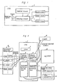
- Fig. 1 is an example of existing system.
- An existing performance measurement of a data processing system is configurated, for example, by the logic circuits of hardware as shown in Fig. 1.
- a processing system 1 is provided, for example, with the counter circuits 4-1 4-n for each performance measurement item such as instruction appearing frequency measurement etc. and a selection circuit 3 selects a signal of the point for performance measurement through the control of control circuit 2 and thereby each counter circuit 4-1 : 4-n are operated by the trigger signals determined for respective measuring items.
- a large amount of hardware only for performance measurement are necessary, the performance measurement items are fixed and performance of other items than that stored in the computer system precedingly cannot be measured.
- performance measurement is carried out by the softwares operating under usual operating system, it is requested to consider that execution of a program itself for performance measurement realized by the software does not give any adverse effect on the result of measurement.
- control is transferred to the performance measurement system utilizing external interruption of timer by a setting value of timer within the processing system for triggering performance measurement, and results of processings for each measurement item obtained by such performance measurement are collected, for example, on the main storage.
- a data processing system of.this invention is 'characterized by providing;
- Fig. 1 is a system by prior art as described above.
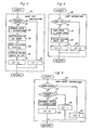
- Fig. 2 is the structure of an embodiment of this invention.
- Fig. 3 is an example of log area of this invention.
- Fig. 4 is an example of measurement control table.
- Fig. 5 through Fig. 9 are profiles of processings of the performance measurement setting part.
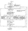
- Fig. 10 through Fig. 11 are profiles of processings of the performance measurement processing part.
- Fig. 12 is a structure of hardware of data processing system of the preferred embodiment.
- 1 is a processing system
- 5 is a performance measurement instructing part
- 6-1 ⁇ 6-4 are performance measurement setting instructions and paticularly 6-1 is a mode set instruction
- 6-2 is a start instruction
- 6-3 is a stop instruction
- 6-4 is a mode reset instruction.
- 7 is a program state word (PSW)
- 8 is a program interruption processing part
- 9 is a performance measurement setting part
- 10 is an external interruption processing part
- 11 is a performance measurement processing part
- 12 is a timer
- 13 is a log area
- 14 is a measurement control table
- 15 is a state control information setting area
- 16 is an item information setting area.
- the processing system 1 executes instructions on the main storage by fetching them and performs data processings.
- the performance measurement instructing part 5 is composed of machine words instruction groups indicating performance measurement of processing system 1, and particularly operates the firmware to be described later by issuing the performance measurement setting instructions 6-1 to 6-4 provided in this invention.
- the performance measurement setting instructions for example, the mode set instruction 6-1 for setting the performance measurement items by selecting them, start instruction 6-2 for instructing start of performance measurement, stop instruction 6-3 for instructing end of performance measurement, and mode reset instruction 6-4 releasing setting of selected performance measurement items.
- the machine word instruction consists of the instruction code indicating kind of instruction and operand indicating an object of operation, but undefined instruction code is assigned to above performance measurement setting instructions 6-1 ⁇ 6-4. Therefore, when these instructions 6-1 ⁇ 6-4 are executed by the processing system 1, a program interrupt is generated by operation exception due to detection of invalid instruction.
- the program interrupt processing part 8 executes processings corresponding to various program interruption through the processings that when program interrupt is generated by various exceptional conditions detected by execution of instructions, control is transferred through the save of content of PSW 7 and update of it. If program interrupt occurs by execution of performance measurement setting instructions 6-1 ⁇ 6-4, the performance measurement setting part 9 structured by the firmware is started.
- the performance measurement setting part 9 sets the control information designated by the mode set instruction 6-1 to the measurement control table 14 and controls start of measurement by setting the timer 12 in the timing of the start instruction 6-2. Details processings are described later.
- the timer 12 operates in the same way as the ordinary CPU timer and when the present time has passed, an external interrupt is generated.
- a timer can newly be provided for performance measurement but an existing timer such as dispatch timer, for example, used for dispatch of virtual computer system may also be used. In this embodiment, a dispatch timer is used.
- an external interrupt processing part 10 When an external interrupt is generated, an external interrupt processing part 10 is started.
- the external interrupt processing part 10 starts the performance measurement processing part 11 by the interrupt code when such interrupt is caused by the timer 12.
- the performance measurement processing part 11 is structured by firmware and as described later, collects the performance measurement information and stores it to the log area 13.
- An external interrupt due to the timer 12 is generated with a period designated freely by the mode set instruction 6-1-and therefore the performance measurement processing part 11 randomly performs sampling of measurement data with an external interrupt considered as a trigger.
- the log area 13 for the instruction appearing frequency measurement is for example constructed as shown in Fig. 3 and is reserved within the main storage.
- the area of 4 bytes is reserved in each instruction code for each of the supervisor (SUP) mode of the processing system 1 and a problem program (PP) mode, and a relative address in the log area 13 is determined, as shown in the figure, by the state mode obtained from the 15th bit of PSW7 and the instruction code of 16th bit containing the instruction sub-code. Therefore, the performance measurement processing part 11 is capable of counting up the directly checked instruction appearing frequency.
- the measurement control table 14 is for example configurated as shown in Fig. 4.
- the state flag 15-1 which is set to "1" by the mode set instruction 6-1 or to "0” by the mode reset instruction 6-4 and the state flag 15-2 which is set to "1” by the start instruction 6-2 or to "0” by the stop instruction 6-3.
- the sampling interval control bit 15-3 is also provided.
- the sampling period of 3.3 ms or 422.4ms can be selected by OFF/ON of said bit 15-3, it is naturally possible to freely select more sampling periods by increasing a number of instructing bits.
- the item information setting domain 16 for example, the item ID indicating the measurement items and the address indicating the collecting range thereof are set for each item.
- FLAG16-1 indicates whether the logical address indicating the collecting reange is valid or invalid.
- the program interrupt processing part 8 When, a program interrupt is generated, the program interrupt processing part 8 is started and the program interrupt processing part 8 judges first, by the processing 20 sh,own in Fig. 5, whether the program interrupt code is the operation exception (X'Ol') or not. When it is not operation exception, ordnary program interrupt processing is executed. In case it is opertion exception, an instruction code which has caused program interrupt is fetched by the processing 21 and then analyzed. As a result of analysis, when the performance measurement setting instruction 6-1 to 6-4 is judged, the performance measurement setting part 9 is started.
- the performance measurement setting part 9 calls, with the instruction code, the mode set instruction processing part 22, start instruction processing part 23, stop instruction processing part 24 and mode reset instruction processing part 25, executes the processing of instructions 6-1 to 6-4 as described later, Then processing returns to the interrupt generating area after the condition code (CC) indicating result of execution is set.
- CC condition code
- the mode set instruction processing part 22 executes processings as shown in Fig. 6. First, according to the processing 30 shown in Fig. 6, it is checked, by referring to the state flag 15-1 of the measurement control table 14 shown in Fig. 4, whether current state is ENABLE or DISABLE. If current state is ENABLE, CC is set to "1" by the processing 36 and the processing returns to the calling area. If the state is DISABLE, the state flag 15-1 is turned ON by the processing 31 and thereby the state becomes ENABLE. Then, the log area 13 is initialized by the processing 32 and the item information is set to the measurement control table 14 on the basis of the information designated by the operand of mode set instruction 6-1 by the processing 33. Moreover, the sampling interval control bit 15-3 is set to "0" or “1” by the processing 34 and finally CC is set to "0" indicating the normal end by the processing 35 and then processing returns to the calling area.
- the start instruction processing part 23 executes processing as shown in Fig. 7. First, the state flags 15-2 and 15-1 of the measurement control table 14 are checked by the processings 40 and 41 shown in Fig. 7.. If the START state is already started, CC is set to "1" by the processing 49, and when the current state is DISABLE, CC is set to "2" by the processing 48, and the processing returns to the called area. If the current state is STOP state and ENABLE state, control is transferred to the processing 42, the state flag 15-2 is turned ON and thereby the START state appears.
- the dispatch timer 12 is set to 422.4 ms by the processing 44, or such bit is OFF, the dispatch timer 12 is set to 3.3 ms by the processing 45. Moreover, external interrupt mask of timer 12 is turned ON by the processing 46 and thereby inhibit of external interrupt is cancelled. Thereby, an external interrupt is generated after time passage of 3.3 ms or 422.4 ms.
- CC is set to "0" by the processing 47 and the processing returns to the calling area.
- the STOP instruction processing part 24 executes processing as shown in Fig. 8. First, the START state has started or not is judged by the processing 50. If current state is START, CC is set to "2" by the processing 54 and the processing returns. When the current state is START, it is changed to the STOP state by the processing 51, and external interrupt mask due to the timer 12 is turned ON by the processing 52, thereby inhibitting interruption. Thereby, sampling is i suspended. Then CC is set to "0" by the processing 53 and thereafter the processing returns to the calling area.
- the mode reset instruction processing part 25 executes the processings as indicated in Fig. 9. It is first checked whether current state is START or not by the processing 60. When the START state has started, CC is set to "2" by the processing 65, and the processing returns to the calling area. Then, it is checked by the processing 61 whether current state is DISABLE or not. When current state is DISABLE, CC is set to "1". by the processing 64. When it is ENABLE, it is changed to DISABLE and CC is set to "0" by the processing 63. Then, processing returns to the calling area.
- the external interrupt processing part 10 When an external interrupt is generated, the external interrupt processing part 10 is started. The external interrupt processing part 10 judges whether the external interrupt code is X'1008' or not, namely it is an interrupt by the dispatch timer 12 or not by the processing 70 shown in Fig. 10. If not, existing ordinary interrupt processing is carried out. If an interrupt by timer 12 is generated, control is transferred to the performance measurement processing part 11.
- the performance measurement processing part 11 turns ON the internal flag by the processing 71.
- This internal flag is a control flag for sequential processing in such a case that the external interrupt is generated in double.
- an address of log area 13 is fetched by the processing 72 and the measurement item is decoded based on the measurement control table 14.
- various measurement processing part such as the instruction appearing frequency measurement processing part 73, PSW instruction code trace processing part 74, executable instruction logic address distribution measurement processing part 75 in the problem program mode, executable instruction logic address distribution processing part 76 etc. are called.
- measurement information about processing system 1 at the interrupt timing is collected in the specified area of the log area.
- a value of 3.3 ms or 422.4 ms is set to the dispatch timer 12 by the processing 77.
- the processing returns to the interrupt generating point.
- the instruction appearing frequency processing part 73 executes processings, for example, as shown in Fig. 11.
- First, the old PSW of external interrupt to which the PSW 7 at the time when external interrupt is generated is fetched by the processing 80 shown in Fig. 11.
- the instruction code and instruction sub-code at the time when an interrupt is generated is fetched on the basis of the instruction address of the old PSW by the processing 83.
- the relative address in the log area 13 is generated by the processing 84 and appearing frequency of the corresponding instruction is updated by the processing 85.
- the PSW instruction code trace processing part 74 performs the execution to directly trace contents or instruction code of PSW when an interrupt is generated to the log area 13.
- the executable instruction logic address distribution measurement processing parts 75 and 76 execute the processing for counting the appearing frequency of executable instruction for each presegmented logical address range. In the same way, the instruction can be called by providing the processing part which collects desired measurement information.
- 100 is a central processing unit (CPU), 101 is a main storage (MS), 102 is a firmware domain, 103 is an operating system ( O S)domain, 104 is an instruction register, 105 is an OP code part, 106 is a control storage (CS), 107 - 110 are micro operation words corresponding to MODE SET instruction 6-1, START instruction 6-2, STOP instruction 6-3 and MODE RESET instruction 6-4 shown in Fig. 2.
- CPU central processing unit
- MS main storage
- 102 is a firmware domain
- 103 is an operating system ( O S)domain
- 104 is an instruction register
- 105 is an OP code part
- 106 is a control storage (CS)
- 107 - 110 are micro operation words corresponding to MODE SET instruction 6-1, START instruction 6-2, STOP instruction 6-3 and MODE RESET instruction 6-4 shown in Fig. 2.
- 111 is an invalid instructing flag
- 112 is a CS data register
- 113 is a timer circuit
- 114 is a timer interrupt flag
- 115 is an interrupt control circuit
- 116 is a system control latch
- 117 is a system base register
- 118 is an address register
- 119 is an interrupt signal line instructing ordinary interrupt to the OS domain
- 120 is an interrupt signal line instructing interrupt to the firmware domain
- 121 is a control gate.
- the MODE SET instruction 6-1, START instruction 6-2, STOP instruction 6-3, MODE RESET instruction 6-4 are read and they are set to the instruction register 104. Then, the corresponding micro operation words 107 - 110 in the CS106 are also read by the OP code 105 of it. Since above instructions are invalid instructions, the invalid instructing flag 111 in the micro operation word is turned ON("1") and this invalid instructing flag is held by the CS data register 112. When the invalid instructing flag becomes ON, the interrupt control circuit 115 is started through the interrupt signal line 120 and simultaneously, the system control latch 116 is set.
- the interrupt control circuit 115 sets the specified address in the OS area 103 to the address register 118 but when the system control latch 16 is ON, contents of system base register 117 is coupled to the upper part of the address register 118 through the control gate 121. For this reason, when the system control latch 116 is in the set state, start to the OS area 103 is not triggered but start to the firmware domain 102 is triggered. Thereby, the instruction groups within the firmware domain are sequentially read and the performance measurement setting processing is carried out.
- the timer interrupt flag 114 becomes ON and the interrupt control circuit 115 is started through the interrupt signal line 120.
- the operation similar to that carried out when the invalid instructing flag is ON is also carried out and start to the firmware domain 102 is triggered.
- the performance measurement processing etc. is carried out by the instruction groups within the firmware domain.
- this invention is capable of setting desired performance measurement items without using an exclusive hardware for fixing the performance measurement items.
- various functions of existing processing system can directly be used. Therefore, this invention can be introduced rather easily into the existing processing system.
- the log area in the desired size can also be provided, : ensuring exellent flexibility and expandability.
- desired measurement information can be obtained any time desired by properly adjusting the overhead for the ordinary processing by the performance measurement.
Abstract
Description
- This invention relates to a data processing system comprising performance measurement system and more specifically the invention provides a data processing system capable of ' measuring performance using a timer provided therein.
- Performance measurement of a data processing system which executes instructions on the main storage by fetching them gives an important guideline to development of a system for the next phase, for example and design of softwares.
- Fig. 1 is an example of existing system. An existing performance measurement of a data processing system is configurated, for example, by the logic circuits of hardware as shown in Fig. 1. A
processing system 1 is provided, for example, with the counter circuits 4-1 4-n for each performance measurement item such as instruction appearing frequency measurement etc. and a selection circuit 3 selects a signal of the point for performance measurement through the control ofcontrol circuit 2 and thereby each counter circuit 4-1 : 4-n are operated by the trigger signals determined for respective measuring items. According to such system of the prior art, a large amount of hardware only for performance measurement are necessary, the performance measurement items are fixed and performance of other items than that stored in the computer system precedingly cannot be measured. However, if performance measurement is carried out by the softwares operating under usual operating system, it is requested to consider that execution of a program itself for performance measurement realized by the software does not give any adverse effect on the result of measurement. - It is an object of this invention to provide a performance measurement system which has eliminated above problems and has flexibility so that desired performance measurement items can be set without using hardwares fixing the performance measurement items.
- Therefore, in this invention, in order to attain this object, control is transferred to the performance measurement system utilizing external interruption of timer by a setting value of timer within the processing system for triggering performance measurement, and results of processings for each measurement item obtained by such performance measurement are collected, for example, on the main storage.
- Namely, a data processing system of.this invention is 'characterized by providing;
- a measurement information storing means to which measurement information is stored corresponding to the performance measurement items,
- a measurement control information storing means to which the performance measurement item information and performance measurement condition information are stored,
- a timer,
- a measurement control information setting processing part for controlling information setting to said measurement control information storing means, and
- a performance measurement processing part which is started by sampling instructing interruption by said timer and collects measurement information to said measurement information storing means based on said performance measurement item information and performance measurement condition information.
- Fig. 1 is a system by prior art as described above. Fig. 2 is the structure of an embodiment of this invention. Fig. 3 is an example of log area of this invention. Fig. 4 is an example of measurement control table. Fig. 5 through Fig. 9 are profiles of processings of the performance measurement setting part. Fig. 10 through Fig. 11 are profiles of processings of the performance measurement processing part. Fig. 12 is a structure of hardware of data processing system of the preferred embodiment.
- In an embodiment shown in Fig. 2, 1 is a processing system, 5 is a performance measurement instructing part, 6-1 ~6-4 are performance measurement setting instructions and paticularly 6-1 is a mode set instruction, 6-2 is a start instruction, 6-3 is a stop instruction, 6-4 is a mode reset instruction. 7 is a program state word (PSW) , 8 is a program interruption processing part, 9 is a performance measurement setting part, 10 is an external interruption processing part, 11 is a performance measurement processing part, 12 is a timer, 13 is a log area, 14 is a measurement control table, 15 is a state control information setting area, 16 is an item information setting area.
- The
processing system 1 executes instructions on the main storage by fetching them and performs data processings. The performancemeasurement instructing part 5 is composed of machine words instruction groups indicating performance measurement ofprocessing system 1, and particularly operates the firmware to be described later by issuing the performance measurement setting instructions 6-1 to 6-4 provided in this invention. As the performance measurement setting instructions, for example, the mode set instruction 6-1 for setting the performance measurement items by selecting them, start instruction 6-2 for instructing start of performance measurement, stop instruction 6-3 for instructing end of performance measurement, and mode reset instruction 6-4 releasing setting of selected performance measurement items. Generally, the machine word instruction consists of the instruction code indicating kind of instruction and operand indicating an object of operation, but undefined instruction code is assigned to above performance measurement setting instructions 6-1 ~ 6-4. Therefore, when these instructions 6-1 ~ 6-4 are executed by theprocessing system 1, a program interrupt is generated by operation exception due to detection of invalid instruction. - The program
interrupt processing part 8 executes processings corresponding to various program interruption through the processings that when program interrupt is generated by various exceptional conditions detected by execution of instructions, control is transferred through the save of content ofPSW 7 and update of it. If program interrupt occurs by execution of performance measurement setting instructions 6-1 ~ 6-4, the performance measurement setting part 9 structured by the firmware is started. - The performance measurement setting part 9 sets the control information designated by the mode set instruction 6-1 to the measurement control table 14 and controls start of measurement by setting the
timer 12 in the timing of the start instruction 6-2. Details processings are described later. Thetimer 12 operates in the same way as the ordinary CPU timer and when the present time has passed, an external interrupt is generated. A timer can newly be provided for performance measurement but an existing timer such as dispatch timer, for example, used for dispatch of virtual computer system may also be used. In this embodiment, a dispatch timer is used. - When an external interrupt is generated, an external
interrupt processing part 10 is started. The externalinterrupt processing part 10 starts the performancemeasurement processing part 11 by the interrupt code when such interrupt is caused by thetimer 12. The performancemeasurement processing part 11 is structured by firmware and as described later, collects the performance measurement information and stores it to thelog area 13. An external interrupt due to thetimer 12 is generated with a period designated freely by the mode set instruction 6-1-and therefore the performancemeasurement processing part 11 randomly performs sampling of measurement data with an external interrupt considered as a trigger. - As a performance measurement item, there is, for example, a appearing frequency measurement of each instruction. The
log area 13 for the instruction appearing frequency measurement is for example constructed as shown in Fig. 3 and is reserved within the main storage. The area of 4 bytes is reserved in each instruction code for each of the supervisor (SUP) mode of theprocessing system 1 and a problem program (PP) mode, and a relative address in thelog area 13 is determined, as shown in the figure, by the state mode obtained from the 15th bit of PSW7 and the instruction code of 16th bit containing the instruction sub-code. Therefore, the performancemeasurement processing part 11 is capable of counting up the directly checked instruction appearing frequency. - The measurement control table 14 is for example configurated as shown in Fig. 4. In the state control
information setting domain 15 of the measurement control table 14, the state flag 15-1 which is set to "1" by the mode set instruction 6-1 or to "0" by the mode reset instruction 6-4 and the state flag 15-2 which is set to "1" by the start instruction 6-2 or to "0" by the stop instruction 6-3. In addition, the sampling interval control bit 15-3 is also provided. In this embodiment, the sampling period of 3.3 ms or 422.4ms can be selected by OFF/ON of said bit 15-3, it is naturally possible to freely select more sampling periods by increasing a number of instructing bits. In the iteminformation setting domain 16, for example, the item ID indicating the measurement items and the address indicating the collecting range thereof are set for each item. FLAG16-1 indicates whether the logical address indicating the collecting reange is valid or invalid. - By referring to Fig. 5 through Fig. 9, processings of the performance measurement setting part 9 is described.
- When, a program interrupt is generated, the program
interrupt processing part 8 is started and the program interruptprocessing part 8 judges first, by theprocessing 20 sh,own in Fig. 5, whether the program interrupt code is the operation exception (X'Ol') or not. When it is not operation exception, ordnary program interrupt processing is executed. In case it is opertion exception, an instruction code which has caused program interrupt is fetched by theprocessing 21 and then analyzed. As a result of analysis, when the performance measurement setting instruction 6-1 to 6-4 is judged, the performance measurement setting part 9 is started. - The performance measurement setting part 9 calls, with the instruction code, the mode set
instruction processing part 22, startinstruction processing part 23, stopinstruction processing part 24 and mode resetinstruction processing part 25, executes the processing of instructions 6-1 to 6-4 as described later, Then processing returns to the interrupt generating area after the condition code (CC) indicating result of execution is set. - The mode set
instruction processing part 22 executes processings as shown in Fig. 6. First, according to theprocessing 30 shown in Fig. 6, it is checked, by referring to the state flag 15-1 of the measurement control table 14 shown in Fig. 4, whether current state is ENABLE or DISABLE. If current state is ENABLE, CC is set to "1" by theprocessing 36 and the processing returns to the calling area. If the state is DISABLE, the state flag 15-1 is turned ON by the processing 31 and thereby the state becomes ENABLE. Then, thelog area 13 is initialized by theprocessing 32 and the item information is set to the measurement control table 14 on the basis of the information designated by the operand of mode set instruction 6-1 by theprocessing 33. Moreover, the sampling interval control bit 15-3 is set to "0" or "1" by theprocessing 34 and finally CC is set to "0" indicating the normal end by theprocessing 35 and then processing returns to the calling area. - The start
instruction processing part 23 executes processing as shown in Fig. 7. First, the state flags 15-2 and 15-1 of the measurement control table 14 are checked by theprocessings processing 49, and when the current state is DISABLE, CC is set to "2" by theprocessing 48, and the processing returns to the called area. If the current state is STOP state and ENABLE state, control is transferred to theprocessing 42, the state flag 15-2 is turned ON and thereby the START state appears. Then, if the sampling interval control bit 15-3 is ON as a result of reference thereto, thedispatch timer 12 is set to 422.4 ms by theprocessing 44, or such bit is OFF, thedispatch timer 12 is set to 3.3 ms by theprocessing 45. Moreover, external interrupt mask oftimer 12 is turned ON by theprocessing 46 and thereby inhibit of external interrupt is cancelled. Thereby, an external interrupt is generated after time passage of 3.3 ms or 422.4 ms. When the external interrupt mask is turned ON, CC is set to "0" by theprocessing 47 and the processing returns to the calling area. - The STOP
instruction processing part 24 executes processing as shown in Fig. 8. First, the START state has started or not is judged by theprocessing 50. If current state is START, CC is set to "2" by theprocessing 54 and the processing returns. When the current state is START, it is changed to the STOP state by theprocessing 51, and external interrupt mask due to thetimer 12 is turned ON by theprocessing 52, thereby inhibitting interruption. Thereby, sampling is i suspended. Then CC is set to "0" by theprocessing 53 and thereafter the processing returns to the calling area. - The mode reset
instruction processing part 25 executes the processings as indicated in Fig. 9. It is first checked whether current state is START or not by the processing 60. When the START state has started, CC is set to "2" by theprocessing 65, and the processing returns to the calling area. Then, it is checked by theprocessing 61 whether current state is DISABLE or not. When current state is DISABLE, CC is set to "1". by theprocessing 64. When it is ENABLE, it is changed to DISABLE and CC is set to "0" by the processing 63. Then, processing returns to the calling area. - Processings of the performance
measurement processing part 11 is then described by referring to Fig. 10 and Fig. 11. - When an external interrupt is generated, the external interrupt processing
part 10 is started. The external interrupt processingpart 10 judges whether the external interrupt code is X'1008' or not, namely it is an interrupt by thedispatch timer 12 or not by theprocessing 70 shown in Fig. 10. If not, existing ordinary interrupt processing is carried out. If an interrupt bytimer 12 is generated, control is transferred to the performancemeasurement processing part 11. - The performance
measurement processing part 11 turns ON the internal flag by theprocessing 71. This internal flag is a control flag for sequential processing in such a case that the external interrupt is generated in double. Then, i an address oflog area 13 is fetched by theprocessing 72 and the measurement item is decoded based on the measurement control table 14. Thereafter, according to the result of decoding, various measurement processing part such as the instruction appearing frequencymeasurement processing part 73, PSW instruction codetrace processing part 74, executable instruction logic address distributionmeasurement processing part 75 in the problem program mode, executable instruction logic addressdistribution processing part 76 etc. are called. By these processings, measurement information aboutprocessing system 1 at the interrupt timing is collected in the specified area of the log area. For the next sampling, a value of 3.3 ms or 422.4 ms is set to thedispatch timer 12 by theprocessing 77. Then after said internal flag is turned OFF by theprocessing 78, the processing returns to the interrupt generating point. - The instruction appearing
frequency processing part 73 executes processings, for example, as shown in Fig. 11. First, the old PSW of external interrupt to which thePSW 7 at the time when external interrupt is generated is fetched by theprocessing 80 shown in Fig. 11. Then, it is checked whether the logical address is valid or not by referring to the FLAG 16-1 of the measurement control table 14 by theprocessing 81. If it is invalid, it is checked, by theprocessing 82, whether an instruction address obtained from said old PSW is within the measurement information collecting range, designated by the measurement control table 14, or not. If i it is out of the range, no information is collected. If within the range, the instruction code and instruction sub-code at the time when an interrupt is generated is fetched on the basis of the instruction address of the old PSW by theprocessing 83. As described for Fig. 3, the relative address in thelog area 13 is generated by theprocessing 84 and appearing frequency of the corresponding instruction is updated by theprocessing 85. When above processings are repeated for each external interruption generated with the preset sampling synchronization, a randomized accurate instruction appearing frequency information as a whole can be obtained. If the executing period of each instruction in theprocessing system 1 is different, it is necessary to adjust result of collect- tion by weighting them with the inverse value of executing time. - The PSW instruction code
trace processing part 74 performs the execution to directly trace contents or instruction code of PSW when an interrupt is generated to thelog area 13. The executable instruction logic address distributionmeasurement processing parts - The, hardware operation in this embodiment is described. In Fig. 12, 100 is a central processing unit (CPU), 101 is a main storage (MS), 102 is a firmware domain, 103 is an operating system (OS)domain, 104 is an instruction register, 105 is an OP code part, 106 is a control storage (CS), 107 - 110 are micro operation words corresponding to MODE SET instruction 6-1, START instruction 6-2, STOP instruction 6-3 and MODE RESET instruction 6-4 shown in Fig. 2. 111 is an invalid instructing flag, 112 is a CS data register, 113 is a timer circuit, 114 is a timer interrupt flag, 115 is an interrupt control circuit, 116 is a system control latch, 117 is a system base register, 118 is an address register, 119 is an interrupt signal line instructing ordinary interrupt to the OS domain, 120 is an interrupt signal line instructing interrupt to the firmware domain, and 121 is a control gate.
- First, during execution of the ordinary program processings, the MODE SET instruction 6-1, START instruction 6-2, STOP instruction 6-3, MODE RESET instruction 6-4 are read and they are set to the
instruction register 104. Then, the corresponding micro operation words 107 - 110 in the CS106 are also read by theOP code 105 of it. Since above instructions are invalid instructions, the invalid instructingflag 111 in the micro operation word is turned ON("1") and this invalid instructing flag is held by the CS data register 112. When the invalid instructing flag becomes ON, the interruptcontrol circuit 115 is started through the interruptsignal line 120 and simultaneously, thesystem control latch 116 is set. The interruptcontrol circuit 115 sets the specified address in theOS area 103 to theaddress register 118 but when thesystem control latch 16 is ON, contents ofsystem base register 117 is coupled to the upper part of theaddress register 118 through thecontrol gate 121. For this reason, when thesystem control latch 116 is in the set state, start to theOS area 103 is not triggered but start to thefirmware domain 102 is triggered. Thereby, the instruction groups within the firmware domain are sequentially read and the performance measurement setting processing is carried out. - When a count value set by the
timer circuit 113 is completed, the timer interruptflag 114 becomes ON and the interruptcontrol circuit 115 is started through the interruptsignal line 120. At this time, the operation similar to that carried out when the invalid instructing flag is ON is also carried out and start to thefirmware domain 102 is triggered. In the case of this timer interrupt, the performance measurement processing etc. is carried out by the instruction groups within the firmware domain. - In the case of ordinary interrupt operation to the
OS area 108, the interruptsignal line 119 becomes ON and thesystem control latch 116 is reset. Therefore, any incremental shift of address is not carried out. - As described above, this invention is capable of setting desired performance measurement items without using an exclusive hardware for fixing the performance measurement items. Particularly, various functions of existing processing system can directly be used. Therefore, this invention can be introduced rather easily into the existing processing system. The log area in the desired size can also be provided, : ensuring exellent flexibility and expandability. Moreover, since the sampling interval can also be adjusted freely, desired measurement information can be obtained any time desired by properly adjusting the overhead for the ordinary processing by the performance measurement.
Claims (4)
Applications Claiming Priority (2)
| Application Number | Priority Date | Filing Date | Title |
|---|---|---|---|
| JP113317/82 | 1982-06-30 | ||
| JP57113317A JPS593651A (en) | 1982-06-30 | 1982-06-30 | Performance measurement system by firmware |
Publications (3)
| Publication Number | Publication Date |
|---|---|
| EP0098169A2 true EP0098169A2 (en) | 1984-01-11 |
| EP0098169A3 EP0098169A3 (en) | 1985-10-09 |
| EP0098169B1 EP0098169B1 (en) | 1989-05-10 |
Family
ID=14609160
Family Applications (1)
| Application Number | Title | Priority Date | Filing Date |
|---|---|---|---|
| EP83303786A Expired EP0098169B1 (en) | 1982-06-30 | 1983-06-30 | Data processing system |
Country Status (9)
| Country | Link |
|---|---|
| US (1) | US4601008A (en) |
| EP (1) | EP0098169B1 (en) |
| JP (1) | JPS593651A (en) |
| KR (1) | KR870000115B1 (en) |
| AU (1) | AU546369B2 (en) |
| BR (1) | BR8303530A (en) |
| CA (1) | CA1198825A (en) |
| DE (1) | DE3379851D1 (en) |
| ES (1) | ES523749A0 (en) |
Cited By (11)
| Publication number | Priority date | Publication date | Assignee | Title |
|---|---|---|---|---|
| EP0259224A2 (en) * | 1986-09-02 | 1988-03-09 | Digital Equipment Corporation | Method for performance evaluation of a data processor system |
| US5062055A (en) * | 1986-09-02 | 1991-10-29 | Digital Equipment Corporation | Data processor performance advisor |
| WO2011085313A1 (en) * | 2010-01-11 | 2011-07-14 | Qualcomm Incorporated | System and method of sampling data within a central processing unit |
| WO2011084336A1 (en) * | 2009-12-16 | 2011-07-14 | Qualcomm Incorporated | System and method for controlling central processing unit power with reduced frequency oscillations |
| CN102934045A (en) * | 2009-12-16 | 2013-02-13 | 高通股份有限公司 | System and method for controlling central processing unit power with guaranteed transient deadlines |
| US8650426B2 (en) | 2009-12-16 | 2014-02-11 | Qualcomm Incorporated | System and method for controlling central processing unit power in a virtualized system |
| US8689037B2 (en) | 2009-12-16 | 2014-04-01 | Qualcomm Incorporated | System and method for asynchronously and independently controlling core clocks in a multicore central processing unit |
| US8775830B2 (en) | 2009-12-16 | 2014-07-08 | Qualcomm Incorporated | System and method for dynamically controlling a plurality of cores in a multicore central processing unit based on temperature |
| US9104411B2 (en) | 2009-12-16 | 2015-08-11 | Qualcomm Incorporated | System and method for controlling central processing unit power with guaranteed transient deadlines |
| US9176572B2 (en) | 2009-12-16 | 2015-11-03 | Qualcomm Incorporated | System and method for controlling central processing unit power with guaranteed transient deadlines |
| US9563250B2 (en) | 2009-12-16 | 2017-02-07 | Qualcomm Incorporated | System and method for controlling central processing unit power based on inferred workload parallelism |
Families Citing this family (29)
| Publication number | Priority date | Publication date | Assignee | Title |
|---|---|---|---|---|
| JPS6024647A (en) * | 1983-07-20 | 1985-02-07 | Hitachi Ltd | Autonomous resource managing system of system |
| US5047919A (en) * | 1986-04-03 | 1991-09-10 | Harris Corporation | Method and apparatus for monitoring software execution in a parallel multiprocessor computer system |
| US5283907A (en) * | 1986-05-20 | 1994-02-01 | Robert Bosch Gmbh | Process for safeguarding transfer of data from a temporary part into a main part of a non-volatile memory |
| US4910663A (en) * | 1987-07-10 | 1990-03-20 | Tandem Computers Incorporated | System for measuring program execution by replacing an executable instruction with interrupt causing instruction |
| JP2712396B2 (en) * | 1987-10-26 | 1998-02-10 | 日本電気株式会社 | Performance analysis and diagnosis system for computer systems |
| US4905171A (en) * | 1987-11-09 | 1990-02-27 | International Business Machines Corporation | Workstation controller performance monitor |
| US5003462A (en) * | 1988-05-31 | 1991-03-26 | International Business Machines Corporation | Apparatus and method for implementing precise interrupts on a pipelined processor with multiple functional units with separate address translation interrupt means |
| US5369764A (en) * | 1990-04-25 | 1994-11-29 | Blair; Gary L. | Method for sharing access to database elements in a data processing system |
| JP3213765B2 (en) * | 1991-03-11 | 2001-10-02 | サン・マイクロシステムズ・インコーポレーテッド | Method and apparatus for optimizing cost-based heuristic instruction scheduling for pipeline processors |
| US5301312A (en) * | 1991-08-21 | 1994-04-05 | International Business Machines Corporation | Method and system for utilizing benign fault occurrence to measure interrupt-blocking times |
| JP3290280B2 (en) * | 1994-01-13 | 2002-06-10 | 株式会社東芝 | Information processing device |
| WO1995025304A1 (en) * | 1994-03-14 | 1995-09-21 | Green Hills Software, Inc. | Optimizing time and testing of higher level language programs |
| JP3727382B2 (en) * | 1994-12-26 | 2005-12-14 | 三菱電機株式会社 | Control software execution system control method |
| US5881222A (en) * | 1995-01-23 | 1999-03-09 | International Business Machines Corporation | Method and apparatus for detecting performance problems in a windows-based computer system |
| US6148437A (en) * | 1998-05-04 | 2000-11-14 | Hewlett-Packard Company | System and method for jump-evaluated trace designation |
| US6467007B1 (en) * | 1999-05-19 | 2002-10-15 | International Business Machines Corporation | Processor reset generated via memory access interrupt |
| US6959291B1 (en) | 1999-05-19 | 2005-10-25 | International Business Machines Corporation | Management of a concurrent use license in a logically-partitioned computer |
| US6691146B1 (en) | 1999-05-19 | 2004-02-10 | International Business Machines Corporation | Logical partition manager and method |
| US6681240B1 (en) | 1999-05-19 | 2004-01-20 | International Business Machines Corporation | Apparatus and method for specifying maximum interactive performance in a logical partition of a computer system independently from the maximum interactive performance in other partitions |
| US7770034B2 (en) * | 2003-12-16 | 2010-08-03 | Intel Corporation | Performance monitoring based dynamic voltage and frequency scaling |
| US7200824B1 (en) * | 2004-11-16 | 2007-04-03 | Altera Corporation | Performance/power mapping of a die |
| US7346787B2 (en) * | 2004-12-07 | 2008-03-18 | Intel Corporation | System and method for adaptive power management |
| US7814485B2 (en) * | 2004-12-07 | 2010-10-12 | Intel Corporation | System and method for adaptive power management based on processor utilization and cache misses |
| JPWO2007043144A1 (en) * | 2005-10-05 | 2009-04-16 | ヒューレット−パッカード デベロップメント カンパニー エル.ピー. | Load test apparatus and method |
| JP5029245B2 (en) * | 2007-09-20 | 2012-09-19 | 富士通セミコンダクター株式会社 | Profiling method and program |
| US9766672B2 (en) | 2007-12-28 | 2017-09-19 | Intel Corporation | System for managing power provided to a processor or memory based on a measured memory consumption characteristic |
| US7971084B2 (en) | 2007-12-28 | 2011-06-28 | Intel Corporation | Power management in electronic systems |
| WO2009147738A1 (en) * | 2008-06-05 | 2009-12-10 | 富士通株式会社 | Information processor, its control method and monitor program |
| US20110145559A1 (en) * | 2009-12-16 | 2011-06-16 | Thomson Steven S | System and method for controlling central processing unit power with guaranteed steady state deadlines |
Citations (3)
| Publication number | Priority date | Publication date | Assignee | Title |
|---|---|---|---|---|
| US3771144A (en) * | 1972-07-24 | 1973-11-06 | Ibm | Clock for computer performance measurements |
| US3906454A (en) * | 1973-05-18 | 1975-09-16 | Bell Telephone Labor Inc | Computer monitoring system |
| US4231106A (en) * | 1978-07-13 | 1980-10-28 | Sperry Rand Corporation | Performance monitor apparatus and method |
Family Cites Families (3)
| Publication number | Priority date | Publication date | Assignee | Title |
|---|---|---|---|---|
| US3688263A (en) * | 1971-04-19 | 1972-08-29 | Burroughs Corp | Method and apparatus for diagnosing operation of a digital processor |
| US4205370A (en) * | 1975-04-16 | 1980-05-27 | Honeywell Information Systems Inc. | Trace method and apparatus for use in a data processing system |
| US4355389A (en) * | 1977-03-15 | 1982-10-19 | Tokyo Shibaura Electric Co., Ltd. | Microprogrammed information processing system having self-checking function |
-
1982
- 1982-06-30 JP JP57113317A patent/JPS593651A/en active Granted
-
1983
- 1983-06-27 KR KR1019830002878A patent/KR870000115B1/en not_active IP Right Cessation
- 1983-06-29 CA CA000431520A patent/CA1198825A/en not_active Expired
- 1983-06-30 EP EP83303786A patent/EP0098169B1/en not_active Expired
- 1983-06-30 ES ES523749A patent/ES523749A0/en active Granted
- 1983-06-30 AU AU16411/83A patent/AU546369B2/en not_active Ceased
- 1983-06-30 BR BR8303530A patent/BR8303530A/en not_active IP Right Cessation
- 1983-06-30 US US06/509,610 patent/US4601008A/en not_active Expired - Lifetime
- 1983-06-30 DE DE8383303786T patent/DE3379851D1/en not_active Expired
Patent Citations (3)
| Publication number | Priority date | Publication date | Assignee | Title |
|---|---|---|---|---|
| US3771144A (en) * | 1972-07-24 | 1973-11-06 | Ibm | Clock for computer performance measurements |
| US3906454A (en) * | 1973-05-18 | 1975-09-16 | Bell Telephone Labor Inc | Computer monitoring system |
| US4231106A (en) * | 1978-07-13 | 1980-10-28 | Sperry Rand Corporation | Performance monitor apparatus and method |
Non-Patent Citations (3)
| Title |
|---|
| IBM TECHNICAL DISCLOSURE BULLETIN, vol. 12, no. 10, March 1970, pages 1617-1618, New York, US; I.N. HIRSCH: "Memory map" * |
| IBM TECHNICAL DISCLOSURE BULLETIN, vol. 20, no. 8, January 1978, pages 3229-3230, New York, US; A.W. MAHOLICK et al.: "Event-driven performance monitor" * |
| IBM TECHNICAL DISCLOSURE BULLETIN, vol. 21, no. 10, March 1979, pages 4173-4174, New York, US; W.A. HALL et al.: "Software-assisted trace functions for miroprocessors" * |
Cited By (19)
| Publication number | Priority date | Publication date | Assignee | Title |
|---|---|---|---|---|
| EP0259224A2 (en) * | 1986-09-02 | 1988-03-09 | Digital Equipment Corporation | Method for performance evaluation of a data processor system |
| EP0259224A3 (en) * | 1986-09-02 | 1989-11-23 | Digital Equipment Corporation | Data processor performance evaluation |
| US5062055A (en) * | 1986-09-02 | 1991-10-29 | Digital Equipment Corporation | Data processor performance advisor |
| US8689037B2 (en) | 2009-12-16 | 2014-04-01 | Qualcomm Incorporated | System and method for asynchronously and independently controlling core clocks in a multicore central processing unit |
| US8775830B2 (en) | 2009-12-16 | 2014-07-08 | Qualcomm Incorporated | System and method for dynamically controlling a plurality of cores in a multicore central processing unit based on temperature |
| US9563250B2 (en) | 2009-12-16 | 2017-02-07 | Qualcomm Incorporated | System and method for controlling central processing unit power based on inferred workload parallelism |
| CN102934045A (en) * | 2009-12-16 | 2013-02-13 | 高通股份有限公司 | System and method for controlling central processing unit power with guaranteed transient deadlines |
| US8650426B2 (en) | 2009-12-16 | 2014-02-11 | Qualcomm Incorporated | System and method for controlling central processing unit power in a virtualized system |
| US9176572B2 (en) | 2009-12-16 | 2015-11-03 | Qualcomm Incorporated | System and method for controlling central processing unit power with guaranteed transient deadlines |
| KR101409034B1 (en) * | 2009-12-16 | 2014-06-18 | 퀄컴 인코포레이티드 | System and method for controlling central processing unit power with guaranteed transient deadlines |
| WO2011084336A1 (en) * | 2009-12-16 | 2011-07-14 | Qualcomm Incorporated | System and method for controlling central processing unit power with reduced frequency oscillations |
| US8909962B2 (en) | 2009-12-16 | 2014-12-09 | Qualcomm Incorporated | System and method for controlling central processing unit power with guaranteed transient deadlines |
| CN102934045B (en) * | 2009-12-16 | 2015-05-27 | 高通股份有限公司 | System and method for controlling central processing unit power with guaranteed transient deadlines |
| US9081558B2 (en) | 2009-12-16 | 2015-07-14 | Qualcomm Incorporated | System and method for dynamically controlling a plurality of cores in a multicore central processing unit based on tempature |
| US9104411B2 (en) | 2009-12-16 | 2015-08-11 | Qualcomm Incorporated | System and method for controlling central processing unit power with guaranteed transient deadlines |
| US9128705B2 (en) | 2009-12-16 | 2015-09-08 | Qualcomm Incorporated | System and method for controlling central processing unit power with reduced frequency oscillations |
| WO2011084330A3 (en) * | 2009-12-16 | 2015-09-17 | Qualcomm Incorporated | System and method for controlling central processing unit power with guaranteed transient deadlines |
| WO2011085313A1 (en) * | 2010-01-11 | 2011-07-14 | Qualcomm Incorporated | System and method of sampling data within a central processing unit |
| US8370665B2 (en) | 2010-01-11 | 2013-02-05 | Qualcomm Incorporated | System and method of sampling data within a central processing unit |
Also Published As
| Publication number | Publication date |
|---|---|
| EP0098169B1 (en) | 1989-05-10 |
| KR840005227A (en) | 1984-11-05 |
| BR8303530A (en) | 1984-02-07 |
| DE3379851D1 (en) | 1989-06-15 |
| AU1641183A (en) | 1984-01-05 |
| KR870000115B1 (en) | 1987-02-11 |
| EP0098169A3 (en) | 1985-10-09 |
| CA1198825A (en) | 1985-12-31 |
| US4601008A (en) | 1986-07-15 |
| AU546369B2 (en) | 1985-08-29 |
| JPS593651A (en) | 1984-01-10 |
| ES8405173A1 (en) | 1984-05-16 |
| JPS6226732B2 (en) | 1987-06-10 |
| ES523749A0 (en) | 1984-05-16 |
Similar Documents
| Publication | Publication Date | Title |
|---|---|---|
| EP0098169A2 (en) | Data processing system | |
| US6915416B2 (en) | Apparatus and method for microcontroller debugging | |
| US5084814A (en) | Data processor with development support features | |
| US5619704A (en) | Asynchronous interrupt inhibit method and apparatus for avoiding interrupt of an inseparable operation | |
| US4074353A (en) | Trap mechanism for a data processing system | |
| US4323963A (en) | Hardware interpretive mode microprocessor | |
| EP0897151A1 (en) | Device and method for debugging systems controlled by microprocessors | |
| JPH07168737A (en) | Monitoring method of program control device | |
| US5042002A (en) | Programmable controller with a directed sequencer | |
| JPH06139107A (en) | Brake address detecting circuit | |
| CA2283046C (en) | Methodology for emulation of multi-threaded processes in a single-threaded operating system | |
| KR100233188B1 (en) | Computer system capable of outputing status data without interrupting execution of program | |
| US20050172109A1 (en) | Register pointer trap | |
| CN107423206A (en) | A kind of method and device for weighing the system management interrupt time | |
| JPH10275092A (en) | Trace information output method for microprocessor | |
| JPS60124746A (en) | Data processing unit | |
| JP2595718B2 (en) | In-circuit emulator | |
| JPH05282160A (en) | Real time simulation development mechanism | |
| JPS58109937A (en) | Grade variable computer | |
| JP3638505B2 (en) | Simulation apparatus and software simulation method for microprocessor | |
| JPH0754470B2 (en) | Control method for virtual computer system | |
| JPH0475147A (en) | Time monitoring device in information processing system | |
| JPH0752401B2 (en) | Micro Processor | |
| JPH02133833A (en) | Controller for in-circuit emulator | |
| Katupitiya et al. | The PC Timer |
Legal Events
| Date | Code | Title | Description |
|---|---|---|---|
| PUAI | Public reference made under article 153(3) epc to a published international application that has entered the european phase |
Free format text: ORIGINAL CODE: 0009012 |
|
| AK | Designated contracting states |
Designated state(s): DE FR GB |
|
| PUAL | Search report despatched |
Free format text: ORIGINAL CODE: 0009013 |
|
| AK | Designated contracting states |
Designated state(s): DE FR GB |
|
| 17P | Request for examination filed |
Effective date: 19860219 |
|
| 17Q | First examination report despatched |
Effective date: 19870512 |
|
| GRAA | (expected) grant |
Free format text: ORIGINAL CODE: 0009210 |
|
| AK | Designated contracting states |
Kind code of ref document: B1 Designated state(s): DE FR GB |
|
| REF | Corresponds to: |
Ref document number: 3379851 Country of ref document: DE Date of ref document: 19890615 |
|
| ET | Fr: translation filed | ||
| PLBE | No opposition filed within time limit |
Free format text: ORIGINAL CODE: 0009261 |
|
| STAA | Information on the status of an ep patent application or granted ep patent |
Free format text: STATUS: NO OPPOSITION FILED WITHIN TIME LIMIT |
|
| 26N | No opposition filed | ||
| PGFP | Annual fee paid to national office [announced via postgrant information from national office to epo] |
Ref country code: FR Payment date: 19980609 Year of fee payment: 16 |
|
| PGFP | Annual fee paid to national office [announced via postgrant information from national office to epo] |
Ref country code: GB Payment date: 19980622 Year of fee payment: 16 |
|
| PGFP | Annual fee paid to national office [announced via postgrant information from national office to epo] |
Ref country code: DE Payment date: 19980706 Year of fee payment: 16 |
|
| PG25 | Lapsed in a contracting state [announced via postgrant information from national office to epo] |
Ref country code: GB Free format text: LAPSE BECAUSE OF NON-PAYMENT OF DUE FEES Effective date: 19990630 Ref country code: FR Free format text: THE PATENT HAS BEEN ANNULLED BY A DECISION OF A NATIONAL AUTHORITY Effective date: 19990630 |
|
| GBPC | Gb: european patent ceased through non-payment of renewal fee |
Effective date: 19990630 |
|
| PG25 | Lapsed in a contracting state [announced via postgrant information from national office to epo] |
Ref country code: DE Free format text: LAPSE BECAUSE OF NON-PAYMENT OF DUE FEES Effective date: 20000503 |
|
| REG | Reference to a national code |
Ref country code: FR Ref legal event code: ST |