EP0099571A2 - Housing for electronic device such as a postage meter - Google Patents
Housing for electronic device such as a postage meter Download PDFInfo
- Publication number
- EP0099571A2 EP0099571A2 EP83107065A EP83107065A EP0099571A2 EP 0099571 A2 EP0099571 A2 EP 0099571A2 EP 83107065 A EP83107065 A EP 83107065A EP 83107065 A EP83107065 A EP 83107065A EP 0099571 A2 EP0099571 A2 EP 0099571A2
- Authority
- EP
- European Patent Office
- Prior art keywords
- door
- access
- switch
- control means
- housing
- Prior art date
- Legal status (The legal status is an assumption and is not a legal conclusion. Google has not performed a legal analysis and makes no representation as to the accuracy of the status listed.)
- Granted
Links
Images

Classifications
-
- G—PHYSICS
- G07—CHECKING-DEVICES
- G07B—TICKET-ISSUING APPARATUS; FARE-REGISTERING APPARATUS; FRANKING APPARATUS
- G07B17/00—Franking apparatus
- G07B17/00185—Details internally of apparatus in a franking system, e.g. franking machine at customer or apparatus at post office
- G07B17/00193—Constructional details of apparatus in a franking system
- G07B2017/00233—Housing, e.g. lock or hardened casing
Definitions
- This application relates generally to an accessible secured housing for an electronic device, for example an electronic metering device such as an electronic postage meter.
- Electronic postage meters are well known devices for imprinting postage impressions of desired value directly on an article to be mailed or on an adherent tape to be affixed to the article.
- Such meters commonly include a keyboard for the entry of postage information to be printed, a display for displaying postage information to be printed, one or more microprocessors and peripheral circuits for controlling various meter functions and operations including the entry of data to the registers and activation of a printing mechanism, an electronic accounting device including internal memory registers for maintining accounting information, and a printing mechanism for imprinting the postage information.
- the accounting information maintained in the memory registers may include a control total representing the total amount of postage paid for, an ascending balance representing the total amount of postage printed and expended and a descending balance representing the total balance of postage remaining.
- postage service Prior to using a meter, a user must purchase an amount of postage from the postal service.
- postal service means either a governmental postal service or an authorized private carrier.
- a postal service agent or employee alters the contents of the internal memory register to reflect the amount of postage paid tor and sets or increases the control total and descending balance so as to reflect the amount of postage purchased.
- the user selects a postage value to be imprinted and activates the postage printing mechanism. Tne postage meter may be used continuously until the descending balance reaches a predetermined minimum (i.e. until the postage paid for has been exhausted or has reached a pre-determined minimum threshold value required for operation).
- Electronic postage meters inherently rely for their operation on continuous electric power, and interruption in such power including either a loss of electric power, a decrease in the electric power below a required minimum line voltage or a fluctuation in the power can threaten the security of electronic postage meters in at least two ways.
- the electronic memory registers which retain the accounting information usually require continuous power for their operation and thus a power interruption may result in a loss of accounting information.
- a power interruption can affect the operation of the logic and control circuit elements within the meter such that their operation is erratic thus resulting in entry of erroneous data to the memory registers.
- a separate and redundant set of memory registers in the form of a nonvolatile memory is provided, which nonvolatile memory does not rely on continuous external power and thus retains the accounting information even though a power interruption occurs.
- Such nonvolatile memories may be inherently nonvolatile such as a semiconductor bubble memory or may rely on an auxiliary power source such as a battery. In this manner accounting data is maintained even in the event of a power interruption.
- the accounting information has a value similar to that of money and thus the accounting data maintained in the nonvolatile memory is maintained in a secured housing and may be accessed only by postal employees or employees of the manufacturer/s meter repair facility during normal operation.
- the postage meter When the descending balance reaches a pre-determined minimum, the postage meter must be recharged, that is control data and descending register data must be reset to reflect an increase in the amount of postage paid for.
- the postal service requires access to the registers in the memory for resetting or for periodic inspection of the meter.
- a meter is taken out of service, it is necessary to read the registers to determine the balance available and to properly refund or credit the remaining baiance of funds to the customer.
- it is desired to clear the descending register to zero under these circumstances.
- a malfunction in a meter occurs in circuits peripheral to the nonvolatile memory such as the microprocessor control circuits, power supply or isolation circuits. In such a case, immediate access to the memory registers is not possible at the postal service location and the meter must be returned to a repair facility for read out of the postage funds balance from the register.
- an electronic calculating device characterized by: a secure housing which provides protection from tampering and electromagnetic interference for the contents of the housing, which contents include a non-volatile memory for containing accounting information; an access door in the housing providing access to the non-volatile memory, the access door being constructed such that opening the door once prevents its . use as a door again; and means operatively associated with the door for disabling the device from further operation upon opening of the door while permitting electrical communication with the non-volatile memory.
- an electronic calculating device characterized by: memory means for having accounting information registered therein; a control means for calculating said accounting information and entering the information into the memory means; a power supply for providing power to the control means; a switch means having a first position in which an electrical connection is provided between the power supply and the control means and a second position in which the power supply is disconnected from the control means, the switch means being in the first position during normal operation of the calculating device; a secured housing enclosing the memory means, the control means, and the switch means and preventing access thereto during normal operation of the calculating device; an aperture in the housing permitting access to the memory means to read out accounting information registered therein; and a removable door covering the aperture, the arrangement being such that removal of the door from the aperture moves the switch means from the first position to the second position to disconnect the control means from the power supply and thereby to disable the calculating device from further normal operation while permitting readout of the accounting information through the aperture.
- an electronic calculating device characterized by: nonvolatile memory means for having accounting information registered therein; a control means for calculating the accounting information and entering the information into the nonvolatile memory means; a power supply for providing power to the control means; a two position electrical switchmeans having a first switch position which provides a completed circuit from the power supply to the control means and a second switch position in which the circuit from the power supply to the control means is disconnected, the switch means being in the first position during normal operation of the calculating device; a secured housing enclosing the non-volatile memory means, the control means and the switch means and preventing access thereto during normal operation of the calculating device; an access aperture in the housing permitting access to the nonvolatile memory to read out accounting information registered therein; and a removable door covering the aperture, wherein removal of the door from the access aperture causes the switch means to move from the first position to the second position to disconnect the control means from the power supply thereby disabling the calculating device from further normal
- an electronic calculating device characterized by: nonvolatile memory means for having postage funds accounting information registered therein; a control means for calculating the accounting information and entering the information into the nonvolatile memory; a power supply for providing power to the control means; a two position electrical switch means having a first switch position which provides a completed circuit from the power supply to the control means and a second switch position in which the circuit from the power supply to the control means is disconnected, the switch means being in the first position during normal operation of the postage meter; a secured housing enclosing the nonvolatile memory means, the control means and the switch means and preventing access thereto during normal operation of the device; a door formed in the housing and interconnected with the switch; and an access aperture formed when the door is removed permitting access to the nonvolatile memory means to read out postage funds accounting information registered therein, wherein removal of the door moves the means from the first position to the second position to disconnect the control means from the power supply thereby disabling the device
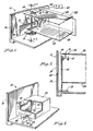
- FIG. 1 there is shown a portion of an electronic postage meter 11 having a secured exterior housing 10.
- the housing 10 is designed to provide security from tampering including unauthorized access to the interior of the housing where accounting information is retained in a nonvolatile memory 24 and where microprocessor control circuits 30 may be actuated as will be explained in further detail later (FIG. 4). Further, the housing provides protection from electro- magnetic interference for the electronic components contained within housing 10.
- a printed circuit board 22 having the. nonvolatile memory 24 mounted thereon.
- An electrical communication channel 26 from nonvolatile memory 24 is provided on printed circuit board 22 and is shown in the form of lead lines directed toward aperture 20.
- Aperture 20 provides access to communication channel 26 for an electronic probe connector 28 see Fig. 4 which electrically engages communication channel 26 in a male-female connection to provide electrical access to the register of nonvolatile memory 24.
- an electronic postage meter 11 is shown schematically including secured housing 10 within which is enclosedthemicroprocessor control circuits30, nonvolatile memory 24 and power supply 40. External to the housing 10, and in electrical communication therewith through circuit connections 32, 34 and 35, which may include optical isolation circuits, not shown, are keyboard 36, display 38 and postage printer 39, respectively. Although the printer 39 is shown schematically exterior to housing 10, it is to be understood that its control mechanism 66 is located within secure housing 10 to provide tamper-proof security protection therefor. ,
- the power supply 40 supplies various voltage levels to elements of the microprocessor control circuits30, the nonvolatile memory 24, and through 5 volt outlet 52, to other peripheral circuits, not shown, through connections 44, 46, 48, and 50 respectively.
- Electrical connection of power supply 40 to the electronic elements of postage meter 11 is made through switch 56 which connects 58 and 60 in the position shown in FIG. 4.
- Power supply 40 may also be connected to an external power supply 54 through isolation circuit 55.
- Access to nonvolatile memory 24 may be achieved through an auxiliary multiple output communication channel 26 which is accessed through the exterior of housing 10 by electrical probe connector 28.
- probe 28 accesses the read lines only of nonvolatile memory 24 and thus communication channel 26 includes the read lines only for memory 24.
- communication channel 26 includes both the read and the write lines to non-volatile memory 24. This construction permits reading the balance in the registers and thereafter resetting the meter registers to zero.
- aperture 20 in housing 10 is provided by means of a reduced thickness portion of the housing 10.
- the reduced thicknes portion is a portion capable of breaking away to form a break-away door/12d permits access to communication channel 26 located within housing 10.
- Mounted on or formed integrally with break-away door 13 is a mounting member 15 having a lever arm 16 with a V-shaped or hooked portion 17 mounted thereon.
- An actuating member which may be in the form of a wire or flexible rod 19 is mounted securely at one end on circuit board 25 and at the other end on switch 56. Intermediate its ends, the wire 19 is threaded through slot 18 in board 25 and securely around hook portion 17. Opening break-away door 13 draws hook portion 17 downward from the position shown in FIG.
- switch 56 may be in the form of an electromechanical or electrical switch which can only be returned to the closed circuit position shown in FIG. 1 by completely disassembling the meter. Alternatively, switch 56 may simply be a break-away portion of the output line 58 from power supply 40.
- Meter 11 includes housing 10 and mounted therewithin is an inner housing 29 which surrounds aperture 20 and provides tamper-proof protection as well as electromagnetic interference protection for the interior of housing 10.
- A educed thickness portion of housing 10 forms a break-away door 13 and mounted securely on or formed integrally with door 13 is a lever member 21 having an extended portion 27 which projects through an opening 23 in inner housing 29.
- the inner end 27 of member 21 has a hook member formed thereon which engages switch 56. Opening break-away door 13 draws hook member 27 away from switch 56 such that hook end 27 opens switch 56. In this manner the power supply 40 is disengaged from the electronic components of the meter 11.
- opening of door 13 provides access to communication channel 26 (not shown in FIG. 3) so that an externally applied probe 28 can engage communication channel 26 to read out the non-volatile memory 24.
- communication channel 26 does not provide access to the nonvolatile memory 24 which would permit unauthorized writing in of new or changed information to the accounting registers.
- the contents of memory register 24 can be read by accessing door 13 in order to transfer the postal balance in the inoperative meter to a replacement meter, thereby avoiding a lengthy delay during repair of the malfunctioning meter.
- an electronic postage meter has been provided with a security system such that transfer of the accounting information contained in the nonvolatile memory can be made at the postal service location without the lengthy delay usually required while the meter is returned to a repair location and then taken to the postal service for recharging and resetting. It will be seen that this access is permitted in a secure fashion which disables the meter for further use thereby preventing unauthorized changing of the contents of the nonvolatile memory or operation of the meter and postage printer.
- an auxiliary communication channel containing read access lines to the nonvolatile memory. Access to this communication channel is provided through a sealed access aperture or door, which provides tampering and electromagnetic interference protection, but is designed for operation on a single occasion only. Access through the door precludes further normal meter operation by deactivating the meter in such a manner that reactivation is not possible without destruction of the meter housing.
- the customer has immediate access to his postage funds while protection of the data and prevention of unauthorized alteration of the postage funds balance as well as unauthorized use of the meter and in particular its printing mechanism is achieved.
- an electronic postage meter having a secured housing which encloses a nonvolatile memory containing accounting information and an access aperture designed for use on a single occasion.
- the aperture is an integral part of the secured housing and provides both tamper proof security and electromagnetic interference protection as does the secured housing itself.
- Use of the one time access aperture which may be in the form of a break-away door, permits electronic probing of the nonvolatile memory for reading out the accounting information contained therein but precludes providing means for writing additional or changed information into the nonvolatile memory and provides a visible indication that the aperture has been accessed. Further, the opening of the access aperture disables the meter from further normal operation.
Abstract
Description
- This application relates generally to an accessible secured housing for an electronic device, for example an electronic metering device such as an electronic postage meter.
- Electronic postage meters are well known devices for imprinting postage impressions of desired value directly on an article to be mailed or on an adherent tape to be affixed to the article. Such meters commonly include a keyboard for the entry of postage information to be printed, a display for displaying postage information to be printed, one or more microprocessors and peripheral circuits for controlling various meter functions and operations including the entry of data to the registers and activation of a printing mechanism, an electronic accounting device including internal memory registers for maintining accounting information, and a printing mechanism for imprinting the postage information. The accounting information maintained in the memory registers may include a control total representing the total amount of postage paid for, an ascending balance representing the total amount of postage printed and expended and a descending balance representing the total balance of postage remaining.
- Prior to using a meter, a user must purchase an amount of postage from the postal service. The term "postal service" as used herein means either a governmental postal service or an authorized private carrier. In one typical system, a postal service agent or employee alters the contents of the internal memory register to reflect the amount of postage paid tor and sets or increases the control total and descending balance so as to reflect the amount of postage purchased. In order to use the meter, the user selects a postage value to be imprinted and activates the postage printing mechanism. Tne postage meter may be used continuously until the descending balance reaches a predetermined minimum (i.e. until the postage paid for has been exhausted or has reached a pre-determined minimum threshold value required for operation).
- Since the accounting information represents the equivalent of money, it is apparent that stringent security safeguards are necessary to protect this information. In particular, the security safeguards must ensure that all postage printed must be paid for. For this reason the printing actuating mechanism and the accounting registers are located within a secured housing and access thereto is restricted, in general, to postal service employees or to employees at the manufacturer's special meter repair facility. Additional security in electronic postage meters is provided by programmed safeguards employed in the operation of the system. Such safeguards are shown and described in U.S. Patent No. 3,938,095 issued February 10, 1976 and U.S. Patent No. 3,978,457 issued August 31, 1976, both of which patents are assigned to the assignee of the present invention. European patent publication No. 0019515 published November 26, 1980 also describes such safeguards.
- Electronic postage meters inherently rely for their operation on continuous electric power, and interruption in such power including either a loss of electric power, a decrease in the electric power below a required minimum line voltage or a fluctuation in the power can threaten the security of electronic postage meters in at least two ways. First, the electronic memory registers which retain the accounting information usually require continuous power for their operation and thus a power interruption may result in a loss of accounting information. Second, a power interruption can affect the operation of the logic and control circuit elements within the meter such that their operation is erratic thus resulting in entry of erroneous data to the memory registers. Accordingly, as a further security safeguard, a separate and redundant set of memory registers in the form of a nonvolatile memory is provided, which nonvolatile memory does not rely on continuous external power and thus retains the accounting information even though a power interruption occurs. Such nonvolatile memories may be inherently nonvolatile such as a semiconductor bubble memory or may rely on an auxiliary power source such as a battery. In this manner accounting data is maintained even in the event of a power interruption. As noted, the accounting information has a value similar to that of money and thus the accounting data maintained in the nonvolatile memory is maintained in a secured housing and may be accessed only by postal employees or employees of the manufacturer/s meter repair facility during normal operation.
- When the descending balance reaches a pre-determined minimum, the postage meter must be recharged, that is control data and descending register data must be reset to reflect an increase in the amount of postage paid for.
- This is done at the postal service facility by postal service agents or employees or by a remote resetting mechanism such as that shown and described in U.S. Patent No. 4,097,923 issued June 27, 1978 and assigned to the assignee of the present invention.
- The postal service requires access to the registers in the memory for resetting or for periodic inspection of the meter. In particular, when a meter is taken out of service, it is necessary to read the registers to determine the balance available and to properly refund or credit the remaining baiance of funds to the customer. In addition, it is desired to clear the descending register to zero under these circumstances. As a result, there is a problem if a malfunction in a meter occurs in circuits peripheral to the nonvolatile memory such as the microprocessor control circuits, power supply or isolation circuits. In such a case, immediate access to the memory registers is not possible at the postal service location and the meter must be returned to a repair facility for read out of the postage funds balance from the register. As a result a substantial period of time elapses during which the customer does not have access to the postage funds he has paid for and which remain on his control total and descending balance in the registers contained in his inoperative meter. It would be desirable to access the accounting information in the event of such a malfunction and transfer it immediately into a replacement meter thus providing the customer with substantially immediate access to his postage funds balance and to thereafter render the meter inoperative.
- According to one aspect of the invention, there is provided an electronic calculating device characterized by: a secure housing which provides protection from tampering and electromagnetic interference for the contents of the housing, which contents include a non-volatile memory for containing accounting information; an access door in the housing providing access to the non-volatile memory, the access door being constructed such that opening the door once prevents its . use as a door again; and means operatively associated with the door for disabling the device from further operation upon opening of the door while permitting electrical communication with the non-volatile memory.
- According to a further aspect of the invention, there is provided an electronic calculating device characterized by: memory means for having accounting information registered therein; a control means for calculating said accounting information and entering the information into the memory means; a power supply for providing power to the control means; a switch means having a first position in which an electrical connection is provided between the power supply and the control means and a second position in which the power supply is disconnected from the control means, the switch means being in the first position during normal operation of the calculating device; a secured housing enclosing the memory means, the control means, and the switch means and preventing access thereto during normal operation of the calculating device; an aperture in the housing permitting access to the memory means to read out accounting information registered therein; and a removable door covering the aperture, the arrangement being such that removal of the door from the aperture moves the switch means from the first position to the second position to disconnect the control means from the power supply and thereby to disable the calculating device from further normal operation while permitting readout of the accounting information through the aperture.
- According to a further aspect of the invention, there is provided an electronic calculating device characterized by: nonvolatile memory means for having accounting information registered therein; a control means for calculating the accounting information and entering the information into the nonvolatile memory means; a power supply for providing power to the control means; a two position electrical switchmeans having a first switch position which provides a completed circuit from the power supply to the control means and a second switch position in which the circuit from the power supply to the control means is disconnected, the switch means being in the first position during normal operation of the calculating device; a secured housing enclosing the non-volatile memory means, the control means and the switch means and preventing access thereto during normal operation of the calculating device; an access aperture in the housing permitting access to the nonvolatile memory to read out accounting information registered therein; and a removable door covering the aperture, wherein removal of the door from the access aperture causes the switch means to move from the first position to the second position to disconnect the control means from the power supply thereby disabling the calculating device from further normal operation.
- According to a further aspect of the invention, there is provided an electronic calculating device characterized by: nonvolatile memory means for having postage funds accounting information registered therein; a control means for calculating the accounting information and entering the information into the nonvolatile memory; a power supply for providing power to the control means; a two position electrical switch means having a first switch position which provides a completed circuit from the power supply to the control means and a second switch position in which the circuit from the power supply to the control means is disconnected, the switch means being in the first position during normal operation of the postage meter; a secured housing enclosing the nonvolatile memory means, the control means and the switch means and preventing access thereto during normal operation of the device; a door formed in the housing and interconnected with the switch; and an access aperture formed when the door is removed permitting access to the nonvolatile memory means to read out postage funds accounting information registered therein, wherein removal of the door moves the means from the first position to the second position to disconnect the control means from the power supply thereby disabling the device from further normal operation while permitting read out of the postage funds accounting information from the memory means through the aperture.
- For a better understanding of the invention, and to show how the same may be carried into effect, reference will now be made, by way of example, to the accompanying drawings, in which:
- Fig. 1 is a perspective, partically broken, view of one embodiment of the present invention;
- Fig. 2 is a section of Fig. 1 taken on line 2-2;
- Fig. 3 is a perspective, partically broken view of another embodiment of the present invention; and
- Fig. 4 is a schematic showing of the circuit emplyoed in an embodiment of this invention suitable for a postage meter.
- Referring now to Figs. 1 and 2, there is shown a portion of an
electronic postage meter 11 having a securedexterior housing 10. Thehousing 10 is designed to provide security from tampering including unauthorized access to the interior of the housing where accounting information is retained in anonvolatile memory 24 and wheremicroprocessor control circuits 30 may be actuated as will be explained in further detail later (FIG. 4). Further, the housing provides protection from electro- magnetic interference for the electronic components contained withinhousing 10. - Mounted within housing 1U is a printed
circuit board 22 having the.nonvolatile memory 24 mounted thereon. Anelectrical communication channel 26 fromnonvolatile memory 24 is provided on printedcircuit board 22 and is shown in the form of lead lines directed towardaperture 20. Aperture 20 provides access tocommunication channel 26 for anelectronic probe connector 28 see Fig. 4 which electrically engagescommunication channel 26 in a male-female connection to provide electrical access to the register ofnonvolatile memory 24. - Referring to FIG. 4, an
electronic postage meter 11 is shown schematically including securedhousing 10 within which is enclosedthemicroprocessor control circuits30,nonvolatile memory 24 andpower supply 40. External to thehousing 10, and in electrical communication therewith throughcircuit connections keyboard 36,display 38 andpostage printer 39, respectively. Although theprinter 39 is shown schematically exterior tohousing 10, it is to be understood that itscontrol mechanism 66 is located withinsecure housing 10 to provide tamper-proof security protection therefor. , - As shown in FIG. 4, the
power supply 40 supplies various voltage levels to elements of the microprocessor control circuits30, thenonvolatile memory 24, and through 5volt outlet 52, to other peripheral circuits, not shown, throughconnections power supply 40 to the electronic elements ofpostage meter 11 is made throughswitch 56 which connects 58 and 60 in the position shown in FIG. 4.Power supply 40 may also be connected to anexternal power supply 54 throughisolation circuit 55. - Access to
nonvolatile memory 24 may be achieved through an auxiliary multipleoutput communication channel 26 which is accessed through the exterior ofhousing 10 byelectrical probe connector 28. In a preferred embodiment,probe 28 accesses the read lines only ofnonvolatile memory 24 and thuscommunication channel 26 includes the read lines only formemory 24. Thus accessing ofcommunication channel 26 byprobe 28 permits readout of the contents of the registers ofnonvolatile memory 24 only, while the capability of writing in or changing the information contained innonvolatile memories 24 is precluded when accessingmemory 24 throughprobe 28. Under certain circumstances where other security measures permit, an alternate embodiment may be desirable in whichcommunication channel 26 includes both the read and the write lines to non-volatilememory 24. This construction permits reading the balance in the registers and thereafter resetting the meter registers to zero. - Referring to FIGS. 1 and 2,
aperture 20 inhousing 10 is provided by means of a reduced thickness portion of thehousing 10. The reduced thicknes portion is a portion capable of breaking away to form a break-away door/12d permits access tocommunication channel 26 located withinhousing 10. Mounted on or formed integrally with break-awaydoor 13 is a mountingmember 15 having alever arm 16 with a V-shaped or hookedportion 17 mounted thereon. An actuating member which may be in the form of a wire or flexible rod 19 is mounted securely at one end oncircuit board 25 and at the other end onswitch 56. Intermediate its ends, the wire 19 is threaded throughslot 18 inboard 25 and securely aroundhook portion 17. Opening break-awaydoor 13 drawshook portion 17 downward from the position shown in FIG. 1, thereby movingswitch 56 to an open circuit position thereby disengagingmemory 24 frompower supply 40. If additional security is desired, opening ofdoor 13 can be made to moveswitch 56 to a grounded position (as shown in FIG. 4), thereby disengagingpower supply 40 from the electronic components of themeter 11 and disabling the meter. In addition, breaking away ofdoor 13 provides a visual indication that the meter has been accessed.Switch 56 may be in the form of an electromechanical or electrical switch which can only be returned to the closed circuit position shown in FIG. 1 by completely disassembling the meter. Alternatively, switch 56 may simply be a break-away portion of theoutput line 58 frompower supply 40. - Referring to FIG. 3 a second emboaiment of the invention is illustrated.
Meter 11 includeshousing 10 and mounted therewithin is aninner housing 29 which surroundsaperture 20 and provides tamper-proof protection as well as electromagnetic interference protection for the interior of housing 10.A =educed thickness portion ofhousing 10 forms a break-awaydoor 13 and mounted securely on or formed integrally withdoor 13 is alever member 21 having an extendedportion 27 which projects through anopening 23 ininner housing 29. Theinner end 27 ofmember 21 has a hook member formed thereon which engagesswitch 56. Opening break-awaydoor 13 drawshook member 27 away fromswitch 56 such thathook end 27 opens switch 56. In this manner thepower supply 40 is disengaged from the electronic components of themeter 11. - In both the FIG. 1 and FIG. 3 embodiments opening of
door 13 provides access to communication channel 26 (not shown in FIG. 3) so that an externally appliedprobe 28 can engagecommunication channel 26 to read out thenon-volatile memory 24. As shown,communication channel 26 does not provide access to thenonvolatile memory 24 which would permit unauthorized writing in of new or changed information to the accounting registers. - When a mulfunction of the
postage meter 11 is encountered,the contents ofmemory register 24 can be read by accessingdoor 13 in order to transfer the postal balance in the inoperative meter to a replacement meter, thereby avoiding a lengthy delay during repair of the malfunctioning meter. - In recapitulation, it will be seen that an electronic postage meter has been provided with a security system such that transfer of the accounting information contained in the nonvolatile memory can be made at the postal service location without the lengthy delay usually required while the meter is returned to a repair location and then taken to the postal service for recharging and resetting. It will be seen that this access is permitted in a secure fashion which disables the meter for further use thereby preventing unauthorized changing of the contents of the nonvolatile memory or operation of the meter and postage printer.
- Accordingly, an auxiliary communication channel is provided containing read access lines to the nonvolatile memory. Access to this communication channel is provided through a sealed access aperture or door, which provides tampering and electromagnetic interference protection, but is designed for operation on a single occasion only. Access through the door precludes further normal meter operation by deactivating the meter in such a manner that reactivation is not possible without destruction of the meter housing. Thus, the customer has immediate access to his postage funds while protection of the data and prevention of unauthorized alteration of the postage funds balance as well as unauthorized use of the meter and in particular its printing mechanism is achieved.
- Briefly stated, and in accordance with one embodiment of the present invention, there is provided an electronic postage meter having a secured housing which encloses a nonvolatile memory containing accounting information and an access aperture designed for use on a single occasion. The aperture is an integral part of the secured housing and provides both tamper proof security and electromagnetic interference protection as does the secured housing itself. Use of the one time access aperture, which may be in the form of a break-away door, permits electronic probing of the nonvolatile memory for reading out the accounting information contained therein but precludes providing means for writing additional or changed information into the nonvolatile memory and provides a visible indication that the aperture has been accessed. Further, the opening of the access aperture disables the meter from further normal operation.
- It will be understood that, although the present invention is described in conjunction with a preferred electronic postage meter embodiment, the invention is applicable to other electronic calculating devices employing a secured housing enclosing and preventing access to an electronic control circuit and nonvolatile memory containing accounting data such as voting machines, parimutual machines, and electronic franking machines.
- It is therefore evident that there has been provided in accordance with the present invention a security system for an electronic device that fully satisfies the objects, aims and advantages set forth above. While this invention has been described in conjunction with specific embodiments thereof, it is evident that many alternatives, modifications and variations will be apparent to those skilled in the art. Accordingly, it is intended to embrace all such alternatives, modifications and variations that follow within the scope of the appended claims.
Claims (12)
Applications Claiming Priority (2)
| Application Number | Priority Date | Filing Date | Title |
|---|---|---|---|
| US06/399,594 US4507744A (en) | 1982-07-19 | 1982-07-19 | Accessible housing for electronic system |
| US399594 | 1982-07-19 |
Publications (3)
| Publication Number | Publication Date |
|---|---|
| EP0099571A2 true EP0099571A2 (en) | 1984-02-01 |
| EP0099571A3 EP0099571A3 (en) | 1986-05-14 |
| EP0099571B1 EP0099571B1 (en) | 1988-11-30 |
Family
ID=23580146
Family Applications (1)
| Application Number | Title | Priority Date | Filing Date |
|---|---|---|---|
| EP83107065A Expired EP0099571B1 (en) | 1982-07-19 | 1983-07-19 | Housing for electronic device such as a postage meter |
Country Status (5)
| Country | Link |
|---|---|
| US (1) | US4507744A (en) |
| EP (1) | EP0099571B1 (en) |
| JP (1) | JPS5936885A (en) |
| CA (1) | CA1214557A (en) |
| DE (1) | DE3378600D1 (en) |
Cited By (5)
| Publication number | Priority date | Publication date | Assignee | Title |
|---|---|---|---|---|
| FR2580842A1 (en) * | 1985-04-19 | 1986-10-24 | Roneo Alcatel Ltd | TRANSPORT OF SECURITY INFORMATION BETWEEN ELECTRONIC STATIONS |
| GB2184692A (en) * | 1985-12-26 | 1987-07-01 | Pitney Bowes Inc | Postage accounting devices and methods |
| US4760532A (en) * | 1985-12-26 | 1988-07-26 | Pitney Bowes Inc. | Mailing system with postage value transfer and accounting capability |
| EP0645740A1 (en) * | 1993-09-24 | 1995-03-29 | Neopost Industrie | Franking machine comprising a security locking circuit |
| EP0933739A2 (en) * | 1998-01-30 | 1999-08-04 | Neopost Limited | Tamper detection |
Families Citing this family (15)
| Publication number | Priority date | Publication date | Assignee | Title |
|---|---|---|---|---|
| AU572006B2 (en) * | 1984-10-04 | 1988-04-28 | Alcolator Ltd. | Apparatus for estimating body alcohol concentration |
| US4713756A (en) * | 1985-02-28 | 1987-12-15 | Westinghouse Electric Corp. | Non-volatile memory device for a programmable controller |
| US5389738A (en) * | 1992-05-04 | 1995-02-14 | Motorola, Inc. | Tamperproof arrangement for an integrated circuit device |
| US6049813A (en) * | 1993-02-26 | 2000-04-11 | Intermec Ip Corp. | Portable work station-type data collection system |
| US5496990A (en) * | 1993-12-01 | 1996-03-05 | Gillieron; Christian | Versatile locking mechanism for postage meters |
| US6161758A (en) * | 1995-02-23 | 2000-12-19 | Ncr Corporation | Modular bar code scanner and scale assembly |
| US5689098A (en) * | 1995-05-26 | 1997-11-18 | Ascom Hasler Mailing Systems Ag | Postage meter with improved postal lock |
| US5932119A (en) | 1996-01-05 | 1999-08-03 | Lazare Kaplan International, Inc. | Laser marking system |
| US7152047B1 (en) | 2000-05-24 | 2006-12-19 | Esecure.Biz, Inc. | System and method for production and authentication of original documents |
| US7162035B1 (en) | 2000-05-24 | 2007-01-09 | Tracer Detection Technology Corp. | Authentication method and system |
| US7089420B1 (en) | 2000-05-24 | 2006-08-08 | Tracer Detection Technology Corp. | Authentication method and system |
| DE10114528A1 (en) * | 2001-03-21 | 2002-10-10 | Francotyp Postalia Ag | Secure housing for an electronic device |
| US8171567B1 (en) | 2002-09-04 | 2012-05-01 | Tracer Detection Technology Corp. | Authentication method and system |
| US7995196B1 (en) | 2008-04-23 | 2011-08-09 | Tracer Detection Technology Corp. | Authentication method and system |
| EP3933566A4 (en) * | 2019-02-28 | 2022-10-12 | LG Electronics Inc. | Digital device and control method therefor |
Citations (6)
| Publication number | Priority date | Publication date | Assignee | Title |
|---|---|---|---|---|
| US3882291A (en) * | 1974-02-14 | 1975-05-06 | Park Ohio Industries Inc | Mechanical interlock mechanism for an electrical cabinet |
| US3938095A (en) * | 1971-11-04 | 1976-02-10 | Pitney-Bowes, Inc. | Computer responsive postage meter |
| US3978457A (en) * | 1974-12-23 | 1976-08-31 | Pitney-Bowes, Inc. | Microcomputerized electronic postage meter system |
| US4180856A (en) * | 1977-07-29 | 1979-12-25 | Pitney Bowes Inc. | Electronic postage metering system |
| DE3023427A1 (en) * | 1979-06-28 | 1981-01-08 | Gretag Ag | MOBILE DATA KEEPER |
| US4280180A (en) * | 1979-10-30 | 1981-07-21 | Pitney Bowes Inc. | Electronic postage meter having field resettable control values |
Family Cites Families (2)
| Publication number | Priority date | Publication date | Assignee | Title |
|---|---|---|---|---|
| US4310754A (en) * | 1976-07-14 | 1982-01-12 | Pitney Bowes Inc. | Communication means with transducer physically spaced from interior wall of secure housing |
| US4424573A (en) * | 1981-02-26 | 1984-01-03 | Pitney Bowes Inc. | System for entering a postage meter serial number into a nonvolatile memory from an external channel after assembly of the meter |
-
1982
- 1982-07-19 US US06/399,594 patent/US4507744A/en not_active Expired - Lifetime
-
1983
- 1983-07-18 CA CA000432629A patent/CA1214557A/en not_active Expired
- 1983-07-19 DE DE8383107065T patent/DE3378600D1/en not_active Expired
- 1983-07-19 JP JP58131774A patent/JPS5936885A/en active Pending
- 1983-07-19 EP EP83107065A patent/EP0099571B1/en not_active Expired
Patent Citations (6)
| Publication number | Priority date | Publication date | Assignee | Title |
|---|---|---|---|---|
| US3938095A (en) * | 1971-11-04 | 1976-02-10 | Pitney-Bowes, Inc. | Computer responsive postage meter |
| US3882291A (en) * | 1974-02-14 | 1975-05-06 | Park Ohio Industries Inc | Mechanical interlock mechanism for an electrical cabinet |
| US3978457A (en) * | 1974-12-23 | 1976-08-31 | Pitney-Bowes, Inc. | Microcomputerized electronic postage meter system |
| US4180856A (en) * | 1977-07-29 | 1979-12-25 | Pitney Bowes Inc. | Electronic postage metering system |
| DE3023427A1 (en) * | 1979-06-28 | 1981-01-08 | Gretag Ag | MOBILE DATA KEEPER |
| US4280180A (en) * | 1979-10-30 | 1981-07-21 | Pitney Bowes Inc. | Electronic postage meter having field resettable control values |
Cited By (10)
| Publication number | Priority date | Publication date | Assignee | Title |
|---|---|---|---|---|
| FR2580842A1 (en) * | 1985-04-19 | 1986-10-24 | Roneo Alcatel Ltd | TRANSPORT OF SECURITY INFORMATION BETWEEN ELECTRONIC STATIONS |
| GB2184692A (en) * | 1985-12-26 | 1987-07-01 | Pitney Bowes Inc | Postage accounting devices and methods |
| US4760532A (en) * | 1985-12-26 | 1988-07-26 | Pitney Bowes Inc. | Mailing system with postage value transfer and accounting capability |
| GB2184692B (en) * | 1985-12-26 | 1991-03-13 | Pitney Bowes Inc | Postage accounting devices and methods |
| EP0645740A1 (en) * | 1993-09-24 | 1995-03-29 | Neopost Industrie | Franking machine comprising a security locking circuit |
| FR2710435A1 (en) * | 1993-09-24 | 1995-03-31 | Neopost Ind | Franking machine with a security locking circuit. |
| US5486973A (en) * | 1993-09-24 | 1996-01-23 | Neopost Industrie | Postage meter including a safety locking circuit |
| EP0933739A2 (en) * | 1998-01-30 | 1999-08-04 | Neopost Limited | Tamper detection |
| EP0933739A3 (en) * | 1998-01-30 | 2000-08-09 | Neopost Limited | Tamper detection |
| US6515574B1 (en) | 1998-01-30 | 2003-02-04 | Neopost Limited | Tamper detection |
Also Published As
| Publication number | Publication date |
|---|---|
| US4507744A (en) | 1985-03-26 |
| EP0099571A3 (en) | 1986-05-14 |
| JPS5936885A (en) | 1984-02-29 |
| CA1214557A (en) | 1986-11-25 |
| EP0099571B1 (en) | 1988-11-30 |
| DE3378600D1 (en) | 1989-01-05 |
Similar Documents
| Publication | Publication Date | Title |
|---|---|---|
| US4507744A (en) | Accessible housing for electronic system | |
| US4421977A (en) | Security system for electronic device | |
| US4302821A (en) | Interposer control for electronic postage meter | |
| US4240030A (en) | Intelligent electric utility meter | |
| US3938095A (en) | Computer responsive postage meter | |
| US5920850A (en) | Metering system with automatic resettable time lockout | |
| CA1180120A (en) | Electronic postage meter with weak memory indication | |
| US5526271A (en) | Franking machine | |
| GB2063163A (en) | Electronic postage meter having field resettable control values | |
| US5206812A (en) | Franking machine | |
| US4524426A (en) | Electronic postage meter controllable by mailing machine | |
| US6098032A (en) | System for providing early warning preemptive postal equipment replacement | |
| US4549281A (en) | Electronic postage meter having keyboard entered combination for recharging | |
| EP0516403B1 (en) | Method of remote diagnostics for franking machines | |
| US4283721A (en) | Electronic postage meter having check date warning | |
| CA1150840A (en) | Postage meter having interactive arithmetic operation capability | |
| US4584647A (en) | Electronic postage meter with a ring counter | |
| EP0086396B2 (en) | Postage meter system | |
| USRE31875E (en) | Computer responsive postage meter | |
| US20020002544A1 (en) | Method and apparatus for user-sealing of secured postage printing equipment | |
| CA1147468A (en) | Electronic postage meter having keyboard entered combination for recharging | |
| EP0285390B1 (en) | Franking machine | |
| US4266222A (en) | Electronic postage meter having reset base warning | |
| US20020049683A1 (en) | Process for preventing frauds with regard to a taxi equipped with an electronic taximeter | |
| CA1061466A (en) | Computer responsive postage meter |
Legal Events
| Date | Code | Title | Description |
|---|---|---|---|
| PUAI | Public reference made under article 153(3) epc to a published international application that has entered the european phase |
Free format text: ORIGINAL CODE: 0009012 |
|
| AK | Designated contracting states |
Designated state(s): BE CH DE FR GB LI NL SE |
|
| PUAL | Search report despatched |
Free format text: ORIGINAL CODE: 0009013 |
|
| AK | Designated contracting states |
Kind code of ref document: A3 Designated state(s): BE CH DE FR GB LI NL SE |
|
| RAP1 | Party data changed (applicant data changed or rights of an application transferred) |
Owner name: PITNEY BOWES INC. |
|
| 17P | Request for examination filed |
Effective date: 19860930 |
|
| 17Q | First examination report despatched |
Effective date: 19870708 |
|
| GRAA | (expected) grant |
Free format text: ORIGINAL CODE: 0009210 |
|
| AK | Designated contracting states |
Kind code of ref document: B1 Designated state(s): BE CH DE FR GB LI NL SE |
|
| REF | Corresponds to: |
Ref document number: 3378600 Country of ref document: DE Date of ref document: 19890105 |
|
| ET | Fr: translation filed | ||
| PLBI | Opposition filed |
Free format text: ORIGINAL CODE: 0009260 |
|
| 26 | Opposition filed |
Opponent name: FRANCOTYP- POSTALIA GMBH Effective date: 19890811 |
|
| NLR1 | Nl: opposition has been filed with the epo |
Opponent name: FRANCOTYP- POSTALIA GMBH |
|
| PLAB | Opposition data, opponent's data or that of the opponent's representative modified |
Free format text: ORIGINAL CODE: 0009299OPPO |
|
| R26 | Opposition filed (corrected) |
Opponent name: FRANCOTYP- POSTALIA GMBH Effective date: 19890811 |
|
| PLBN | Opposition rejected |
Free format text: ORIGINAL CODE: 0009273 |
|
| STAA | Information on the status of an ep patent application or granted ep patent |
Free format text: STATUS: OPPOSITION REJECTED |
|
| 27O | Opposition rejected |
Effective date: 19911010 |
|
| NLR2 | Nl: decision of opposition | ||
| PGFP | Annual fee paid to national office [announced via postgrant information from national office to epo] |
Ref country code: FR Payment date: 19940613 Year of fee payment: 12 |
|
| PGFP | Annual fee paid to national office [announced via postgrant information from national office to epo] |
Ref country code: SE Payment date: 19940614 Year of fee payment: 12 |
|
| PGFP | Annual fee paid to national office [announced via postgrant information from national office to epo] |
Ref country code: CH Payment date: 19940615 Year of fee payment: 12 |
|
| PGFP | Annual fee paid to national office [announced via postgrant information from national office to epo] |
Ref country code: GB Payment date: 19940620 Year of fee payment: 12 |
|
| PGFP | Annual fee paid to national office [announced via postgrant information from national office to epo] |
Ref country code: DE Payment date: 19940623 Year of fee payment: 12 |
|
| PGFP | Annual fee paid to national office [announced via postgrant information from national office to epo] |
Ref country code: BE Payment date: 19940705 Year of fee payment: 12 |
|
| PGFP | Annual fee paid to national office [announced via postgrant information from national office to epo] |
Ref country code: NL Payment date: 19940731 Year of fee payment: 12 |
|
| EAL | Se: european patent in force in sweden |
Ref document number: 83107065.1 |
|
| PG25 | Lapsed in a contracting state [announced via postgrant information from national office to epo] |
Ref country code: GB Effective date: 19950719 |
|
| PG25 | Lapsed in a contracting state [announced via postgrant information from national office to epo] |
Ref country code: SE Effective date: 19950720 |
|
| PG25 | Lapsed in a contracting state [announced via postgrant information from national office to epo] |
Ref country code: LI Effective date: 19950731 Ref country code: CH Effective date: 19950731 Ref country code: BE Effective date: 19950731 |
|
| BERE | Be: lapsed |
Owner name: PITNEY BOWES INC. Effective date: 19950731 |
|
| PG25 | Lapsed in a contracting state [announced via postgrant information from national office to epo] |
Ref country code: NL Effective date: 19960201 |
|
| REG | Reference to a national code |
Ref country code: CH Ref legal event code: PL |
|
| GBPC | Gb: european patent ceased through non-payment of renewal fee |
Effective date: 19950719 |
|
| NLV4 | Nl: lapsed or anulled due to non-payment of the annual fee |
Effective date: 19960201 |
|
| PG25 | Lapsed in a contracting state [announced via postgrant information from national office to epo] |
Ref country code: DE Effective date: 19960402 |
|
| EUG | Se: european patent has lapsed |
Ref document number: 83107065.1 |
|
| PG25 | Lapsed in a contracting state [announced via postgrant information from national office to epo] |
Ref country code: FR Effective date: 19960430 |
|
| REG | Reference to a national code |
Ref country code: FR Ref legal event code: ST |
|
| REG | Reference to a national code |
Ref country code: FR Ref legal event code: ST |
|
| REG | Reference to a national code |
Ref country code: FR Ref legal event code: ST |
|
| PLAB | Opposition data, opponent's data or that of the opponent's representative modified |
Free format text: ORIGINAL CODE: 0009299OPPO |