EP0100210A2 - Coefficient of performance measuring device - Google Patents
Coefficient of performance measuring device Download PDFInfo
- Publication number
- EP0100210A2 EP0100210A2 EP83304237A EP83304237A EP0100210A2 EP 0100210 A2 EP0100210 A2 EP 0100210A2 EP 83304237 A EP83304237 A EP 83304237A EP 83304237 A EP83304237 A EP 83304237A EP 0100210 A2 EP0100210 A2 EP 0100210A2
- Authority
- EP
- European Patent Office
- Prior art keywords
- motor
- compressor
- measure
- mechanical vapor
- coefficient
- Prior art date
- Legal status (The legal status is an assumption and is not a legal conclusion. Google has not performed a legal analysis and makes no representation as to the accuracy of the status listed.)
- Withdrawn
Links
Images


Classifications
-
- G—PHYSICS
- G01—MEASURING; TESTING
- G01L—MEASURING FORCE, STRESS, TORQUE, WORK, MECHANICAL POWER, MECHANICAL EFFICIENCY, OR FLUID PRESSURE
- G01L3/00—Measuring torque, work, mechanical power, or mechanical efficiency, in general
- G01L3/26—Devices for measuring efficiency, i.e. the ratio of power output to power input
-
- F—MECHANICAL ENGINEERING; LIGHTING; HEATING; WEAPONS; BLASTING
- F25—REFRIGERATION OR COOLING; COMBINED HEATING AND REFRIGERATION SYSTEMS; HEAT PUMP SYSTEMS; MANUFACTURE OR STORAGE OF ICE; LIQUEFACTION SOLIDIFICATION OF GASES
- F25B—REFRIGERATION MACHINES, PLANTS OR SYSTEMS; COMBINED HEATING AND REFRIGERATION SYSTEMS; HEAT PUMP SYSTEMS
- F25B2500/00—Problems to be solved
- F25B2500/19—Calculation of parameters
Definitions
- COP coefficient of performance
- a coefficient of performance measuring device for a mechanical vapor-compression system having a motor, a compressor driven by said motor, coil means, and fluid expansion means connected together to form said system, the device being characterized by a power transducer to measure the power supplied to said motor, temperature sensors to measure respectively temperatures of the inlet and outlet of said compressor and the inlet and outlet of said fluid expansion means and a processor to store losses typical of said motor, to store the pressure versus enthalpy characteristics of the mechanical vapor-compression system under test, to store the temperature versus entropy characteristics of the mechanical vapor-compression system under test, and to receive output signals of the temperature sensors, said processor being operable to continuously determine the coefficient of performance for said system as said system is operating.
- a mechanical vapor-compression system 10 may be an air conditioning system for a building, or a heat pump for a building.
- the changeover mechanism for reversing of the system to create a heat pump has not been shown as it is not directly material to the present invention.
- the mechanical vapor-compression system 10 includes an electrically operated motor 11, a compressor 12 driven by motor 11, an outlet 13, and an inlet 14.
- the outlet 13 is connected by a pipe 15 to a coil 16.
- the outside coil is connected by a pipe 17 to a fluid expansion valve 20.
- the fluid expansion valve 20 is connected by a pipe 21 to a coil 22.
- the refrigerant circuit for the system 10 is completed by a pipe 23 which connects the coil 22 to the inlet 14 of the compressor 12.
- Coil 16 the fluid expansion valve 20, the compressor 12, its drive motor 11, and the outlet 13, and the inlet 14 of the compressor 12 are shown as enclosed in a housing 24 that typically would be exterior to a building 25 to be heated or cooled by the system.
- the coil 22 and the piping 21 and 23 that connects the expansion valve 20 and the inlet 14 of the refrigerant circuit to the compressor 12 would be enclosed within the building 25,
- a coefficient of performance (COP) measuring device 30 is connected by a plurality of electrical conductors (33 to 38) to sensors that measure temperature within the system, and by conductor 32 to a power transducer 31.
- the conductor 33 is connected to a temperature sensor 43 at the inlet 14 of the compressor 12.
- the conductor 34 is connected to a temperature sensor 44 physically mounted on the coil 22 of the mechanical vapor-compression system.
- the conductor 35 is connected to temperature sensor 45 at the outlet side of the fluid expansion valve 20.
- the conductor 36 is connected to a temperature sensor 46 connected at the inlet side of the fluid expansion valve 20.
- the conductor 37 is connected to a temperature sensor 47 attached in a heat exchange relationship to the surface of the coil 16.
- the system is completed by the conductor 38 being connected to a temperature sensor 48 at the outlet 13 of the compressor 20.
- the six temperature sensors can be any type of temperature sensor capable of being attached, clamped or mounted on the system under test. The sensors provide an electrical signal that can be measured.
- the device 30 can be connected to the mechanical vapor-compression system 10 to measure parameters of that system without the need to break into the refrigeration piping to measure any specific flow or pressure as a parameter of the operation.
- the sensors 43 to 48 are merely temperature sensors which can be mounted in good heat exchange relationship to the surfaces of the mechanical vapor-compression system 10.
- the sensor 31 is a power transducer capable of measuring the power being supplied electrically to the motor 11. This could be a clamp-on type of ammeter, or other power measuring device.
- only one connection is made within the building 25 and that is to coil 22. In certain cases the temperature of the coils 22 and 16 are not needed, and thus all the connections can be made within the housing 24 exterior of the building. This allows the device 30 to be connected to the system without the need to gain access to the building in which the system provides climate control.
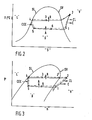
- FIGS 2 and 3 show the pertinent thermodynamic states for evaluating the COP of a mechanical vapor-compression system on both a temperature-entropy (T-s) and a pressure-enthalpy (P-h) diagram.
- T-s temperature-entropy
- P-h pressure-enthalpy
- Points 3, 5 and 6 are located within the Saturation dome D, point 4 being on the saturated liquid line SL and points 1 and 2 being located within the superheated vapor phase V, separated from dome D by the saturated vapor line SV.
- Arrows R and A denote heat rejection and heat absorption respectively
- arrow CEE denotes a constant enthalpy expansion line
- arrow CL denotes casing loss and arrow C compression.
- the dashed cycle line denotes an ideal system in which there are no viscous pressure losses
- the continuous cycle line denotes the system with such losses.
- the system coefficient of performance of the mechanical vapor-compression system is defined as the ratio of the heat rejected to the total work input for heating, and as the ratio of the heat absorbed to the total work input for cooling or: where:
- the COP of the refrigerant flow circuit is: where:
- the compressor work (w ) is: where:
- the total electrical power input to the system is given by:
- a microprocessor 62 (shown in Figure 4) will have the relevant properties of the common refrigerants stored in its memory. Thus, with a single selector switch (not shown), the user can address the appropriate tables for the refrigerant that is under study. In the ideal system (no viscous pressure losses; no subcooling and no superheat), we can use the temperatures at states 1, 2, 4 and 5 directly to generate the relevant enthalpies.
- sensor at state 4 will sense the temperature of a saturated liquid or a subcooled liquid. If state 4 were a saturated liquid, then:
- the microprocessor can determine the enthalpy according to an expression in the form of equation (19). If state 4 is a subcooled liquid, then theoretically:
- the motor efficiency relates the power input measured to the actual power delivered to the shaft driving the compressor, it is essential that the valve input to the microprocessor be representative of the actual motor efficiency. Therefore, as was the case with the jacket heat loss, a survey of numerous compressor manufacturers can provide this data and have it stored in the microprocessor so that, upon selection of a particular mechanical vapor-compression system, the appropriate motor efficiency will be chosen for use in the COP calculations.
- the sensors 43, 44, 45, 46, 47, 48 and 31 provide inputs to an analog to digital card 60.
- This card is connected by a multi-pin ribbon cable 61 to the microprocessor 62 which may be a Motorola 1A microprocessor known as a 6802 which has a 1K RAM and a 4K PROM memory for storage of information as indicated.
- the microprocessor 62 is connected by a multi-pin power cable 63 to a power supply 64 that is capable of supplying the microprocessor and electronics with the correct power. Power input to the power supply 64 is shown at conductors 65 and 66 and are of conventional design.
- a keyboard and display board 70 is provided for input and output of data from the COP device 30 and is interconnected by a multi-pin ribbon 71 to the analog to digital card 60 and by multi-pin ribbon cable 72 to the input ports of the microprocessor 62.
- This microprocessor arrangement provides the device 30 with the ability to store the power loss characteristics of the motor, the pressure versus enthalpy characteristics of the mechanical vapor-compression system under test, and the temperature versus entropy characteristics of the mechanical vapor-compression system under test.
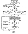
- the COP meter 30 flow chart is disclosed in Figure 5.
- the parameters are initialized (INIT) and at 81 the registers are.;cleared (CLR REGS).
- the output of 81 is fed to a check start initialization device 82 (INIT?) which can provide a no indication "N" at 83, or can continue on "Y” with the sequence at 84. If the sequence is continued at 84, the system checks whether in the heating or cooling made (H/C?) at 85. The appropriate mode is verified by the check of the coefficient of performance modes (COP?) at 86 and 87 for heating and cooling. The modes are properly selected and the system flows on to 88 where the selection of the appropriate refrigerant data (SEL DATA) is checked.
- the sensors that is the temperature sensors and the power transducer means
- a real time clock ((I/P 31,43-48, CLK).
- CAC information calculations based on the operational mode are performed at 91.
- the instantaneous COP is available, it can be displayed at 93 or further processed in a check cycle pattern (CYC PATT) 94 which then indicated a steady state and displays it at 95.
- the above described device is relatively inexpensive to build and is capable of on-site measurement, giving instantaneous measurements of the specific coefficient of performance, and does not interrupt the system operation. Unlike prior devices suggested for this application, it is not merely diagnostic in nature, nor does it give only a relative coefficient of performance indication. Rather, it gives an absolute value of the specific operating condition of a heat pump or a vapor-compression system used typically in a residential or commercial cooling application.
Abstract
Description
- To measure the coefficient of performance (COP) of a mechanical vapor-compression refrigeration system, two parameters must be known. These parameters are the input power, and the heat rejected (in the case of heating) or the heat absorbed (in the case of cooling). Currently, manufacturers test mechanical vapor-compression systems by measuring input power directly with a power transducer or indirectly with an ammeter, and by measuring the heat rejected or absorbed with a large environmental chamber. This method allows accurate COP measurement; however, it does not lend itself to application in the field, whether in the research laboratory or at a specific site, such as a home in which a heat pump or air conditioning system of the vapor-compression type is installed.
- The need to measure the COP of an air conditioning system or a heat pump has been recognized and is becoming more and more important with the widespread use of heat pumps as an energy efficient approach to heating and cooling. Attempts to provide measurements of the COP have been undertaken by measurements of certain temperatures at a specific insta- kllation, but these measurements allow for only a relative coefficient of performance to be provided. The relative coefficient of performance provides a measure only of whether the efficienty of the particular vapor-compression system is increasing or is decreasing, but is incapable of delivering a specific COP for the system.
- According to the present invention, there is provided a coefficient of performance measuring device for a mechanical vapor-compression system having a motor, a compressor driven by said motor, coil means, and fluid expansion means connected together to form said system, the device being characterized by a power transducer to measure the power supplied to said motor, temperature sensors to measure respectively temperatures of the inlet and outlet of said compressor and the inlet and outlet of said fluid expansion means and a processor to store losses typical of said motor, to store the pressure versus enthalpy characteristics of the mechanical vapor-compression system under test, to store the temperature versus entropy characteristics of the mechanical vapor-compression system under test, and to receive output signals of the temperature sensors, said processor being operable to continuously determine the coefficient of performance for said system as said system is operating.
- An embodiment of the present invention will now be described, by way of example, with reference to the accompanying drawings, in which:-
- Figure 1 is a block diagram of a mechanical vapor-compression system with the COP meter of the present invention attached;
- Figure 2 is a typical temperature-entropy curve for a mechanical vapor-compression system;
- Figure 3 is a typical pressure-enthalpy curve for a mechanical vapor-compression system;
- Figure 4 is a block diagram of a microprocessor used in the device of the invention, and;
- Figure 5 is a flow chart showing the basic operation of the device.
- Referring to the drawings, a mechanical vapor-
compression system 10 may be an air conditioning system for a building, or a heat pump for a building. The changeover mechanism for reversing of the system to create a heat pump has not been shown as it is not directly material to the present invention. The mechanical vapor-compression system 10 includes an electrically operatedmotor 11, acompressor 12 driven bymotor 11, anoutlet 13, and aninlet 14. Theoutlet 13 is connected by a pipe 15 to acoil 16. The outside coil is connected by apipe 17 to afluid expansion valve 20. Thefluid expansion valve 20 is connected by apipe 21 to acoil 22. The refrigerant circuit for thesystem 10 is completed by apipe 23 which connects thecoil 22 to theinlet 14 of thecompressor 12. -
Coil 16, thefluid expansion valve 20, thecompressor 12, itsdrive motor 11, and theoutlet 13, and theinlet 14 of thecompressor 12 are shown as enclosed in a housing 24 that typically would be exterior to a building 25 to be heated or cooled by the system. Thecoil 22 and thepiping expansion valve 20 and theinlet 14 of the refrigerant circuit to thecompressor 12 would be enclosed within the building 25, - A coefficient of performance (COP) measuring
device 30 is connected by a plurality of electrical conductors (33 to 38) to sensors that measure temperature within the system, and byconductor 32 to apower transducer 31. Theconductor 33 is connected to atemperature sensor 43 at theinlet 14 of thecompressor 12. Theconductor 34 is connected to atemperature sensor 44 physically mounted on thecoil 22 of the mechanical vapor-compression system. Theconductor 35 is connected totemperature sensor 45 at the outlet side of thefluid expansion valve 20. Theconductor 36 is connected to atemperature sensor 46 connected at the inlet side of thefluid expansion valve 20. Theconductor 37 is connected to atemperature sensor 47 attached in a heat exchange relationship to the surface of thecoil 16. The system is completed by theconductor 38 being connected to atemperature sensor 48 at theoutlet 13 of thecompressor 20. The six temperature sensors can be any type of temperature sensor capable of being attached, clamped or mounted on the system under test. The sensors provide an electrical signal that can be measured. - As is apparent the
device 30 can be connected to the mechanical vapor-compression system 10 to measure parameters of that system without the need to break into the refrigeration piping to measure any specific flow or pressure as a parameter of the operation. Thesensors 43 to 48 are merely temperature sensors which can be mounted in good heat exchange relationship to the surfaces of the mechanical vapor-compression system 10. Thesensor 31 is a power transducer capable of measuring the power being supplied electrically to themotor 11. This could be a clamp-on type of ammeter, or other power measuring device. Further, it is noted that only one connection is made within the building 25 and that is to coil 22. In certain cases the temperature of thecoils device 30 to be connected to the system without the need to gain access to the building in which the system provides climate control. - Figures 2 and 3 show the pertinent thermodynamic states for evaluating the COP of a mechanical vapor-compression system on both a temperature-entropy (T-s) and a pressure-enthalpy (P-h) diagram. In both figures, six states identified as.1 to 6 are of interest in connection with the development of the theory of operation of the present device.
-
Points points - The system coefficient of performance of the mechanical vapor-compression system is defined as the ratio of the heat rejected to the total work input for heating, and as the ratio of the heat absorbed to the total work input for cooling or:

- COPsh = the system coefficient of performance while heating
- Wt = the total work input including transport pumps and fans
- mr = the mass flow rate of the refrigerant
- h2 and h4 are enthalpies of the refrigerant at
states 2 and 4. - COPsc = the system coefficient of performance while cooling
- h5 is the enthalpy at
state 5 - The COP of the refrigerant flow circuit is:

- COPrh = the refrigerant coefficient of performance while heating;
- h1 is the enthalpy at
state 1 and
- COPrc = the refrigerant coefficient of performance while cooling;
- The compressor work (w ) is:

- Win = power to the motor that drives the compressor (directly measurable with a power transducer),
- n = motor efficiency (a function of load). The work input to the refrigerant (W ) is:


- Qamb = jacket heat loss of the compressor
- Combining equations (5) and (7) gives the refrigerant flow rate through the compressor as:

- The total electrical power input to the system is given by:

- Combining equations (1) and (8):

- Similarly combining equations (2) and (8):

- These equations show that onee the power inputs casing loss and compressor motor efficiency are determined, the system COP can be calculated knowing
states - A microprocessor 62 (shown in Figure 4) will have the relevant properties of the common refrigerants stored in its memory. Thus, with a single selector switch (not shown), the user can address the appropriate tables for the refrigerant that is under study. In the ideal system (no viscous pressure losses; no subcooling and no superheat), we can use the temperatures at
states - For instance, state 4 is saturated, thus:


- Therefore, by using suitably insulated temperature sensors located at the
compressor inlet 14 andoutlet 13, and across thefluid expansion valve 20, the enthalpies atstates - Consider the effect of viscous pressure loss in the evaporator. If a well insulated temperature sensor is installed half-way along the fluid circuit of the condensor,
state 6, we can assume that half of the condenser pressure loss occurs betweenstates - Therefore, since:


- Assuming no significant pressure drop in the superheat region:


- Similarly, it can be shown for viscous pressure loss in the evaporator:

- If one considers the viscous pressure loss of the refrigerant gas in the condenser to be negligible, we may write:


- Therefore, for mechanical vapor-compression systems presumed to have significant viscous pressure losses, the addition of suitably insulated sensors at states.3 and 6 t and the substitution of equations (23) and (26) for equations (16) and (18) respectively, will yield correct results.
- Consider the effect of subcooling. With the system in dynamic operation, sensor at state 4 will sense the temperature of a saturated liquid or a subcooled liquid. If state 4 were a saturated liquid, then:

- Thus, knowing only the temperature of state 4, the microprocessor can determine the enthalpy according to an expression in the form of equation (19). If state 4 is a subcooled liquid, then theoretically:

- However, in the subcooled region, pressure has little or no effect on the enthalpy, thus the enthalpy at state 4 can always be given by equation (27). There is some error introduced due to the assumption on the consistency of the pressure drop mechanism in going from two-phase flow to the superheat region at
state 1. However, at this time it is felt that this error is extremely small and will have little or no effect on the accuracy of the device (for example the pressure drop through the evaporator of a well designed mechanical vapor-compression system will in itself be small). The compressor jacket heat loss can be considered if desired. Essentially, the work input to the shaft during compression that does not go into changing the enthalpy of the refrigerant is dissipated as waste heat. When measuring the COP of the mechanical vapor-compression system based on refrigerant measurements, this energy must be accounted for. Based on data from compressor manufacturers, the microprocessor will be supplied with enough information so the user need only specify the type of compressor and size of the mechanical vapor-compression system for the heat loss term in equations (10) and (11) to be automatically calculated. - Since the motor efficiency relates the power input measured to the actual power delivered to the shaft driving the compressor, it is essential that the valve input to the microprocessor be representative of the actual motor efficiency. Therefore, as was the case with the jacket heat loss, a survey of numerous compressor manufacturers can provide this data and have it stored in the microprocessor so that, upon selection of a particular mechanical vapor-compression system, the appropriate motor efficiency will be chosen for use in the COP calculations.
- Referring now to Figure 4, the
sensors digital card 60. This card is connected by amulti-pin ribbon cable 61 to themicroprocessor 62 which may be a Motorola 1A microprocessor known as a 6802 which has a 1K RAM and a 4K PROM memory for storage of information as indicated. Themicroprocessor 62 is connected by amulti-pin power cable 63 to apower supply 64 that is capable of supplying the microprocessor and electronics with the correct power. Power input to thepower supply 64 is shown atconductors - A keyboard and
display board 70 is provided for input and output of data from theCOP device 30 and is interconnected by amulti-pin ribbon 71 to the analog todigital card 60 and bymulti-pin ribbon cable 72 to the input ports of themicroprocessor 62. This microprocessor arrangement provides thedevice 30 with the ability to store the power loss characteristics of the motor, the pressure versus enthalpy characteristics of the mechanical vapor-compression system under test, and the temperature versus entropy characteristics of the mechanical vapor-compression system under test. - In order to further explain the operation of the present device, the
COP meter 30 flow chart is disclosed in Figure 5. Atblock 80 the parameters are initialized (INIT) and at 81 the registers are.;cleared (CLR REGS). The output of 81 is fed to a check start initialization device 82 (INIT?) which can provide a no indication "N" at 83, or can continue on "Y" with the sequence at 84. If the sequence is continued at 84, the system checks whether in the heating or cooling made (H/C?) at 85. The appropriate mode is verified by the check of the coefficient of performance modes (COP?) at 86 and 87 for heating and cooling. The modes are properly selected and the system flows on to 88 where the selection of the appropriate refrigerant data (SEL DATA) is checked. At 90 the sensors (that is the temperature sensors and the power transducer means) are read as is a real time clock ((I/P 31,43-48, CLK). With this information calculations (CALC) based on the operational mode are performed at 91. At 92, if the instantaneous COP is available, it can be displayed at 93 or further processed in a check cycle pattern (CYC PATT) 94 which then indicated a steady state and displays it at 95. - The above described device is relatively inexpensive to build and is capable of on-site measurement, giving instantaneous measurements of the specific coefficient of performance, and does not interrupt the system operation. Unlike prior devices suggested for this application, it is not merely diagnostic in nature, nor does it give only a relative coefficient of performance indication. Rather, it gives an absolute value of the specific operating condition of a heat pump or a vapor-compression system used typically in a residential or commercial cooling application.

Claims (4)
Applications Claiming Priority (2)
| Application Number | Priority Date | Filing Date | Title |
|---|---|---|---|
| US06/401,993 US4510576A (en) | 1982-07-26 | 1982-07-26 | Specific coefficient of performance measuring device |
| US401993 | 1982-07-26 |
Publications (2)
| Publication Number | Publication Date |
|---|---|
| EP0100210A2 true EP0100210A2 (en) | 1984-02-08 |
| EP0100210A3 EP0100210A3 (en) | 1986-07-30 |
Family
ID=23590103
Family Applications (1)
| Application Number | Title | Priority Date | Filing Date |
|---|---|---|---|
| EP83304237A Withdrawn EP0100210A3 (en) | 1982-07-26 | 1983-07-21 | Coefficient of performance measuring device |
Country Status (4)
| Country | Link |
|---|---|
| US (1) | US4510576A (en) |
| EP (1) | EP0100210A3 (en) |
| JP (1) | JPS59104052A (en) |
| CA (1) | CA1207059A (en) |
Cited By (40)
| Publication number | Priority date | Publication date | Assignee | Title |
|---|---|---|---|---|
| FR2552827A1 (en) * | 1983-10-03 | 1985-04-05 | Bosch Gmbh Robert | HYDROSTATIC MACHINE (PUMP OR MOTOR) |
| GB2251492A (en) * | 1990-10-27 | 1992-07-08 | Air Technology Limited | Compressor monitoring system |
| EP2196740A2 (en) * | 2008-12-11 | 2010-06-16 | Emerson Electric GmbH & Co. OHG | Method for determining the performance of a cooling machine |
| EP2282142A1 (en) * | 2003-06-26 | 2011-02-09 | Carrier Corporation | Control of refrigeration system |
| EP2998667A1 (en) * | 2014-09-17 | 2016-03-23 | Hochschule Biberach | Method and apparatus for evaluating the energy efficiency of a refrigeration machine and/or heat pump |
| EP2447613A3 (en) * | 2010-10-29 | 2016-06-29 | Robert Bosch GmbH | Method for regulating a heat pump assembly |
| CN106839323A (en) * | 2017-02-28 | 2017-06-13 | 青岛海尔空调电子有限公司 | A kind of air-conditioner managing device and the air-conditioner with the managing device |
| CN106871357A (en) * | 2017-02-28 | 2017-06-20 | 青岛海尔空调电子有限公司 | A kind of air-conditioner managing device and the air-conditioner with the managing device |
| CN106949611A (en) * | 2017-02-28 | 2017-07-14 | 青岛海尔空调电子有限公司 | A kind of air-conditioner managing device and the air-conditioner with the managing device |
| CN107314515A (en) * | 2017-08-31 | 2017-11-03 | 广东美的制冷设备有限公司 | Air conditioner and its efficiency computational methods |
| CN107314513A (en) * | 2017-08-31 | 2017-11-03 | 广东美的制冷设备有限公司 | Air conditioner and its efficiency computational methods |
| CN107314514A (en) * | 2017-08-31 | 2017-11-03 | 广东美的制冷设备有限公司 | Air conditioner and its efficiency computational methods |
| CN107328050A (en) * | 2017-08-31 | 2017-11-07 | 广东美的制冷设备有限公司 | Air conditioner and its efficiency computational methods |
| CN107328052A (en) * | 2017-08-31 | 2017-11-07 | 广东美的制冷设备有限公司 | Air conditioner and its efficiency computational methods |
| CN107328038A (en) * | 2017-08-31 | 2017-11-07 | 广东美的制冷设备有限公司 | Air conditioner and its efficiency computational methods |
| CN107328055A (en) * | 2017-08-31 | 2017-11-07 | 广东美的制冷设备有限公司 | Air conditioner and its efficiency computational methods |
| CN107328056A (en) * | 2017-08-31 | 2017-11-07 | 广东美的制冷设备有限公司 | Air conditioner and its efficiency computational methods |
| CN107367037A (en) * | 2017-08-31 | 2017-11-21 | 广东美的制冷设备有限公司 | Air conditioner and its efficiency computational methods |
| CN107388519A (en) * | 2017-08-31 | 2017-11-24 | 广东美的制冷设备有限公司 | Air conditioner and its efficiency computational methods |
| CN107388520A (en) * | 2017-08-31 | 2017-11-24 | 广东美的制冷设备有限公司 | Air conditioner and its efficiency computational methods |
| CN107388515A (en) * | 2017-08-31 | 2017-11-24 | 广东美的制冷设备有限公司 | Air conditioner and its efficiency computational methods |
| CN107388521A (en) * | 2017-08-31 | 2017-11-24 | 广东美的制冷设备有限公司 | Air conditioner and its efficiency computational methods |
| CN107388522A (en) * | 2017-08-31 | 2017-11-24 | 广东美的制冷设备有限公司 | Air conditioner and its efficiency computational methods |
| CN107388512A (en) * | 2017-08-31 | 2017-11-24 | 广东美的制冷设备有限公司 | Air conditioner and its efficiency computational methods |
| CN107388517A (en) * | 2017-08-31 | 2017-11-24 | 广东美的制冷设备有限公司 | Air conditioner and its efficiency computational methods |
| CN107388518A (en) * | 2017-08-31 | 2017-11-24 | 广东美的制冷设备有限公司 | Air conditioner and its efficiency computational methods |
| CN107388523A (en) * | 2017-08-31 | 2017-11-24 | 广东美的制冷设备有限公司 | Air conditioner and its efficiency computational methods |
| CN107490139A (en) * | 2017-08-31 | 2017-12-19 | 广东美的制冷设备有限公司 | Air conditioner and its efficiency computational methods |
| CN107490146A (en) * | 2017-08-31 | 2017-12-19 | 广东美的制冷设备有限公司 | Air conditioner and its efficiency computational methods |
| CN107490147A (en) * | 2017-08-31 | 2017-12-19 | 广东美的制冷设备有限公司 | Air conditioner and its efficiency computational methods |
| CN107490140A (en) * | 2017-08-31 | 2017-12-19 | 广东美的制冷设备有限公司 | Air conditioner and its efficiency computational methods |
| CN107504649A (en) * | 2017-08-31 | 2017-12-22 | 广东美的制冷设备有限公司 | Air conditioner and its efficiency computational methods |
| CN107504651A (en) * | 2017-08-31 | 2017-12-22 | 广东美的制冷设备有限公司 | Air conditioner and its efficiency computational methods |
| CN107514765A (en) * | 2017-08-31 | 2017-12-26 | 广东美的制冷设备有限公司 | Air conditioner and its efficiency computational methods |
| CN107514770A (en) * | 2017-08-31 | 2017-12-26 | 广东美的制冷设备有限公司 | Air conditioner and its efficiency computational methods |
| CN107514758A (en) * | 2017-08-31 | 2017-12-26 | 广东美的制冷设备有限公司 | Air conditioner and its efficiency computational methods |
| CN107514764A (en) * | 2017-08-31 | 2017-12-26 | 广东美的制冷设备有限公司 | Air conditioner and its efficiency computational methods |
| CN107514771A (en) * | 2017-08-31 | 2017-12-26 | 广东美的制冷设备有限公司 | Air conditioner and its efficiency computational methods |
| CN107525240A (en) * | 2017-08-31 | 2017-12-29 | 广东美的制冷设备有限公司 | Air conditioner and its efficiency computational methods |
| CN107576008A (en) * | 2017-08-31 | 2018-01-12 | 广东美的制冷设备有限公司 | Air conditioner and its efficiency computational methods |
Families Citing this family (103)
| Publication number | Priority date | Publication date | Assignee | Title |
|---|---|---|---|---|
| SE439063B (en) * | 1983-06-02 | 1985-05-28 | Henrik Sven Enstrom | PROCEDURE AND DEVICE FOR TESTING AND PERFORMANCE MONITORING IN HEAT PUMPS AND COOLING INSTALLATIONS |
| EP0159152A1 (en) * | 1984-03-26 | 1985-10-23 | Maurice Alan Yates | Protection for hydraulic machines |
| US4574871A (en) * | 1984-05-07 | 1986-03-11 | Parkinson David W | Heat pump monitor apparatus for fault detection in a heat pump system |
| US4768346A (en) * | 1987-08-26 | 1988-09-06 | Honeywell Inc. | Determining the coefficient of performance of a refrigeration system |
| US4885914A (en) * | 1987-10-05 | 1989-12-12 | Honeywell Inc. | Coefficient of performance deviation meter for vapor compression type refrigeration systems |
| US4798055A (en) * | 1987-10-28 | 1989-01-17 | Kent-Moore Corporation | Refrigeration system analyzer |
| US4787554A (en) * | 1988-02-01 | 1988-11-29 | Honeywell Inc. | Firing rate control system for a fuel burner |
| US4811567A (en) * | 1988-03-03 | 1989-03-14 | General Electric Company | Method for testing the operability of a refrigerant system |
| US5020007A (en) * | 1988-03-10 | 1991-05-28 | Wu Samuel C | Method for monitoring the health of physical systems producing waste heat |
| US5009076A (en) * | 1990-03-08 | 1991-04-23 | Temperature Engineering Corp. | Refrigerant loss monitor |
| US5083438A (en) * | 1991-03-01 | 1992-01-28 | Mcmullin Larry D | Chiller monitoring system |
| DE4124363C2 (en) * | 1991-07-23 | 1994-02-03 | Daimler Benz Ag | Procedure for monitoring the refrigerant level in a refrigeration system |
| US5651667A (en) * | 1991-10-11 | 1997-07-29 | Helix Technology Corporation | Cryopump synchronous motor load monitor |
| US5203179A (en) * | 1992-03-04 | 1993-04-20 | Ecoair Corporation | Control system for an air conditioning/refrigeration system |
| US5381669A (en) * | 1993-07-21 | 1995-01-17 | Copeland Corporation | Overcharge-undercharge diagnostic system for air conditioner controller |
| US5666815A (en) * | 1994-11-18 | 1997-09-16 | Cooper Instrument Corporation | Method and apparatus for calculating super heat in an air conditioning system |
| US5628201A (en) * | 1995-04-03 | 1997-05-13 | Copeland Corporation | Heating and cooling system with variable capacity compressor |
| US5623834A (en) * | 1995-05-03 | 1997-04-29 | Copeland Corporation | Diagnostics for a heating and cooling system |
| EP0837309A3 (en) * | 1996-10-18 | 1999-03-10 | SANYO ELECTRIC Co., Ltd. | Method and system for testing performance of refrigeration units |
| US5765378A (en) * | 1996-12-31 | 1998-06-16 | Helix Technology Corporation | Method and apparatus for detecting a loss of differential pressure in a cryogenic refrigerator |
| US6128910A (en) * | 1997-02-06 | 2000-10-10 | Federal Air Conditioning Technologies, Inc. | Diagnostic unit for an air conditioning system |
| KR100286258B1 (en) * | 1998-02-03 | 2001-05-02 | 윤종용 | Method and system for measuring quantity of consumption power to refrigerator |
| CA2284234C (en) * | 1998-10-01 | 2003-09-16 | Samsung Electronics Co., Ltd. | Method and apparatus for predicting power consumption of refrigerator having defrosting heater |
| US6505475B1 (en) | 1999-08-20 | 2003-01-14 | Hudson Technologies Inc. | Method and apparatus for measuring and improving efficiency in refrigeration systems |
| US6272868B1 (en) * | 2000-03-15 | 2001-08-14 | Carrier Corporation | Method and apparatus for indicating condenser coil performance on air-cooled chillers |
| US6532754B2 (en) * | 2001-04-25 | 2003-03-18 | American Standard International Inc. | Method of optimizing and rating a variable speed chiller for operation at part load |
| US6892546B2 (en) * | 2001-05-03 | 2005-05-17 | Emerson Retail Services, Inc. | System for remote refrigeration monitoring and diagnostics |
| US6668240B2 (en) * | 2001-05-03 | 2003-12-23 | Emerson Retail Services Inc. | Food quality and safety model for refrigerated food |
| US6658373B2 (en) * | 2001-05-11 | 2003-12-02 | Field Diagnostic Services, Inc. | Apparatus and method for detecting faults and providing diagnostics in vapor compression cycle equipment |
| US6701725B2 (en) | 2001-05-11 | 2004-03-09 | Field Diagnostic Services, Inc. | Estimating operating parameters of vapor compression cycle equipment |
| US6973410B2 (en) | 2001-05-15 | 2005-12-06 | Chillergy Systems, Llc | Method and system for evaluating the efficiency of an air conditioning apparatus |
| DE10217974B4 (en) * | 2002-04-22 | 2004-09-16 | Danfoss A/S | Method for evaluating an unmeasured operating variable in a refrigeration system |
| DE10217975B4 (en) * | 2002-04-22 | 2004-08-19 | Danfoss A/S | Method for detecting changes in a first media stream of a heat or cold transport medium in a refrigeration system |
| FR2840259B1 (en) * | 2002-05-31 | 2004-08-27 | Valeo Climatisation | VEHICLE AIR CONDITIONING SYSTEM PROVIDED WITH AN ELECTRONIC CONTROL DEVICE |
| DE60309181T2 (en) * | 2002-07-08 | 2007-08-30 | Danfoss A/S | METHOD AND DEVICE FOR DISCOVERING FLASH GAS |
| US6973793B2 (en) * | 2002-07-08 | 2005-12-13 | Field Diagnostic Services, Inc. | Estimating evaporator airflow in vapor compression cycle cooling equipment |
| FR2845035B1 (en) * | 2002-09-27 | 2004-12-24 | Valeo Climatisation | AIR CONDITIONING SYSTEM COMPRISING AN ELECTRONIC CONTROL DEVICE |
| WO2004036170A1 (en) * | 2002-10-15 | 2004-04-29 | Danfoss A/S | A method and a device for detecting an abnormality of a heat exchanger, and the use of such a device |
| US6889173B2 (en) * | 2002-10-31 | 2005-05-03 | Emerson Retail Services Inc. | System for monitoring optimal equipment operating parameters |
| US6713986B1 (en) | 2002-11-26 | 2004-03-30 | Energy Savers International | Controller for air conditioners and heat pumps |
| US8463441B2 (en) | 2002-12-09 | 2013-06-11 | Hudson Technologies, Inc. | Method and apparatus for optimizing refrigeration systems |
| US7490477B2 (en) * | 2003-04-30 | 2009-02-17 | Emerson Retail Services, Inc. | System and method for monitoring a condenser of a refrigeration system |
| AU2008202088B2 (en) * | 2003-04-30 | 2010-11-25 | Emerson Climate Technologies Retail Solutions, Inc. | Predictive maintenance and equipment monitoring for a refrigeration system |
| WO2005022049A2 (en) * | 2003-08-25 | 2005-03-10 | Computer Process Controls, Inc. | Refrigeration control system |
| US20050061008A1 (en) * | 2003-09-24 | 2005-03-24 | A. Ben-Nakhi | Method and apparatus for monitoring an air conditioning / refrigeration unit |
| US7290989B2 (en) * | 2003-12-30 | 2007-11-06 | Emerson Climate Technologies, Inc. | Compressor protection and diagnostic system |
| US7412842B2 (en) | 2004-04-27 | 2008-08-19 | Emerson Climate Technologies, Inc. | Compressor diagnostic and protection system |
| US7275377B2 (en) | 2004-08-11 | 2007-10-02 | Lawrence Kates | Method and apparatus for monitoring refrigerant-cycle systems |
| US8109104B2 (en) * | 2004-08-25 | 2012-02-07 | York International Corporation | System and method for detecting decreased performance in a refrigeration system |
| US20060137369A1 (en) * | 2004-12-27 | 2006-06-29 | Carrier Corporation | Single sensor three-step refrigerant charge indicator |
| US20060138771A1 (en) * | 2004-12-27 | 2006-06-29 | Carrier Corporation | Braze-free connector for joining a pair of flow lines |
| US7712319B2 (en) | 2004-12-27 | 2010-05-11 | Carrier Corporation | Refrigerant charge adequacy gauge |
| US7472557B2 (en) * | 2004-12-27 | 2009-01-06 | Carrier Corporation | Automatic refrigerant charging apparatus |
| US7610765B2 (en) * | 2004-12-27 | 2009-11-03 | Carrier Corporation | Refrigerant charge status indication method and device |
| US20060138772A1 (en) * | 2004-12-27 | 2006-06-29 | Carrier Corporation | Braze-free connector |
| US7552596B2 (en) * | 2004-12-27 | 2009-06-30 | Carrier Corporation | Dual thermochromic liquid crystal temperature sensing for refrigerant charge indication |
| WO2006091521A2 (en) * | 2005-02-21 | 2006-08-31 | Computer Process Controls, Inc. | Enterprise control and monitoring system |
| US7419192B2 (en) * | 2005-07-13 | 2008-09-02 | Carrier Corporation | Braze-free connector utilizing a sealant coated ferrule |
| US7203077B2 (en) * | 2005-07-20 | 2007-04-10 | General Atomics Electronic Systems, Inc. | Resonant charge power supply topology for high pulse rate pulsed power systems |
| US7594407B2 (en) | 2005-10-21 | 2009-09-29 | Emerson Climate Technologies, Inc. | Monitoring refrigerant in a refrigeration system |
| US7752854B2 (en) * | 2005-10-21 | 2010-07-13 | Emerson Retail Services, Inc. | Monitoring a condenser in a refrigeration system |
| US7596959B2 (en) | 2005-10-21 | 2009-10-06 | Emerson Retail Services, Inc. | Monitoring compressor performance in a refrigeration system |
| US7665315B2 (en) * | 2005-10-21 | 2010-02-23 | Emerson Retail Services, Inc. | Proofing a refrigeration system operating state |
| US20070089435A1 (en) * | 2005-10-21 | 2007-04-26 | Abtar Singh | Predicting maintenance in a refrigeration system |
| US7752853B2 (en) | 2005-10-21 | 2010-07-13 | Emerson Retail Services, Inc. | Monitoring refrigerant in a refrigeration system |
| US20070089436A1 (en) * | 2005-10-21 | 2007-04-26 | Abtar Singh | Monitoring refrigerant in a refrigeration system |
| US20070093732A1 (en) * | 2005-10-26 | 2007-04-26 | David Venturi | Vibroacoustic sound therapeutic system and method |
| CN101400955B (en) * | 2006-03-23 | 2012-06-27 | 大金工业株式会社 | Refrigeration system, and analyzer of refrigeration system |
| US8590325B2 (en) * | 2006-07-19 | 2013-11-26 | Emerson Climate Technologies, Inc. | Protection and diagnostic module for a refrigeration system |
| US20080216494A1 (en) | 2006-09-07 | 2008-09-11 | Pham Hung M | Compressor data module |
| US20080066474A1 (en) * | 2006-09-20 | 2008-03-20 | Michael Ramey Porter | Refrigeration system energy efficiency enhancement using microsystems |
| WO2008079108A1 (en) * | 2006-12-20 | 2008-07-03 | Carrier Corporation | Refrigerant charge indication |
| WO2008079111A1 (en) * | 2006-12-20 | 2008-07-03 | Carrier Corporation | Method for determining refrigerant charge |
| US9305405B2 (en) * | 2007-06-26 | 2016-04-05 | Omnitracs, Llc | Reefer fuel tax reporting for the transport industry |
| US20090037142A1 (en) | 2007-07-30 | 2009-02-05 | Lawrence Kates | Portable method and apparatus for monitoring refrigerant-cycle systems |
| US8393169B2 (en) | 2007-09-19 | 2013-03-12 | Emerson Climate Technologies, Inc. | Refrigeration monitoring system and method |
| US9140728B2 (en) | 2007-11-02 | 2015-09-22 | Emerson Climate Technologies, Inc. | Compressor sensor module |
| US8160827B2 (en) | 2007-11-02 | 2012-04-17 | Emerson Climate Technologies, Inc. | Compressor sensor module |
| JP5394047B2 (en) * | 2007-11-26 | 2014-01-22 | 高砂熱学工業株式会社 | Method and apparatus for measuring cooling capacity of air conditioning system by package type air conditioner |
| US20090252845A1 (en) * | 2008-04-03 | 2009-10-08 | Southwick Kenneth J | Collider chamber apparatus and method of use |
| DE102008038429A1 (en) * | 2008-08-19 | 2010-02-25 | Erwin Dietz | Heat pump system operating method for air conditioning e.g. building, involves determining coefficient of performance, performance number, efficiency or analysis of refrigerant based on mass flow of refrigerant |
| US20100187320A1 (en) * | 2009-01-29 | 2010-07-29 | Southwick Kenneth J | Methods and systems for recovering and redistributing heat |
| CN101545880B (en) * | 2009-04-30 | 2011-11-16 | 上海交通大学 | Device for measuring trans-critical cycle heat exchange of CO2-oil mixture |
| BRPI1014993A8 (en) | 2009-05-29 | 2016-10-18 | Emerson Retail Services Inc | system and method for monitoring and evaluating equipment operating parameter modifications |
| US8646286B2 (en) * | 2010-12-30 | 2014-02-11 | Pdx Technologies Llc | Refrigeration system controlled by refrigerant quality within evaporator |
| CA2934860C (en) | 2011-02-28 | 2018-07-31 | Emerson Electric Co. | Residential solutions hvac monitoring and diagnosis |
| US9759465B2 (en) | 2011-12-27 | 2017-09-12 | Carrier Corporation | Air conditioner self-charging and charge monitoring system |
| US8964338B2 (en) | 2012-01-11 | 2015-02-24 | Emerson Climate Technologies, Inc. | System and method for compressor motor protection |
| US9480177B2 (en) | 2012-07-27 | 2016-10-25 | Emerson Climate Technologies, Inc. | Compressor protection module |
| US9310439B2 (en) | 2012-09-25 | 2016-04-12 | Emerson Climate Technologies, Inc. | Compressor having a control and diagnostic module |
| US9417638B2 (en) * | 2012-12-20 | 2016-08-16 | Automotive Research & Testing Center | Intelligent thermostatic control method and device for an air conditioner blowing cold and hot air |
| US9958190B2 (en) | 2013-01-24 | 2018-05-01 | Advantek Consulting Engineering, Inc. | Optimizing energy efficiency ratio feedback control for direct expansion air-conditioners and heat pumps |
| US9574810B1 (en) | 2013-01-24 | 2017-02-21 | Advantek Consulting Engineering, Inc. | Optimizing energy efficiency ratio feedback control for direct expansion air-conditioners and heat pumps |
| FR3001527B1 (en) * | 2013-01-28 | 2017-08-11 | Schneider Electric Ind Sas | METHOD FOR DIAGNOSING A HEATING, VENTILATION AND AIR CONDITIONING MACHINE |
| US9551504B2 (en) | 2013-03-15 | 2017-01-24 | Emerson Electric Co. | HVAC system remote monitoring and diagnosis |
| CA2904734C (en) | 2013-03-15 | 2018-01-02 | Emerson Electric Co. | Hvac system remote monitoring and diagnosis |
| US9803902B2 (en) | 2013-03-15 | 2017-10-31 | Emerson Climate Technologies, Inc. | System for refrigerant charge verification using two condenser coil temperatures |
| US9765979B2 (en) | 2013-04-05 | 2017-09-19 | Emerson Climate Technologies, Inc. | Heat-pump system with refrigerant charge diagnostics |
| WO2016118914A1 (en) * | 2015-01-22 | 2016-07-28 | Aquanomix, Llc | Water system efficiency |
| US11867417B2 (en) | 2017-02-09 | 2024-01-09 | James Eric Taylor | On-site controller for an HVAC system |
| US11105689B2 (en) * | 2017-03-09 | 2021-08-31 | Keithley Instruments, Llc | Temperature and heat map system |
| CN107367032A (en) * | 2017-08-31 | 2017-11-21 | 广东美的制冷设备有限公司 | Air conditioner and its efficiency computational methods |
| CN112856873A (en) * | 2021-01-18 | 2021-05-28 | 苏州龙雨电子设备有限公司 | Equipment for accurately controlling gas temperature |
Citations (3)
| Publication number | Priority date | Publication date | Assignee | Title |
|---|---|---|---|---|
| US4146085A (en) * | 1977-10-03 | 1979-03-27 | Borg-Warner Corporation | Diagnostic system for heat pump |
| DE2543237B2 (en) * | 1975-09-27 | 1979-10-18 | Werner Dipl.-Ing. 8886 Wittislingen Hoefflinger | Method and device for thermodynamic efficiency measurement on hydrostatic displacement machines |
| US4381549A (en) * | 1980-10-14 | 1983-04-26 | Trane Cac, Inc. | Automatic fault diagnostic apparatus for a heat pump air conditioning system |
Family Cites Families (13)
| Publication number | Priority date | Publication date | Assignee | Title |
|---|---|---|---|---|
| US3082951A (en) * | 1953-07-01 | 1963-03-26 | Univ Columbia | Method for calculating performance of refrigeration apparatus |
| US3555251A (en) * | 1967-12-06 | 1971-01-12 | Honeywell Inc | Optimizing system for a plurality of temperature conditioning apparatuses |
| US3707851A (en) * | 1970-10-28 | 1973-01-02 | Mach Ice Co | Refrigeration system efficiency monitor |
| US3736765A (en) * | 1972-01-05 | 1973-06-05 | Gen Electric | Appliance including electric diagnosis means |
| US3873817A (en) * | 1972-05-03 | 1975-03-25 | Westinghouse Electric Corp | On-line monitoring of steam turbine performance |
| US3946573A (en) * | 1974-08-22 | 1976-03-30 | Whirlpool Corporation | Electrical diagnostic system for refrigeration apparatus |
| US4038061A (en) * | 1975-12-29 | 1977-07-26 | Heil-Quaker Corporation | Air conditioner control |
| US4114448A (en) * | 1976-09-13 | 1978-09-19 | Merritt Joseph E | Servicing apparatus |
| US4186563A (en) * | 1978-04-24 | 1980-02-05 | General Electric Company | Cooling efficiency meter circuit for an air conditioner |
| US4217761A (en) * | 1978-09-28 | 1980-08-19 | Cornaire James L | Heat pump output indicator |
| US4306293A (en) * | 1979-08-30 | 1981-12-15 | Marathe Sharad M | Energy monitoring system |
| JPS5685507A (en) * | 1979-12-17 | 1981-07-11 | Hitachi Ltd | Monitoring method of performance of steam turbine plant |
| US4432232A (en) * | 1982-05-18 | 1984-02-21 | The United States Of America As Represented By The United States Department Of Energy | Device and method for measuring the coefficient of performance of a heat pump |
-
1982
- 1982-07-26 US US06/401,993 patent/US4510576A/en not_active Expired - Lifetime
-
1983
- 1983-07-21 EP EP83304237A patent/EP0100210A3/en not_active Withdrawn
- 1983-07-25 CA CA000433137A patent/CA1207059A/en not_active Expired
- 1983-07-26 JP JP58136653A patent/JPS59104052A/en active Pending
Patent Citations (3)
| Publication number | Priority date | Publication date | Assignee | Title |
|---|---|---|---|---|
| DE2543237B2 (en) * | 1975-09-27 | 1979-10-18 | Werner Dipl.-Ing. 8886 Wittislingen Hoefflinger | Method and device for thermodynamic efficiency measurement on hydrostatic displacement machines |
| US4146085A (en) * | 1977-10-03 | 1979-03-27 | Borg-Warner Corporation | Diagnostic system for heat pump |
| US4381549A (en) * | 1980-10-14 | 1983-04-26 | Trane Cac, Inc. | Automatic fault diagnostic apparatus for a heat pump air conditioning system |
Cited By (43)
| Publication number | Priority date | Publication date | Assignee | Title |
|---|---|---|---|---|
| FR2552827A1 (en) * | 1983-10-03 | 1985-04-05 | Bosch Gmbh Robert | HYDROSTATIC MACHINE (PUMP OR MOTOR) |
| GB2251492A (en) * | 1990-10-27 | 1992-07-08 | Air Technology Limited | Compressor monitoring system |
| GB2251492B (en) * | 1990-10-27 | 1994-04-20 | Air Technology Limited | Compressor monitoring system |
| EP2282142A1 (en) * | 2003-06-26 | 2011-02-09 | Carrier Corporation | Control of refrigeration system |
| EP2196740A2 (en) * | 2008-12-11 | 2010-06-16 | Emerson Electric GmbH & Co. OHG | Method for determining the performance of a cooling machine |
| EP2196740A3 (en) * | 2008-12-11 | 2010-09-15 | Emerson Electric GmbH & Co. OHG | Method for determining the performance of a cooling machine |
| US8775123B2 (en) | 2008-12-11 | 2014-07-08 | Emerson Climate Technologies Gmbh | Method for determination of the coefficient of performanace of a refrigerating machine |
| EP2447613A3 (en) * | 2010-10-29 | 2016-06-29 | Robert Bosch GmbH | Method for regulating a heat pump assembly |
| EP2998667A1 (en) * | 2014-09-17 | 2016-03-23 | Hochschule Biberach | Method and apparatus for evaluating the energy efficiency of a refrigeration machine and/or heat pump |
| CN106839323A (en) * | 2017-02-28 | 2017-06-13 | 青岛海尔空调电子有限公司 | A kind of air-conditioner managing device and the air-conditioner with the managing device |
| CN106871357A (en) * | 2017-02-28 | 2017-06-20 | 青岛海尔空调电子有限公司 | A kind of air-conditioner managing device and the air-conditioner with the managing device |
| CN106949611A (en) * | 2017-02-28 | 2017-07-14 | 青岛海尔空调电子有限公司 | A kind of air-conditioner managing device and the air-conditioner with the managing device |
| CN107367037A (en) * | 2017-08-31 | 2017-11-21 | 广东美的制冷设备有限公司 | Air conditioner and its efficiency computational methods |
| CN107388517A (en) * | 2017-08-31 | 2017-11-24 | 广东美的制冷设备有限公司 | Air conditioner and its efficiency computational methods |
| CN107314514A (en) * | 2017-08-31 | 2017-11-03 | 广东美的制冷设备有限公司 | Air conditioner and its efficiency computational methods |
| CN107328050A (en) * | 2017-08-31 | 2017-11-07 | 广东美的制冷设备有限公司 | Air conditioner and its efficiency computational methods |
| CN107328052A (en) * | 2017-08-31 | 2017-11-07 | 广东美的制冷设备有限公司 | Air conditioner and its efficiency computational methods |
| CN107328038A (en) * | 2017-08-31 | 2017-11-07 | 广东美的制冷设备有限公司 | Air conditioner and its efficiency computational methods |
| CN107328055A (en) * | 2017-08-31 | 2017-11-07 | 广东美的制冷设备有限公司 | Air conditioner and its efficiency computational methods |
| CN107328056A (en) * | 2017-08-31 | 2017-11-07 | 广东美的制冷设备有限公司 | Air conditioner and its efficiency computational methods |
| CN107314515A (en) * | 2017-08-31 | 2017-11-03 | 广东美的制冷设备有限公司 | Air conditioner and its efficiency computational methods |
| CN107388519A (en) * | 2017-08-31 | 2017-11-24 | 广东美的制冷设备有限公司 | Air conditioner and its efficiency computational methods |
| CN107388520A (en) * | 2017-08-31 | 2017-11-24 | 广东美的制冷设备有限公司 | Air conditioner and its efficiency computational methods |
| CN107388515A (en) * | 2017-08-31 | 2017-11-24 | 广东美的制冷设备有限公司 | Air conditioner and its efficiency computational methods |
| CN107388521A (en) * | 2017-08-31 | 2017-11-24 | 广东美的制冷设备有限公司 | Air conditioner and its efficiency computational methods |
| CN107388522A (en) * | 2017-08-31 | 2017-11-24 | 广东美的制冷设备有限公司 | Air conditioner and its efficiency computational methods |
| CN107388512A (en) * | 2017-08-31 | 2017-11-24 | 广东美的制冷设备有限公司 | Air conditioner and its efficiency computational methods |
| CN107314513A (en) * | 2017-08-31 | 2017-11-03 | 广东美的制冷设备有限公司 | Air conditioner and its efficiency computational methods |
| CN107388518A (en) * | 2017-08-31 | 2017-11-24 | 广东美的制冷设备有限公司 | Air conditioner and its efficiency computational methods |
| CN107388523A (en) * | 2017-08-31 | 2017-11-24 | 广东美的制冷设备有限公司 | Air conditioner and its efficiency computational methods |
| CN107490139A (en) * | 2017-08-31 | 2017-12-19 | 广东美的制冷设备有限公司 | Air conditioner and its efficiency computational methods |
| CN107490146A (en) * | 2017-08-31 | 2017-12-19 | 广东美的制冷设备有限公司 | Air conditioner and its efficiency computational methods |
| CN107490147A (en) * | 2017-08-31 | 2017-12-19 | 广东美的制冷设备有限公司 | Air conditioner and its efficiency computational methods |
| CN107490140A (en) * | 2017-08-31 | 2017-12-19 | 广东美的制冷设备有限公司 | Air conditioner and its efficiency computational methods |
| CN107504649A (en) * | 2017-08-31 | 2017-12-22 | 广东美的制冷设备有限公司 | Air conditioner and its efficiency computational methods |
| CN107504651A (en) * | 2017-08-31 | 2017-12-22 | 广东美的制冷设备有限公司 | Air conditioner and its efficiency computational methods |
| CN107514765A (en) * | 2017-08-31 | 2017-12-26 | 广东美的制冷设备有限公司 | Air conditioner and its efficiency computational methods |
| CN107514770A (en) * | 2017-08-31 | 2017-12-26 | 广东美的制冷设备有限公司 | Air conditioner and its efficiency computational methods |
| CN107514758A (en) * | 2017-08-31 | 2017-12-26 | 广东美的制冷设备有限公司 | Air conditioner and its efficiency computational methods |
| CN107514764A (en) * | 2017-08-31 | 2017-12-26 | 广东美的制冷设备有限公司 | Air conditioner and its efficiency computational methods |
| CN107514771A (en) * | 2017-08-31 | 2017-12-26 | 广东美的制冷设备有限公司 | Air conditioner and its efficiency computational methods |
| CN107525240A (en) * | 2017-08-31 | 2017-12-29 | 广东美的制冷设备有限公司 | Air conditioner and its efficiency computational methods |
| CN107576008A (en) * | 2017-08-31 | 2018-01-12 | 广东美的制冷设备有限公司 | Air conditioner and its efficiency computational methods |
Also Published As
| Publication number | Publication date |
|---|---|
| US4510576A (en) | 1985-04-09 |
| CA1207059A (en) | 1986-07-02 |
| JPS59104052A (en) | 1984-06-15 |
| EP0100210A3 (en) | 1986-07-30 |
Similar Documents
| Publication | Publication Date | Title |
|---|---|---|
| EP0100210A2 (en) | Coefficient of performance measuring device | |
| US6973793B2 (en) | Estimating evaporator airflow in vapor compression cycle cooling equipment | |
| US6701725B2 (en) | Estimating operating parameters of vapor compression cycle equipment | |
| US4878355A (en) | Method and apparatus for improving cooling of a compressor element in an air conditioning system | |
| US6694763B2 (en) | Method for operating a transcritical refrigeration system | |
| JP2997487B2 (en) | Refrigeration apparatus and method for indicating amount of refrigerant in refrigeration apparatus | |
| EP0693663B1 (en) | Air-conditioner using a non-azeotrope refrigerant and having a composition computing unit | |
| US5709094A (en) | Air conditioner control apparatus based on coolant type detection | |
| CN108758903B (en) | Air conditioner and control method thereof | |
| CN101821508A (en) | Variable speed compressor protection system and method | |
| Lumpkin et al. | Two-phase injected and vapor-injected compression: Experimental results and mapping correlation for a R-407C scroll compressor | |
| KR20100108056A (en) | Real time performance evaluation method for ground source heat pump system and evaluation device programming the same | |
| JP3531440B2 (en) | Air conditioner with refrigerant charge determination device and refrigerant charge determination method | |
| JP2000130897A (en) | Method and equipment for determining quantity of encapsulated refrigerant | |
| JP3584274B2 (en) | Refrigerant amount adjustment method and refrigerant amount determination device | |
| JP3560497B2 (en) | Refrigeration compressor test equipment | |
| US11384949B2 (en) | Air conditioner system and control method thereof | |
| Hubacher et al. | Performance measurements of a semi-hermetic carbon dioxide compressor | |
| CA1198905A (en) | Heat pump apparatus and method of operating the same | |
| WO2022180821A1 (en) | Refrigeration cycle device | |
| Domingorena et al. | Performance evaluation of a selected three-ton air-to-air heat pump in the heating mode | |
| Rohleder | Experimental Analysis of Positive Displacement Compressors for Refrigerator Freezer and Air Conditioning Application | |
| WO2023145016A1 (en) | Diagnostic device and refrigeration cycle device having same | |
| KR20220027561A (en) | A turbo chiller | |
| Kush | Compressor performance at high suction temperatures with application to solar heat pumps |
Legal Events
| Date | Code | Title | Description |
|---|---|---|---|
| PUAI | Public reference made under article 153(3) epc to a published international application that has entered the european phase |
Free format text: ORIGINAL CODE: 0009012 |
|
| AK | Designated contracting states |
Designated state(s): BE DE FR GB IT NL SE |
|
| PUAL | Search report despatched |
Free format text: ORIGINAL CODE: 0009013 |
|
| RHK1 | Main classification (correction) |
Ipc: G01M 19/00 |
|
| AK | Designated contracting states |
Kind code of ref document: A3 Designated state(s): BE DE FR GB IT NL SE |
|
| STAA | Information on the status of an ep patent application or granted ep patent |
Free format text: STATUS: THE APPLICATION HAS BEEN WITHDRAWN |
|
| 18W | Application withdrawn |
Withdrawal date: 19861208 |
|
| RIN1 | Information on inventor provided before grant (corrected) |
Inventor name: MACARTHUR, WARD, J. Inventor name: RADOMSKI, JAMES V. |