EP0100859A2 - Game with permanent magnets - Google Patents
Game with permanent magnets Download PDFInfo
- Publication number
- EP0100859A2 EP0100859A2 EP83106485A EP83106485A EP0100859A2 EP 0100859 A2 EP0100859 A2 EP 0100859A2 EP 83106485 A EP83106485 A EP 83106485A EP 83106485 A EP83106485 A EP 83106485A EP 0100859 A2 EP0100859 A2 EP 0100859A2
- Authority
- EP
- European Patent Office
- Prior art keywords
- playing
- permanent magnets
- field
- permanent magnet
- drive
- Prior art date
- Legal status (The legal status is an assumption and is not a legal conclusion. Google has not performed a legal analysis and makes no representation as to the accuracy of the status listed.)
- Granted
Links
Images


Classifications
-
- A—HUMAN NECESSITIES
- A63—SPORTS; GAMES; AMUSEMENTS
- A63H—TOYS, e.g. TOPS, DOLLS, HOOPS OR BUILDING BLOCKS
- A63H33/00—Other toys
- A63H33/26—Magnetic or electric toys
-
- A—HUMAN NECESSITIES
- A63—SPORTS; GAMES; AMUSEMENTS
- A63F—CARD, BOARD, OR ROULETTE GAMES; INDOOR GAMES USING SMALL MOVING PLAYING BODIES; VIDEO GAMES; GAMES NOT OTHERWISE PROVIDED FOR
- A63F7/00—Indoor games using small moving playing bodies, e.g. balls, discs or blocks
- A63F7/0088—Indoor games using small moving playing bodies, e.g. balls, discs or blocks using magnetic power
-
- A—HUMAN NECESSITIES
- A63—SPORTS; GAMES; AMUSEMENTS
- A63F—CARD, BOARD, OR ROULETTE GAMES; INDOOR GAMES USING SMALL MOVING PLAYING BODIES; VIDEO GAMES; GAMES NOT OTHERWISE PROVIDED FOR
- A63F9/00—Games not otherwise provided for
- A63F9/14—Racing games, traffic games, or obstacle games characterised by figures moved by action of the players
Definitions
- the invention relates to a game with permanent magnets according to the preamble of claim 1.
- a magnet designated with permanent magnet 11 is drawn, which is magnetized in the direction of the magnetization axis MA, perpendicular to the base U.
- the permanent magnet can be cylindrical with diameter DD and height HD.
- the magnetic field lines FL are shown schematically, and the north and south poles of the permanent magnet are marked with N and S.
- two further magnets with drive permanent magnets 21 and 22 are recorded. These two magnets can also be cylindrical, with a cylinder diameter DDA, and each have a cylinder height HA.
- FIG. 1b The same permanent magnets as in FIG. 1a are recorded in FIG. 1b, but the two drive permanent magnets 21, 22 are spaced apart from one another in the direction of the magnetization axis MA and symmetrically to the central plane ME by a distance DAM which is somewhat larger than the height HD of the Figure permanent magnet 11 is.
- the course of the field lines FL is also shown here, and it can be seen that this course is at a greater distance, for example in the case of figures Permanent magnets, about the same as in Fig la. Here too. therefore the permanent magnet 11 repelled in the direction P. If one moves to the right in the direction of the coordinate X from the permanent magnet 11 on the central plane ME, the field lines FL first run from top to bottom.
- FIG. 1b there is no guide for the permanent magnet 11 in the figure, and it would tip over and be attracted by one of the two permanent drive magnets 21, 22.
- the two playing field plates 31 and 32 which run parallel to one another and to the central plane ME are present, between which the permanent magnet 11 of the figures can move freely along the central plane ME. Since the distance DSP of the playing field slabs is only slightly larger than the height HD of the permanent magnet, its tipping over is prevented.
- the figure permanent magnet can only move between the playing field plates along the central plane ME.
- This middle level is referred to below as the playing field level.
- the distance DAM between the drive permanent magnets 21 and 22 is normally somewhat greater than the distance DSA from the top of the upper to the underside of the lower field plate.
- the figure permanent magnet 11 is drawn in three different positions relative to the drive permanent magnets 21, 22.
- the figure permanent magnet 11 becomes in the position of FIG. 1c repelled in the direction of the force PAB, in the position of FIG. 1d at the critical distance DKR, it is neither repelled nor attracted, and in the position of FIG. 1, at which the critical distance DKR is undershot, the figure permanent magnet 11 is moved in the direction of FIG Force PAN is attracted and is then held between the two drive permanent magnets 21, 22.
- the permanent magnet is placed in the front part with respect to the normal running direction of the game figure, i.e. according to FIGS. 2a and 2 am near the head of the mouse, which is due to the effect of the repulsive force from the drive permanent magnet and the frictional force of the game part's rear part on the lower one
- the playing field plate removes the playing figure from the permanent magnet in its normal running direction.
- the height of the playing figure is slightly smaller than the distance DSP of the two playing fields.
- the top field plate 32 is made of translucent material, such as acrylic glass.
- the upper permanent drive magnet 21 lies directly above the upper playing field plate 32 and the lower permanent driving magnet 22 below the lower playing field plate, coaxially with one another with the same magnetization axis MA, whose direction of magnetization also corresponds to the figure permanent magnet 11.
- the two drive permanent magnets 21, 22 are rigidly connected to one another via a drive fork with the fork legs 23 and 24, the upper one Magnet at the end of the upper fork leg 23 and the lower magnet at the end of the lower fork leg 24 is fixed and the connection point 28 of the two fork legs is outside the field.
- the drive permanent magnets and the drive fork with the fork legs together form the drive part, which can be moved by hand using the handle 25 parallel to the field level.
- the connection point 28 of the fork legs 23 and 24 consists of the attachments 241 and 242 attached to the lower fork leg 24, to the latter of which the upper fork leg 23 can be plugged in and can be taken along by means of the driving bolt
- the upper fork leg 23 is preferably made of transparent plastic and is held in the operating state by a ferromagnetic plate 231 contained in it by the permanent magnet 243 contained in the attachment 242.
- a round bearing disc 245 is attached, which is rotatably and axially slidably mounted in a guide rail 41.
- the webs 43 are attached to the guide rail with the bolts 42, by means of which the guide rail can be plugged onto the field body 312, by inserting it into the plug-in holes 315 contained therein.
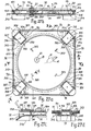
- the lower playing field plate 31 is integrated into the playing field body 312, which has an approximately square shape in view of the playing field level 1 and is supported in the four corners with floor supports 314 against the floor.
- the circular field boundary 101 is also contained in the field body 21, as a result of which the game figures 12 located between the field plates only in the circular region of the field defined by the field boundary Playfield are movable.
- the upper field plate 32 has an approximately square shape in view of the field level, the actual field comprising the circular area enclosed in the square with the field boundary 101 as a circumferential line.
- the upper playing field plate can be inserted into the playing field body 3l21ose and is held at a playing surface distance DSP by a support shoulder 102 and centered by edge strips 313 of the playing field body 31 2 .
- FIGS. 2a and 2b the drive fork with the fork legs 23 and 24 and the guide rail on the left side of the field body 312 are drawn.
- a second guide rail 41 with a drive fork could be plugged into the plug holes 315 on the right side of the field body for a second player.
- this second drive fork with guide rail 41 is shown in the disassembled state from the field body, wherein in FIG. 2c the upper fork leg is shown separated from the lower.
- the drive permanent magnets 21, 22, which can be moved by hand using the handle 25, can take on the role of the cat in the case of cat and mouse play and can also be provided with a cat picture, while the game figure 12 represents the mouse. Of course, a larger number of game characters or mice could be present in field 1 at the same time. If the drive part, which plays the role of the cat, is moved, the game figures represented as mice always have a tendency to flee from the cat, owing to the repulsive effect of the permanent magnets. Only if the drive part 20 is able to get close enough to a play figure, ie at a distance below the critical distance, is this figure held between the drive permanent magnets or caught by the cat. Playing with the permanent magnets can therefore be a ge be a game of skill in which the cat should catch as many mice as possible in the shortest possible time.
- a certain further disadvantage of the embodiment of the game according to FIGS. 2a to 2e lies in the fact that a relatively complex mechanism with a drive fork and guide rail is required for the mechanical coupling of the two drive permanent magnets. Another disadvantage is that the size of the field is limited by this mechanism. In the embodiments described below, these disadvantages are avoided in that the drive permanent magnets are coupled to one another magnetically rather than mechanically.
- the basic mode of operation is described with reference to FIG. 3.
- the upper permanent drive magnet 21 which can be, for example, a cylinder with a cylinder axis MA and height HA.
- the rollers 98 attached to it reduce the friction when the magnet is moved over the field plate.
- a handle 25 for manual operation is attached to the upper magnet.
- the lower permanent drive magnet 22 with the same shape and the same direction of magnetization MA as the upper magnet and like the permanent magnet 11 is attached under the lower playing field plate 31.
- the two permanent drive magnets attract each other, and when the upper permanent anti-vibration magnet 21 is moved by hand using the handle 25 over the upper playing field plate, the lower permanent magnet 22 is taken along by magnetic coupling, and the magnetization axes MA remain essentially coaxial, and the effect of the two permanent magnets on the permanent magnets 11 is the same as that of the figure 2a to 2e described above mechanical coupling of the magnets.
- the barrel attached to both permanent magnets Roll 98 allow movements along the field plates in a coordinate direction with little friction. Embodiments are described below which allow low-friction movements in all directions of the playing field level 1.
- the permanent magnets are hatched vertically in FIG. 3 and the following figures for identification purposes. Due to the magnetic attraction of the two permanent drive magnets, the two playing field plates 31, 32 are bent towards one another, and there is the possibility that the playing figures with the permanent figure magnets 11 are clamped between the plates. In this embodiment, the field plates would have to be sufficiently thick or the field sufficiently small. To avoid this disadvantage, a third central drive permanent magnet 235 can be added, which is placed between the two playing field plates and supports them against each other. The middle drive permanent magnet has other functions as described below. The basic arrangement is shown in Fig. 4.
- All three drive permanent magnets 21, 22, 235 have magnetization axes MA in the same direction, are connected by magnetic coupling and have the same dimensions in the direction of the playing field level 1 and can also be provided with rollers 98 (not shown here) to reduce friction.
- FIG. 4 Such an arrangement according to FIG. 4 has the same effect on a game figure or the figure permanent magnet / uie as was described with reference to FIG. the character is always repelled and never attracted, not even at short distances.
- the central drive permanent magnet 235 has a dimension smaller by at least one side than the lower and upper drive permanent magnets 21, 22 in the direction of the plane of the playing field 1, and becomes a figure permanent magnet 11 located on this side 5a repelled by the drive permanent magnet when it has a greater than the critical distance DKR from it, which is indicated by the arrow PAB drawn on the figure permanent magnet 11. If the figure permanent magnet 11 according to FIG. 5b has the critical distance DKR, it is neither repelled nor attracted. If the figure permanent magnet 11 according to FIG. 5c is smaller than the critical distance DKR from the drive permanent magnet, then he is attracted to or captured by these, which is marked by the arrow PAN.
- the size of the critical distance DKR depends on the size of the difference dimension DM. If the difference dimension DM is large, DKR also becomes large, and it is easier to put on or catch the characters. If the differential dimension DM were so large that the middle permanent magnet disappears, the case described with reference to FIGS. 1 to 1 would be present. With a small differential dimension DM, DKR also becomes small, and tightening or catching the game pieces is made more difficult. For DM + zero, only repulsion of the game permanent magnet occurs, as was shown in FIG. 4.
- the direction of the plane of the playing field 1 is in one of four orthogonal coordinate directions, denoted by + X, -X, + Y, -Y, namely in the coordinate direction denoted by -X as the front the middle drive permanent magnet (235) is offset by a difference DM compared to the upper and lower drive permanent magnets.
- a permanent magnet 11 is repelled at a greater distance and attracted or captured at a small distance.
- a non-magnetic extension 216 is attached to the central drive permanent magnet 235 on the rear side opposite the front, designated + X, and protrudes in the + X direction by a distance DH.
- This approach 216 has the effect that a figure 12 or a permanent magnet 11 is always more than the critical distance away from the drive magnets from the rear side + X, so that it can only be repelled.
- the central drive permanent magnet 235 Transversely to the longitudinal axis X, that is to say in the right-hand side labeled + Y and the left-hand side labeled -Y, the central drive permanent magnet 235 is approximately flush with the upper and lower drive permanent magnets 21 and 22 in the direction perpendicular to the game boards , and on these sides only repulsion of the permanent magnets 11 is possible, as has been described with reference to FIG. 4.
- Non-magnetic lugs 216 could also be attached to the other sides of the permanent magnet 235.
- rollers 98 which are shown in FIG. 8, are omitted.
- FIG. 8 shows an embodiment of drive permanent magnets similar to that in FIG. 5, with rollers 98 for reducing the friction on the game boards.
- the middle drive magnet 235 is supported against the lower and the upper game plate with rollers 98.
- the embodiment according to FIG. 8 with the rollers 98 allows smooth movement only in one direction, designated t X in FIG. 8.
- the drive permanent magnets are supported on the playing field plates by means of the swivel castors 50 instead of by rollers.
- Such castors are known and are used, for example, in mobile serving tables.
- the mode of operation can be seen from FIGS. 9a to 9c.
- the pivot body 53 is rotatably mounted on the pivot axis 52 which is perpendicular to the playing field.
- a running roller 55 running on a playing field plate is rotatably mounted in a roller axis 54, which axis runs parallel to the playing field plane and is distanced from the swiveling axis 52.
- the pivot axis 52 is connected to the flange 51, which in turn is directly or indirectly attached to a drive permanent magnet.
- the bearings could also be designed as ball bearings.
- the embodiment of the game according to FIGS. 10 and 11 corresponds in principle to that of FIGS. 6 and 7, but here swivel castors 50 are attached indirectly to the drive permanent magnets via plastic parts.
- the upper drive permanent magnet 21 is embedded in a plastic part 211, in which four swivel rollers 50 are fixed, which distance the magnet 21 from the upper playing field plate 32.
- the upper drive permanent magnet 21 can be moved by hand using the handle 25.
- the lower permanent magnet 22 is constructed identically, with four swivel castors running on the lower playing field plate and fixed in the plastic part 261, but without a handle.
- the middle lere drive permanent magnet 235 is embedded in a projection 216 formed as a plastic body, in which four castors 50 running on the lower playing field plate 31 and two on the upper playing field plate are fixed.
- the middle part 217 and the rear part 218, the function of which was explained with reference to FIGS. 6 and 7, are also integrated into the plastic projection 216.
- the three permanent drive magnets have a rectangular shape when viewed in the direction of the playing field plate level.
- game figures 12 can only be captured from the front designated by -X. This front side is painted on the plastic part 211 with a cat head 262 in FIG. 11.
- FIGS. 10 and 11 show the state in which a game figure 12 represented as a mouse with the permanent magnet 11 has been captured on the front.
- the captured mouse is ejected according to a first method in such a way that the drive permanent magnets 21, 22, 23 drive with the rear of the mouse first to the edge strips 311, 321 when the field exit 91 is open. Then, with a hook-shaped actuating means 61, the central permanent drive magnet 235 is pressed radially outward in the field, i.e. in Fig. 10 or 11, to the left through a slot 322 in the upper field plate, as a result of which the left edge or the front of the central permanent drive magnet 235, seen perpendicular to the field level, is flush with the left edges of the upper and lower drive permanent magnets and the game figure is vehemently ejected from the field exit 91.
- the drive permanent magnets 21, 22, 235 could also consist of two instead of only one parts, which are connected to each other by a plastic body.
- FIGS. 1 a to 2 a The principle of operation of the game using an upper and a lower drive permanent magnet 21, 22 was explained and shown on the basis of FIGS. 1 a to 2 a that a figure permanent magnet 11 is repelled at a greater distance from the drive permanent magnet and when it falls below a critical distance DKR is attracted to these.
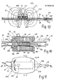
- a similar effect can also be achieved with the correct dimensioning with an arrangement according to FIG. 12, in which only a single one, namely the upper drive permanent magnet 21, acts on the figure permanent magnet 11.
- the course of the magnetic field lines FL of the drive magnet shows that they pass the playing field 1 from top to bottom outside a critical distance DKR and from bottom to top within the critical distance.
- a figure permanent magnet 11 is therefore also repelled outside the distance DKR by the drive permanent magnet and attracted or captured within this distance.
- the effect is not as optimal as in the embodiment from Fig la to le.
- FIG. 13 a mouse is drawn in as game figure 12, which is repelled at a greater distance from the single, upper drive permanent magnet 21 and attracted or captured at a small distance.
- FIG. 14 in addition to the upper, there is also a medium permanent drive magnet 235 which is dragged along by the upper permanent drive magnet 21 by magnetic coupling.
- the mode of action on the figure 12 is similar to the embodiment described with reference to FIGS. 5a to 5c.
- FIG. 15 shows an embodiment of the drive permanent magnet which corresponds to that of the embodiment described below with reference to FIGS. 16 to 18, with the only exception that the lower drive permanent magnet 22 is omitted in FIG.
- the mode of operation is similar to that described below with reference to FIGS. 16 to 18.
- captured game pieces can be ejected by simply lifting the upper drive permanent magnet 21 off the playing field plate 32, after which the captured game piece 12 is repelled by the repelling action of the central magnet 235.
- the playing field can be designed similarly to that shown in FIG. 27.
- drive magnets 21, 235 of FIGS. 13 to 15 can also be provided with swivel rollers 50.
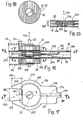
- the drive permanent magnets 21, 22 and 235 have an annular cross section parallel to the playing field level with an inner circle diameter DI.
- a segment of the thickness DM is also cut away in order to make it possible to catch game pieces, as was described above with reference to FIGS. 5a to 5c.
- the handle 25 the upper fork leg 23 and in the bolt 222, the lower fork leg 24 can be fixed in the case of mechanical coupling.
- the embodiment is also suitable for purely magnetic coupling, the fork legs being omitted.
- the circular cross-section is advantageous for centering and driving the middle 235 and lower 22 through the upper 21 drive permanent magnet, and moreover the middle drive permanent magnet 235 can be rotated relative to the other two about the ring axis Z without any inhibiting magnetic forces occurring .
- the attachment 216 made of plastic fastened to the central drive permanent magnet 235 has a special shape, which makes it possible to capture game pieces 12, but makes it considerably more difficult.
- the approach 216 has a throat-like opening with the throat parts 215, a throat width DE and a throat depth DW on the left side, designated catch point 250, on which the segment with depth DM is missing on the central magnet 235.
- the middle part 217 of the attachment 216 projects so far beyond the diameter of the drive permanent magnet that it is not possible to attract play figures here.
- the rear part 218 opposite the catch point 250 also does not permit the attraction of game figures.
- the tail part 219 At the end of the part 218 there is the tail part 219, which is supported on the upper field plate 32. By means of the sheet fastened to the extension 216 and prestressed against the lower playing field plate 31 spring 214, the tail portion 219 is pressed against the top field plate.
- the middle drive permanent magnet 235 is closer to the manually moved upper drive permanent magnet 21 than to the lower drive permanent magnet 22, which is only carried by magnetic coupling, which makes it easier to take along.
- the drive permanent magnets 21, 22 slide over the playing field plates while overcoming frictional forces.
- a swivel roller 50 according to FIG. 19 can be attached to the permanent drive magnets in the interior, which support the magnets against the playing field plates.
- the swivel bearings of these swivel rollers 50 are advantageously designed as ball bearings.
- FIG. 20 A further variant for reducing the friction for the central drive permanent magnet 235 is shown in FIG. 20.
- a bore 525 is provided concentrically with the central magnet axis MA, which is also the magnetic axis, in which two balls 524 with the diameter of half the pitch plate distance DSP are arranged one above the other, practically without play.
- Flexible playing field plates 31, 32 which are pressed against each other by the magnetic forces of the drive permanent magnets, are thus counter-rotating geln supported and the friction when moving the drive permanent magnets is significantly reduced.
- FIGS. 21 to 24 show two game characters 12 which are particularly suitable for the drive permanent magnets 21, 22, 235 of FIGS. 16 to 20.
- FIGS. 21 and 22 show a mouse as a figure 12.
- the figure housing 121 carries the figure permanent magnet 11 on the front and a further additional permanent magnet 11; both with the same directional magnetic axis MA.
- Two castors 99 are attached at the rear and a swivel castor 50 in the front part, the castors running on the lower field plate 31.
- the additional permanent magnet 11 has the purpose of increasing the repulsive effect.
- the game figure 12 according to FIGS. 23a and 23b has a similar structure, but has a slightly differently shaped support body 121 and can carry a coin 93.
- the game figure including the coin is to be caught, which is also only possible here from the front, in the case of the permanent magnet 11.
- FIG. 24 shows a game figure 12 as a replica of a vehicle with wheels 99, and in FIG. 25a, b a game figure 12 as a replica of a sheep.
- the figure permanent magnets 11 are mounted in the front in their normal direction of travel, as a result of which the movement of the game figures in their normal direction of travel, caused by the repulsive action of the drive permanent magnets 21, 22.
- the figure permanent magnets 11 are preferably embedded in a plastic part representing the game figures.
- 26a, b show a round game figure 12 with figure permanent magnets 11 embedded in plastic, which can serve, for example, as a replica of a football.
- Playing field plates 31 and 32 and playing field body 312 are similar to the embodiment as described with reference to FIGS. 2a to e, but are shown somewhat enlarged in FIG. Furthermore, the drive part with the drive fork with the fork legs 23 and 24 and the guide rail 41, which serve for the mechanical coupling of the drive permanent magnets 21, 22, is omitted here.
- the embodiment according to FIG. 27 is only suitable for magnetic coupling of the drive magnets, although guide rails can be coupled to drive forks through the holes 315 contained in the field body 312 if necessary.
- FIG. 27 has some additional devices.
- a closable field exit 91 which leads out of the field to the outside via the elongated lower field plate and its curved ramp 317.
- Such a lockable playing field exit 91 is shown in section in FIG. 27c.
- a flap 325 which can be opened and closed is pivotably mounted in the bearings 329 in the upper field plate 32 about the axis 328, the front flap part 326 projecting through a slot 330 in the upper field plate approximately perpendicular to the field level into the field exit 91 and being able to close it .
- the flap can be opened by means of the handle 327, and the opened state is shown in dotted lines in FIG. 27c.
- the playing field exits 91 are channels which connect directly to the playing field boundary 101, and the flap part 326 lies approximately tangentially to the playing field boundary, as can be seen from FIG. 27a.
- Edge magnets 70 are embedded in the field body 312 on both sides of the field exits 91 and in the vicinity of the field boundary 101 and approximately at the height of the field, the magnetic axes MA of which are oriented in the same direction as those of the drive part and the figures. The edge magnets endeavor to push the playing figures away from the playing field edge towards the center of the playing field, as well as to eject playing figures located in the exit 91 of the playing field when the flap 25 is open.
- Field body 312 with integrated lower field plate 31 and upper field plate 32 and flaps 25 are made of plastic.
- a captured game figure 12 of the type according to FIGS. 21, 22 or 23, 24 is drawn in by the drive permanent magnets 21, 22, 235 of the type from FIGS. 16 to 19 and has been brought into the field exit 91 so that it protrudes .
- the tail part 219 of the central drive permanent magnet is pressed into the notch 324 and prevented from moving to the right, and the figure 12 is ejected to the left via the ramp 317.
- the top two field exits 91 are provided with slots 322 for ejecting the playing figures according to the first method, while the lower two field exits are provided with notches 324 for ejecting according to the second method.
- the game inserts 85 can be placed on the lower 31 when the upper playing field plate 32 is lifted off. They consist, for example, of circular foils or papers 80 or 90 with a diameter smaller than the diameter of the field boundary 101. Objects such as soccer goals 81 or slalom poles 91 can be applied to the foils, the height of which, however, must not exceed the field distance DSP. Drawings 82 or 92 can also be attached to the foils 80 or 90.
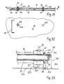
- an 11-meter shoot can be carried out for two players, as is customary in football, as will be briefly explained with reference to FIGS. 31 and 32.
- the shooting player on the right strikes with his permanent drive magnets 21, 22, 235 against the figure 12 simulating the ball, which can be designed according to FIG. 26, and tries to place it in the football goal 81.
- the impact pulse can be conveyed magnetically and / or mechanically to the character.
- the player representing the goalkeeper operates the drive permanent magnets on the left and tries to capture or distract the kicked figure 12.
- the central drive permanent magnet 235 has a smaller diameter than the upper and lower, so that the game figure can be caught between the four lugs 216 shown.
- the character can also be deflected magnetically and / or mechanically. Captured game pieces can be repelled by moving the drive magnets against the soccer goal.
- a game figure 12 which is designed according to FIG. 26, for example, can be guided by means of the drive permanent magnets 21, 22 along a predetermined path 92 through the gates 91 to the goal in the shortest possible time.
- There is no central drive permanent magnet 235 so the player risks catching the character if he approaches the character too quickly, after which he has to start over again according to the rules of the game.
- Captured game figures can be ejected again by running over the figure stripper 93 with the drive permanent magnets 21, 22. This is always possible with mechanical coupling of the drive permanent magnets, but only with magnetic coupling if the volume of the drive permanent magnets is considerably larger than that of the figure 12.
- FIG. 33 shows a detail of a cross section of the game, similar to FIG. 27b, in a somewhat enlarged form.
- a plastic attachment 223 is attached to the lower drive permanent magnet 22, as a result of which the distance DB to the floor 700 is smaller than the edge height DR of the lower stop rib 311.
Abstract
Description
Die Erfindung betrifft ein Spiel mit Dauermagneten gemäss dem Oberbegriff von Patentanspruch 1.The invention relates to a game with permanent magnets according to the preamble of
Es sind verschiedene Spiele mit Dauermagneten bekannt. Bei einer Art solcher Spiele werden magnetische Spielfiguren durch eine unmagnetische Spiel platte hindurch mittels eines, die Spielfiguren anziehenden Antriebs-Dauermagneten über die Spielplatte bzw. das Spielfeld bewegt. Eine solche Art ist z.B. in U.S. Patent No 2,668,389 beschrieben. Bei einer zweiten Art werden die Spielfiguren durch eine Spielplatte hindurch mittels eines, die Spielfiguren abstossenden Antriebs-Dauermagneten bewegt. Diese Art ist z.B. in U.S. Patent No 3.214.171 oder in der Patentschrift No 836 462 des deutschen Patentamtes beschrieben. Bei einer dritten Art, welche z.B. in der Offenlegungsschrift No 24 30 826 des deutschen Patentamtes beschrieben ist, sind zwei Antriebs- Dauermagnete für je einen Spieler mit verschiedener Polung in zwei verschiedenen Ebenen angeordnet, und Spielfiguren mit Dauermagneten verschiedener Polung vorhanden, wobei der eine Antriebsmagnet die Spielfiguren mit der einen Magnetpolung, und der andere Antriebsmagnet die anderen Spielfiguren anzieht.Various games with permanent magnets are known. In one type of such games, magnetic game pieces are moved through a non-magnetic game board by means of a drive permanent magnet that attracts the game pieces over the game board or the playing field. Such a type is e.g. in U.S. Patent No. 2,668,389. In a second type, the game pieces are moved through a game board by means of a permanent magnet repelling the game pieces. This type is e.g. in U.S. Patent No. 3,214,171 or in the patent specification No. 836 462 of the German Patent Office. In a third type, e.g. In the published patent application No. 24 30 826 of the German Patent Office, two permanent drive magnets are arranged for each player with different polarity in two different levels, and game figures with permanent magnets of different polarity are present, one drive magnet representing the game figures with one magnetic polarity, and the other drive magnet attracts the other characters.
Die Mannigfaltigkeit der Spielarten mit diesen bekannten Spielen, bei denen die Spielfiguren durch die Antriebsmagnete entweder nur anziehbar oder nur abstossbar sind, ist recht beschränkt. Demgegenüber werden beim erfindungsgemässen Spiel die Spielfiguren bei grösserem Abstand von den Antriebs-Dauermagneten durch diese abgestossen, während sie bei kleinem Abstand angezogen bzw. eingefangen werden. Auf diese Art ist beispielsweise ein Katz- und Maus-Spiel möglich, wobei die Antriebs-Dauermagnete die Katze und die Spielfigur die Maus darstellt, und wobei die Maus vor der Katze flieht, aber bei genügender Annäherung von dieser gefangen wird. Bei einer weiteren Haupt-Spielart der Erfindung werden Spielfiguren durch die Antriebsdauermagnete über vorgegebene Bahnen verschoben, dürfen aber nicht eingefangen werden. Die Erfindung ist 1 und 2 durch die im kennzeichnenden Teil des Ansprüche 1 esc riebenen Merkmale gekennzeichnet.The variety of the game types with these known games, in which the game characters are either only attractable or only repelled by the drive magnets, is quite limited. In contrast, in the game according to the invention, the game figures are at a greater distance from the drive permanent magnets repelled by these while being attracted or caught at a small distance. In this way, for example, a cat and mouse game is possible, with the drive permanent magnet representing the cat and the game figure the mouse, and the mouse fleeing from the cat, but being caught by the cat with sufficient approach. In a further main game of the invention, game figures are moved by the drive permanent magnets over predetermined paths, but must not be caught. The invention is 1 and 2 characterized by the features rubbed in the characterizing part of
Die Erfindung wird nun anhand von in der Zeichnung dargestellten Ausführungsform erläutert.
- Fig 1 zeigt prinzipiell die Einwirkung von zwei Dauermagneten eines Antriebsteils des Spiels auf den Dauermagneten einer Spielfigur, und zwar in den Fig la bis le in verschiedenen Relativlagen.
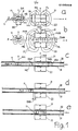
- Fig 2a zeigt eine Ausführungsform des Spiels mit mechanischer Kopplung der Antriebs-Dauermagnete in einem Schnitt A-A von Fig 2b und
- Fig 2b dieselbe Ausführungsform imGrundriss.
- Fig 2c zeigt einen Teil der gleichen Ausführungsform in abmontiertem Zustand in einem Schnitt D-E-F-G von Fig 2d und
- Fig 2d dieselbe Ausführungsform in einer Ansicht C-C von Fig 2c.
- Fig 2e zeigt einen Schnitt B-B der Ausführungsform von Fig 2b
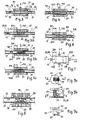
- Fig 3 zeigen Teilausschnitte des Spiels in vereinfachter Darbis 8 stellung, und zwar
- Fig 3 den aus den Antriebs-Dauermagneten bestehenden Antriebsteil des Spiels mit magnetischer Kopplung von zwei Antriebsmagneten in Seitenansicht.
- Fig 4 zeigt denAntriebsteil einer weiteren Ausführungsform des Spiels mit magnetischer Kopplung von drei Antriebsmagneten in Seitenansicht, und
- Fig 5 eine ähnliche Ausführungsform wie Fig 4, und zwar die Fig 5a, Fig 5b, Fig 5c bei je verschiedenen Relativlagen des Figur-Dauermagneten.
- Fig 6 zeigt eine weitere Ausführungsform in Seitenansicht und
- Fig 7 die gleiche Ausführungsform im Grundriss und
- Fig 8 den Antriebsteil einer weiteren Ausführungsform des Spiels in Seitenansicht.
- Fig 9 zeigt einen Bestandteil für eine Spiel-Variante, und zwar Fig 9a in einer Seitenansicht, Fig 9b in einem Schnitt A-A der Fig 9c und Fig 9c einen Schnitt B-B der Fig 9b.
- Fig. 1 shows in principle the action of two permanent magnets of a drive part of the game on the permanent magnet of a game figure, in different figures in Figures la to le.
- Fig. 2a shows an embodiment of the game with mechanical coupling of the drive permanent magnets in a section AA of Fig. 2b and
- Figure 2b shows the same embodiment in plan.
- FIG. 2c shows a part of the same embodiment in the disassembled state in a section DEFG from FIG. 2d and
- Fig. 2d the same embodiment in a view CC of Fig. 2c.
- Fig. 2e shows a section BB of the embodiment of Fig. 2b
- Fig. 3 show partial sections of the game in a simplified position 8 , namely
- 3 shows the side view of the drive part of the game consisting of the drive permanent magnets with magnetic coupling of two drive magnets.
- Fig. 4 shows the drive part of a further embodiment of the game with magnetic coupling of three drive magnets in side view, and
- 5 shows a similar embodiment to FIG. 4, namely FIGS. 5a, 5b, 5c with different relative positions of the permanent magnet.
- 6 shows a further embodiment in side view and
- Fig. 7 shows the same embodiment in plan and
- 8 shows the drive part of a further embodiment of the game in a side view.
- FIG. 9 shows a component for a game variant, namely FIG. 9a in a side view, FIG. 9b in a section AA of FIG. 9c and FIG. 9c a section BB in FIG. 9b.
In den Fig 10 und 11 ist eine Ausführungsform des Antriebsteils des Spiels dargestellt, und zwar zeigen
- Fig 10 einen Längsschnitt F-F der Fig 11
- Fig 11 einen Grundriss
- Fig 12 zeigt die Magnetwirkung eines einzelnen Antriebs-Dauermagneten auf einen Figur-Dauermagneten.
- Fig 13 bis 15 zeigen ausschnittweise drei Ausführungsformen des Spiels im Querschnitt durch die Spielfeldplatten, welche auf der prinzipiellen Wirkungsweise der Fig 12 beruhen, und zwar
- Fig 13 eine Ausführungsform mit nur einem oberen Antriebs-Dauermagneten
- Fig 14 eine Ausführungsform mit einem oberen und einem mittleren Antriebs-Dauermagneten
- Fig 15 eine Ausführungsform mit oberem und mittlerem Antriebs-Dauermagneten, welche derjenigen der Fig 16 bis 18, bei weggelassenem unteren Antriebs-Dauermagneten, entspricht.
- Fig 16 zeigt eine weitere Ausführungsform des Antriebsteils in einem Längsschnit A-A von Fig 17
- Fig 17 zeigt die gleiche Ausführungsform in einer Ansicht B-B von Fig 16 und
- Fig 18 die gleiche Ausführungsform in einem Schnitt C-C oder D-D von Fig 16
- Fig 19 zeigt eine weitere Ausführungsform des Antriebsteils des Spiels im Längsschnitt
- Fig 20 zeigt den Ausschnitt aus einem Antriebsteil einer weiteren Ausführungsform des Spiels
- Fig 21 zeigt eine Spielfigur im Grundriss und
- Fig 22 dieselbe Spielfigur im Längsschnitt A-A von Fig 21
- Fig 23a zeigt eine weitere Spielfigur im Grundriss und
- Fig 23b dieselbe Spielfigur im Längsschnitt von Fig 23a
- Fig 24 zeigt in perspektivischer Darstellung eine weitere Spielfigur
- Fig 25a zeigt eine weitere Spielfigur in Seitenansicht und
- Fig 25b im Grundriss
- Fig 26a zeigt eine weitere Spielfigur im Grundriss und
- Fig 26b in Seitenansicht
- Fig 27a zeigen eine weitere Ausführungsform des Spiels, und zwar bis Fig 27d
- Fig 27a im Grundriss
- Fig 27b in einem Schnitt A-A von Fig 27a
- Fig 27c in einem Schnitt C-C von Fig 27a und
- Fig 27d in einem Schnitt B-B von Fig 27a
- Fig 28 zeigt einen Schnitt C-C der Fig 27a mit Antriebs- Dauermagneten und Spielfigur
- Fig 29 zeigen zwei Spiel-Einsätze in perspektivischer Darstellung und 30
- Fig 31 zeigen Ausschnitte aus einer Ausführungsform des Spiels, und 32 und zwar Fig 31 im Querschnitt und Fig 32 im Grundriss
- Fig 33 zeigt einen Teil des Querschnittes A-A der Fig 27a in vergrösserter Darstellung
- 10 shows a longitudinal section FF of FIG. 11
- 11 shows a floor plan
- FIG. 12 shows the magnetic effect of a single permanent drive magnet on a permanent magnet.
- FIGS. 13 to 15 show sections of three embodiments of the game in cross section through the playing field plates, which are based on the principle of operation of FIG. 12, namely
- 13 shows an embodiment with only one upper drive permanent magnet
- 14 shows an embodiment with an upper and a middle drive permanent magnet
- 15 shows an embodiment with an upper and middle drive permanent magnet, which corresponds to that of FIGS. 16 to 18 with the lower drive permanent magnet omitted.
- FIG. 16 shows a further embodiment of the drive part in a longitudinal section AA from FIG. 17
- Fig. 17 shows the same embodiment in a view BB of Fig. 16 and
- 18 shows the same embodiment in a section CC or DD of FIG. 16
- 19 shows a further embodiment of the drive part of the game in longitudinal section
- 20 shows the detail from a drive part of a further embodiment of the game
- Fig. 21 shows a game figure in plan and
- 22 shows the same game figure in longitudinal section AA from FIG. 21
- 23a shows a further game figure in the plan and
- Fig. 23b the same game figure in longitudinal section of Fig. 23a
- Fig. 24 shows a perspective view of another character
- 25a shows a further game figure in side view and
- Fig. 25b in the floor plan
- 26a shows a further game figure in the plan and
- Fig. 26b in side view
- 27a show a further embodiment of the game, up to FIG. 27d
- Fig. 27a in the floor plan
- Fig. 27b in a section AA of Fig. 27a
- Fig. 27c in a section CC of Fig. 27a and
- 27d in a section BB from FIG. 27a
- Fig. 28 shows a section CC of Fig. 27a with drive permanent magnet and game figure
- 29 show two game inserts in perspective and 30
- Fig 31 show parts of an embodiment of the game, and 32 namely F ig 31 in cross-section and Figure 32 in plan view
- FIG. 33 shows part of the cross section AA of FIG. 27a in an enlarged view
Die prinzipielle Wirkungsweise der Erfindung wird vorerst anhand der Fig la bis le erläutert. In Fig la ist ein mit Figur-Dauermagnet 11 bezeichneter Magnet gezeichnet, welcher in Richtung der Magnetisierungsachse MA, senkrecht zur Unterlage U magnetisiert ist. Der Dauermagnet kann zylinderförmig sein mit Durchmesser DD und Höhe HD. Die Magnet-Feldlinien FL sind schematisiert eingezeichnet, und die Nord-und Südpole des Dauermagneten mit N und S angeschrieben. In Fig la sind zwei weitere mit Antriebs-Dauermagnete 21 und 22 bezeichnete Magnete aufgezeichnet. Diese beiden Magnete können ebenfalls zylinderförmig, mit Zylinder-Durchmesser DDA, sein und je eine Zylinderhöhe HA aufweisen. Sie liegen koaxial ohne Zwischenraum übereinander, sind beide gleichsinnig in Richtung der Magnetisierungsachse MA magnetisiert, wobei diese Magnetisierungsachse parallel verläuft zu denjenigen des Figur-Dauermagneten 11. Auch hier sind die Magnet-Feldlinien FL schematisch eingezeichnet, und es ist klar, dass die magnetische Wirkung der beiden Magnete 21,22 nach aussen gleich ist wie für einen einzigen Dauermagneten mit der doppelten Höhe, also 2 HA. Auch hier sind die Nord- und Südpole der beiden Magnete mit N und S angeschrieben. Die Berührungsfläche der beiden Antriebs- dauermagnete 21, 22 liegt in der Mittelebene ME des Figur-Dauermagneten 11. Bezüglich der X-Koordinate wird der Figur-Dauermagnet in Richtung der eingezeichneten Kraft P von den Antriebs-Dauermagneten abgestossen, und er bewegt sich, auf der Unterlage U gleitend, in dieser Richtung. Ein Umkippen des Figur-Dauermagneten wird dadurch verhindert, dass dessen Durchmesser DD grösser als dessen Höhe HD ist.The principle of operation of the invention is initially explained with reference to FIGS. In Fig la a magnet designated with
In Fig lb sind die gleichen Dauermagnete wie in Fig 1a aufgezeichnet, wobei jedoch die beiden Antriebs-Dauermagnete 21, 22 in Richtung der Magnetisierungsachse MA, und symmetrisch zur Mittelebene ME um eine Distanz DAM voneinander distanziert sind, welche etwas grösser als die Höhe HD des Figur-Dauermagnetes 11 ist. Auch hier ist der Verlauf der Feldlinien FL eingezeichnet, und es ist ersichtlich, dass dieser Verlauf in grösserer Entfernung, also etwa beim Figuren-Dauermagneten, etwa derselbe ist wie bei Fig la. Auch hier wird. deshalb der Figur-Dauermagnet 11 in Richtung P abgestossen. Wandert man in Richtung der Koordinate X vom Figur-Dauermagneten 11 auf der Mittelebene ME nach rechts, so verlaufen die Feldlinien FL zuerst von oben nach unten. An einer kritischen Stelle, welche mit Feldlinie FKR strichpunktiert eingezeichnet ist, erfolgt der Richtungswechsel, und Im Bereich der übereinanderliegenden Antriebs-Dauermagnete 21, 22 verlaufen die Feldlinien von unten nach oben, während sie noch weiter rechts, in grösserer Entfernung, wieder von oben nach unten verlaufen. Dieser Verlauf der Feldlinien hat zur Folge, dass ein längs der Mittelebene beweglicher Figur-Dauermagnet 11 in grösserer Entfernung, also etwa ausserhalb der Feldlinie FKR abgestossen, und in kleiner Entfernung, also etwa innerhalb der Feldlinie FKR von den Antriebs-Dauermagneten 21, 22 angezogen wird.The same permanent magnets as in FIG. 1a are recorded in FIG. 1b, but the two drive
Gemäss Fig 1b ist für den Figuren-Dauermagneten 11 keine Führung vorhanden, und er würde umgekippt und von einem der beiden Antriebs-Dauermagnete 21, 22 angezogen. Um dies zu verhindern, sind gemäss Fig lc die beiden zueinander und zur Mittelebene ME parallel verlaufenden Spielfeldplatten 31 und 32 vorhanden, zwischen welchen der Figuren-Dauermagnet 11 längs der Mittelebene ME lose beweglich ist. Da die Distanz DSP der Spielfeldplatten nur wenig grösser als die Höhe HD des Figuren-Dauermagneten ist, wird dessen Umkippen verhindert.According to FIG. 1b, there is no guide for the
Der Figur-Dauermagnet kann sich, bei stets gleichgerichteter Magnetisierungsachse MA, nur zwischen den Spielfeldplatten längs der Mittelebene ME bewegen. Diese Mittelebene wird im folgenden mit Spielfeldebener bezeichnet. Die Distanz DAM zwischen den Antriebs-Dauermagneten 21 und 22 ist normalerweise etwas grösser als die Distanz DSA von der Oberseite der oberen zur Unterseite der unteren Spielfeldplatte.With permanent magnetization axis MA, the figure permanent magnet can only move between the playing field plates along the central plane ME. This middle level is referred to below as the playing field level. The distance DAM between the drive
In den 3 Figuren lc, ld, 1e ist der Figur-Dauermagnet 11 in drei verschiedenen Relativ-Positionen zu den Antriebs-Dauermagneten 21,22 eingezeichnet. In der Position der Fig 1c wird der Figur-Dauermagnet 11 in Richtung der Kraft PAB abgestossen, in der Position der Fig ld beim kritischen Abstand DKR wird er weder abgestossen noch angezogen, und in der Position von Fig le, bei welcher der kritische Abstand DKR unterschritten ist, wird der Figur-Dauermagnet 11 in Richtung der Kraft PAN angezogen und wird alsdann zwischen den beiden Antriebs- Dauermagneten 21, 22 festgehalten.In the 3 figures 1c, 1d, 1e the figure
Bewegt man die beiden Antriebs-Dauermagnete 21, 22 in der Anordnung der Fig 1c bis le von Hand längs den Spielfeldplatten bzw. längs des ebenen Spielfeldes, so werden die im Spielfeld entfernter liegenden Figur-Dauermagnete stets abgestossen, und.nur nahe gelegene angezogen. Auf diesem Prinzip beruht das Katz- und Maus-Spiel der Ausführungsform der Fig 2a bis welches nun erläutert werden soll. Im Spielfeld 1 zwischen der oberen Spielfeldplatte 32 und der unteren Spielfeldplatte 31 ist in Form der Nachbildung einer Maus eine Spielfigur 12 eingezeichnet, welche einen Figur-Dauermagneten 11 mit der Magnetisierungsrichtung MA, senkrecht zur Ebene des Spielfeldes, enthält. Die Spielfigur kann aus Kunststoff, und der Dauermagnet eingegossen sein. Der Dauermagnet ist bezüglich der normalen Laufrichtung der Spielfigur im vorderen Teil, also gemäss Fig 2aund 2 bin der Nähe des Kopfes der Maus untergebracht, wodurch sich durch Wirkung der abstossenden Kraft durch die Antriebs- Dauermagnete sowie durch die Reibungskraft des Hinterteils der Spielfigur auf der unteren Spielfeldplatte die-Spielfigur in ihrer normalen Laufrichtung von den Antriebs-Dauermagneten entfernt. Die Höhe der Spielfigur ist etwas kleiner als die Distanz DSP der beiden Spielfeldplatten.If the two drive
Die obere Spielfeldplatte 32 besteht aus lichtdurchlässigem Material, z.B. aus Acrylglas. Der obere Antriebs-Dauermagnet 21 liegt unmittelbar über der oberen Spielfeldplatte 32 und der untere Antriebs-Dauermagnet 22 unter der unteren Spielfeldplatte, und zwar koaxial zueinander mit gleicher Magnetisierungsachse MA, deren Magnetisierungsrichtung auch mit dem Figur-Dauermagneten 11 übereinstimmt. Die beiden Antriebs-Dauermagnete 21, 22 sind über eine Antriebsgabel mit den Gabelschenkeln 23 und 24 miteinander starr verbunden, wobei der obere Magnet am Ende des oberen Gabelschenkels 23 und der untere Magnet am Ende des unteren Gabelschenkels 24 fixiert ist und die Verbindungsstelle 28 der beiden Gabelschenkel ausserhalb des Spielfeldes liegt. Die Antriebs-Dauermagnete und die Antriebsgabel mit den Gabelschenkeln bilden zusammen den Antriebsteil, welcher mittels Handgriff 25 von Hand parallel zur Spielfeldebene bewegt werden kann. Die Verbindungsstelle 28 der Gabelschenkel 23 und 24 besteht aus den am unteren Gabelschenkel 24 angebrachten Ansätzen 241 und 242, an welch letzterem der obere Gabelschenkel 23 ansteckbar und mittels der Mitnahmebolzen 244 mitnehmbar ist.The
Der obere Gabelschenkel 23 besteht vorzugsweise aus transparentem Kunststoff und wird durch ein in ihm enthaltenes ferromagnetisches Plättchen 231 durch den im Ansatz 242 enthaltenen Permanent-Magneten 243 im Betriebszustand festgehalten. Am unteren Gabelschenkel 24 ist eine runde Lagerscheibe 245 angebracht, welche in einer Führungsschiene 41 drehbar und achsial schiebbar gelagert ist. An der Führungsschiene sind die Stege 43 mit den Bolzen 42 angebracht, mittels welcher die Führungsschiene an den Spielfeldkörper 312 ansteckbar ist, durch Einstecken in die darin enthaltenen Stecklöcher 315.The
Die mittels der Gabelschenkel 23 und 24 miteinander mechanisch gekoppelten und stets koaxial zueinander liegenden Antriebs-Dauermagnete 21 und 22 lassen sich von Hand mittels des Handgriffs 25 parallel zur Spielfeldebene 1 über das ganze, kreisrunde Spielfeld bewegen, wobei die Bewegung durch Anschlag der Antriebsdauermagnete an den an der oberen und der unteren Spielfeldplatte 31, 32 angebrachten kreisrunden Anschlagrippen 321 und 311 limitiert wird. Die untere Spielfeldplatte 31 ist integriert in den Spielfeldkörper 312, welcher im Blick auf die Spielfeldebene 1 etwa quadratische Form aufweist und in den vier Ecken mit Bodenstützen 314 gegen den Boden abgestützt ist. Im Spielfeldkörper 21 ist auch die kreisrunde Spielfeldgrenze 101 enthalten, wodurch die zwischen den Spielfeldplatten befindlichen Spielfiguren 12 nur im durch die Spielfeldgrenze gegebenen kreisrunden Bereich des Spielfeldes bewegbar sind. Die obere Spielfeldplatte 32 hat im Blick auf die Spielfeldebene angenähert quadratische Form, wobei das eigentliche Spielfeld die im Quadrat eingeschlossene Kreisfläche mit Spielfeldbegrenzung 101 als Umfangslinie umfasst. Die obere Spielfeldplatte ist in den Spielfeldkörper 3l21ose einlegbar und wird durch einen Auflage-Absatz 102 auf Spielplattendistanz DSP gehalten und durch Randleisten 313 des Spielfeldkörpers 312 zentriert.The drive
In Fig 2a und 2b ist die Antriebsgabel mit den Gabelschenkeln 23 und 24 sowie die Führungsschiene auf der linken Seite des Spielfeldkörpers 312 angesteckt gezeichnet. In die Stecklöcher 315 auf der rechten Seite des Spielfeldkörpers könnte eine zweite Führungsschiene 41 mit Antriebsgabel angesteckt werden für einen zweiten Spieler.In FIGS. 2a and 2b the drive fork with the
In Fig 2c und 2d ist diese zweite Antriebsgabel mit Führungsschiene 41 im vom Spielfeldkörper abmontiertem Zustand gezeichnet, wobei in Fig 2c der obere Gabelschenkel vom unteren abgetrennt gezeichnet ist.2c and 2d, this second drive fork with
Die leichte Montier- und Demontierbarkeit von oberem Gabelschenkel und oberer Spielfeldplatte ist vorteilhaft für das leichte Auswechseln von Spielfiguren sowie das Einsetzen von Spielfeldeinsätzen 80 oder 90 gemäss Fig 29 oder Fig 30.The ease of assembly and disassembly of the upper fork leg and the top playing field plate is advantageous for the easy replacement of playing figures and the insertion of playing field inserts 80 or 90 according to FIG. 29 or FIG. 30.
Die von Hand mittels Handgriff 25 bewegbaren Antriebs-Dauermagnete 21, 22 können im Falle des Katz- und Maus-Spiels die Rolle der Katze übernehmen und auch mit einem Katzenbild versehen sein, während die Spielfigur 12 die Maus darstellt. Natürlich könnte gleichzeitig eine grössere Anzahl von Spielfiguren bzw. Mäusen im Spielfeld 1 vorhanden sein. Wird der, die Rolle der Katze spielende Antriebsteil bewegt, so haben die als Mäuse dargestellten Spielfiguren, zufolge der abstossenden Wirkung der Dauermagnete, stets die Tendenz, vor der Katze zu fliehen. Nur wenn es gelingt, mit dem Antriebsteil 20 genügend nahe, d.h. in einem Abstand unter die kritische Distanz an eine Spielfigur zu gelangen, wird diese zwischen den Antriebs-Dauermagneten festgehalten bzw. von der Katze gefangen. Das Spiel mit den Dauermagneten kann somit ein Geschicklichkeitsspiel sein, bei dem die Katze in möglichst kurzer Zeit möglichst viele Mäuse fangen soll.The drive
Bei dieser Ausführungsform des Spiels mit nur einem oberen und einem unteren Antriebsdauermagneten ist das Einfangen der Spielfiguren etwas zu leicht möglich. Bei der Ausführungsform gemäss Fig 16 bis 23 ist dieser Mangel behoben.In this embodiment of the game with only one upper and one lower permanent magnet, it is somewhat too easy to capture the game characters. In the embodiment according to FIGS. 16 to 23, this defect has been eliminated.
Ein gewisser weiterer Nachteil der Ausführungsform des Spiels gemäss Fig 2a bis 2e liegt darin, dass für die mechanische Kopplung der beiden Antriebs-Dauermagnete eine relativ aufwendige Mechanik mit Antriebs- gabel und Führungsschiene erforderlich ist. Weiter ist nachteilig, dass die Grösse des Spielfeldes durch diese Mechanik limitiert ist. Diese Nachteile sind in den nachfolgend beschriebenen Ausführungsformen dadurch vermieden, dass die Antriebs-Dauermagnete nicht mechanisch, sondern magnetisch miteinander gekoppelt sind. Die prinzipielle Wirkungsweise wird anhand der Fig 3 beschrieben. Ueber der oberen Spielfeldplatte 32 befindet sich der obere Antriebs-Dauermagnet 21, welcher z.B. ein Zylinder mit Zylinderachse MA und Höhe HA sein kann. Die an ihm angebrachten Laufrollen 98 verringern die Reibung beim Bewegen des Magneten über die Spielfeldplatte. Am oberen Magneten ist ein Handgriff 25 für die Betätigung von Hand angebracht. Unter der unteren Spielfeldplatte 31 ist der untere Antriebs-Dauermagnet 22 angebracht mit gleicher Form und gleichgerichteter Magnetisierungsachse MA wie der obere Magnet und wie der Figur-Dauermagnet 11. Die beiden Antriebs-Dauermagnete ziehen sich an, und beim Bewegen des oberen Antirebs-Dauermagneten 21 von Hand mittels Handgriff 25 über die obere Spielfeldplatte wird der untere Antriebs-Dauermagnet 22 durch magnetische Kopplung mitgenommen, und die Magnetisierungsachsen MA bleiben im Wesentlichen koaxial, und die Wirkung der beiden Antriebs- Dauermagnete auf den Figur-Dauermagneten 11 ist die gleiche wie bei der oben anhand von Fig 2a bis 2e beschriebenen mechanischen Kopplung der Magnete. Die an beiden Dauermagneten angebrachten Laufrollen 98 gestatten Bewegungen längs der Spielfeldplatten in einer Koordinatenrichtung mit geringer Reibung. Es werden unten Ausführungsformen beschrieben, welche reibungsarme Bewegungen in allen Richtungen der Spielfeld-Ebene 1 gestatten. Die Dauermagnete sind in Fig 3 und den nachfolgenden Figuren zur Kenntlichmachung senkrecht schraffiert. Durch die magnetische Anziehungskraft der beiden Antriebs-Dauermagnete werden die beiden Spielfeldplatten 31, 32 aufeinander zu verbogen, und es besteht die Möglichkeit, dass die Spielfiguren mit den Figur-Dauermagneten 11 zwischen den Platten eingeklemmt werden. Bei dieser Ausführungsform müssten die Spielfeldplatten genügend dick oder das Spielfeld genügend klein sein. Zur Vermeidung dieses Nachteils kann ein dritter, der mittlere Antriebs-Dauermagnet 235 hinzugefügt werden, welcher zwischen den beiden Spielfeldplatten plaziert ist und diese gegeneinander abstützt. Der mittlere Antriebs-Dauermagnet hat aber noch weitere, unten beschriebene Funktionen. Die prinzipielle Anordnung ist aus Fig 4 ersichtlich.A certain further disadvantage of the embodiment of the game according to FIGS. 2a to 2e lies in the fact that a relatively complex mechanism with a drive fork and guide rail is required for the mechanical coupling of the two drive permanent magnets. Another disadvantage is that the size of the field is limited by this mechanism. In the embodiments described below, these disadvantages are avoided in that the drive permanent magnets are coupled to one another magnetically rather than mechanically. The basic mode of operation is described with reference to FIG. 3. Above the upper
Alle drei Antriebs-Dauermagnete 21, 22, 235 haben gleichgerichtete Magnetisierungsachsen MA, sind durch magnetische Kupplung verbunden und haben in Richtung der Spielfeldebene 1 gleiche Abmessungen und können zur Reibungsverminderung auch mit hier nicht gezeichneten Laufrollen 98 versehen sein.All three drive
Eine solche Anordnung gemäss Fig 4 hat auf eine Spielfigur bzw. den Figur-Dauermagneten/uie gleiche Wirkung, wie sie anhand der Fig la beschrieben wurde, d.h. die Spielfigur wird immer abgestossen und niemals, auch nicht bei kleinen Distanzen, angezogen.Such an arrangement according to FIG. 4 has the same effect on a game figure or the figure permanent magnet / uie as was described with reference to FIG. the character is always repelled and never attracted, not even at short distances.
Um auch unter Verwendung eines zwischen den Spielfeldplatten liegenden mittleren Antriebs-Dauermagneten 235 die Wirkung zu erhalten, dass die Spielfiguren bei grossen Distanzen abgestossen und bei kleinen Distanzen angezogen werden, wird eine Ausführungsform gewählt, welche gemäss der Fig 5a bis 5c beschrieben wird.In order to obtain the effect, even with the use of a central drive
Bei dieser Variante hat der mittlere Antriebs-Dauemagnet 235 in Richtung der Ebene des Spielfeldes 1 zumindest auf einer Seite eine um ein Differenzmass DM geringere Abmessung als die unteren und oberen Antriebs-Dauermagnete 21, 22. Ein auf dieser Seite befindTicher Figur-Dauermagnet 11 wird gemäss Fig 5a von den Antriebs-Dauermagneten abgestossen, wenn er von diesen einen grösseren als den kritischen Abstand DKR aufweist, was durch den am Figur-Dauermagneten 11 eingezeichneten Pfeil PAB angedeutet ist. Weist der Figur-Dauermagnet 11 gemäss Fig 5b den kritischen Abstand DKR auf, wird er weder abgestossen noch angezogen. Weist der Figur-Dauermagnet 11 gemäss Fig 5c einen kleineren als den kritischen Abstand DKR von den Antriebs-Dauermagneten auf, so wird er von diesen angezogen bzw. eingefangen, was durch den Pfeil PAN markiert ist. Die Grösse der kritischen Distanz DKR ist abhängig von der Grösse des Differenzmasses DM. Bei grossem Differenzmass DM wird auch DKR gross, und das Anziehen bzw. Einfangen der Spielfiguren wird erleichtert. Wäre das Differenzmass DM so gross, dass der mittlere Antriebs-Dauermagnet verschwindet, so wäre der anhand der Fig lc bis le beschriebene Fall vorhanden. Bei kleinem Differenzmass DM wird DKR ebenfalls klein, und das Anziehen bzw. Einfangen der Spielfiguren wird erschwert. Für DM+Null tritt nur noch Abstossung des Spiel-Dauermagneten auf, wie bei Fig 4 gezeigt wurde.In this variant, the central drive
Bei der Ausführungsform gemäss der Fig 6 und Fig 7 ist in Richtung der Ebene des Spielfeldes 1 in einer von vier orthogonalen, mit +X, -X, +Y, -Y bezeichneten, Koordinatenrichtungen, nämlich in der mit -X als Vorderseite bezeichneten Koordinatenrichtung der mittlere Antriebs-Dauermagnet (235) um ein Differenzmass DM gegenüber den oberen und unteren Antriebs-Dauermagneten zurückstehend. An dieser Vorderseite -X wird ein Figur-Dauermagnet 11 bei grösserer Distanz abgestossen und bei kleiner Distanz angezogen bzw. eingefangen. An der der Vorderseite gegenüberliegenden, mit +X bezeichneten, Hinterseite ist am mittleren Antriebs-Dauermagneten 235 ein nichtmagnetischer Ansatz 216 befestigt, welcher in Richtung +X um eine Distanz DH herausragt. Dieser Ansatz 216 bewirkt, dass von der Hinterseite +X eine Spielfigur 12 bzw. ein Figur-Dauermagnet 11 stets mehr als die kritische Distanz von den Antriebsmagneten entfernt ist, so dass er nur abgestossen werden kann. Quer zur Längsachse X, also in der mit +Y bezeichneten rechten Seite und der mit -Y bezeichneten linken Seite, ist der mittlere Antriebs-Dauermagnet 235 in Richtung senkrecht zu den Spielplatten gesehen etwa bündig mit den oberen und unteren Antriebs-Dauermagneten 21 und 22, und an diesen Seiten ist nur Abstossung der Figur-Dauermagnete 11 möglich, wie anhand von Fig 4 beschrieben wurde.In the embodiment according to FIGS. 6 and 7, the direction of the plane of the
Bei der Ausführungsform gemäss Fig 6 und 7 ist somit ein Anziehen bzw. Einfangen von Spielfiguren bzw. Figur-Dauermagneten 11 nur von einer Seite, der Vorderseite -X her möglich.In the embodiment according to FIGS. 6 and 7, a tightening or catching of game figures or figure
Nichtmagnetische Ansätze 216 könnten auch an den andern Seiten des Dauermagneten 235 angebracht sein. Bei den vereinfachten Darstellungen der Fig 4 bis 7 sind Laufrollen 98 weggelassen, welche in Fig 8 eingezeichnet sind. Fig 8 zeigt eine Ausführungsform von Antriebs-Dauermagneten ähnlich wie in Fig 5, mit Laufrollen 98 zur Verminderung der Reibung auf den Spielplatten.
Der mittlere Antriebsmagnet 235 ist gegen die untere und die obere Spielplatte mit Laufrollen 98 abgestützt.The
Die Ausführungsform gemäss Fig 8 mit den Laufrollen 98 gestattet reibungslose Bewegung nur in einer, in Fig 8 mit t X bezeichneten Richtung. Zur Ermöglichung der reibungslosen Bewegung in allen Richtungen der Ebene des Spielfeldes werden die Antriebs-Dauermagnete anstatt über Laufrollen, über die Schwenkrollen 50 auf die Spielfeldplatten abgestützt. Solche Schwenkrollen sind bekannt und werden beispielsweise bei fahrbaren Serviertischen verwendet. Die Wirkungsweise ist aus den Fig 9a bis 9c ersichtlich. Aufder zum Spielfeld senkrecht stehenden Schwenkachse 52 ist der Schwenkkörper 53 drehbar gelagert.The embodiment according to FIG. 8 with the
Im Schwenkkörper ist eine auf einer Spielfeldplatte laufende Laufrolle 55 in einer Rollenachse 54 drehbar gelagert, welche Achse parallel zur Spielfeldebene verläuft und von der Schwenkachse 52 distanziert ist. Die Schwenkachse 52 ist verbunden mit dem Flansch 51, welcher seinerseits mittelbar oder unmittelbar an einem Antriebs-Dauermagneten befestigt ist. Die Lager könnten auch als Kugellager ausgebildet sein.In the swivel body, a running roller 55 running on a playing field plate is rotatably mounted in a
Die Ausführungsform des Spiels gemäss der Fig 10 und 11 entspricht prinzipiell derjenigen der Fig 6 und 7, wobei aber hier an den Antriebs-Dauermagneten Schwenkrollen 50 mittelbar über Kunststoff-Teile befestigt sind. Der obere Antriebs-Dauermagnet 21 ist in einen Kunststoffteil 211 eingebettet, in welchem vier Schwenkrollen 50 fixiert sind, welche den Magneten 21 von der oberen Spielfeldplatte 32 distanzieren. Der obere Antriebs-Dauermagnet 21 ist mittels Handgriff 25 von Hand bewegbar. Der untere Antriebs-Dauermagnet 22 ist gleich aufgebaut, mit vier auf der unteren Spielfeldplatte laufenden, im Kunststoffteil 261 fixierten Schwenkrollen, jedoch ohne Handgriff. Der mittlere Antriebs-Dauermagnet 235 ist in einen als Kunststoffkörper ausgebildeten Ansatz 216 eingebettet, in welchem vier auf der unteren Spielfeldplatte 31 und zwei auf der oberen Spielfeldplatte laufende Schwenkrollen 50 fixiert sind. In den Kunststoffansatz 216 ist auch der Mittelteil 217 und der Hinterteil 218 integriert, dessen Funktion anhand der Fig 6 und 7 erläutert wurde. Die drei Antriebs-Dauermagnete haben, in Richtung auf die Spielfeldplattenebene gesehen, Rechteckform. Wie anhand von Fig 7 erläutert wurde, können Spielfiguren 12 nur von der mit -X bezeichneten Vorderseite eingefangen werden. Diese Vorderseite ist in Fig 11 auf dem Kunststoffteil 211 mit einem Katzenkopf 262 bemalt.The embodiment of the game according to FIGS. 10 and 11 corresponds in principle to that of FIGS. 6 and 7, but here swivel
In den Fig 10 und 11 ist der Zustand gezeichnet, bei dem an der Vorderseite eine als Maus dargestellte Spielfigur 12 mit dem Figur-Dauermagneten 11 eingefangen wurde.FIGS. 10 and 11 show the state in which a game figure 12 represented as a mouse with the
Das Ausstossen der eingefangenen Maus erfolgt nach einer ersten Methode so, dass mit den Antriebs-Dauermagneten 21, 22, 23 mit der Rückseite der Maus voran an die Randleisten 311, 321 bei einem geöffneten Spielfeld-Ausgang 91 gefahren wird. Alsdann wird mit einem hakenförmigen Betätigungsmittel 61 durch einen Schlitz 322 in der oberen Spielfeldplatte der mittlere Antriebs-Dauermagnet 235 im Spielfeld radial nach aussen, also in Fig 10 oder 11 nach links gedrückt, wodurch die linke Kante bzw. die Vorderseite des mittleren Antriebs-Dauermagneten 235, senkrecht zur Spielfeldebene gesehen, bündig wird mit den linken Kanten der oberen und unteren Antriebs- Dauermagnete und die Spielfigur vehement aus dem Spielfeldausgang 91 ausgestossen wird.The captured mouse is ejected according to a first method in such a way that the drive
Die Antriebs-Dauermagnete 21, 22, 235 könnten auch aus je zwei, statt nur je einem, Teilen bestehen, welche durch je einen Kunststoffkörper miteinander verbunden sind.The drive
Anhand der Fig la bis le wurde die prinzipielle Wirkungsweise des Spiels unter Verwendung eines oberen und eines unteren Antriebs-Dauermagneten 21, 22 erläutert und gezeigt, dass ein Figur-Dauermagnet 11 bei grössererer Distanz von den Antriebs-Dauermagneten abgestossen und bei Unterschreiten einer kritischen Distanz DKR von diesen angezogen wird. Eine ähnliche Wirkung lässt sich bei richtiger Dimensionierung auch mit einer Anordnung gemäss Fig 12 erzielen, bei welcher nur ein einziger, nämlich der obere Antriebs-Dauermagnet 21 auf den Figur-Dauermagnet 11 einwirkt. Der Verlauf der magnetischen Feldlinien FL des Antriebsmagneten zeigt, dass diese ausserhalb einer kritischen Distanz DKR das Spielfeld 1 von oben nach unten, und innerhalb der kritischen Distanz von unten nach oben durchlaufen. Ein Figur-Dauermagnet 11 wird also auch hier ausserhalb der Distanz DKR vom Antriebs-Dauermagneten abgestossen und innerhalb dieser Distanz angezogen oder eingefangen. Die Wirkung ist allerdings nicht so optimal wie bei der Ausführungsform von Fig la bis le.The principle of operation of the game using an upper and a lower drive
Bei der Ausführungsform gemäss Fig 12 mit nur einem Antriebs-Dauermagneten 21 sollte dieser relativ zum Abstand DSP der beiden Spielfeldplatten grossen Durchmesser DDA aufweisen.In the embodiment according to FIG. 12 with only one drive
In Fig 13 ist als Spielfigur 12 eine Maus eingezeichnet, welche bei grösserer Distanz vom einzigen, oberen Antriebs-Dauermagneten 21 abgestossen und bei kleiner Distanz angezogen oder eingefangen wird.In FIG. 13, a mouse is drawn in as game figure 12, which is repelled at a greater distance from the single, upper drive
In Fig 14 ist zusätzlich zum oberen, auch ein mittlerer Antriebs- Dauermagnet 235 vorhanden, welcher vom oberen Antriebs-Dauermagneten 21 durch magnetische Kopplung mitgeschleppt wird. Die Wirkungsweise auf die Spielfigur 12 ist ähnlich der anhand von Fig 5a bis 5c beschriebenen Ausführungsform.In FIG. 14, in addition to the upper, there is also a medium
In Fig 15 ist eine Ausführungsform der Antriebs-Dauermagnete aufgezeichnet, welche derjenigen der unten, anhand der Fig 16 bis 18 beschriebenen Ausführungsform entspricht, mit der einzigen Ausnahme, dass in Fig 15 der untere Antriebs-Dauermagnet 22 weggelassen ist. Die Wirkungsweise ist ähnlich wie unten anhand von Fig 16 bis 18 beschrieben ist. Bei der Ausführungsform von Fig 15 kann das Ausstossen von eingefangenen Spielfiguren durch blosses Abheben des oberen Antriebs-Dauermagneten 21 von der Spielfeldplatte 32 erfolgen, wonach durch die Abstosswirkung des mittleren Magneten 235 die gefangene Spielfigur 12 abgestossen wird.15 shows an embodiment of the drive permanent magnet which corresponds to that of the embodiment described below with reference to FIGS. 16 to 18, with the only exception that the lower drive
Die Spielarten der Ausführungsformen der Fig 13 bis 15 mit fehlendem unteren Antriebs-Dauermagneten 22 sind praktisch dieselben wie bei den beschriebenen Ausführungsformen mit vorhandenem unteren Spielfeldmagneten.The game types of the embodiments of FIGS. 13 to 15 with a missing lower drive
Für die Ausführungsformen der Fig 13 bis 15 kann das Spielfeld konstruktiv ähnlich wie in Fig 27 dargestellt ausgeführt sein.For the embodiments of FIGS. 13 to 15, the playing field can be designed similarly to that shown in FIG. 27.
Selbstverständlich können die Antriebsmagnete 21, 235 der Fig 13 bis 15 auch mit Schwenkrollen 50 versehen sein.Of course, the
Bei der Ausführungsform von Fig 16 bis 18 haben die Antriebs-Dauermagnete 21, 22 und 235 parallel zur Spielfeldebene ringförmigen Querschnitt mit Innenkreisdurchmesser DI. Beim mittleren Antriebs- Dauermagneten 235 ist zudem ein Segment der Dicke DM weggeschnitten, um das Einfangen von Spielfiguren möglich zu machen, wie oben anhand der Fig 5a bis 5c beschrieben wurde. Im Handgriff 25 kann der obere Gabelschenkel 23 und im Bolzen 222 der untere Gabelschenkel 24 im Falle der mechanischen Kopplung fixiert werden. Die Ausführungsform ist aber auch für rein magnetische Kopplung geeignet, wobei die Gabelschenkel entfallen.In the embodiment of FIGS. 16 to 18, the drive
Der kreisringförmige Querschnitt ist für die Zentrierung und Mitnahme des mittleren 235 und unteren 22 durch den oberen 21 Antriebs-Dauermagneten vorteilhaft,und ausserdem ist der mittlere Antriebs-Dauermagnet 235 relativ zu den beiden anderen um die Ringachse Z verdrehbar, ohne dass hemmende magnetische Kräfte auftreten.The circular cross-section is advantageous for centering and driving the middle 235 and lower 22 through the upper 21 drive permanent magnet, and moreover the middle drive
Der am mittleren Antriebs-Dauermagneten 235 befestigte Ansatz 216 aus Kunststoff weist eine spezielle Form auf, welche das Einfangen von Spielfiguren 12 wohl möglich macht, aber wesentlich erschwert. Der Ansatz 216 weist an der linken mit Fangstelle 250 bezeichneten Seite, bei welcher am mittleren Magneten 235 das Segment mit Tiefe DM fehlt, eine rachenähnliche Oeffnung mit den Rachenteilen 215, einer Rachenweite DE und eine Rachentiefe DW auf.The
Die mittlere Partie 217 des Ansatzes 216 überragt den Durchmesser des Antriebs-Dauermagneten soviel, dass hier eine Anziehung von Spielfiguren nicht möglich ist. Der, der Fangstelle 250 gegenüberliegende, hintere Teil 218 lässt eine Anziehung von Spielfiguren ebenfalls nicht zu. Am Ende des Teils 218 befindet sich der Schwanzteil 219, welcher auf der oberen Spielfeldplatte 32 abgestützt ist. Mittels der am Ansatz 216 befestigten und gegen die untere Spielfeldplatte 31 vorgespannte Blattfeder 214 wird der Schwanzteil 219 gegen die obere Spielfeldplatte gedrückt. An den Berührungspunkten BP des Schwanzteils 219 und der Blattfeder 214 mit den Spielfeldplatten (31, 32) entstehen beim Bewegen der Antriebs-Dauermagnete parallel zur Spielfeldebene 1 hemmende Reibungskräfte, welche bewirken, dass sich die Längsachse LA des Ansatzes 216 stets in die Richtung der Bewegung ausrichtet, wobei die Fangstelle 250 stets vorn, und der Schwanzteil 219 stets hinten liegt.The
Der mittlere Antriebs-Dauermagnet 235 liegt näher beim von Hand bewegten oberen Antriebs-Dauermagneten 21 als beim nur durch magnetische Kopplung mitgeschleppten unteren Antriebs-Dauermagneten 22, was die Mitnahme erleichtert.The middle drive
Die Vergrösserung der Distanz zum unteren Magneten wird durch die Ausbuchtung 213 des Ansatzes 216 gewährleistet.The enlargement of the distance to the lower magnet is ensured by the
Die Wirkungsweise beim Einfangen von Spielfiguren wird unten erläutert.The way in which characters are caught is explained below.
Bei der beschriebenen Ausführungsform gleiten die Antriebs-Dauermagnete 21, 22 unter Ueberwindung von Reibungskräften über die Spielfeldplatten. Zur wesentlichen Verminderung der Reibungskräfte und zur zuverlässigen Mitnahme bei magnetischer Kopplung kann an den Antriebs-Dauermagneten im Innenraum je eine Schwenkrolle 50 gemäss Fig 19 angebracht sein, welche die Magnete gegen die Spielfeldplatten abstützen. Die Schwenklager dieser Schwenkrollen 50 sind vorteilhaft als Kugellager ausgebildet.In the embodiment described, the drive
Eine weitere Variante zur Verminderung der Reibung für den mittleren Antriebs-Dauermagneten 235 ist in Fig 20 gezeigt. Konzentrisch zur Magnet-Mittelachse MA, welche gleichzeitig die magnetische Achse ist, ist eine Bohrung 525 angebracht, in welcher, praktisch spielfrei, zwei Kugeln 524 mit dem Durchmesser der halben Spielfeldplatten-Distanz DSP übereinander angeordnet sind. Flexible Spielfeldplatten 31, 32, welche durch die magnetischen Kräfte der Antriebs-Dauermagnete gegeneinander gedrückt werden, werden so durch die gegenläufigen Kugeln abgestützt und die Reibung beim Bewegen der Antriebs-Dauermagnete wird wesentlich vermindert.A further variant for reducing the friction for the central drive
In den Fig 21 bis 24 sind zwei Spielfiguren 12 aufgezeichnet, welche speziell für die Antriebs-Dauermagnete 21, 22, 235 der Fig 16 bis 20 geeignet sind. Fig 21 und Fig 22 zeigt eine Maus als Spielfigur 12. Das Figur-Gehäuse 121 trägt den Figur-Dauermagneten 11 an der Vorderseite sowie einen weiteren Zusatz-Dauermagneten 11; beide mit gleichgerichteter magnetischer Achse MA. Hinten sind zwei Laufrollen 99 angebracht und im vorderen Teil eine Schwenkrolle 50, wobei die Rollen auf der unteren Spielfeldplatte 31 laufen. Der Zusatz-Dauermagnet 11 hat den Zweck, die abstossende Wirkung zu verstärken.21 to 24 show two
Soll diese Spielfigur mit Antriebsmagneten der Ausführungsform von Fig 16 bis 20 bewegt und eingefangen werden, so ergibt sich folgende Wirkungsweise:
- Beim Bewegen der Antriebs-Dauermagnete gegen die Spielfigur 12 wird diese abgestossen, wobei durch Wirkung der magnetischen Kräfte sowie der Schwenkrolle 50 und der Laufrollen 99 der
Kopf der Spielfigur 12 in Laufrichtung immer vorn und vom Antriebsmagneten abgewendet sein wird. Die rachenähnliche Oeffnung mit Rachenweite DE gemäss Fig 17 wird in Laufrichtung des Antriebsmagneten ebenfalls vorn sein, die fliehende Maus kann aber nicht eingefangen werden, da die Maus auf allen Seiten, mit Ausnahme des Kopfes, eine grössere Abmessung aufweist als der Rachenweite DE entspricht. Nur wenn es gelingt, den Kopf der Maus mit dem Figur-Dauermagneten 11 in den Rachen zu stecken, kann sie gefangen werden.
- When the drive permanent magnets are moved against the game figure 12, the latter is repelled, the head of the game figure 12 in the running direction always being turned away from the drive magnet due to the action of the magnetic forces and the
swivel roller 50 and therollers 99. The throat-like opening with a throat size DE according to FIG. 17 will also be at the front in the direction of travel of the drive magnet, but the fleeing mouse cannot be caught because the mouse has a larger dimension than the throat size DE on all sides, with the exception of the head. It can only be caught if the head of the mouse with thepermanent magnet 11 is stuck in the throat.
Die Spielfigur 12 gemäss der Fig 23a und 23b ist ähnlich aufgebaut, hat aber einen etwas anders geformten Tragkörper 121 und kann eine Geldmünze 93 tragen. Die Spielfigur samt Münze soll eingefangen werden, was auch hier nur von der Vorderseite her, beim Figur-Dauermagneten 11, möglich ist.The game figure 12 according to FIGS. 23a and 23b has a similar structure, but has a slightly differently shaped
Eine Methode des Ausstossens der eingefangenen Spielfiguren wurde anhand von Fig 10 beschrieben, eine weitere Methode ist unten angegeben.One method of ejecting the captured pawns has been described with reference to Fig. 10, another method is given below.
In Fig 24 ist eine Spielfigur 12 als Nachbildung eines Fahrzeuges mit Rädern 99, und in Fig 25a, b eine Spielfigur 12 als Nachbildung eines Schafes aufgezeichnet. Bei beiden Spielfiguren sind die Figur-Dauermagnete 11 in deren normaler Laufrichtung vorn angebracht, wodurch die, durch die Abstosswirkung der Antriebs-Dauermagnete 21, 22 bewirkte,Bewegung der Spielfiguren in deren normaler Laufrichtung erfolgt. Die Figur-Dauermagnete 11 sind vorzugsweise in einen, die Spielfiguren darstellenden Kunststoffteil eingebettet.24 shows a game figure 12 as a replica of a vehicle with
In Fig 26a, b ist eine runde Spielfigur 12 mit in Kunststoff eingebetteten Figur-Dauermagneten 11 aufgezeichnet, welche beispielsweise als Nachbildung eines Fussballs dienen kann.26a, b show a round game figure 12 with figure
Es wird nun die Ausführungsform des Spiels gemäss der Fig 27a bis d beschrieben. Spielfeldplatten 31 und 32 sowie Spielfeldkörper 312 sind ähnlich der Ausführungsform, wie sie anhand der Fig 2a bis e beschrieben wurde, sind aber in Fig 27 etwas vergrössert gezeichnet. Ferner ist hier der Antriebsteil mit Antriebsgabel mit den Gabelschenkeln 23 und 24 und der Führungsschiene 41, welche der mechanischen Kopplung der Antriebs-Dauermagnete 21, 22 dienen, weggelassen. Die Ausführungsform gemäss Fig 27 ist nur für magnetische Kopplung der Antriebsmagnete geeignet, wobei jedoch durch die im Spielfeldkörper 312 enthaltenen Löcher 315 Führungsschienen mit Antriebsgabeln im Bedarfsfall ankoppelbar sind.The embodiment of the game according to FIGS. 27a to d will now be described. Playing
Gegenüber der Ausführungsform von Fig 2 weist diejenige von Fig 27 einige zusätzliche Vorrichtungen auf. Einmal ist in jeder der vier Ecken der etwa quadratischen Grundrissform von Spielfeldkörper 312 und oberer Spielfeldplatte 32 ein verschliessbarer Spielfeldausgang 91 vorhanden, welcher aus dem Spielfeld über die verlängerte untere Spielfeldplatte und deren gekrümmte Rampe 317 nach aussen führt. In Fig 27c ist ein solcher verschliessbarer Spielfeldausgang 91 im Schnitt gezeichnet. In der oberen Spielfeldplatte 32 ist eine auf-und zuklappbare Klappe 325 in den Lagern 329 um die Achse 328 schwenkbar gelagert, wobei der vordere Klappenteil 326 durch einen Schlitz 330 in der oberen Spielfeldplatte etwa senkrecht zur Spielfeldebene in den Spielfeldausgang 91 hineinragt und diesen verschliessen kann. Mittels des Handgriffs 327 kann die Klappe geöffnet werden, und der geöffnete Zustand ist in Fig 27c punktiert eingezeichnet. Im geöffneten Zustand können die Spielfiguren durch den Spielfeldausgang 91 über die Rampe 317 nach aussen gelangen. Die Spielfeldausgänge 91 sind Kanäle, welche direkt an die Spielfeldbegrenzung 101 anschliessen, und der Klappenteil 326 liegt etwa tangential zur Spielfeldbegrenzung, wie aus Fig 27a ersichtlich ist. Beidseits der Spielfeldausgänge 91 und in der Nähe der Spielfeldbegrenzung 101 und etwa auf der Höhe des Spielfeldes sind Randmagnete 70 im Spielfeldkörper 312 eingelagert, deren magnetische Achsen MA gleichgerichtet sind wie diejenige des Antriebsteils und der Spielfiguren. Die Randmagnete haben das Bestreben, die Spielfiguren vom Spielfeldrand weg gegen die Spielfeldmitte abzustossen, sowie bei geöffneter Klappe 25 im Spielfeldausgang 91 befindliche Spielfiguren nach aussen auszustossen.Compared to the embodiment of FIG. 2, that of FIG. 27 has some additional devices. On the one hand, in each of the four corners of the roughly square plan shape of the
Spielfeldkörper 312 mit integrierter unterer Spielfeldplatte 31 sowie obere Spielfeldplatte 32 und Klappen 25 bestehen aus Kunststoff.
Anhand von Fig 10 und 11 wurde eine erste Methode zum Ausstossen von eingefangenen Spielfiguren 12 durch den geöffneten Spielfeldausgang 91 beschrieben.10 and 11, a first method for ejecting captured
Eine zweite Methode wird nun anhand von Fig 28 kurz beschrieben. Eine eingefangene Spielfigur 12 von der Art gemäss Fig 21, 22 oder Fig 23, 24 ist von den Antriebs-Dauermagneten 21, 22, 235 von der Art von Fig 16 bis 19 eingefangen gezeichnet und ist mit ihrer Rückseite in den Spielfeldausgang 91 ragend verbracht worden. Beim Bewegen des oberen Antriebs-Dauermagneten 21 mittels Handgriff 25 nach rechts, also in Richtung Spielfeldmitte, wird der Schwanzteil 219 des mittleren Antriebs-Dauermagneten in die Kerbe 324 gedrückt und an der Bewegung nach rechts verhindert und die Spielfigur 12 wird nach links über die Rampe 317 ausgestossen.A second method will now be briefly described with reference to FIG. 28. A captured game figure 12 of the type according to FIGS. 21, 22 or 23, 24 is drawn in by the drive
In Fig 27a sind die oberen beiden Spielfeldausgänge 91 für das Ausstossen der Spielfiguren nach der ersten Methode mit Schlitzen 322, während die unteren beiden Spielfeldausgänge für das Ausstossen nach der zweiten Methode mit Kerben 324 vorgesehen sind.In FIG. 27a, the top two field exits 91 are provided with
Da der obere Antriebs-Dauermagnet 21 und die obere, nur aufgelegte Spielfeldplatte sehr leicht wegnehmbar sind, können mittlere Antriebs- Dauermagnete 235, Spielfiguren 12 und auch Spieleinsätze 85 leicht ins Spielfeld eingesetzt oder wieder herausgenommen werden.Since the upper
Die Spieleinsätze 85, beispielsweise gemäss der Fig 29 oder Fig 30, können bei abgehobener oberer Spielfeldplatte 32 auf die untere 31 eingelegt werden. Sie bestehen beispielsweise aus kreisrunden Folien oder Papieren 80 oder 90 mit Durchmesser kleiner als der Durchmesser der Spielfeldbegrenzung 101. Auf den Folien können Objekte, wie Fussballtore 81 oder Slalomstangen 91, aufgebracht sein, deren Höhe aber die Spielfelddistanz DSP nicht überschreiten darf. Auf den Folien 80 oder 90 können auch Zeichnungen 82 oder 92 angebracht sein.The game inserts 85, for example according to FIG. 29 or FIG. 30, can be placed on the lower 31 when the upper
Mit dem Spieleinsatz 85 gemäss Fig 29 kann für zwei Spieler ein 11-Meter-Schiessen, wie es im Fussballspiel üblich ist, durchgeführt werden, wie anhand der Fig 31 und 32 kurz erläutert wird. Der schiessende Spieler rechts schlägt mit seinen Antriebs-Dauermagneten 21, 22, 235 gegen die den Ball simulierende Spielfigur 12, welche gemäss Fig 26 ausgebildet sein kann, und probiert, sie ins Fussballtor 81 zu plazieren. Der Schlagimpuls kann magnetisch und/oder mechanisch der Spielfigur vermittelt werden.With the
Der den Torwart darstellende Spieler bedient die Antriebs-Dauermagnete links und versucht, die getretene Spielfigur 12 einzufangen oder abzulenken.The player representing the goalkeeper operates the drive permanent magnets on the left and tries to capture or distract the kicked figure 12.
Der mittlere Antriebs-Dauermagnet 235 hat kleineren Durchmesser als der obere und untere, so dass die Spielfigur zwischen den vier gezeichneten Ansätzen 216 eingefangen werden kann. Die Spielfigur kann auch magnetisch und/oder mechanisch abgelenkt werden. Eingefangene Spielfiguren können durch Bewegen der Antriebsmagnete gegen das Fussballtor wieder abgestossen werden.The central drive
Mit dem Spieleinsatz 85 gemäss Fig 30 kann eine Spielfigur 12 , welche beispielsweise gemäss Fig 26 ausgebildet ist, mittels der Antriebs- Dauermagnete 21, 22 entlang einem vorgezeichneten Weg 92 durch die Tore 91 bis ins Ziel gelenkt werden, in möglichst kurzer Zeit. Es ist kein mittlerer Antriebs-Dauermagnet 235 vorhanden, so dass der Spieler riskiert, bei zu schneller Annäherung an die Spielfigur diese einzufangen, wonach er gemäss Spielregel wieder vorn beginnen muss. Eingefangene Spielfiguren können durch Ueberfahren des Figuren-Abstreifers 93 mit den Antriebs-Dauermagneten 21, 22 wieder ausgestossen werden. Dies geht bei mechanischer Kopplung der Antriebs-Dauermagnete immer, jedoch bei magnetischer Kopplung nur, wenn das Volumen der Antriebs-Dauermagnete wesentlich grösser ist als dasjenige der Spielfigur 12.With the
In Fig 33 ist ein Ausschnitt eines Querschnittes des Spiels, ähnlich Fig 27b, aufgezeichnet, in etwas vergrösserter Form. Am unteren Antriebs-Dauermagneten 22 ist ein Kunststoff-Aufsatz 223 angebracht, wodurch die Distanz DB bis zum Boden 700 kleiner ist als die Randhöhe DR der unteren Anschlagrippe 311. Der untere Antriebs-Dauermagnet 22 kann weder kippen noch ausserhalb der kreisrunden Anschlagrippe gelangen. Die Fig 2 und 27 sind in Richtung senkrecht zur Spielfeldebene zur Verdeutlichung überhöht gezeichnet, und die Massnahme gemäss Fig 33 lässt sich auch dort durchführen.FIG. 33 shows a detail of a cross section of the game, similar to FIG. 27b, in a somewhat enlarged form. A
Die erfindungsgemässe Wirkung der Antriebs-Dauermagnete, welche bei grösserer Distanz die Spielfiguren abstossen und bei kleiner Distanz anziehen, erlaubt eine Vielfalt von verschiedenen Spielarten, wie
- - Verfolgen und Einfangen von Mäusen gemäss Fig 21
und 22 mit Antriebs-Dauermagneten von Fig 16 oder Fig 19.Einzelne geöffnete Spielfeldausgänge 91 können Mauselöcher imitieren, in welche die Mäuse verschwinden können und für den Spieler verloren sind. - - Verfolgen und Einfangen von Geldtransportern gemäss Fig 23
und 24 mit Antriebs-Dauermagneten gemäss Fig 16 oder 19. - - Schafherde, bestehend aus Spielfiguren gemäss Fig.25, wobei der obere und untere Antriebs-
Dauermagnet Schafställe simulierenden Spielfeldausgänge 91 schaffen soll, wobei sie aber nicht eingefangen werden dürfen. Eingefangene Schafe werden aneinem Abstreifer 81 oder 93 abgestreift und geben Verlustpunkte.
- Tracking and trapping mice according to FIGS. 21 and 22 with drive permanent magnets from FIGS. 16 or 19. Individual opened
field exit 91 can imitate mouse holes into which the mice can disappear and are lost to the player. - - Tracking and trapping money transporters according to FIGS. 23 and 24 with permanent drive magnets according to FIGS. 16 or 19.
- - Flock of sheep, consisting of playing figures according to Fig. 25, the upper and lower drive
permanent magnets scraper
Diese drei Spiele können von einem bis vier Spielern durchgeführt werden, wobei die Anzahl der erworbenen bzw. in den Stall geführten Spielfiguren möglichst hoch sein soll.These three games can be played by one to four players, whereby the number of game characters acquired or brought into the stable should be as high as possible.
Weitere mögliche Spiele sind:
- - 11-Meter-Schiessen, wie oben beschrieben, anhand von Fig 29, 31, 32.
- - Slalomfahren, wie anhand von Fig 30 beschrieben.
- - Mit einer als Schienenfahrzeug ausgebildeten Spielfigur und einem Spieleinsatz mit schleifenförmigen Schienen können Spiralen und Achterbahnen gefahren werden.
- 11-meter shooting, as described above, using FIGS. 29, 31, 32.
- - Slalom driving, as described with reference to FIG. 30.
- - Spirals and roller coasters can be driven with a toy figure designed as a rail vehicle and a game insert with loop-shaped rails.
Natürlich ist die Erfindung nicht auf diese Spiele beschränkt.Of course, the invention is not limited to these games.
Claims (23)
Priority Applications (1)
| Application Number | Priority Date | Filing Date | Title |
|---|---|---|---|
| AT83106485T ATE25004T1 (en) | 1982-08-16 | 1983-07-02 | GAME WITH PERMANENT MAGNETS. |
Applications Claiming Priority (2)
| Application Number | Priority Date | Filing Date | Title |
|---|---|---|---|
| CH4903/82 | 1982-08-14 | ||
| CH4903/82A CH660558A5 (en) | 1982-08-16 | 1982-08-16 | PLAY WITH PERMANENT MAGNETS. |
Publications (3)
| Publication Number | Publication Date |
|---|---|
| EP0100859A2 true EP0100859A2 (en) | 1984-02-22 |
| EP0100859A3 EP0100859A3 (en) | 1984-10-10 |
| EP0100859B1 EP0100859B1 (en) | 1987-01-21 |
Family
ID=4284551
Family Applications (1)
| Application Number | Title | Priority Date | Filing Date |
|---|---|---|---|
| EP83106485A Expired EP0100859B1 (en) | 1982-08-16 | 1983-07-02 | Game with permanent magnets |
Country Status (5)
| Country | Link |
|---|---|
| US (1) | US4566694A (en) |
| EP (1) | EP0100859B1 (en) |
| AT (1) | ATE25004T1 (en) |
| CH (1) | CH660558A5 (en) |
| DE (1) | DE3369251D1 (en) |
Families Citing this family (11)
| Publication number | Priority date | Publication date | Assignee | Title |
|---|---|---|---|---|
| DE4414948A1 (en) * | 1994-04-28 | 1995-11-02 | Bernd Engel | Electronic billiards or football game |
| USD423601S (en) * | 1998-10-13 | 2000-04-25 | Hasbro, Inc. | Game apparatus |
| US6700248B2 (en) * | 2001-05-09 | 2004-03-02 | Harmonic Drive, Inc. | Non-linear magnetic motion converter |
| US20060035692A1 (en) * | 2002-02-08 | 2006-02-16 | Keith Kirby | Collectible item and code for interactive games |
| US20050250415A1 (en) * | 2004-04-23 | 2005-11-10 | Barthold Mark J | Toy and card package |
| US20050250416A1 (en) * | 2004-04-23 | 2005-11-10 | Barthold Mark J | Toy and card package |
| US20060079149A1 (en) * | 2004-10-08 | 2006-04-13 | Nathan Proch | Cut-out logo display |
| US20060076735A1 (en) * | 2004-10-08 | 2006-04-13 | Nathan Proch | Wheel having a translucent aspect |
| US20060079150A1 (en) * | 2004-10-08 | 2006-04-13 | Miva Filoseta | Toy for collecting and dispersing toy vehicles |
| US20060078684A1 (en) * | 2004-10-08 | 2006-04-13 | Neo Tian B | Paint process for toys |
| GB2499450B (en) * | 2012-02-18 | 2016-04-27 | Daniel Miller Owen | Magnetic toy |
Citations (5)
| Publication number | Priority date | Publication date | Assignee | Title |
|---|---|---|---|---|
| DE883115C (en) * | 1951-03-03 | 1953-07-16 | Karl Jonas | Magnetic table game with pawns |
| US2940216A (en) * | 1956-03-27 | 1960-06-14 | Koch Wolfgang | Magnet game or toy |
| CH392351A (en) * | 1961-02-21 | 1965-05-15 | Bengt Sylvan Per | Board game |
| US3214171A (en) * | 1963-08-08 | 1965-10-26 | Luchland Company | Magnetic game device |
| DE2430826A1 (en) * | 1973-07-02 | 1975-01-30 | Mirare Ab | GAME |
Family Cites Families (7)
| Publication number | Priority date | Publication date | Assignee | Title |
|---|---|---|---|---|
| US3091459A (en) * | 1959-10-05 | 1963-05-28 | Mag Powr Games Inc | Magnetic game |
| FR2033579A5 (en) * | 1969-02-28 | 1970-12-04 | Ruppe Gisele | |
| DE2037526A1 (en) * | 1970-07-29 | 1972-02-03 | Thürer, Harry, Dr., 5600 Wuppertal; Hübner, Dieter, 1000 Berlin | Movement play with electric and permanent guide magnets arranged one above the other and with opposite poles |
| CA967189A (en) * | 1970-12-07 | 1975-05-06 | Samuel W. Cohen | Hockey game |
| US3827692A (en) * | 1972-06-23 | 1974-08-06 | Marvin Glass & Associates | Magnetic type game |
| US3937469A (en) * | 1974-06-06 | 1976-02-10 | Cohen Samuel W | Games using magnetically actuated members |
| US3961791A (en) * | 1974-11-18 | 1976-06-08 | The Raymond Lee Organization, Inc. | Racing game |
-
1982
- 1982-08-16 CH CH4903/82A patent/CH660558A5/en not_active IP Right Cessation
-
1983
- 1983-07-02 AT AT83106485T patent/ATE25004T1/en not_active IP Right Cessation
- 1983-07-02 EP EP83106485A patent/EP0100859B1/en not_active Expired
- 1983-07-02 DE DE8383106485T patent/DE3369251D1/en not_active Expired
- 1983-08-10 US US06/522,060 patent/US4566694A/en not_active Expired - Fee Related
Patent Citations (5)
| Publication number | Priority date | Publication date | Assignee | Title |
|---|---|---|---|---|
| DE883115C (en) * | 1951-03-03 | 1953-07-16 | Karl Jonas | Magnetic table game with pawns |
| US2940216A (en) * | 1956-03-27 | 1960-06-14 | Koch Wolfgang | Magnet game or toy |
| CH392351A (en) * | 1961-02-21 | 1965-05-15 | Bengt Sylvan Per | Board game |
| US3214171A (en) * | 1963-08-08 | 1965-10-26 | Luchland Company | Magnetic game device |
| DE2430826A1 (en) * | 1973-07-02 | 1975-01-30 | Mirare Ab | GAME |
Also Published As
| Publication number | Publication date |
|---|---|
| ATE25004T1 (en) | 1987-02-15 |
| DE3369251D1 (en) | 1987-02-26 |
| EP0100859B1 (en) | 1987-01-21 |
| CH660558A5 (en) | 1987-05-15 |
| EP0100859A3 (en) | 1984-10-10 |
| US4566694A (en) | 1986-01-28 |
Similar Documents
| Publication | Publication Date | Title |
|---|---|---|
| EP0100859B1 (en) | Game with permanent magnets | |
| DE2359603A1 (en) | PLAY MACHINE | |
| DE10062356A1 (en) | Magnetic coupling for toy vehicle, e.g. train, | |
| DE202005011422U1 (en) | Table football game has playing field with central ball lift to recover ball after goals, and players with removable shirt-type upper bodies | |
| DE1603661A1 (en) | Method for moving a ferromagnetic body on a plate using a hand-held permanent magnet for play purposes and toys | |
| DE2430826A1 (en) | GAME | |
| DE3046136A1 (en) | Electro-mechanical table football or hockey game - has player pieces provided with permanent magnets and guide rod system, with magnetic steel centre in ball | |
| DE656865C (en) | Racing game | |
| EP3075423A1 (en) | Magnet game device | |
| CH672993A5 (en) | Permanent magnet game - has figure with magnet in front of contact point with surface in travel direction | |
| DE2405471B2 (en) | MINIATURE GOLF TRACK | |
| DE2642290A1 (en) | Electromagnetically controlled table football playing piece - has multi-contact switch energising magnets in table to swing sprung pivotable leg overcentre | |
| DE4403361A1 (en) | Ball-operated toy for children | |
| DE102006046083A1 (en) | Table-top football game, with players moved on the playing surface by lower magnets, has a center ramp across the board to give the ball a flight path towards the goal openings | |
| DE69918158T2 (en) | GAME MACHINE | |
| CH673404A5 (en) | Game with permanent magnets - has repelling magnet between boards for counters moved by positioning one | |
| AU8587482A (en) | Tridimensional logic game | |
| DE3217116A1 (en) | DEVICE FOR A GAME WITH A BALL AND A PLAYING FIELD | |
| EP0601481A2 (en) | Table basketball game | |
| DE2643884C3 (en) | Play figure for a magnetic toy | |
| DE1298026B (en) | Ball table game with drain ramps that can be pivoted about vertical axes | |
| DE636975C (en) | Foot or similar ball game | |
| DE7925022U1 (en) | PLAYER | |
| DE2814740A1 (en) | War game for two players - has missile suspended by pendulum aimed at opponent's ship display mounted on easel | |
| DE8112179U1 (en) | MAGNETIC GAME |
Legal Events
| Date | Code | Title | Description |
|---|---|---|---|
| PUAI | Public reference made under article 153(3) epc to a published international application that has entered the european phase |
Free format text: ORIGINAL CODE: 0009012 |
|
| AK | Designated contracting states |
Designated state(s): AT DE FR GB IT |
|
| PUAL | Search report despatched |
Free format text: ORIGINAL CODE: 0009013 |
|
| AK | Designated contracting states |
Designated state(s): AT DE FR GB IT |
|
| 17P | Request for examination filed |
Effective date: 19850304 |
|
| GRAA | (expected) grant |
Free format text: ORIGINAL CODE: 0009210 |
|
| AK | Designated contracting states |
Kind code of ref document: B1 Designated state(s): AT DE FR GB IT |
|
| REF | Corresponds to: |
Ref document number: 25004 Country of ref document: AT Date of ref document: 19870215 Kind code of ref document: T |
|
| REF | Corresponds to: |
Ref document number: 3369251 Country of ref document: DE Date of ref document: 19870226 |
|
| ITF | It: translation for a ep patent filed |
Owner name: STUDIO INGG. FISCHETTI & WEBER |
|
| ET | Fr: translation filed | ||
| PLBE | No opposition filed within time limit |
Free format text: ORIGINAL CODE: 0009261 |
|
| STAA | Information on the status of an ep patent application or granted ep patent |
Free format text: STATUS: NO OPPOSITION FILED WITHIN TIME LIMIT |
|
| 26N | No opposition filed | ||
| PGFP | Annual fee paid to national office [announced via postgrant information from national office to epo] |
Ref country code: GB Payment date: 19890630 Year of fee payment: 8 |
|
| PGFP | Annual fee paid to national office [announced via postgrant information from national office to epo] |
Ref country code: FR Payment date: 19900727 Year of fee payment: 8 |
|
| PGFP | Annual fee paid to national office [announced via postgrant information from national office to epo] |
Ref country code: AT Payment date: 19900730 Year of fee payment: 8 |
|
| ITTA | It: last paid annual fee | ||
| PGFP | Annual fee paid to national office [announced via postgrant information from national office to epo] |
Ref country code: DE Payment date: 19900913 Year of fee payment: 8 |
|
| PG25 | Lapsed in a contracting state [announced via postgrant information from national office to epo] |
Ref country code: GB Effective date: 19910702 Ref country code: AT Effective date: 19910702 |
|
| GBPC | Gb: european patent ceased through non-payment of renewal fee | ||
| PG25 | Lapsed in a contracting state [announced via postgrant information from national office to epo] |
Ref country code: FR Effective date: 19920331 |
|
| PG25 | Lapsed in a contracting state [announced via postgrant information from national office to epo] |
Ref country code: DE Effective date: 19920401 |
|
| REG | Reference to a national code |
Ref country code: FR Ref legal event code: ST |