EP0101098B1 - A process for conveying a particulate solid fuel - Google Patents
A process for conveying a particulate solid fuel Download PDFInfo
- Publication number
- EP0101098B1 EP0101098B1 EP83200783A EP83200783A EP0101098B1 EP 0101098 B1 EP0101098 B1 EP 0101098B1 EP 83200783 A EP83200783 A EP 83200783A EP 83200783 A EP83200783 A EP 83200783A EP 0101098 B1 EP0101098 B1 EP 0101098B1
- Authority
- EP
- European Patent Office
- Prior art keywords
- gas
- fuel
- pressure vessel
- lock hopper
- fluidizing
- Prior art date
- Legal status (The legal status is an assumption and is not a legal conclusion. Google has not performed a legal analysis and makes no representation as to the accuracy of the status listed.)
- Expired
Links
- 238000000034 method Methods 0.000 title claims description 17
- 239000004449 solid propellant Substances 0.000 title claims description 8
- 239000007789 gas Substances 0.000 claims description 113
- 239000000446 fuel Substances 0.000 claims description 57
- 230000015572 biosynthetic process Effects 0.000 claims description 35
- 238000003786 synthesis reaction Methods 0.000 claims description 35
- 239000011261 inert gas Substances 0.000 claims description 22
- UFHFLCQGNIYNRP-UHFFFAOYSA-N Hydrogen Chemical compound [H][H] UFHFLCQGNIYNRP-UHFFFAOYSA-N 0.000 claims description 21
- 239000001257 hydrogen Substances 0.000 claims description 21
- 229910052739 hydrogen Inorganic materials 0.000 claims description 21
- 239000012159 carrier gas Substances 0.000 claims description 19
- 239000001301 oxygen Substances 0.000 claims description 14
- 229910052760 oxygen Inorganic materials 0.000 claims description 14
- QVGXLLKOCUKJST-UHFFFAOYSA-N atomic oxygen Chemical compound [O] QVGXLLKOCUKJST-UHFFFAOYSA-N 0.000 claims description 13
- OKTJSMMVPCPJKN-UHFFFAOYSA-N Carbon Chemical compound [C] OKTJSMMVPCPJKN-UHFFFAOYSA-N 0.000 claims description 12
- 229910052799 carbon Inorganic materials 0.000 claims description 12
- 239000000203 mixture Substances 0.000 claims description 7
- 229930195733 hydrocarbon Natural products 0.000 claims description 6
- 150000002430 hydrocarbons Chemical class 0.000 claims description 6
- 239000002245 particle Substances 0.000 description 18
- IJGRMHOSHXDMSA-UHFFFAOYSA-N Atomic nitrogen Chemical compound N#N IJGRMHOSHXDMSA-UHFFFAOYSA-N 0.000 description 15
- CURLTUGMZLYLDI-UHFFFAOYSA-N Carbon dioxide Chemical compound O=C=O CURLTUGMZLYLDI-UHFFFAOYSA-N 0.000 description 8
- UGFAIRIUMAVXCW-UHFFFAOYSA-N Carbon monoxide Chemical compound [O+]#[C-] UGFAIRIUMAVXCW-UHFFFAOYSA-N 0.000 description 7
- 229910002091 carbon monoxide Inorganic materials 0.000 description 7
- 229910052757 nitrogen Inorganic materials 0.000 description 7
- 229910002092 carbon dioxide Inorganic materials 0.000 description 5
- 238000002485 combustion reaction Methods 0.000 description 5
- 230000032258 transport Effects 0.000 description 5
- 238000011109 contamination Methods 0.000 description 4
- 238000002309 gasification Methods 0.000 description 4
- 229910052751 metal Inorganic materials 0.000 description 4
- 239000002184 metal Substances 0.000 description 4
- VNWKTOKETHGBQD-UHFFFAOYSA-N methane Chemical compound C VNWKTOKETHGBQD-UHFFFAOYSA-N 0.000 description 4
- 239000011148 porous material Substances 0.000 description 4
- 239000007787 solid Substances 0.000 description 4
- OKKJLVBELUTLKV-UHFFFAOYSA-N Methanol Chemical compound OC OKKJLVBELUTLKV-UHFFFAOYSA-N 0.000 description 3
- 239000001569 carbon dioxide Substances 0.000 description 3
- 238000001035 drying Methods 0.000 description 3
- 238000000227 grinding Methods 0.000 description 3
- 238000000926 separation method Methods 0.000 description 3
- QGZKDVFQNNGYKY-UHFFFAOYSA-N Ammonia Chemical compound N QGZKDVFQNNGYKY-UHFFFAOYSA-N 0.000 description 2
- MYMOFIZGZYHOMD-UHFFFAOYSA-N Dioxygen Chemical compound O=O MYMOFIZGZYHOMD-UHFFFAOYSA-N 0.000 description 2
- OTMSDBZUPAUEDD-UHFFFAOYSA-N Ethane Chemical compound CC OTMSDBZUPAUEDD-UHFFFAOYSA-N 0.000 description 2
- XLYOFNOQVPJJNP-UHFFFAOYSA-N water Substances O XLYOFNOQVPJJNP-UHFFFAOYSA-N 0.000 description 2
- 238000009825 accumulation Methods 0.000 description 1
- 230000002411 adverse Effects 0.000 description 1
- 238000005054 agglomeration Methods 0.000 description 1
- 230000002776 aggregation Effects 0.000 description 1
- 229910021529 ammonia Inorganic materials 0.000 description 1
- 230000000903 blocking effect Effects 0.000 description 1
- 239000003054 catalyst Substances 0.000 description 1
- 238000006243 chemical reaction Methods 0.000 description 1
- 239000003245 coal Substances 0.000 description 1
- 239000000567 combustion gas Substances 0.000 description 1
- 230000006835 compression Effects 0.000 description 1
- 238000007906 compression Methods 0.000 description 1
- 230000000694 effects Effects 0.000 description 1
- 230000002349 favourable effect Effects 0.000 description 1
- 239000012535 impurity Substances 0.000 description 1
- 238000002347 injection Methods 0.000 description 1
- 239000007924 injection Substances 0.000 description 1
- 239000003077 lignite Substances 0.000 description 1
- JCXJVPUVTGWSNB-UHFFFAOYSA-N nitrogen dioxide Inorganic materials O=[N]=O JCXJVPUVTGWSNB-UHFFFAOYSA-N 0.000 description 1
- 239000004058 oil shale Substances 0.000 description 1
- 150000002926 oxygen Chemical class 0.000 description 1
- 239000002994 raw material Substances 0.000 description 1
- 239000000376 reactant Substances 0.000 description 1
- 238000009834 vaporization Methods 0.000 description 1
- 230000008016 vaporization Effects 0.000 description 1
- 239000002023 wood Substances 0.000 description 1
Images
Classifications
-
- B—PERFORMING OPERATIONS; TRANSPORTING
- B01—PHYSICAL OR CHEMICAL PROCESSES OR APPARATUS IN GENERAL
- B01J—CHEMICAL OR PHYSICAL PROCESSES, e.g. CATALYSIS OR COLLOID CHEMISTRY; THEIR RELEVANT APPARATUS
- B01J8/00—Chemical or physical processes in general, conducted in the presence of fluids and solid particles; Apparatus for such processes
- B01J8/0015—Feeding of the particles in the reactor; Evacuation of the particles out of the reactor
- B01J8/0035—Periodical feeding or evacuation
-
- B—PERFORMING OPERATIONS; TRANSPORTING
- B01—PHYSICAL OR CHEMICAL PROCESSES OR APPARATUS IN GENERAL
- B01J—CHEMICAL OR PHYSICAL PROCESSES, e.g. CATALYSIS OR COLLOID CHEMISTRY; THEIR RELEVANT APPARATUS
- B01J3/00—Processes of utilising sub-atmospheric or super-atmospheric pressure to effect chemical or physical change of matter; Apparatus therefor
- B01J3/02—Feed or outlet devices therefor
-
- C—CHEMISTRY; METALLURGY
- C10—PETROLEUM, GAS OR COKE INDUSTRIES; TECHNICAL GASES CONTAINING CARBON MONOXIDE; FUELS; LUBRICANTS; PEAT
- C10J—PRODUCTION OF PRODUCER GAS, WATER-GAS, SYNTHESIS GAS FROM SOLID CARBONACEOUS MATERIAL, OR MIXTURES CONTAINING THESE GASES; CARBURETTING AIR OR OTHER GASES
- C10J3/00—Production of combustible gases containing carbon monoxide from solid carbonaceous fuels
- C10J3/46—Gasification of granular or pulverulent flues in suspension
- C10J3/48—Apparatus; Plants
- C10J3/50—Fuel charging devices
-
- C—CHEMISTRY; METALLURGY
- C10—PETROLEUM, GAS OR COKE INDUSTRIES; TECHNICAL GASES CONTAINING CARBON MONOXIDE; FUELS; LUBRICANTS; PEAT
- C10J—PRODUCTION OF PRODUCER GAS, WATER-GAS, SYNTHESIS GAS FROM SOLID CARBONACEOUS MATERIAL, OR MIXTURES CONTAINING THESE GASES; CARBURETTING AIR OR OTHER GASES
- C10J2200/00—Details of gasification apparatus
- C10J2200/15—Details of feeding means
- C10J2200/156—Sluices, e.g. mechanical sluices for preventing escape of gas through the feed inlet
-
- Y—GENERAL TAGGING OF NEW TECHNOLOGICAL DEVELOPMENTS; GENERAL TAGGING OF CROSS-SECTIONAL TECHNOLOGIES SPANNING OVER SEVERAL SECTIONS OF THE IPC; TECHNICAL SUBJECTS COVERED BY FORMER USPC CROSS-REFERENCE ART COLLECTIONS [XRACs] AND DIGESTS
- Y10—TECHNICAL SUBJECTS COVERED BY FORMER USPC
- Y10S—TECHNICAL SUBJECTS COVERED BY FORMER USPC CROSS-REFERENCE ART COLLECTIONS [XRACs] AND DIGESTS
- Y10S48/00—Gas: heating and illuminating
- Y10S48/04—Powdered fuel injection
Definitions
- the invention relates to a process for conveying a particulate solid fuel from an atmospheric container by means of a lock system to a reactor in which the fuel is partially combusted at elevated pressure to synthesis gas by means of an oxygen-containing gas, in which process the fuel is conveyed from the container to a lock hopper that is pressurized by pressing an inert gas into the lock hopper, the fuel is subsequently passed from the lock hopper to a pressure vessel at at least the same pressure as that in the reactor and from the pressure vessel to the reactor, and the fuel is passed from the pressure vessel to the reactor by means of a carbon monoxide- and hydrogen-containing carrier gas.
- a process of this type is known from FR-A-2,403,777.
- the process is used in the gasification of solid fuel.
- the fuel reacts with the oxygen-containing gas owing to which the synthesis gas is formed, a gas mixture mainly consisting of carbon monoxide and hydrogen.
- a moderator is preferably introduced into the reactor for the conversion of the fuel.
- a moderator has a moderating effect on the temperature of the partial combustion, since it reacts endothermically with the products and/or reactants of the partial combustion reaction. Suitable moderators are steam and carbon dioxide.
- oxygen-containing gas air-can be used.
- the resulting synthesis gas contains a considerable quantity of nitrogen.
- This oxygen-enriched gas or substantially pure oxygen is usually applied.
- the oxygen is generally obtained from an apparatus in which air is separated into oxygen and nitrogen.
- the pressure in the reactor is preferably 15-80 bar.
- the resulting synthesis gas can be used for a variety of purposes. It can be used as fuel. Its hydrogen content can be increased by converting carbon monoxide with steam into carbon dioxide and hydrogen. After its separation from the resulting gas mixture the hydrogen can be used in the synthesis of ammonia.
- the synthesis gas can also serve as raw material for the synthesis of hydrocarbons and/or oxygen-containing hydrocarbons, such as methanol. In that case pure oxygen is preferably used as oxygen-containing gas in the partial combustion.
- the fuel Before the fuel is introduced into the reactor by means of the lock system, the fuel is preferably ground and dried. By the grinding fine fuel particles are obtained, which contributes to a good gasification.
- the water present in the fuel is vaporized in the reactor. The vaporization requires energy, which may adversely affect the gasification. To avoid this the fuel is dried.
- the lower water content facilitates the transport of the fuel with a carrier gas, since the fuel particles are now less inclined to stick together.
- the present invention aims at providing a process in which the fuel particles no longer stick together.
- Another object of the invention is to provide a process in which the fuel is passed to the reactor in a carrier gas, without the synthesis gas to be formed being contaminated by gaseous components in the carrier gas.
- the invention is characterized in that the fuel is kept in the fluidized state in the container and lock hopper by means of an inert fluidizing gas and in the pressure vessel by means of a carbon monoxide- and hydrogen-containing fluidizing gas.
- the fluidizing gas is passed into the vessels of the lock system so that the fuel particles are fluidized. They do not stick together, so that there are no blocking problems during the transport of the fuel particles through the lock system.
- the fluidizing gases can advantageously be supplied to the vessels of the lock system through porous material in the bottom of the vessels.
- Suitable porous material is, for example, sintered metal.
- the carrier gas By using a carrier gas consisting of carbon monoxide and hydrogen in the transport of the fuel from the pressure vessel to the reactor contamination of the synthesis gas to be formed is prevented.
- the carrier gas needs not consist completely of carbon monoxide and hydrogen. If it contains an equal amount of the same impurities as the synthesis gas, the synthesis gas to be formed is not contaminated in an additional degree. Consequently, the carrier gas is preferably recycled synthesis gas.
- the carrier gas can also contain components which themselves yield carbon monoxide and hydrogen in the partial combustion in the reactor. Components of this type are, for example, methane and ethane. In that case, too, the synthesis gas to be formed is not contaminated.
- the fluidizing gas in the pressure vessel should contain an inert gas, such as nitrogen, the inert gas that is passed from the pressure vessel together with the fuel would contaminate the synthesis gas to be formed.
- the carbon monoxide- and hydrogen-containing carrier gas is so chosen that it causes no contamination of the synthesis gas
- the fluidizing gas in the pressure vessel preferably has the same composition as the carbon monoxide- and hydrogen-containing carrier gas. Consequently, the fluidizing gas in the pressure vessel is advantageously synthesis gas. In that case synthesis gas formed is cooled, freed from any entrained solid particles and recycled to the pressure vessel.
- the use of recycled synthesis gas as fluidizing and carrier gas further has the advantage that it is already at elevated pressure so that the cost of compressing the fluidizing and carrier gas is saved.
- Another suitable fluidizing gas for the pressure vessel is a residual gas of a synthesis of hydrocarbons and/or oxygen-containing hydrocarbons.
- a synthesis synthesis gas is passed over a suitable catalyst at elevated pressure. Since not the whole quantity of synthesis gas is converted under the process conditions applied, the non-converted synthesis gas can be recycled to the synthesis.
- Said stream of non-converted synthesis gas is preferably fully or partly passed to the pressure vessel in the lock system.
- undesirable components such as methane and ethane
- Recirculation of said components with the non-converted synthesis gas to the synthesis would cause an accumulation of undesirable components. Therefore, they are preferably recycled to the pressure vessel in the lock system together with the non-converted synthesis gas.
- the gas to be recycled is already at elevated pressure so that it needs not be compressed. Said undesirable components in this gas are converted into carbon monoxide and hydrogen in the gasification reactor, so that no contamination of the synthesis gas takes place.
- the fluidizing gas in the lock hopper and the container use is preferably made of a gas having another composition than the fluidizing gas in the pressure vessel.
- the gas that is passed from the container and the lock hopper has a lower pressure than the gas in the reactor and in the pressure vessel.
- said gas can contain solid fuel particles. If the fluidizing gas used in the lock hopper and container is a carbon monoxide- and hydrogen-containing gas, said gas can only be reused as fluidizing gas or as carrier gas of the fuel to the reactor after it has been compressed, optionally after separation of solid fuel particles. This treatment involves high costs. If it is decided not to reuse the gas, the result is a loss of carbon monoxide and hydrogen.
- an inert gas is used as fluidizing gas in the lock hopper and container.
- the fluidizing gas in the container and lock hopper preferably has the same composition as the inert gas with which the lock hopper is pressurized.
- a stream of inert gas can be separated into two branch streams. The gas of one branch stream is used as fluidizing gas in the container, the gas of the other branch stream after compression being applied as fluidizing gas in the lock hopper.
- inert gas it is also possible to pass the complete stream of inert gas to the lock hopper, where it is used as fluidizing gas and as a gas to pressurize the lock hopper, after which the inert gas passed from the lock hopper is conducted to the container in which it is to serve as fluidizing gas.
- gas can be used as fluidizing gas in the container, depends on the quantity of solid fuel particles it contains and the corresponding risk of blockages in the supply of the fluidizing gas to the container.
- part of the inert gas passed out of the lock hopper can be used to conduct fuel to the container, as described in the Netherlands patent application 7508446. Subsequently, the inert gas can be vented, if desired after separation of the entrained solid particles.
- the inert gases preferably used as fluidizing gas in the container and lock hopper are gases at least partly consisting of nitrogen and/or carbon dioxide.
- nitrogen is advantageous because it becomes amply available from the apparatus in which air is separated into oxygen and nitrogen, if the oxygen is used in the partial combustion of the fuel.
- the obtained nitrogen can therefore advantageously be used in the lock system.
- the nitrogen originating from the air separator is dry, so that it does not cause agglomeration of the fuel particles as a result of moisture. Further, it does not contain solid particles so that no blockages occur in the porous material through which it is passed as fluidizing gas into the vessels of the lock system.
- the gas passed out of the pressure vessel contains in addition to the fluidizing gas supplied to the latter, some gas from the lock hopper.
- some inert gas also flows from the lock hopper into the pressure vessel.
- the fluidizing gas preferably has an upward velocity that is at least equal to the downward flow rate at which the fuel passes said section. In this manner gas is prevented from flowing from the lock hopper into the reactor, so that it cannot contaminate the synthesis gas to be formed.
- the fluidizing gas in the pressure vessel together with the inert gas that has found its way from the lock hopper into the pressure vessel, is removed from the pressure vessel via a discharge, preferably to a device in which the fuel is dried and/or ground.
- the gas discharged from the- pressure vessel also contains some entrained fuel particles.
- By passing the gas to the drying and/or grinding device the entrained fuel particles are added to the fuel to be used.
- the gas is used in a drying device, it is preferably heated. This can be carried out by means of an indirect heat exchanger or by injecting a hot gas. It is also possible to burn the carbon monoxide- and hydrogen-containing gas so that the hot combustion gases, optionally mixed with another gas, are passed to the drying and/or grinding device.
- particulate solid fuel is passed to an atmospheric container 1 by means of an inert carrier gas (N 2 , CO2), By means of a valve 8 in the line 7 the supply of fuel can be closed.
- an inert gas N 2 , C0 2
- porous sintered metal 4 By means of a valve 8 in the line 7 the supply of fuel can be closed.
- an inert gas N 2 , C0 2
- porous sintered metal 4 By means of inert gas the fuel in the container 1 is fluidized.
- a discharge line 10 the inert carrier gas and the inert fluidizing gas are removed from the container 1, for example to a separator (not shown in the Figure), where any entrained fuel particles are separated from the gas.
- valve 11 By opening a valve 11 the fuel is passed to a lock hopper 2. When a suitable quantity of fuel has been introduced into the lock hopper 2, the valve 11 is closed. A valve 13 in a line 12 is opened so that an inert gas flows into the lock hopper via porous sintered metal 5, by which inert gas the fuel is fluidized and the pressure in the lock hopper 2 increases. When the pressure in the lock hopper 2 is sufficiently high, the supply of the inert gas via the valve 13 is so arranged that just sufficient gas is introduced to keep the fuel in the fluidized state. In a discharge line 14 a valve 15 is so set that the fluidizing gas introduced via the line 12 can escape so that the pressure of the lock hopper remains unchanged.
- a valve 16 is opened and the fuel flows from the lock hopper 2 to a pressure vessel 3.
- the valve 16 is closed again.
- the valve 13 is also closed, whereupon the valve 15 is opened, owing to which the pressurized gas present escapes via the discharge line 14.
- the valve 15 is also closed.
- the valve 11 is opened and the lock hopper 2 is again filled with fuel.
- the fuel in the pressure vessel 3 is kept in the fluidized state by the injection of a carbon monoxide- and hydrogen-containing fluidizing gas via a line 17 and through porous sintered metal 6.
- a valve 19 in a discharge line 18 it is arranged that such a quantity of gas is removed via the discharge line 18 from the pressure vessel 3 as is introduced via the line 17.
- Said discharged gas is passed to a device in which the fuel is ground fine and dried (said device is not shown in the Figure).
- a valve 20 is set in such a manner that such a quantity of fuel is introduced into a line 21 that the downward flow rate of the fuel at the level of a horizontal section of the pressure vessel 3 is lower than or equal to the upward velocity at which the fluidizing gas passes the section, so that inert gas that has flowed into the pressure vessel from the lock hopper is displaced by the carbon monoxide- and hydrogen-containing fluidizing gas.
- the quantity of fluidizing gas introduced into the pressure vessel 3 is arranged by means of a valve 22 in the line 17.
- a carbon monoxide- and hydrogen-containing carrier gas is supplied. Part of said gas is introduced as fluidizing gas into the pressure vessel via the valve 22 and the line 17. The remaining part serves as carrier gas for the fuel that is passed via the valve 20 into the line 23.
- the gas transports the fuel to a reactor (not shown) in which the fuel is partially combusted.
Description
- The invention relates to a process for conveying a particulate solid fuel from an atmospheric container by means of a lock system to a reactor in which the fuel is partially combusted at elevated pressure to synthesis gas by means of an oxygen-containing gas, in which process the fuel is conveyed from the container to a lock hopper that is pressurized by pressing an inert gas into the lock hopper, the fuel is subsequently passed from the lock hopper to a pressure vessel at at least the same pressure as that in the reactor and from the pressure vessel to the reactor, and the fuel is passed from the pressure vessel to the reactor by means of a carbon monoxide- and hydrogen-containing carrier gas.
- A process of this type is known from FR-A-2,403,777. The process is used in the gasification of solid fuel. The fuel reacts with the oxygen-containing gas owing to which the synthesis gas is formed, a gas mixture mainly consisting of carbon monoxide and hydrogen. In addition to an oxygen-containing gas, a moderator is preferably introduced into the reactor for the conversion of the fuel. A moderator has a moderating effect on the temperature of the partial combustion, since it reacts endothermically with the products and/or reactants of the partial combustion reaction. Suitable moderators are steam and carbon dioxide.
- As suitable fuel coal and brown coal, oil shale, wood etc., are considered.
- As oxygen-containing gas air-can be used. The resulting synthesis gas, however, then contains a considerable quantity of nitrogen. To prevent this oxygen-enriched gas or substantially pure oxygen is usually applied. The oxygen is generally obtained from an apparatus in which air is separated into oxygen and nitrogen.
- The pressure in the reactor is preferably 15-80 bar.
- The resulting synthesis gas can be used for a variety of purposes. It can be used as fuel. Its hydrogen content can be increased by converting carbon monoxide with steam into carbon dioxide and hydrogen. After its separation from the resulting gas mixture the hydrogen can be used in the synthesis of ammonia. The synthesis gas can also serve as raw material for the synthesis of hydrocarbons and/or oxygen-containing hydrocarbons, such as methanol. In that case pure oxygen is preferably used as oxygen-containing gas in the partial combustion.
- Before the fuel is introduced into the reactor by means of the lock system, the fuel is preferably ground and dried. By the grinding fine fuel particles are obtained, which contributes to a good gasification. The water present in the fuel is vaporized in the reactor. The vaporization requires energy, which may adversely affect the gasification. To avoid this the fuel is dried. Moreover, the lower water content facilitates the transport of the fuel with a carrier gas, since the fuel particles are now less inclined to stick together.
- Nevertheless, dried particles can sometimes also stick together when they lie packed in the lock system. Then bridging may occur across the discharge of a vessel to another vessel. Consequently, the transport of the particles is impeded. The present invention aims at providing a process in which the fuel particles no longer stick together. Another object of the invention is to provide a process in which the fuel is passed to the reactor in a carrier gas, without the synthesis gas to be formed being contaminated by gaseous components in the carrier gas.
- The invention, therefore, is characterized in that the fuel is kept in the fluidized state in the container and lock hopper by means of an inert fluidizing gas and in the pressure vessel by means of a carbon monoxide- and hydrogen-containing fluidizing gas.
- In the process according to the invention the fluidizing gas is passed into the vessels of the lock system so that the fuel particles are fluidized. They do not stick together, so that there are no blocking problems during the transport of the fuel particles through the lock system.
- The fluidizing gases can advantageously be supplied to the vessels of the lock system through porous material in the bottom of the vessels. Suitable porous material is, for example, sintered metal.
- By using a carrier gas consisting of carbon monoxide and hydrogen in the transport of the fuel from the pressure vessel to the reactor contamination of the synthesis gas to be formed is prevented. The carrier gas needs not consist completely of carbon monoxide and hydrogen. If it contains an equal amount of the same impurities as the synthesis gas, the synthesis gas to be formed is not contaminated in an additional degree. Consequently, the carrier gas is preferably recycled synthesis gas. The carrier gas can also contain components which themselves yield carbon monoxide and hydrogen in the partial combustion in the reactor. Components of this type are, for example, methane and ethane. In that case, too, the synthesis gas to be formed is not contaminated.
- It is inevitable that some gas is passed from the pressure vessel together with the fuel. If the fluidizing gas in the pressure vessel should contain an inert gas, such as nitrogen, the inert gas that is passed from the pressure vessel together with the fuel would contaminate the synthesis gas to be formed. Since the carbon monoxide- and hydrogen-containing carrier gas is so chosen that it causes no contamination of the synthesis gas, the fluidizing gas in the pressure vessel preferably has the same composition as the carbon monoxide- and hydrogen-containing carrier gas. Consequently, the fluidizing gas in the pressure vessel is advantageously synthesis gas. In that case synthesis gas formed is cooled, freed from any entrained solid particles and recycled to the pressure vessel. Since it has been freed from solid particles, no blockages occur in the porous material through which it is passed into the pressure vessel. In addition to the advantage that in said case no contamination of the synthesis gas takes place, the use of recycled synthesis gas as fluidizing and carrier gas further has the advantage that it is already at elevated pressure so that the cost of compressing the fluidizing and carrier gas is saved.
- Another suitable fluidizing gas for the pressure vessel is a residual gas of a synthesis of hydrocarbons and/or oxygen-containing hydrocarbons. In such a synthesis synthesis gas is passed over a suitable catalyst at elevated pressure. Since not the whole quantity of synthesis gas is converted under the process conditions applied, the non-converted synthesis gas can be recycled to the synthesis. Said stream of non-converted synthesis gas, however, is preferably fully or partly passed to the pressure vessel in the lock system.
- In the synthesis small quantities of undesirable components, such as methane and ethane, are formed. Recirculation of said components with the non-converted synthesis gas to the synthesis would cause an accumulation of undesirable components. Therefore, they are preferably recycled to the pressure vessel in the lock system together with the non-converted synthesis gas. The gas to be recycled is already at elevated pressure so that it needs not be compressed. Said undesirable components in this gas are converted into carbon monoxide and hydrogen in the gasification reactor, so that no contamination of the synthesis gas takes place.
- For the fluidizing gas in the lock hopper and the container use is preferably made of a gas having another composition than the fluidizing gas in the pressure vessel. After having served as fluidizing gas, the gas that is passed from the container and the lock hopper, has a lower pressure than the gas in the reactor and in the pressure vessel. Moreover, said gas can contain solid fuel particles. If the fluidizing gas used in the lock hopper and container is a carbon monoxide- and hydrogen-containing gas, said gas can only be reused as fluidizing gas or as carrier gas of the fuel to the reactor after it has been compressed, optionally after separation of solid fuel particles. This treatment involves high costs. If it is decided not to reuse the gas, the result is a loss of carbon monoxide and hydrogen.
- Consequently, an inert gas is used as fluidizing gas in the lock hopper and container. The fluidizing gas in the container and lock hopper preferably has the same composition as the inert gas with which the lock hopper is pressurized. To this end a stream of inert gas can be separated into two branch streams. The gas of one branch stream is used as fluidizing gas in the container, the gas of the other branch stream after compression being applied as fluidizing gas in the lock hopper.
- It is also possible to pass the complete stream of inert gas to the lock hopper, where it is used as fluidizing gas and as a gas to pressurize the lock hopper, after which the inert gas passed from the lock hopper is conducted to the container in which it is to serve as fluidizing gas. Whether said gas can be used as fluidizing gas in the container, depends on the quantity of solid fuel particles it contains and the corresponding risk of blockages in the supply of the fluidizing gas to the container.
- If desired, part of the inert gas passed out of the lock hopper can be used to conduct fuel to the container, as described in the Netherlands patent application 7508446. Subsequently, the inert gas can be vented, if desired after separation of the entrained solid particles.
- The inert gases preferably used as fluidizing gas in the container and lock hopper are gases at least partly consisting of nitrogen and/or carbon dioxide. Especially nitrogen is advantageous because it becomes amply available from the apparatus in which air is separated into oxygen and nitrogen, if the oxygen is used in the partial combustion of the fuel. The obtained nitrogen can therefore advantageously be used in the lock system. The nitrogen originating from the air separator is dry, so that it does not cause agglomeration of the fuel particles as a result of moisture. Further, it does not contain solid particles so that no blockages occur in the porous material through which it is passed as fluidizing gas into the vessels of the lock system.
- The gas passed out of the pressure vessel contains in addition to the fluidizing gas supplied to the latter, some gas from the lock hopper. The fact is that when the fuel is passed from the lock hopper into the pressure vessel, some inert gas also flows from the lock hopper into the pressure vessel. By choosing a favourable upward velocity for the fluidizing gas, the gas entrained from the lock hopper is displaced by fluidizing gas. Consequently, at the level of a certain horizontal section of the pressure vessel the fluidizing gas preferably has an upward velocity that is at least equal to the downward flow rate at which the fuel passes said section. In this manner gas is prevented from flowing from the lock hopper into the reactor, so that it cannot contaminate the synthesis gas to be formed. The fluidizing gas in the pressure vessel, together with the inert gas that has found its way from the lock hopper into the pressure vessel, is removed from the pressure vessel via a discharge, preferably to a device in which the fuel is dried and/or ground. The gas discharged from the- pressure vessel also contains some entrained fuel particles. By passing the gas to the drying and/or grinding device the entrained fuel particles are added to the fuel to be used. Especially if the gas is used in a drying device, it is preferably heated. This can be carried out by means of an indirect heat exchanger or by injecting a hot gas. It is also possible to burn the carbon monoxide- and hydrogen-containing gas so that the hot combustion gases, optionally mixed with another gas, are passed to the drying and/or grinding device.
- The invention will now be further illustrated with reference to the Figure, to which the invention is by no means restricted.
- Through a
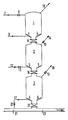
line 7 particulate solid fuel is passed to anatmospheric container 1 by means of an inert carrier gas (N2, CO2), By means of avalve 8 in theline 7 the supply of fuel can be closed. Via aline 9 an inert gas (N2, C02) is passed into the container through porous sintered metal 4, by which inert gas the fuel in thecontainer 1 is fluidized. Through adischarge line 10 the inert carrier gas and the inert fluidizing gas are removed from thecontainer 1, for example to a separator (not shown in the Figure), where any entrained fuel particles are separated from the gas. - By opening a
valve 11 the fuel is passed to alock hopper 2. When a suitable quantity of fuel has been introduced into thelock hopper 2, thevalve 11 is closed. Avalve 13 in aline 12 is opened so that an inert gas flows into the lock hopper viaporous sintered metal 5, by which inert gas the fuel is fluidized and the pressure in thelock hopper 2 increases. When the pressure in thelock hopper 2 is sufficiently high, the supply of the inert gas via thevalve 13 is so arranged that just sufficient gas is introduced to keep the fuel in the fluidized state. In a discharge line 14 avalve 15 is so set that the fluidizing gas introduced via theline 12 can escape so that the pressure of the lock hopper remains unchanged. Subsequently, avalve 16 is opened and the fuel flows from thelock hopper 2 to apressure vessel 3. When all the fuel has left the lock hopper, thevalve 16 is closed again. Thevalve 13 is also closed, whereupon thevalve 15 is opened, owing to which the pressurized gas present escapes via the discharge line 14. When the pressure in thelock hopper 2 is substantially atmospheric, thevalve 15 is also closed. Subsequently, thevalve 11 is opened and thelock hopper 2 is again filled with fuel. - The fuel in the
pressure vessel 3 is kept in the fluidized state by the injection of a carbon monoxide- and hydrogen-containing fluidizing gas via aline 17 and through poroussintered metal 6. By means of avalve 19 in adischarge line 18 it is arranged that such a quantity of gas is removed via thedischarge line 18 from thepressure vessel 3 as is introduced via theline 17. Said discharged gas is passed to a device in which the fuel is ground fine and dried (said device is not shown in the Figure). Avalve 20 is set in such a manner that such a quantity of fuel is introduced into aline 21 that the downward flow rate of the fuel at the level of a horizontal section of thepressure vessel 3 is lower than or equal to the upward velocity at which the fluidizing gas passes the section, so that inert gas that has flowed into the pressure vessel from the lock hopper is displaced by the carbon monoxide- and hydrogen-containing fluidizing gas. The quantity of fluidizing gas introduced into thepressure vessel 3 is arranged by means of a valve 22 in theline 17. - Through the line 21 a carbon monoxide- and hydrogen-containing carrier gas is supplied. Part of said gas is introduced as fluidizing gas into the pressure vessel via the valve 22 and the
line 17. The remaining part serves as carrier gas for the fuel that is passed via thevalve 20 into theline 23. The gas transports the fuel to a reactor (not shown) in which the fuel is partially combusted.
Claims (7)
Applications Claiming Priority (2)
| Application Number | Priority Date | Filing Date | Title |
|---|---|---|---|
| NL8202532 | 1982-06-23 | ||
| NL8202532 | 1982-06-23 |
Publications (3)
| Publication Number | Publication Date |
|---|---|
| EP0101098A2 EP0101098A2 (en) | 1984-02-22 |
| EP0101098A3 EP0101098A3 (en) | 1984-10-17 |
| EP0101098B1 true EP0101098B1 (en) | 1987-01-28 |
Family
ID=19839926
Family Applications (1)
| Application Number | Title | Priority Date | Filing Date |
|---|---|---|---|
| EP83200783A Expired EP0101098B1 (en) | 1982-06-23 | 1983-06-01 | A process for conveying a particulate solid fuel |
Country Status (7)
| Country | Link |
|---|---|
| US (1) | US4955989A (en) |
| EP (1) | EP0101098B1 (en) |
| JP (1) | JPS597821A (en) |
| AU (1) | AU552516B2 (en) |
| CA (1) | CA1208258A (en) |
| DE (1) | DE3369531D1 (en) |
| ZA (1) | ZA834516B (en) |
Cited By (1)
| Publication number | Priority date | Publication date | Assignee | Title |
|---|---|---|---|---|
| DE102008035294A1 (en) * | 2008-07-29 | 2010-02-11 | Siemens Aktiengesellschaft | Dust entry system for covering dust accumulation with gas at high operating pressure, particularly up to ten mega Pascal, has lock that is kept at initial operating pressure |
Families Citing this family (37)
| Publication number | Priority date | Publication date | Assignee | Title |
|---|---|---|---|---|
| GB2156843A (en) * | 1984-02-10 | 1985-10-16 | Hitachi Ltd | Method and apparatus for feeding coal in an integrated power and coal gasification plant |
| JPS61254695A (en) * | 1985-05-07 | 1986-11-12 | Mitsubishi Heavy Ind Ltd | Feeding of coal and char to oxygen blow coal gasification furnace |
| DE3810404A1 (en) * | 1988-03-26 | 1989-10-12 | Krupp Koppers Gmbh | METHOD AND DEVICE FOR PNEUMATICALLY CONVEYING A FINE-GRAINED TO DUST-SHAPED FUEL IN A GASIFICATION REACTOR UNDER INCREASED PRESSURE |
| US5232466A (en) * | 1990-09-27 | 1993-08-03 | Shell Oil Company | Apparatus for producing gas using energy recovering pressurizing system |
| US5160222A (en) * | 1990-11-30 | 1992-11-03 | Tech-Air, Inc. | Pneumatic conveying system |
| EP0606608B1 (en) * | 1993-01-13 | 1998-02-25 | Paul Wurth S.A. | Process for the evacuation of solid residu from a gaspurification installation. |
| FR2705252B1 (en) * | 1993-05-19 | 1995-07-21 | Bp Chemicals Snc | Process for introducing a solid into a reactor and apparatus. |
| US5765728A (en) * | 1995-03-27 | 1998-06-16 | Eastman Kodak Company | Method and apparatus for feeding chopped polyester scrap |
| US7008459B1 (en) * | 1997-04-09 | 2006-03-07 | Arthur P. Fraas | Pretreatment process to remove oxygen from coal en route to a coal pyolysis process as a means of improving the quality of the hydrocarbon liquid product |
| DE19847786A1 (en) * | 1998-10-16 | 2000-04-20 | Degussa | Device and method for filling and emptying a container charged with flammable and aggressive gas |
| RU2312885C2 (en) * | 2002-04-04 | 2007-12-20 | Конокофиллипс Компани | System for desulfurization with the gear of transfer of the sorbent |
| ITBO20020283A1 (en) * | 2002-05-13 | 2003-11-13 | Bl Macchine Automatiche | PROCEDURE AND APPARATUS FOR THE SUPPLY OF POWDER, GRANULAR OR HERBAL PRODUCTS, TO THE DOSING STATIONS OF MACHINES |
| US20090218371A1 (en) * | 2003-03-25 | 2009-09-03 | Wouter Detlof Berggren | Sluice Vessel and Method of Operating Such a Sluice Vessel |
| CN1313578C (en) * | 2005-06-24 | 2007-05-02 | 杨更辰 | Bituminous fine coal transformation feeding method for gas generator and dedicated feeder therefor |
| AT504863B1 (en) * | 2007-01-15 | 2012-07-15 | Siemens Vai Metals Tech Gmbh | METHOD AND APPARATUS FOR GENERATING ELECTRICAL ENERGY IN A GAS AND STEAM TURBINE (GUD) POWER PLANT |
| DE102007020333A1 (en) * | 2007-04-30 | 2008-11-06 | Siemens Ag | Use of pure carbon dioxide as an inerting and conveying medium in dust injection systems for pulverized coal gasification |
| MD3959C2 (en) * | 2007-07-04 | 2010-04-30 | Dinano Ecotechnology Llc | Loader of the carboniferous raw material processing installation |
| US8951314B2 (en) | 2007-10-26 | 2015-02-10 | General Electric Company | Fuel feed system for a gasifier |
| US8992641B2 (en) * | 2007-10-26 | 2015-03-31 | General Electric Company | Fuel feed system for a gasifier |
| PL2231319T3 (en) | 2008-01-16 | 2017-06-30 | Shell Internationale Research Maatschappij B.V. | Process to provide a particulate solid material to a pressurised gasification reactor |
| US8021445B2 (en) | 2008-07-09 | 2011-09-20 | Skye Energy Holdings, Inc. | Upgrading carbonaceous materials |
| JP5675297B2 (en) * | 2010-11-22 | 2015-02-25 | 三菱重工業株式会社 | Gasification facilities and coal gasification combined power generation facilities |
| WO2012073300A1 (en) * | 2010-11-29 | 2012-06-07 | 三菱重工業株式会社 | Gasification device |
| CN103303681B (en) * | 2013-06-07 | 2015-12-23 | 北京神雾环境能源科技集团股份有限公司 | A kind of fine coal pressure-flow system and technique |
| NL2016437B1 (en) | 2016-03-15 | 2017-10-02 | Torrgas Tech B V | Process to prepare a char product and a syngas mixture. |
| NL2019552B1 (en) | 2017-09-14 | 2019-03-27 | Torrgas Tech B V | Process to prepare a char product and a syngas mixture |
| NL2019553B1 (en) | 2017-09-14 | 2019-03-27 | Torrgas Tech B V | Process to prepare an activated carbon product and a syngas mixture |
| US11192734B2 (en) | 2018-03-27 | 2021-12-07 | Mac Trailer Manufacturing, Inc. | Tank having an air piping system and method of loading and unloading the same |
| US10919431B2 (en) | 2018-03-27 | 2021-02-16 | Mac Trailer Manufacturing, Inc. | Dry bulk tank |
| CN111088079B (en) * | 2018-10-23 | 2022-08-09 | 中国石油化工股份有限公司 | Gasification furnace and gasification method of carbonaceous raw material |
| KR20210139221A (en) * | 2019-01-18 | 2021-11-22 | 트리코야 테크놀러지스 엘티디 | Systems and methods for transferring solid particles from a first environment at a first gas pressure to a second environment at a second gas pressure |
| NL2026450B1 (en) | 2019-09-11 | 2022-02-21 | Cramwinckel Michiel | Process to convert a waste polymer product to a gaseous product |
| WO2021084016A1 (en) | 2019-10-29 | 2021-05-06 | Michiel Cramwinckel | Process for a plastic product conversion |
| WO2021083715A1 (en) | 2019-10-31 | 2021-05-06 | Basf Se | Method and system for operating a descending moving bed reactor with flowable granular material |
| WO2023135114A1 (en) | 2022-01-11 | 2023-07-20 | Torrgas Technology B.V | Process to prepare synthesis gas |
| CN114507550B (en) * | 2022-02-23 | 2023-04-25 | 新奥科技发展有限公司 | Pressure control system of voltage transformation device |
| NL2033276B1 (en) | 2022-10-11 | 2023-08-08 | Torrgas Tech B V | Process to continuously prepare a char product |
Family Cites Families (16)
| Publication number | Priority date | Publication date | Assignee | Title |
|---|---|---|---|---|
| US2113774A (en) * | 1934-11-26 | 1938-04-12 | Schmalfeldt Hans | Process for the gasification of dust or fine-grained fuels with circulating gas |
| NL295333A (en) * | 1962-08-11 | |||
| NL299512A (en) * | 1962-10-24 | |||
| US3698882A (en) * | 1970-09-30 | 1972-10-17 | Occidental Petroleum Corp | Continuous process for the conversion of carbonaceous solids into pipeline gas |
| US3775071A (en) * | 1971-06-20 | 1973-11-27 | Hydrocarbon Research Inc | Method for feeding dry coal to superatmospheric pressure |
| US3861885A (en) * | 1971-09-22 | 1975-01-21 | Inst Gas Technology | Carbon black fuel production |
| JPS5513924B2 (en) * | 1972-07-15 | 1980-04-12 | ||
| JPS51618A (en) * | 1974-06-24 | 1976-01-06 | Osaka Transformer Co Ltd | HONETSUKI |
| DE2434526C2 (en) * | 1974-07-18 | 1983-01-13 | Shell Internationale Research Maatschappij B.V., 2501 's-Gravenhage | Method and device for introducing finely divided solid fuel into a gasification chamber under increased pressure |
| US3963426A (en) * | 1974-07-22 | 1976-06-15 | Cameron Engineers, Incorporated | Process for gasifying carbonaceous matter |
| DE2538785C3 (en) * | 1975-09-01 | 1978-09-14 | 2000 Hamburg | Device for saving compressed gas when injecting solids with the aid of pressure vessel conveyors |
| NL7514128A (en) * | 1975-12-04 | 1977-06-07 | Shell Int Research | METHOD AND EQUIPMENT FOR PARTIAL COMBUSTION OF CARBON POWDER. |
| US4094651A (en) * | 1976-05-06 | 1978-06-13 | Donath Ernest E | Process for pseudohydrostatic feeding of solids into a reactor |
| DD147188A3 (en) * | 1977-09-19 | 1981-03-25 | Lutz Barchmann | METHOD AND DEVICE FOR PRESSURE GASIFICATION OF DUST-SOUND FUELS |
| US4397657A (en) * | 1982-04-19 | 1983-08-09 | Allis-Chalmers Corporation | Gas lock system charging particles into a pressurized gasification reactor |
| JPH044687A (en) * | 1990-04-21 | 1992-01-09 | Sachiko Kosaka | Large sized screen display device by cathode ray tube |
-
1983
- 1983-04-21 CA CA000426463A patent/CA1208258A/en not_active Expired
- 1983-06-01 DE DE8383200783T patent/DE3369531D1/en not_active Expired
- 1983-06-01 EP EP83200783A patent/EP0101098B1/en not_active Expired
- 1983-06-21 JP JP58110273A patent/JPS597821A/en active Granted
- 1983-06-21 ZA ZA834516A patent/ZA834516B/en unknown
- 1983-06-21 AU AU15985/83A patent/AU552516B2/en not_active Ceased
-
1987
- 1987-01-23 US US07/008,099 patent/US4955989A/en not_active Expired - Lifetime
Cited By (2)
| Publication number | Priority date | Publication date | Assignee | Title |
|---|---|---|---|---|
| DE102008035294A1 (en) * | 2008-07-29 | 2010-02-11 | Siemens Aktiengesellschaft | Dust entry system for covering dust accumulation with gas at high operating pressure, particularly up to ten mega Pascal, has lock that is kept at initial operating pressure |
| DE102008035294B4 (en) * | 2008-07-29 | 2017-03-02 | Siemens Aktiengesellschaft | Multi-stage dust dosing system for high pressures by means of locks |
Also Published As
| Publication number | Publication date |
|---|---|
| US4955989A (en) | 1990-09-11 |
| DE3369531D1 (en) | 1987-03-05 |
| ZA834516B (en) | 1984-03-28 |
| CA1208258A (en) | 1986-07-22 |
| JPH0258530B2 (en) | 1990-12-10 |
| AU552516B2 (en) | 1986-06-05 |
| JPS597821A (en) | 1984-01-17 |
| EP0101098A3 (en) | 1984-10-17 |
| EP0101098A2 (en) | 1984-02-22 |
| AU1598583A (en) | 1984-01-05 |
Similar Documents
| Publication | Publication Date | Title |
|---|---|---|
| EP0101098B1 (en) | A process for conveying a particulate solid fuel | |
| US4094650A (en) | Integrated catalytic gasification process | |
| US4118204A (en) | Process for the production of an intermediate Btu gas | |
| US4348486A (en) | Production of methanol via catalytic coal gasification | |
| US4322222A (en) | Process for the gasification of carbonaceous materials | |
| US4211669A (en) | Process for the production of a chemical synthesis gas from coal | |
| US4348487A (en) | Production of methanol via catalytic coal gasification | |
| US3991557A (en) | Process for converting high sulfur coal to low sulfur power plant fuel | |
| US4838898A (en) | Method of removal and disposal of fly ash from a high-temperature, high-pressure synthesis gas stream | |
| KR101626185B1 (en) | Method for supplying an entrained-flow gasification reactor with fuel from a reservoir tank | |
| US4229185A (en) | Process for the gasification of carbonaceous materials | |
| US10443005B2 (en) | All-steam gasification with carbon capture | |
| US4040976A (en) | Process of treating carbonaceous material with carbon dioxide | |
| US4531949A (en) | Entrained flow coal gasification process | |
| US5143521A (en) | Method for producing gas using energy recovering coal feeding steps | |
| JP2633678B2 (en) | Method for transporting fine or dusty fuel into a gasification reactor under elevated pressure | |
| US4099933A (en) | Process for the multiple zone gasification of coal | |
| US20120137583A1 (en) | Method for supplying an entrained-flow gasification reactor with carbonaceous fuels | |
| EP0092856B1 (en) | A process for the gasification of a solid carbon-containing fuel | |
| US2868631A (en) | Gasification process | |
| EP0109109B1 (en) | Process for the partial combustion of solid fuel with fly ash recycle | |
| US4019724A (en) | Apparatus for the direct reduction of iron ores | |
| US3700422A (en) | Continuous steam-iron process for making fuel gas | |
| US2623817A (en) | Production of fuel gases | |
| US2654663A (en) | Gasification of carbonaceous solid fuels |
Legal Events
| Date | Code | Title | Description |
|---|---|---|---|
| PUAI | Public reference made under article 153(3) epc to a published international application that has entered the european phase |
Free format text: ORIGINAL CODE: 0009012 |
|
| 17P | Request for examination filed |
Effective date: 19830601 |
|
| AK | Designated contracting states |
Designated state(s): BE DE FR GB IT NL |
|
| PUAL | Search report despatched |
Free format text: ORIGINAL CODE: 0009013 |
|
| AK | Designated contracting states |
Designated state(s): BE DE FR GB IT NL |
|
| GRAA | (expected) grant |
Free format text: ORIGINAL CODE: 0009210 |
|
| AK | Designated contracting states |
Kind code of ref document: B1 Designated state(s): BE DE FR GB IT NL |
|
| ITF | It: translation for a ep patent filed |
Owner name: ING. C. GREGORJ S.P.A. |
|
| REF | Corresponds to: |
Ref document number: 3369531 Country of ref document: DE Date of ref document: 19870305 |
|
| ET | Fr: translation filed | ||
| PLBI | Opposition filed |
Free format text: ORIGINAL CODE: 0009260 |
|
| 26 | Opposition filed |
Opponent name: KRUPP KOPPERS GMBH Effective date: 19871021 |
|
| NLR1 | Nl: opposition has been filed with the epo |
Opponent name: KRUPP KOPPERS GMBH |
|
| PGFP | Annual fee paid to national office [announced via postgrant information from national office to epo] |
Ref country code: FR Payment date: 19900427 Year of fee payment: 8 |
|
| PGFP | Annual fee paid to national office [announced via postgrant information from national office to epo] |
Ref country code: GB Payment date: 19900501 Year of fee payment: 8 |
|
| PGFP | Annual fee paid to national office [announced via postgrant information from national office to epo] |
Ref country code: BE Payment date: 19900607 Year of fee payment: 8 |
|
| ITTA | It: last paid annual fee | ||
| PGFP | Annual fee paid to national office [announced via postgrant information from national office to epo] |
Ref country code: NL Payment date: 19900630 Year of fee payment: 8 |
|
| PGFP | Annual fee paid to national office [announced via postgrant information from national office to epo] |
Ref country code: DE Payment date: 19900711 Year of fee payment: 8 |
|
| RDAG | Patent revoked |
Free format text: ORIGINAL CODE: 0009271 |
|
| STAA | Information on the status of an ep patent application or granted ep patent |
Free format text: STATUS: PATENT REVOKED |
|
| 27W | Patent revoked |
Effective date: 19890118 |
|
| GBPR | Gb: patent revoked under art. 102 of the ep convention designating the uk as contracting state | ||
| NLR2 | Nl: decision of opposition | ||
| BERE | Be: lapsed |
Owner name: SHELL INTERNATIONALE RESEARCH MAATSCHAPPIJ B.V. Effective date: 19910630 |
|
| APAH | Appeal reference modified |
Free format text: ORIGINAL CODE: EPIDOSCREFNO |