EP0102201B1 - In line and bifurcating cardiac pacing lead connector - Google Patents
In line and bifurcating cardiac pacing lead connector Download PDFInfo
- Publication number
- EP0102201B1 EP0102201B1 EP83304432A EP83304432A EP0102201B1 EP 0102201 B1 EP0102201 B1 EP 0102201B1 EP 83304432 A EP83304432 A EP 83304432A EP 83304432 A EP83304432 A EP 83304432A EP 0102201 B1 EP0102201 B1 EP 0102201B1
- Authority
- EP
- European Patent Office
- Prior art keywords
- lead
- connector
- electrodes
- clamping block
- pair
- Prior art date
- Legal status (The legal status is an assumption and is not a legal conclusion. Google has not performed a legal analysis and makes no representation as to the accuracy of the status listed.)
- Expired
Links
Images


Classifications
-
- A—HUMAN NECESSITIES
- A61—MEDICAL OR VETERINARY SCIENCE; HYGIENE
- A61N—ELECTROTHERAPY; MAGNETOTHERAPY; RADIATION THERAPY; ULTRASOUND THERAPY
- A61N1/00—Electrotherapy; Circuits therefor
- A61N1/18—Applying electric currents by contact electrodes
- A61N1/32—Applying electric currents by contact electrodes alternating or intermittent currents
- A61N1/36—Applying electric currents by contact electrodes alternating or intermittent currents for stimulation
- A61N1/372—Arrangements in connection with the implantation of stimulators
- A61N1/375—Constructional arrangements, e.g. casings
- A61N1/3752—Details of casing-lead connections
Definitions
- the present invention relates generally to lead connectors for connecting pacing leads to a pulse generator, e.g. for easily and quickly interconnecting a temporary pacing lead to a pulse generator.
- the lead connector of the Skubitz et al. patent was well suited for interconnecting a temporary bipolar lead to two generally U-shaped elongated connector pins which were affixed to the housing of the lead connector.
- the bipolar lead which was inserted into this lead connector had one electrode area on its end and another electrode area spaced apart from the end, and insulated therefrom, with the entire lead structure being substantially the same diameter. In this manner, the tip electrode contacted one U-shaped permanent connecting pin while the interior spaced apart electrode contacted the other.
- a spring biased pressure plate was forced down by means of a rotatable thumb screw which operated to deflect the spring and the pressure plate so that it engaged the top of the bipolar lead forcing it down into contact with the two generally U-shaped fixed connecting pins.
- This lead connector had a number of desirable features which are desirably retained in the lead connecting device of the present invention.
- One such feature was that the outer housing of the connector was transparent so that medical personnel, such as cardiologists, could see that the pacing lead was properly inserted and secured within the lead connector.
- the lead connector was a very simple design thereby minimizing any cause of failure or misuse, and it was reusable.
- the connector was constructed from readily available materials and the housing was of the plastic injection molded type, formed from polysulfone or similar material.
- the lead connector was designed so that the lead could be semipermanently installed for any period of time.
- the connector could only be used with in-line types of leads and not bifurcated ones.
- the connector was not suited for receiving leads that had electrodes of varying diameters, as is often the case with implantable leads of the in-line variety.
- the lead connector of the present invention retains all of the above- mentioned advantages of the lead connector of the previous Skubitz et al. patent while making is possible to interconnect not only in-line bipolar leads, but also bifurcated leads and in-line leads of varying electrode diameters.
- a lead connector for connecting pacing leads to a pulse generator which has a housing that has at least one inlet opening for an in-line electrode lead and at least one pair of spaced inlet openings for a bifurcated lead; at least one pair of connector electrodes are disposed in the housing and are positioned to contact the electrodes of the leads when they are inserted into the inlet opening; clamping means are associated with the or each pair of connector electrodes and include a threaded shaft that has a free end that extends into the housing, a clamping block through which the free end of the threaded shaft protrudes and a securing means, e.g. a nut, which is threaded onto the free end of the threaded shaft.
- the securing nut has a curved surface and the clamping block has a mating curved surface for the curved surface of the securing nut which receives the securing nut and prevents it from rotating independently of the clamping block.
- the clamping block has a restricted passageway that allows the threaded shaft to pass therethrough so that it may rock to a limited extent relative to the threaded shaft by sliding of its mating curved surface on the curved surface of the securing nutto a position limited by the diameter of said passageway; and the clamping block is driven towards the pair of connector electrodes so as to clamp the inserted lead electrodes between integrally formed surfaces on the clamping block which extend outwardly of said threaded shaft and the pair of connector electrodes upon rotation of its threaded shaft in one direction and said clamping block is driven away from the pair of connector electrodes upon rotation of the threaded shaft in the opposite direction.
- the threaded section 62 of the shaft assembly 48 is captured by a threaded nut 64 of special construction.
- the bottom surface 66 is flat while the upper surface 68 is curved, or domed.
- the surface 68 may be part of a cylinder or it may be hemispherically shaped, if desired.
- the nut 64 should be held non-rotatably in clamping block 52 about the axis of the threaded section 62.
- the clamping block 52 is formed with a recess 67 that has a curved space that generally conforms to the curved surface 68 of the nut.
- the recess 67 leads to a passageway 72 that surrounds the threaded section 62 and is of larger diameter than the diameter of the threaded shaft by an amount that allows the clamping block 52 to rock from the dotted line position through the nominally flat position of FIG. 3 to the full line position as shown in FIG. 4.
- the surface 70 of the recess 67 thus slides on the upper domed surface 68 of the nut 64 when the clamping block rocks to either side.
- the nominally flat position of the clamping block is the position of the block when equal diameter lead electrodes are inserted into the connector and are clamped by the block 52.
- the full line rocked position occurs when the clamping block 52 is secured on a lead that has a larger diameter electrode on the left side of the connector, which is clamped between the arm 74 and the connector electrode 94, than on the right side of the connector, which is clamped by the arm 76 and the connector electrode 96.
- FIG. 5 is an exploded view of a lead connector that corresponds to the lead connector of FIGs. 1-4 with the only difference being that strain relief for the connecting cable 12 is not provided by the strain relief bushing 13, but instead by an internal housing construction.
- strain relief for the connecting cable 12 is not provided by the strain relief bushing 13, but instead by an internal housing construction.
- An opening is provided at the rear of the connector by the notch 78 that is formed in the lower housing half 49b and by a matching notch (not shown) that is formed in the upper housing half 49a. This opening receives the cable 12 therein, and strain relief is provided for this cable by allowing it to wind through the strain relief walls 86, 88.
- the wires 90, 92 of the cable 12 are connected to the electrodes 94, 96 of the lead connector.
- the electrodes 94, 96 are secured in the connector by the receipt of tongues (not shown) which are integrally formed in the lowerhousing half 49b in the grooves 98, 100.
- the clamping block 52 has a curved projection 102 formed on it (FIG. 5) and the lower housing half 49b is formed with an integral wall 104 which has a curved section 106 that corresponds in shape generally to the projection 102.
- the curved wall section 106 thereby prevents the clamping block 52 from rotating when the knob 46 is rotated.
- the wall 104 has two straight wall sections 108 and 110 on opposite sides of the curved wall section 106.
- Another straight wall 112 is integrally formed on the lower housing of 49b and runs generally normal to the wall section 108.
- An opening is formed on the right side of the lead connector, by the semicircular notches 80a, 80b which may receive an in-line lead, such as the lead 114which is illustrated in FIG. 5.
- the lead 114 has a negative electrode tip 116 on it, an insulating ring 118 and a positive electrode 120.
- the lead 114 is inserted into the opening formed by the notches 80a, 80b the end of the electrode tip 116 abuts against the wall section 112 thereby locating the lead electrodes 116, 120 adjacent the connector electrodes 94, 96, respectively. If the lead 114 were a unipolar lead only one of the electrodes 116,120 would be employed.
- the lead electrodes 116, 120 are clamped against the connector electrodes 94, 96 respectively when the knob 46 is rotated in the clockwise direction of the arrow 50.
- the clamping block 52 moves toward the connector electrodes it drives the arms 74, 76 upwardly so that the upper surfaces 75, 77 eventually abut against the lead electrodes 116, 120 and lock them in place against the connector electrodes 94, 96.
- the diameter of the lead electrodes does not have to be the same because the clamping block 52 can rock transversely, as shown in FIG. 4.
- the lead 114 is supported over part of its passageway into the housing of the connector by the channels 122, 124 which are formed on the lower housing half 49b.
- the connector of FIG. 5 may be used to connect a bifurcate lead as shown at 126.
- Lead 126 has electrodes 130, 132 which are inserted in openings 82a,b and 84a,b to abut walls 108 and 110 and are clamped by arms 74,76 against connector electrodes 94, 96.
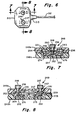
- the lead connector embodiment of the present invention that is shown in FIGs. 6-9 has this capability.
- the lead connector 210 is shown in FIG. 6 with a strain relief bushing 213 and an interconnecting cable 212.
- Two clamping knobs 246 and 247 are shown which are used to provide the damping. Each of the knobs is used to clamp one of the atrial or ventricle interconnecting leads against corresponding lead electrodes in the connector.
- the cross-sectional view of FIG. 7 shows the clamping block 252 and the threaded shaft assembly 248 which is associated with the knob 246. In FIG. 7, two equal diameter leads are shown as being clamped into place in this portion of the connector.
- the construction of the elements as shown in FIG. 7 is substantially identical to those shown in FIG. 3, but the element numbers of FIG. 7 are 200 numbers higher than the element numbers of FIG. 3.
- FIG. 8 is a cross-sectional view of FIG. 6 taken along the lines 8-8 and shows a second clamping block 253 that is associated with the clamping knob 247.
- Assembly 249 is identical to the corresponding elements associated with the knob 246.
- the corresponding element numbers for this clamping block and shaft assembly are the same as those for the clamping block 252 and shaft assembly 248 described in connection with FIG. 7 except that they are one number higher than the corresponding element numbers of FIG. 7.
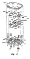
- FIG. 9 is an exploded view of the connector of FIGs. 6-8 in which the corresponding element numbers referred to in FIGs.
- both atrial and ventricular leads may be connected through the cable to the pulse generator.
- the left-hand section of the lead connector were employed to clamp the atrial lead, then the right-hand section could be employed to clamp the ventricle lead.
- the connector of FIGs. 6-8 it is not necessary for both the atrial and ventricular leads to be of the same type.
- they may both be bifurcated leads, they may both be in-line leads or alternately, one of them may be a bifurcated lead while the other is an in-line lead. This universality is an important feature of the lead connector.
- the cable 212 may be inserted into the lead connector 210 through the opening formed by the notch 278 and a similar notch in the upper housing half 249a (not shown with strain relief in the embodiment of FIG. 9 again being provided by the walls 286, 288.
- a bifurcated lead may be inserted into the housing through the channels 303, 305 so as to make contact respectively with the electrodes 294, 296.
- an in-line bipolar lead may make connection with the electrodes 294, 296 by insertion through the rear of the housing in the channel 309 or through the front of the housing in the channel 311. Unlike the connector of FIGs. 1-5, however, there are no stop walls which assist in aligning the lead electrodes with the connector electrodes.
- the projection 302 on the clamping block 252 in the connector of FIGs. 6-9 fits into a curved wall section 313 which corresponds to the shape of the projection 302 to prevent the clamping block 252 from rotating when it is drawn towards the electrodes 294, 296.
- the clamping block 252 may rock in the manner described with reference to the clamping block 52 of FIG. 3 so that lead electrodes of different diameters may be clamped between the arms 274, 276 and the electrodes 294, 296 in the connector.
- a ventricular lead may be connected to the electrodes 295, 297 on the right-hand section of the connector. This is done by passing bifurcated leads through the channels 315,317 or by passing in-line leads through the lead channel 319 in the front of the connector, or the lead connector 321 in the rear of the connector.
- these leads are inserted into the housing, they are correspondingly clamped by the arms 277, 275 of the clamping block 253 against the electrodes 295, 297.
- the wires 290, 292 will thus be associated with the atrial pacing lead while the wires 291, 293 will be associated with the ventricular lead, in this instance.
- a unipolar lead may pass through the passageway 315 and over the channel 224 for connection to the electrode 294.
- a lead passing through the channel 303 and across the channel 224 may be connected to the electrode 295.
- a second unipolar lead could then be connected either to the electrode 296 through the channel 305 or to the electrode 297 through the channel 317.
Description
- The present invention relates generally to lead connectors for connecting pacing leads to a pulse generator, e.g. for easily and quickly interconnecting a temporary pacing lead to a pulse generator.
- In the past pulse generators have generally utilized binding post or squeeze connectors for temporary connection which proved to be inadequate for making connection to more advanced temporary pacing leads in order to make connection to an external pacemaker. The need to easily and quickly interconnect the temporary leads to the external pacemaker without complex interconnecting cable or interconnecting structure was met by the lead connector of our U.S. Patent No. 4,245,642 (Skubitz et al.).
- The lead connector of the Skubitz et al. patent was well suited for interconnecting a temporary bipolar lead to two generally U-shaped elongated connector pins which were affixed to the housing of the lead connector. The bipolar lead which was inserted into this lead connector had one electrode area on its end and another electrode area spaced apart from the end, and insulated therefrom, with the entire lead structure being substantially the same diameter. In this manner, the tip electrode contacted one U-shaped permanent connecting pin while the interior spaced apart electrode contacted the other. A spring biased pressure plate was forced down by means of a rotatable thumb screw which operated to deflect the spring and the pressure plate so that it engaged the top of the bipolar lead forcing it down into contact with the two generally U-shaped fixed connecting pins.
- This lead connector had a number of desirable features which are desirably retained in the lead connecting device of the present invention. One such feature was that the outer housing of the connector was transparent so that medical personnel, such as cardiologists, could see that the pacing lead was properly inserted and secured within the lead connector. The lead connector was a very simple design thereby minimizing any cause of failure or misuse, and it was reusable. The connector was constructed from readily available materials and the housing was of the plastic injection molded type, formed from polysulfone or similar material. The lead connector was designed so that the lead could be semipermanently installed for any period of time.
- While all of these advantages were present in the lead connector of the Skubitz et al. patent, No. 4,245,642 the connector could only be used with in-line types of leads and not bifurcated ones. In addition, the connector was not suited for receiving leads that had electrodes of varying diameters, as is often the case with implantable leads of the in-line variety. The lead connector of the present invention retains all of the above- mentioned advantages of the lead connector of the previous Skubitz et al. patent while making is possible to interconnect not only in-line bipolar leads, but also bifurcated leads and in-line leads of varying electrode diameters.
- A lead connector for connecting pacing leads to a pulse generator is provided which has a housing that has at least one inlet opening for an in-line electrode lead and at least one pair of spaced inlet openings for a bifurcated lead; at least one pair of connector electrodes are disposed in the housing and are positioned to contact the electrodes of the leads when they are inserted into the inlet opening; clamping means are associated with the or each pair of connector electrodes and include a threaded shaft that has a free end that extends into the housing, a clamping block through which the free end of the threaded shaft protrudes and a securing means, e.g. a nut, which is threaded onto the free end of the threaded shaft. The securing nut has a curved surface and the clamping block has a mating curved surface for the curved surface of the securing nut which receives the securing nut and prevents it from rotating independently of the clamping block. The clamping block has a restricted passageway that allows the threaded shaft to pass therethrough so that it may rock to a limited extent relative to the threaded shaft by sliding of its mating curved surface on the curved surface of the securing nutto a position limited by the diameter of said passageway; and the clamping block is driven towards the pair of connector electrodes so as to clamp the inserted lead electrodes between integrally formed surfaces on the clamping block which extend outwardly of said threaded shaft and the pair of connector electrodes upon rotation of its threaded shaft in one direction and said clamping block is driven away from the pair of connector electrodes upon rotation of the threaded shaft in the opposite direction.
- Certain embodiments of the invention will now be described by way of example and with reference to the drawings, in which:
- FIG. 1 is a plan view that shows a pacing lead connected between a pulse generator and one embodiment of the lead connector of the present invention;
- FIG. 2 is an enlarged plan view of the lead connector of FIG. 1;
- FIG. 3 is a cross-sectional view of the lead connector of FIG. 2 taken along the lines 3-3 of FIG. 2;
- FIG. 4 is an enlarged detail of FIG. 3;
- FIG. 5 is an exploded view of a lead connector that corresponds to the lead connector of FIG. 1;
- FIG. 6 is a plan view of an alternative lead connector which is capable of receiving both atrial and ventricular pacing leads;
- FIG. 7 is a cross-sectional view of the lead connector of FIG. 6 taken along the lines 7-7 of FIG. 6;
- FIG. 8 is a cross-sectional view of the lead connector of FIG. 6 taken along the lines 8-8 of FIG. 6; and
- FIG. 9 is an exploded view of a lead connector that corresponds to the lead connector of FIG. 6.
- FIG. 1 shows a
lead connector 10 constructed in accordance with the present invention which is coupled through acable 12 to anexternal pulse generator 14. The prior lead connector of the Skubitz et al. patent, No. 4,245,642 was constructed so that the two connecting pins extending through the housing of the connector case would be inserted directly into the external pulse generator so that the connector would be fixed firmly on the top of the generator. It has been found, however, that this limits the usefulness of the device and that it is more desirable for the lead connector to be connected to a cable and then throughseparate connector pins - FIG. 2 shows a
lead connector 10 constructed in accordance with the present invention. A strain relief bushing 13 relieves strain on thecable 12. The upper surface 40 of thelead connector 10 is marked with aplus mark 42 and aminus mark 44 which indicate the proper polarity of the leads. Aclamping knob 46 is secured to ashaft assembly 48 which projects into the interior of thehousing 49 which is formed of upper andlower housing halves knob 46 is rotated in the clockwise direction, indicated by thearrow 50 in FIG. 2, a clamping block 52 (shown in FIG. 3), is drawn upwardly so as to clamp on to the electrodes of the leads thereby firmly engaging them with the electrodes in the lead connector. - FIG. 4 is an enlarged view of the
clamping block 52 and theshaft assembly 48 of FIG. 3. Theshaft assembly 48 has an enlargedcylindrical portion 56 which receives theknob 46. Thecylindrical portion 56 has an enlargedring 58 at its lower end which is retained in agroove 60 in theupper housing half 49a to keep the shaft assembly from being removed from the housing. A lower threadedsection 62 of theshaft assembly 48 extends into thehousing 49. - The threaded
section 62 of theshaft assembly 48 is captured by a threadednut 64 of special construction. Thebottom surface 66 is flat while theupper surface 68 is curved, or domed. Thesurface 68 may be part of a cylinder or it may be hemispherically shaped, if desired. Thenut 64 should be held non-rotatably inclamping block 52 about the axis of the threadedsection 62. Theclamping block 52 is formed with arecess 67 that has a curved space that generally conforms to thecurved surface 68 of the nut. Therecess 67 leads to apassageway 72 that surrounds the threadedsection 62 and is of larger diameter than the diameter of the threaded shaft by an amount that allows theclamping block 52 to rock from the dotted line position through the nominally flat position of FIG. 3 to the full line position as shown in FIG. 4. Thesurface 70 of therecess 67 thus slides on theupper domed surface 68 of thenut 64 when the clamping block rocks to either side. The nominally flat position of the clamping block is the position of the block when equal diameter lead electrodes are inserted into the connector and are clamped by theblock 52. The full line rocked position occurs when theclamping block 52 is secured on a lead that has a larger diameter electrode on the left side of the connector, which is clamped between thearm 74 and theconnector electrode 94, than on the right side of the connector, which is clamped by thearm 76 and theconnector electrode 96. - FIG. 5 is an exploded view of a lead connector that corresponds to the lead connector of FIGs. 1-4 with the only difference being that strain relief for the connecting
cable 12 is not provided by the strain relief bushing 13, but instead by an internal housing construction. In this embodiment there are four openings through the housing into the interior of the lead connector. These openings are formed by semi-circular notches on the upper andlower housing halves notch 78 that is formed in thelower housing half 49b and by a matching notch (not shown) that is formed in theupper housing half 49a. This opening receives thecable 12 therein, and strain relief is provided for this cable by allowing it to wind through thestrain relief walls wires cable 12 are connected to theelectrodes electrodes lowerhousing half 49b in thegrooves - The
clamping block 52 has acurved projection 102 formed on it (FIG. 5) and thelower housing half 49b is formed with anintegral wall 104 which has acurved section 106 that corresponds in shape generally to theprojection 102. Thecurved wall section 106 thereby prevents theclamping block 52 from rotating when theknob 46 is rotated. Thewall 104 has twostraight wall sections curved wall section 106. Anotherstraight wall 112 is integrally formed on the lower housing of 49b and runs generally normal to thewall section 108. An opening is formed on the right side of the lead connector, by thesemicircular notches 80a, 80b which may receive an in-line lead, such as the lead 114which is illustrated in FIG. 5. Thelead 114 in FIG. 5 is a bipolar lead which has two uniform diameter electrodes, but the lead could also be a unipolar lead, or a bipolar lead with different diameter electrodes. Thelead 114 has anegative electrode tip 116 on it, an insulatingring 118 and apositive electrode 120. When thelead 114 is inserted into the opening formed by thenotches 80a, 80b the end of theelectrode tip 116 abuts against thewall section 112 thereby locating thelead electrodes connector electrodes lead 114 were a unipolar lead only one of the electrodes 116,120 would be employed. - The
lead electrodes connector electrodes knob 46 is rotated in the clockwise direction of thearrow 50. This causes theclamping block 52 to be drawn upwardly (FIG. 4) on the threadedsection 62 of theshaft assembly 48, due to the interaction of the threadedsection 62 and thenut 64 which is retained in the clamping block. As the clampingblock 52 moves toward the connector electrodes it drives thearms upper surfaces 75, 77 eventually abut against thelead electrodes connector electrodes clamping block 52 can rock transversely, as shown in FIG. 4. Thelead 114 is supported over part of its passageway into the housing of the connector by thechannels lower housing half 49b. - The connector of FIG. 5 may be used to connect a bifurcate lead as shown at 126.
Lead 126 haselectrodes openings 82a,b and 84a,b toabut walls arms connector electrodes - With modern cardiac pacing generators it is often desirable to be able to interconnect both atrial and ventricular temporary pacing leads to a pulse generator. The lead connector embodiment of the present invention that is shown in FIGs. 6-9 has this capability. The
lead connector 210 is shown in FIG. 6 with astrain relief bushing 213 and an interconnectingcable 212. Two clampingknobs clamping block 252 and the threadedshaft assembly 248 which is associated with theknob 246. In FIG. 7, two equal diameter leads are shown as being clamped into place in this portion of the connector. The construction of the elements as shown in FIG. 7 is substantially identical to those shown in FIG. 3, but the element numbers of FIG. 7 are 200 numbers higher than the element numbers of FIG. 3. - FIG. 8 is a cross-sectional view of FIG. 6 taken along the lines 8-8 and shows a
second clamping block 253 that is associated with the clampingknob 247.Assembly 249 is identical to the corresponding elements associated with theknob 246. The corresponding element numbers for this clamping block and shaft assembly are the same as those for theclamping block 252 andshaft assembly 248 described in connection with FIG. 7 except that they are one number higher than the corresponding element numbers of FIG. 7. The operation and construction of the clamping arrangements of FIGs. 7 and 8 therefore follow the description previously contained herein with regard to the clamping provisions of FIG. 3, taking into account the aforementioned element number changes. FIG. 9 is an exploded view of the connector of FIGs. 6-8 in which the corresponding element numbers referred to in FIGs. 7 and 8 are employed. With this connector embodiment, however, both atrial and ventricular leads may be connected through the cable to the pulse generator. For example, if the left-hand section of the lead connector were employed to clamp the atrial lead, then the right-hand section could be employed to clamp the ventricle lead. With the connector of FIGs. 6-8 it is not necessary for both the atrial and ventricular leads to be of the same type. Thus, they may both be bifurcated leads, they may both be in-line leads or alternately, one of them may be a bifurcated lead while the other is an in-line lead. This universality is an important feature of the lead connector. Thecable 212 may be inserted into thelead connector 210 through the opening formed by thenotch 278 and a similar notch in theupper housing half 249a (not shown with strain relief in the embodiment of FIG. 9 again being provided by thewalls channels electrodes electrodes channel 309 or through the front of the housing in thechannel 311. Unlike the connector of FIGs. 1-5, however, there are no stop walls which assist in aligning the lead electrodes with the connector electrodes. Theprojection 302 on theclamping block 252 in the connector of FIGs. 6-9 fits into acurved wall section 313 which corresponds to the shape of theprojection 302 to prevent theclamping block 252 from rotating when it is drawn towards theelectrodes clamping block 252 may rock in the manner described with reference to theclamping block 52 of FIG. 3 so that lead electrodes of different diameters may be clamped between thearms electrodes - In a similar manner, if an atrial lead is connected on the left-hand section of the connector a ventricular lead may be connected to the
electrodes lead channel 319 in the front of the connector, or thelead connector 321 in the rear of the connector. When these leads are inserted into the housing, they are correspondingly clamped by thearms clamping block 253 against theelectrodes wires wires - Although the invention has been described wherein the atrial and ventricular connecting leads are connected in separate sides of the connector, it is possible with the connector constructed in the manner illustrated in FIG. 9 to make various other combinations of lead connections involving a bipolar or unipolar leads.
- For example, a unipolar lead may pass through the
passageway 315 and over thechannel 224 for connection to theelectrode 294. In a similar manner, a lead passing through thechannel 303 and across thechannel 224 may be connected to theelectrode 295. A second unipolar lead could then be connected either to theelectrode 296 through thechannel 305 or to theelectrode 297 through thechannel 317. Thus, although the connector of FIGs. 6-9 is an extremely simple construction, it has a high degree of adaptability since it can connect different types of leads, and even leads of different diameters, to a cardiac pacing pulse generator in a variety of connection configurations.
Claims (3)
Applications Claiming Priority (2)
| Application Number | Priority Date | Filing Date | Title |
|---|---|---|---|
| US06/404,246 US4466441A (en) | 1982-08-02 | 1982-08-02 | In-line and bifurcated cardiac pacing lead connector |
| US404246 | 1982-08-02 |
Publications (2)
| Publication Number | Publication Date |
|---|---|
| EP0102201A1 EP0102201A1 (en) | 1984-03-07 |
| EP0102201B1 true EP0102201B1 (en) | 1987-01-07 |
Family
ID=23598799
Family Applications (1)
| Application Number | Title | Priority Date | Filing Date |
|---|---|---|---|
| EP83304432A Expired EP0102201B1 (en) | 1982-08-02 | 1983-08-01 | In line and bifurcating cardiac pacing lead connector |
Country Status (3)
| Country | Link |
|---|---|
| US (1) | US4466441A (en) |
| EP (1) | EP0102201B1 (en) |
| DE (1) | DE3368872D1 (en) |
Families Citing this family (49)
| Publication number | Priority date | Publication date | Assignee | Title |
|---|---|---|---|---|
| US4942876A (en) * | 1988-08-02 | 1990-07-24 | Telectronics, N.V. | Pacemaker terminal apparatus |
| US5069209A (en) * | 1990-09-21 | 1991-12-03 | Telectronics Pacing Systems, Inc. | Electrical terminal |
| US5328442A (en) * | 1992-11-20 | 1994-07-12 | Siemens Pacesetter, Inc. | System and method for stimulating a heart having undergone cardiac myoplasty using a single-chamber pacemaker |
| US5557210A (en) * | 1992-11-20 | 1996-09-17 | Pacesetter, Inc. | Universal cable connector for temporarily connecting implantable stimulation leads and implantable stimulation devices with a non-implantable system analyzer |
| US5383913A (en) * | 1993-04-21 | 1995-01-24 | Schiff; Steven M. | Bidirectional lead connector for left or right sided implantation of pacemakers and/or other implantable electrophysiologic devices and a method for using the same |
| US5782892A (en) * | 1997-04-25 | 1998-07-21 | Medtronic, Inc. | Medical lead adaptor for external medical device |
| US5931861A (en) * | 1997-04-25 | 1999-08-03 | Medtronic, Inc. | Medical lead adaptor having rotatable locking clip mechanism |
| US6397108B1 (en) | 2000-04-03 | 2002-05-28 | Medtronic Inc. | Safety adaptor for temporary medical leads |
| US6854994B2 (en) * | 2001-04-19 | 2005-02-15 | Medtronic, Inc. | Medical electrical lead connector arrangement including anti-rotation means |
| US6921295B2 (en) * | 2001-04-19 | 2005-07-26 | Medtronic, Inc. | Medical lead extension and connection system |
| US20030040784A1 (en) * | 2001-08-21 | 2003-02-27 | Pasternak Scott Vincent | Medical lead adapter for storing, isolating, identifying, and connecting temporary pacing leads |
| US20030120327A1 (en) * | 2001-12-20 | 2003-06-26 | Mark Tobritzhofer | Medical lead adaptor assembly with retainer |
| US20030199948A1 (en) * | 2002-04-19 | 2003-10-23 | Kokones Scott B. | Multiport neurological screening cable |
| EP1667764B1 (en) * | 2003-09-16 | 2014-02-26 | Boston Scientific Neuromodulation Corporation | Axial to planar lead conversion device and method |
| WO2009114607A1 (en) * | 2008-03-12 | 2009-09-17 | Boston Scientific Neuromodulation Corporation | Low-profile connector for a neurostimulation lead |
| WO2009148937A1 (en) * | 2008-06-03 | 2009-12-10 | Medtronic, Inc. | Lead extension having connector configured to receive two leads |
| US8548601B2 (en) | 2008-09-15 | 2013-10-01 | Boston Scientific Neuromodulation Corporation | Lead connection system for an implantable electrical stimulation system and methods for making and using the systems |
| US8452037B2 (en) | 2010-05-05 | 2013-05-28 | Apple Inc. | Speaker clip |
| US8989428B2 (en) | 2011-08-31 | 2015-03-24 | Apple Inc. | Acoustic systems in electronic devices |
| US8879761B2 (en) | 2011-11-22 | 2014-11-04 | Apple Inc. | Orientation-based audio |
| US9820033B2 (en) | 2012-09-28 | 2017-11-14 | Apple Inc. | Speaker assembly |
| US8858271B2 (en) * | 2012-10-18 | 2014-10-14 | Apple Inc. | Speaker interconnect |
| US9357299B2 (en) | 2012-11-16 | 2016-05-31 | Apple Inc. | Active protection for acoustic device |
| US9451354B2 (en) | 2014-05-12 | 2016-09-20 | Apple Inc. | Liquid expulsion from an orifice |
| US9900698B2 (en) | 2015-06-30 | 2018-02-20 | Apple Inc. | Graphene composite acoustic diaphragm |
| US9956394B2 (en) | 2015-09-10 | 2018-05-01 | Boston Scientific Neuromodulation Corporation | Connectors for electrical stimulation systems and methods of making and using |
| US10342983B2 (en) | 2016-01-14 | 2019-07-09 | Boston Scientific Neuromodulation Corporation | Systems and methods for making and using connector contact arrays for electrical stimulation systems |
| US10201713B2 (en) | 2016-06-20 | 2019-02-12 | Boston Scientific Neuromodulation Corporation | Threaded connector assembly and methods of making and using the same |
| US10307602B2 (en) | 2016-07-08 | 2019-06-04 | Boston Scientific Neuromodulation Corporation | Threaded connector assembly and methods of making and using the same |
| US10543374B2 (en) | 2016-09-30 | 2020-01-28 | Boston Scientific Neuromodulation Corporation | Connector assemblies with bending limiters for electrical stimulation systems and methods of making and using same |
| US10905871B2 (en) | 2017-01-27 | 2021-02-02 | Boston Scientific Neuromodulation Corporation | Lead assemblies with arrangements to confirm alignment between terminals and contacts |
| US11033735B2 (en) | 2017-02-08 | 2021-06-15 | Ian Nolan Hess | Pacer wire management devices and methods |
| US10814136B2 (en) | 2017-02-28 | 2020-10-27 | Boston Scientific Neuromodulation Corporation | Toolless connector for latching stimulation leads and methods of making and using |
| US10603499B2 (en) | 2017-04-07 | 2020-03-31 | Boston Scientific Neuromodulation Corporation | Tapered implantable lead and connector interface and methods of making and using |
| EP3658228A1 (en) | 2017-07-25 | 2020-06-03 | Boston Scientific Neuromodulation Corporation | Systems and methods for making and using an enhanced connector of an electrical stimulation system |
| US11045656B2 (en) | 2017-09-15 | 2021-06-29 | Boston Scientific Neuromodulation Corporation | Biased lead connector for operating room cable assembly and methods of making and using |
| US10639485B2 (en) | 2017-09-15 | 2020-05-05 | Boston Scientific Neuromodulation Corporation | Actuatable lead connector for an operating room cable assembly and methods of making and using |
| US11307661B2 (en) | 2017-09-25 | 2022-04-19 | Apple Inc. | Electronic device with actuators for producing haptic and audio output along a device housing |
| US11139603B2 (en) | 2017-10-03 | 2021-10-05 | Boston Scientific Neuromodulation Corporation | Connectors with spring contacts for electrical stimulation systems and methods of making and using same |
| KR20200067846A (en) * | 2017-10-06 | 2020-06-12 | 메드트로닉 좀드 인코퍼레이티드 | Pleasit stimulation and recording electrode assembly |
| US11103712B2 (en) | 2018-01-16 | 2021-08-31 | Boston Scientific Neuromodulation Corporation | Connector assemblies with novel spacers for electrical stimulation systems and methods of making and using same |
| WO2019217415A1 (en) | 2018-05-11 | 2019-11-14 | Boston Scientific Neuromodulation Corporation | Connector assembly for an electrical stimulation system |
| US10757491B1 (en) | 2018-06-11 | 2020-08-25 | Apple Inc. | Wearable interactive audio device |
| US10873798B1 (en) | 2018-06-11 | 2020-12-22 | Apple Inc. | Detecting through-body inputs at a wearable audio device |
| US11334032B2 (en) | 2018-08-30 | 2022-05-17 | Apple Inc. | Electronic watch with barometric vent |
| US11561144B1 (en) | 2018-09-27 | 2023-01-24 | Apple Inc. | Wearable electronic device with fluid-based pressure sensing |
| CN114399015A (en) | 2019-04-17 | 2022-04-26 | 苹果公司 | Wireless locatable tag |
| US11357992B2 (en) | 2019-05-03 | 2022-06-14 | Boston Scientific Neuromodulation Corporation | Connector assembly for an electrical stimulation system and methods of making and using |
| EP4182007A1 (en) * | 2020-07-15 | 2023-05-24 | Case Western Reserve University | Implantable in-line high density connector |
Family Cites Families (5)
| Publication number | Priority date | Publication date | Assignee | Title |
|---|---|---|---|---|
| AT224727B (en) * | 1960-07-27 | 1962-12-10 | Hirschmann Radiotechnik | Double clamp for connecting electrical lines |
| US4105037A (en) * | 1977-05-06 | 1978-08-08 | Biotronik Mess- Und Therapiegerate Gmbh & Co. | Releasable electrical connecting means for the electrode terminal of an implantable artificial cardiac pacemaker |
| IT7821073V0 (en) * | 1978-03-09 | 1978-03-09 | Ates Componenti Elettron | CLAMP FOR FIXING A SEMICONDUCTOR DEVICE TO A HEAT SINK. |
| US4276882A (en) * | 1979-05-18 | 1981-07-07 | Medtronic, Inc. | Lead anchoring device |
| US4245642A (en) * | 1979-06-28 | 1981-01-20 | Medtronic, Inc. | Lead connector |
-
1982
- 1982-08-02 US US06/404,246 patent/US4466441A/en not_active Expired - Fee Related
-
1983
- 1983-08-01 EP EP83304432A patent/EP0102201B1/en not_active Expired
- 1983-08-01 DE DE8383304432T patent/DE3368872D1/en not_active Expired
Also Published As
| Publication number | Publication date |
|---|---|
| US4466441A (en) | 1984-08-21 |
| DE3368872D1 (en) | 1987-02-12 |
| EP0102201A1 (en) | 1984-03-07 |
Similar Documents
| Publication | Publication Date | Title |
|---|---|---|
| EP0102201B1 (en) | In line and bifurcating cardiac pacing lead connector | |
| US7467013B2 (en) | Ring connector for implantable medical devices | |
| US6006135A (en) | Apparatus for interconnecting implantable electrical leads and medical device | |
| US6984145B1 (en) | Implantable medical device connector assembly with side-actuated lead body affixation | |
| US4848346A (en) | Pacemaker connector system | |
| US5679026A (en) | Header adapter for an implantable cardiac stimulation device | |
| US7195523B2 (en) | Electrical conductive path for a medical electronics device | |
| US7585190B2 (en) | Electrical connector and devices using the same | |
| US7515964B1 (en) | Multi-directional bore configuration header | |
| US4226244A (en) | Electrical connector for implantable electrical generators | |
| CA2096056C (en) | Diagnostic connector port for a pulse generator | |
| EP1651306A1 (en) | Small format connector clip of an implantable medical device | |
| US6575759B1 (en) | Rapid locking connector head for active implantable medical devices | |
| KR20210089216A (en) | High Current Plug Connectors and Plug Connector Systems | |
| EP1501171A1 (en) | Plug connector device for compact servomotors | |
| EP0413849A1 (en) | Rotation detection device for a commutator motor excited by permanent magnets or protruding poles | |
| US6390843B1 (en) | Lead lock for implantable medical device | |
| GB2127629A (en) | Implantable medical device with sealed electrical coupling | |
| DE3914677C2 (en) | ||
| EP0339802A3 (en) | Removable filter array for multiway connectors | |
| US3694799A (en) | Electrical cable connector | |
| JPH11120976A (en) | Battery connecting structure for electric vehicle | |
| US6907292B1 (en) | Device in connection with pacers | |
| EP3595771B1 (en) | Adapter assemblies for implantable medical electrical systems | |
| JP2001102035A (en) | Terminal connecting structure of battery |
Legal Events
| Date | Code | Title | Description |
|---|---|---|---|
| PUAI | Public reference made under article 153(3) epc to a published international application that has entered the european phase |
Free format text: ORIGINAL CODE: 0009012 |
|
| AK | Designated contracting states |
Designated state(s): DE FR GB IT NL SE |
|
| 17P | Request for examination filed |
Effective date: 19840817 |
|
| 17Q | First examination report despatched |
Effective date: 19860408 |
|
| GRAA | (expected) grant |
Free format text: ORIGINAL CODE: 0009210 |
|
| ITF | It: translation for a ep patent filed |
Owner name: BARZANO' E ZANARDO ROMA S.P.A. |
|
| AK | Designated contracting states |
Kind code of ref document: B1 Designated state(s): DE FR GB IT NL SE |
|
| REF | Corresponds to: |
Ref document number: 3368872 Country of ref document: DE Date of ref document: 19870212 |
|
| ET | Fr: translation filed | ||
| PLBE | No opposition filed within time limit |
Free format text: ORIGINAL CODE: 0009261 |
|
| STAA | Information on the status of an ep patent application or granted ep patent |
Free format text: STATUS: NO OPPOSITION FILED WITHIN TIME LIMIT |
|
| 26N | No opposition filed | ||
| ITTA | It: last paid annual fee | ||
| EAL | Se: european patent in force in sweden |
Ref document number: 83304432.4 |
|
| PGFP | Annual fee paid to national office [announced via postgrant information from national office to epo] |
Ref country code: SE Payment date: 19950713 Year of fee payment: 13 |
|
| PGFP | Annual fee paid to national office [announced via postgrant information from national office to epo] |
Ref country code: FR Payment date: 19950717 Year of fee payment: 13 |
|
| PGFP | Annual fee paid to national office [announced via postgrant information from national office to epo] |
Ref country code: NL Payment date: 19950719 Year of fee payment: 13 |
|
| PGFP | Annual fee paid to national office [announced via postgrant information from national office to epo] |
Ref country code: DE Payment date: 19950725 Year of fee payment: 13 |
|
| PGFP | Annual fee paid to national office [announced via postgrant information from national office to epo] |
Ref country code: GB Payment date: 19950727 Year of fee payment: 13 |
|
| PG25 | Lapsed in a contracting state [announced via postgrant information from national office to epo] |
Ref country code: GB Effective date: 19960801 |
|
| PG25 | Lapsed in a contracting state [announced via postgrant information from national office to epo] |
Ref country code: SE Effective date: 19960802 |
|
| PG25 | Lapsed in a contracting state [announced via postgrant information from national office to epo] |
Ref country code: NL Effective date: 19970301 |
|
| GBPC | Gb: european patent ceased through non-payment of renewal fee |
Effective date: 19960801 |
|
| PG25 | Lapsed in a contracting state [announced via postgrant information from national office to epo] |
Ref country code: FR Effective date: 19970430 |
|
| NLV4 | Nl: lapsed or anulled due to non-payment of the annual fee |
Effective date: 19970301 |
|
| PG25 | Lapsed in a contracting state [announced via postgrant information from national office to epo] |
Ref country code: DE Effective date: 19970501 |
|
| EUG | Se: european patent has lapsed |
Ref document number: 83304432.4 |
|
| REG | Reference to a national code |
Ref country code: FR Ref legal event code: ST |