EP0102700A2 - User friendly central control display for a multi-station document inserter - Google Patents
User friendly central control display for a multi-station document inserter Download PDFInfo
- Publication number
- EP0102700A2 EP0102700A2 EP83303767A EP83303767A EP0102700A2 EP 0102700 A2 EP0102700 A2 EP 0102700A2 EP 83303767 A EP83303767 A EP 83303767A EP 83303767 A EP83303767 A EP 83303767A EP 0102700 A2 EP0102700 A2 EP 0102700A2
- Authority
- EP
- European Patent Office
- Prior art keywords
- inserter
- central control
- control display
- document
- feeder
- Prior art date
- Legal status (The legal status is an assumption and is not a legal conclusion. Google has not performed a legal analysis and makes no representation as to the accuracy of the status listed.)
- Withdrawn
Links
Images


Classifications
-
- B—PERFORMING OPERATIONS; TRANSPORTING
- B07—SEPARATING SOLIDS FROM SOLIDS; SORTING
- B07C—POSTAL SORTING; SORTING INDIVIDUAL ARTICLES, OR BULK MATERIAL FIT TO BE SORTED PIECE-MEAL, e.g. BY PICKING
- B07C1/00—Measures preceding sorting according to destination
-
- B—PERFORMING OPERATIONS; TRANSPORTING
- B43—WRITING OR DRAWING IMPLEMENTS; BUREAU ACCESSORIES
- B43M—BUREAU ACCESSORIES NOT OTHERWISE PROVIDED FOR
- B43M3/00—Devices for inserting documents into envelopes
- B43M3/04—Devices for inserting documents into envelopes automatic
Definitions
- the present invention relates to document inserters, and more particularly to multi-station document inserters.
- Known multi-station document inserters employ discrete elements with individual module display lights to indicate a malfunction. When such lights are lighted, the operater must check the appropriate module in an attempt to determine the cause of the malfunction Further, once the inserter configuration is fixed, the inserter must be rewired to change its operation.
- apparatus for providing a user friendly central control display in a multi-station document inserter comprising:
- a method and associated apparatus for providing a user friendly central control display for a multi-station document inserter, comprising the steps of interconnecting a central control display to the inserter, displaying inserter operating functions on the central control display, activating the inserter through the central control display to perform programmed inserter operating functions, and displaying fault locations and descriptions on the central control display in human readable form.
- the inserter operator can also reconfigure the inserter through switches in the central control display.
- a multi-station document inserter is illustrated as 10.
- a central control display 12 is electrically connected to the inserter 10.
- the central control display 12 is a finger touch display, such as Fluke Model 1780A InfoTouch Display.
- Both the multi-station document inserter 10 and central control display 12 are of the type disclosed in copending U.S. patent application Serial No. 394 388 filed on 1st July 1982 in the names of Peter N. Piotroski and John M. Gomes, European Patent Application Number (E59/13), entitled UNIVERSAL MULTI-STATION DOCUMENT INSERTER, the disclosure of which is incorporated herein by reference.
- the central control display 12 is electrically connected to the supervisory control circuit of the multi-station document inserter 10 through a RS232C standard communication line.
- the central control display 12 provides an operator or user with certain switches which when activated cause the inserter 10 to undergo certain routines and provide displays in human readable form.
- th E central control display 12 is shown with certain information displayed upon Power U p. Specifically, the following switches are displayed:
- the display shall display information enabling the operator to determine:
- a maintenance reminder message is displayed upon the first power-up after one million cycles. Thereafter, the reminder message is displayed after each subsequent power-up until cancelled by the service technician.
- Fault description e.g.:
- Reset, Modify, Reassign, Diagnosis and Reset Piece Count switches are displayed. Further, as seen in Fig. 5 B , upon display of the foregoing information regarding the configuration of the inserter 10 the user-operator may reprogram the supervisory control circuit to reconfigure the inserter 10 by actuating the Modify switch and a particular station number for re- display of the foregoing information as well as the following switches:
- the supervisory control circuit of the inserter 10 under control of the program in the Microfiche Appendix provides the aforementioned displays of operating functions and switches on the central control display 12 for interaction with the inserter user-operator.
Landscapes
- Facsimiles In General (AREA)
- Control Of Indicators Other Than Cathode Ray Tubes (AREA)
Abstract
Description
- The present invention relates to document inserters, and more particularly to multi-station document inserters.
- Known multi-station document inserters employ discrete elements with individual module display lights to indicate a malfunction. When such lights are lighted, the operater must check the appropriate module in an attempt to determine the cause of the malfunction Further, once the inserter configuration is fixed, the inserter must be rewired to change its operation.
- It would be desirable to provide a user friendly central control display for a multi-station document inserter.
- According to the invention, there is provided apparatus for providing a user friendly central control display in a multi-station document inserter, comprising:
- central control display means for providing a display of inserter operating functions;
- means for operatively coupling said central control display to the document inserter;
- switch means for activating the document inserter through said central control display to perform programmed inserter operating functions; and
- fault display means for displaying fault locations and descriptions on said central control display means in human readable form.
- A method and associated apparatus is disclosed herein for providing a user friendly central control display for a multi-station document inserter, comprising the steps of interconnecting a central control display to the inserter, displaying inserter operating functions on the central control display, activating the inserter through the central control display to perform programmed inserter operating functions, and displaying fault locations and descriptions on the central control display in human readable form. The inserter operator can also reconfigure the inserter through switches in the central control display.
- The present invention will be better understood from the following detailed description in conjunction with the illustrative drawings, in which:-
- Figure 1 is a perspective view of a preferred embodiment of multi-station document inserter with a central control display;
- Figure 2 is a schematic drawing of the display present on the central control display upon power up;
- Figure 3 is a schematic drawing of the display on the central control display during continuous run operation;
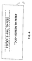
- Figure 4 is a schematic drawing of the display on the central control display when a fault condition is detected;
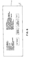
- Figure 5A is a schematic drawing of the display on the central control display when the inserter configuration is displayed;
- Figure 5B is a schematic drawing of the display on the central control display when a selected individual feed station is displayed with the associated switches for modifying its operation; and
- Figure 6 is a schematic drawing of the display on the central control display in the diagnostic mode.
- Referring to Figure 1, a multi-station document inserter is illustrated as 10. A
central control display 12 is electrically connected to theinserter 10. - Advantageously, the
central control display 12 is a finger touch display, such as Fluke Model 1780A InfoTouch Display. Both the multi-station document inserter 10 andcentral control display 12 are of the type disclosed in copending U.S. patent application Serial No. 394 388 filed on 1st July 1982 in the names of Peter N. Piotroski and John M. Gomes, European Patent Application Number (E59/13), entitled UNIVERSAL MULTI-STATION DOCUMENT INSERTER, the disclosure of which is incorporated herein by reference. As disclosed in the aforementioned patent application, thecentral control display 12 is electrically connected to the supervisory control circuit of the multi-station document inserter 10 through a RS232C standard communication line. Thecentral control display 12 provides an operator or user with certain switches which when activated cause theinserter 10 to undergo certain routines and provide displays in human readable form. - Referring to
Fi g. 2, thEcentral control display 12 is shown with certain information displayed upon Power Up. Specifically, the following switches are displayed: - Start Machine - Shall start machine operation.
- One Cycle - Shall activate system operation for one cycle.
- Continuous Run - Shall activate system for continuous-run operation.
- Sequence Start - Shall sequentially activate one feeder module per cycle. Shall activate envelope module feeder in time to insert first collation.
- Stop - Shall allow inserter operation to be stopped. Actual cessation of operation occurs at only one point in inserter cycle.
- Clear Deck (Sequence Stop) - Shall sequentially deactivate one feeder module per cycle. Shall deactivate envelope feeder after last collation is inserted. Shall process last inserted collation throuch postage meter (if applicable) to stacker.
- Chance Set-Up - Shall provide a display of the inserter configuration for change in inserter operation.
- Further, the display shall display information enabling the operator to determine:
- Operating Mode
- Fault Condition (if any)
- Piece Count
- A maintenance reminder message is displayed upon the first power-up after one million cycles. Thereafter, the reminder message is displayed after each subsequent power-up until cancelled by the service technician.
- Referring to Fig. 3, during continous run operation, the following information is displayed on the central control display 12:
- Operating Mode
- Piece Count
- Action To Be Taken To Halt Operation
- Referring to Fig. 4, upon detection of a fault by the supervisory control circuit of the document inserter 10, the following information is displayed on the central control display 12:
- Fault Display - Upon detection of a fault by any of the document or inserter sensors, inserter operation shall be halted (dependent upon specific application requirements) and the following type of information displayed on the central control display 12:
- Fault location,
e.g. station 5 - Fault description, e.g.:
- Jam
- Failure to Feed
- Double
- Mismatch
- Late Feed
- Open Cover
- Referring to Fig. 5A, when the operator actuates the inserter Change Set Up switch of Fig. 2, the following information regarding the configuration of the inserter is displayed on the central control display 12:
- Station Numbers
- Type of Feeder per Station Number
- Feeder Select Status
- Feeder On/Off Status
- Assigned Station Number
- Line Spacing (scan marks at multiple document feeders) '
- Feed Stop
- Feed Count
- Mismatch Count
- Postage Break
- Low Break
- High Break
- Additionally, Reset, Modify, Reassign, Diagnosis and Reset Piece Count switches are displayed. Further, as seen in Fig. 5B, upon display of the foregoing information regarding the configuration of the
inserter 10 the user-operator may reprogram the supervisory control circuit to reconfigure theinserter 10 by actuating the Modify switch and a particular station number for re- display of the foregoing information as well as the following switches: - Status (On/Off) - Shall enable the operator to deactivate a designated feeder module.
- Feed Count - Shall enable the operator to set a maximum document count or a specified number of documents.
- Feed Stop - Shall enable the operator to set the document count or the control document to set the count.
- Postage Break Low and Postage Break High - Shall enable the operator to set two limits associated with a predetermined count from a designated multiple document feeder.
- Mismatch Count - Shall enable the operator to specify the maximum consecutive number of mismatches allowed.
- Line Spacing - Shall enable the operator to specify the line spacing for dash mark scanning.
- Reset Values - Shall enable the operator to reset to the original configuration of the inserter.
- Exit - Shall enable the operator to leave a particular document feeder display and display the entire inserter configuration as in Fig. 5A.
- Referring to
Fi g. 6, upon selection of the proper access code the following information shall be displayed on thecentral control display 12 during thediagnostic mode to enable the service technician to individually activate input or output devices and/or mechanisms for testing, as follows: - Fault Lights
- Brakes
- Clutches
- Solenoids
- Motors
- Photocells
- .Interlocks
- Sensors
- Switches
- The supervisory control circuit of the
inserter 10 under control of the program in the Microfiche Appendix provides the aforementioned displays of operating functions and switches on thecentral control display 12 for interaction with the inserter user-operator. - It should be apparent to those skilled in the art that various modifications may be made in present invention without departing from scope thereof as described in specification and defined in the appended claims.
- It will be seen that there has been particularly disclosed and illustrated herein:
- a central control display capable of displaying fault locations and describing the type of faults encountered in a multi-station document inserter;
- a user-interactive central control display for a multi-station inserter for displaying information in human readable form;
- a central control which displays the operating conditions of a multi- station document inserter; and which includes a maintenance reminder.
Claims (18)
Applications Claiming Priority (2)
| Application Number | Priority Date | Filing Date | Title |
|---|---|---|---|
| US39438682A | 1982-07-01 | 1982-07-01 | |
| US394386 | 1999-09-10 |
Publications (2)
| Publication Number | Publication Date |
|---|---|
| EP0102700A2 true EP0102700A2 (en) | 1984-03-14 |
| EP0102700A3 EP0102700A3 (en) | 1985-08-07 |
Family
ID=23558751
Family Applications (1)
| Application Number | Title | Priority Date | Filing Date |
|---|---|---|---|
| EP83303767A Withdrawn EP0102700A3 (en) | 1982-07-01 | 1983-06-29 | User friendly central control display for a multi-station document inserter |
Country Status (1)
| Country | Link |
|---|---|
| EP (1) | EP0102700A3 (en) |
Cited By (14)
| Publication number | Priority date | Publication date | Assignee | Title |
|---|---|---|---|---|
| EP0180386A2 (en) * | 1984-10-29 | 1986-05-07 | Pitney Bowes, Inc. | Inserter system with interactive system |
| EP0258495A2 (en) * | 1986-03-10 | 1988-03-09 | Bell & Howell Company | Insertion machine with audit trail and command protocol |
| EP0376467A1 (en) * | 1988-12-30 | 1990-07-04 | Pitney Bowes, Inc. | Method and apparatus for remotely controlling a document inserter |
| EP0392867A1 (en) * | 1989-04-14 | 1990-10-17 | BELL & HOWELL PHILLIPSBURG COMPANY | In-line rotary inserter |
| US5029832A (en) * | 1989-04-14 | 1991-07-09 | Bell & Howell Phillipsburg Co. | In-line rotary inserter |
| US5125642A (en) * | 1989-04-14 | 1992-06-30 | Bell & Howell Company | Feeder module with thickness detection |
| US5125215A (en) * | 1989-04-14 | 1992-06-30 | Bell & Howell Phillipsburg Co. | Envelope flap opener |
| US5125214A (en) * | 1989-04-14 | 1992-06-30 | Bell & Howell Company | Inserter station for envelope inserting |
| US5127640A (en) * | 1989-04-14 | 1992-07-07 | Bell & Howell Phillipsburg Co. | Inserter with collation tracking |
| US5130558A (en) * | 1989-04-14 | 1992-07-14 | Bell & Howell Company | Skew detector for inserter |
| US5129503A (en) * | 1989-04-14 | 1992-07-14 | Bell & Howell Company | Turnover module |
| US5154404A (en) * | 1989-04-14 | 1992-10-13 | Bell & Howell Phillipsburg Company | Jam detector for inserter |
| US5201504A (en) * | 1988-08-26 | 1993-04-13 | Bell & Howell Company | On-edge stacker |
| NL9401155A (en) * | 1994-07-12 | 1996-02-01 | Hadewe Bv | Mail processing system with diagnostic facilities. |
Citations (4)
| Publication number | Priority date | Publication date | Assignee | Title |
|---|---|---|---|---|
| US3606728A (en) * | 1969-09-08 | 1971-09-21 | Bell & Howell Co | Insertion machine |
| US3905594A (en) * | 1973-04-16 | 1975-09-16 | Norfin | Memory and visual indicator system for sorting device |
| US3935429A (en) * | 1975-02-18 | 1976-01-27 | Pitney-Bowes, Inc. | Process and apparatus for controlling document feeding machines from indicia contained on a document fed therefrom |
| US4133477A (en) * | 1976-04-15 | 1979-01-09 | Xerox Corporation | Fault detection and system for electrostatographic machines |
-
1983
- 1983-06-29 EP EP83303767A patent/EP0102700A3/en not_active Withdrawn
Patent Citations (4)
| Publication number | Priority date | Publication date | Assignee | Title |
|---|---|---|---|---|
| US3606728A (en) * | 1969-09-08 | 1971-09-21 | Bell & Howell Co | Insertion machine |
| US3905594A (en) * | 1973-04-16 | 1975-09-16 | Norfin | Memory and visual indicator system for sorting device |
| US3935429A (en) * | 1975-02-18 | 1976-01-27 | Pitney-Bowes, Inc. | Process and apparatus for controlling document feeding machines from indicia contained on a document fed therefrom |
| US4133477A (en) * | 1976-04-15 | 1979-01-09 | Xerox Corporation | Fault detection and system for electrostatographic machines |
Non-Patent Citations (1)
| Title |
|---|
| IBM TECHNICAL DISCLOSURE BULLETIN, vol. 24, no. 7A, December 1981, pages 3295-3297, Armonk, N.Y., US; J.H. DODGE et al.: "Self-analysis of copier electronics" * |
Cited By (19)
| Publication number | Priority date | Publication date | Assignee | Title |
|---|---|---|---|---|
| EP0180386A2 (en) * | 1984-10-29 | 1986-05-07 | Pitney Bowes, Inc. | Inserter system with interactive system |
| EP0180386A3 (en) * | 1984-10-29 | 1988-03-02 | Pitney Bowes, Inc. | Inserter system with interactive system |
| EP0258495A2 (en) * | 1986-03-10 | 1988-03-09 | Bell & Howell Company | Insertion machine with audit trail and command protocol |
| EP0258495A3 (en) * | 1986-03-10 | 1989-10-25 | Bell & Howell Company | Insertion machine with audit trail and command protocol |
| US5201504A (en) * | 1988-08-26 | 1993-04-13 | Bell & Howell Company | On-edge stacker |
| EP0376467A1 (en) * | 1988-12-30 | 1990-07-04 | Pitney Bowes, Inc. | Method and apparatus for remotely controlling a document inserter |
| US5125642A (en) * | 1989-04-14 | 1992-06-30 | Bell & Howell Company | Feeder module with thickness detection |
| US5042232A (en) * | 1989-04-14 | 1991-08-27 | Bell & Howell Phillipsburg Co. | In-line rotary inserter |
| US5029832A (en) * | 1989-04-14 | 1991-07-09 | Bell & Howell Phillipsburg Co. | In-line rotary inserter |
| US5125215A (en) * | 1989-04-14 | 1992-06-30 | Bell & Howell Phillipsburg Co. | Envelope flap opener |
| US5125214A (en) * | 1989-04-14 | 1992-06-30 | Bell & Howell Company | Inserter station for envelope inserting |
| US5127640A (en) * | 1989-04-14 | 1992-07-07 | Bell & Howell Phillipsburg Co. | Inserter with collation tracking |
| US5130558A (en) * | 1989-04-14 | 1992-07-14 | Bell & Howell Company | Skew detector for inserter |
| US5129503A (en) * | 1989-04-14 | 1992-07-14 | Bell & Howell Company | Turnover module |
| US5154404A (en) * | 1989-04-14 | 1992-10-13 | Bell & Howell Phillipsburg Company | Jam detector for inserter |
| EP0392867A1 (en) * | 1989-04-14 | 1990-10-17 | BELL & HOWELL PHILLIPSBURG COMPANY | In-line rotary inserter |
| NL9401155A (en) * | 1994-07-12 | 1996-02-01 | Hadewe Bv | Mail processing system with diagnostic facilities. |
| EP0697259A1 (en) * | 1994-07-12 | 1996-02-21 | Hadewe B.V. | Mail processing system with diagnostic facilities |
| US5984507A (en) * | 1994-07-12 | 1999-11-16 | Hadewe B. V. | Mail processing system with diagnostic facilities |
Also Published As
| Publication number | Publication date |
|---|---|
| EP0102700A3 (en) | 1985-08-07 |
Similar Documents
| Publication | Publication Date | Title |
|---|---|---|
| EP0102700A2 (en) | User friendly central control display for a multi-station document inserter | |
| US4547856A (en) | Universal multi-station document inserter | |
| EP0376467B1 (en) | Method and apparatus for remotely controlling a document inserter | |
| US4525788A (en) | Scanner interface circuit for universal multi-station document inserter | |
| US4517650A (en) | Feeder interface circuit for universal multi-station document inserter | |
| US4639889A (en) | System for controlling communication between a main control assembly and programmable terminal units | |
| DE10020074A1 (en) | Modular safety switchgear system | |
| CH668875A5 (en) | TRANSMITTER AND RECEIVER AND COMMUNICATION DEVICE WITH TRANSMITTER AND RECEIVER. | |
| CA2006024A1 (en) | Dual mode communication | |
| AU630905B2 (en) | Auto-translation system for generating messages in a modular machine | |
| EP0057987A1 (en) | Display device for photocopiers | |
| CA2006018C (en) | Asynchronous rejection in an inserter | |
| US5321602A (en) | Tutorial control panel | |
| JPH02289400A (en) | Start-up procedure of multimaterial treatment system | |
| US3458383A (en) | Mailing piece separator | |
| US2799846A (en) | Fault indicating system | |
| EP0102704A2 (en) | Multi-station document inserter with automatic startup and shutdown document collation sequences | |
| US2265439A (en) | Sorting machine for perforated records | |
| US2234272A (en) | Testing circuit | |
| DE1204703B (en) | Device for monitoring the transmission of data according to the counting method | |
| US2738131A (en) | Record controlled counting circuits | |
| US2673235A (en) | Telegraph message allotting system | |
| JP2884802B2 (en) | Remote monitoring and control device | |
| US3179742A (en) | Automatic message identification circuit for telegraph machines | |
| JPS63143985A (en) | Operation indicator |
Legal Events
| Date | Code | Title | Description |
|---|---|---|---|
| PUAI | Public reference made under article 153(3) epc to a published international application that has entered the european phase |
Free format text: ORIGINAL CODE: 0009012 |
|
| AK | Designated contracting states |
Designated state(s): CH DE FR GB LI |
|
| PUAL | Search report despatched |
Free format text: ORIGINAL CODE: 0009013 |
|
| AK | Designated contracting states |
Designated state(s): CH DE FR GB LI |
|
| 17P | Request for examination filed |
Effective date: 19860123 |
|
| 17Q | First examination report despatched |
Effective date: 19870323 |
|
| D17Q | First examination report despatched (deleted) | ||
| STAA | Information on the status of an ep patent application or granted ep patent |
Free format text: STATUS: THE APPLICATION IS DEEMED TO BE WITHDRAWN |
|
| 18D | Application deemed to be withdrawn |
Effective date: 19880708 |
|
| RIN1 | Information on inventor provided before grant (corrected) |
Inventor name: PIOTROSKI, PETER N. Inventor name: GOMES, JOHN M. |