EP0103192A2 - Glass brick, wall of glass building elements and method of laying and erecting the same - Google Patents
Glass brick, wall of glass building elements and method of laying and erecting the same Download PDFInfo
- Publication number
- EP0103192A2 EP0103192A2 EP83108034A EP83108034A EP0103192A2 EP 0103192 A2 EP0103192 A2 EP 0103192A2 EP 83108034 A EP83108034 A EP 83108034A EP 83108034 A EP83108034 A EP 83108034A EP 0103192 A2 EP0103192 A2 EP 0103192A2
- Authority
- EP
- European Patent Office
- Prior art keywords
- glass
- projections
- frame
- component according
- glass blocks
- Prior art date
- Legal status (The legal status is an assumption and is not a legal conclusion. Google has not performed a legal analysis and makes no representation as to the accuracy of the status listed.)
- Granted
Links
Images


Classifications
-
- E—FIXED CONSTRUCTIONS
- E04—BUILDING
- E04C—STRUCTURAL ELEMENTS; BUILDING MATERIALS
- E04C1/00—Building elements of block or other shape for the construction of parts of buildings
- E04C1/42—Building elements of block or other shape for the construction of parts of buildings of glass or other transparent material
Definitions
- the invention relates to a glass block with a dimensionally accurate frame made of plastic, which is provided on its circumferential surfaces with projections and depressions for fitting the glass blocks.
- Glass blocks of this type are known in which the dimensionally accurate frame is provided with tongue-and-groove recesses or projections which interlock when a wall part is constructed from such glass blocks and serve as a centering means (DE-AS 22 63 127).
- the frame can also be designed so that it is provided with lateral projections that extend to the glass edge of an adjacent glass block, while the frame of the adjacent glass block ends set back by the amount of these projections.
- the well-known framed glass blocks are glued together on their abutting surfaces with the interposition of an adhesive.
- the interlocking projections and recesses do not give each other the glass blocks with which they interact, but only prevent mutual displacement in one direction. Until the adhesive has set, there is a mutual displacement of the glass blocks in the other two directions possible, which can no longer be corrected after the adhesive has set.
- the invention has for its object to develop a glass block of the type mentioned in such a way that the construction of a wall part from such glass blocks is further simplified and facilitated.
- the frame should be designed so that the glass components can be connected to one another to form a firmly holding wall without the interposition of an adhesive layer.
- the butt joints of the abutting glass components should be sealed against the ingress of water, so that a wall constructed from such glass components is suitable for the creation of external walls both in terms of their mechanical strength and their tightness to moisture.
- this object is achieved in that the peripheral surfaces of the frame are provided on the one hand with three-dimensional projections and recesses which define the mutual position of the components in two spatial directions and enable a fixed plug connection, and on the other hand along the narrow sides with load-bearing frame-shaped projections, and that
- the frame consists of a plastic with a closed surface and a Shore D hardness of 7o to 85.
- the actual glass body 1 of the glass block consists of two half-stones 1a and 1b (FIG. 2) which are welded together to form a weld seam 2.
- glass blocks produced by other processes can of course also be provided with the frame 3 according to the invention. It may even be possible to use two half-stones not yet connected to one another instead of a complete glass block, and to provide them in the correct position with respect to one another with the frame, which in this case also has the task, in addition to the function according to the invention, for the fixed ones To ensure connection and sealing of the assembled glass block.
- the frame 3 is arranged as a closed, dimensionally accurate frame on the entire peripheral surface of the glass body 1.
- the outer dimensions of the frame 3 have narrow dimensional tolerances, so that the surfaces which interact with one another lie tightly against one another, and the connecting projections or recesses ensure a firm fit after being plugged together.
- the frame 3 is produced, for example, in a manner known per se according to the so-called “reaction foam casting process”, which is also known as the RIM process (reaction injection molding).
- reaction foam casting process which is also known as the RIM process (reaction injection molding).
- the plastic in liquid form is sprayed onto the peripheral surface of the glass body 1 within a correspondingly designed molding tool.
- the plastic hardens in the mold, so that the framed glass block is removed from the mold.
- adhesion promoters In order to increase the adhesion of the plastic to the glass surface, it is possible to use adhesion promoters or “primers” which are matched to the respective plastic and which are applied to the peripheral surface of the glass body before the glass body is inserted into the mold.
- adhesion promoters are commercially available and are selected in accordance with the plastic used for the framing.
- the peripheral surface 4 can be roughened or provided with a structure such that the surface in contact with the plastic of the frame is substantially larger than in the smooth state.
- This ge Desired enlargement of the glass surface is achieved by appropriate design of the mold walls of the molds with which the half stones 1-a, 1b are pressed.
- a sufficient enlargement of the glass surface can be achieved by corrugation, corrugation or other roughening of the wall of the mold.
- the outer circumferential surface of the framing 3 is assembled in which in example of FIG. 1 and 2 consists of a central plane surface 5, the excellent from this area 5 connecting projections 1 0, the protruding into the framing connecting recesses 12, the narrow sides 13 and along the the narrow sides 13 arranged, protruding from the surface 5 strip-like supporting projections 7. These projections 7 form the actual force-transmitting contact surfaces between the individual glass blocks.
- the projections 7 are separated from one another by a groove-shaped depression 8 .
- Each upper flat boundary surface of the projections 7 has a width B of approximately 2 to 4 mm
- the groove-shaped recess 8 has a width b of 1 to 3 mm, preferably of approximately 2 mm.
- This design of the projections 7 in connection with the elastic deformability of the plastic forming the frame creates a seal with favorable sealing properties.
- the groove-shaped recesses 8 of the glass blocks arranged next to one another in a wall part constructed from these glass blocks are connected to one another, and the perpendicular groove-shaped recesses 8 form, as it were, groove-like cavities through which water which has possibly penetrated through the first sealing surface can run off.
- connection projections 1o have the shape of circular cylinders. Their diameter d amounts to a total thickness D of the glass block of 80 mm-approximately 40 mm.
- the hollow cylindrical depressions 12 have corresponding dimensions.
- the sealing projections 7 have a height H of, for example, 0.6 mm. When the glass blocks are joined together, this creates a cavity with a height of 1.2 mm between the flat boundary surfaces 5. This cavity serves for the insertion of reinforcing tapes 14.
- the reinforcing tapes 14 have holes 15 punched at the intervals specified by the projections 10 or depressions 12, and consist of a 1 mm thick metal tape.
- the reinforcement tapes 14 can be made of a suitable metal, such as Aluminum for low structural requirements, or stainless steel for very high structural requirements.
- the frame 3 consists of an integral foam, that is, a plastic with an unfoamed cover layer and a foamed core.
- a hard integral polyurethane foam with a molded foam density of 4oo to 7oo kg / m 3 , a flexural modulus according to DIN 53 423 from 95o to 11oo MPa is particularly suitable, a compressive strength according to DIN 53 421 with 1o% compression from 1o to 18 MPa, a Shore D hardness according to DIN 53 5 0 5 from 7o to 85, and a linear thermal expansion coefficient according to DIN 53 122 of ⁇ loo m / mK10 6 , each at a bulk density of 6 00 kg / m 3 .
- this cover layer plays a decisive role in these integral foams.
- this cover layer also has a significantly higher modulus of elasticity than the integral material.
- the modulus of elasticity of the cover layer can assume values up to 2ooo MPa.
- the conditions referred fulfilled in a satisfactory manner for example, the integral skin foam of the Fa. Bayer with the trade name BAYDUR 651o F.
- This material has kg at a density of 6 00 / m 3, a flexural E-modulus of 1o5o MPa, a compressive strength of 12 MPa, a Shore D hardness of 79, and a linear thermal expansion coefficient of 9o m / mK10 6 .
- a liquid blowing agent is added to the two polyol and isocyanate components which react to form the polyurethane, as a result of which the polyurethane formed during the reaction of the components foams.
- thermoplastic plastics are also suitable for the frame, insofar as their material properties, in particular their compressive strength and their elastic properties, are comparable with those of the integral foams mentioned.
- the protrusions 1 0 and the recesses can be mounted in principle 12 for the plug connectors in any arrangement.
- two opposite sides with projections lo, and the other two against each other overlying sides may be provided with depressions 12.
- two adjacent sides can also be provided with projections and depressions, or, as in the exemplary embodiments shown, alternately one projection 10 and one depression 12 can be provided on each side of the peripheral surface.
- recesses 16, 17, 18 are provided in the frame 3 at the points which are of no importance for the actual functions of the frame 3 with regard to the static properties and the tightness of a wall part composed of such glass blocks.
- the amount of plastic material of the frame 3 is significantly reduced, which brings with it a cost advantage, which is particularly significant when the plastic used is relatively expensive.
- the frame 3 of the glass block can also, as shown in the exemplary embodiment according to FIG. 4, be provided in the middle with longitudinal grooves 19, 19 'which extend to the bottom of the recesses 16, 17, 18. These longitudinal grooves 19, 19 'are used to insert a tension wire 2 0 , for example made of high-strength stainless steel.
- connection of the glass blocks with the aid of such tensioning wires is particularly suitable for those cases in which the glass blocks are not assembled to flat wall surfaces, but instead, for example, to cylindrical wall surfaces.
- only the peripheral surfaces of the frame need to be formed on one or more sides with the desired inclination, so that two adjoining stones form an angle different from 180 degrees.
- This method of mutual prestressing with the help of a tension wire also has the advantage that the required contact forces are generated exclusively in the wall part itself, without the adjacent structural parts being thereby put under tension.
- FIG. 5-sectional view of one recognizes the tension wire 2 0 within the longitudinal groove 19th
- this illustration shows a possibility of how there are particularly high demands on the watertightness of one of the glass blocks according to the invention an additional seal can be achieved on the wall.
- An injection-capable, permanently elastic sealing compound 27, for example based on silicone is injected under pressure through these bores 26 with the aid of a suitable spraying device provided with a cannula that can be inserted into the bore 26.
- the sealing compound 27 flows under the effect of the pressure through the longitudinal groove 8 'and thus ensures a reliable additional seal.
- these additional sealing measures are only carried out on the side of the wall part which is affected by the moisture or the water.
- the width b ' is advantageously approximately 3 mm and the height H' approximately 1.5 mm.
- the fastening projections arranged on the circumferential surfaces 5 have the shape of annular hollow cylinders 32.
- the inner wall surface 33 is slightly conical in that the diameter increases somewhat towards the outside.
- the outer wall surface 34 has a cylindrical shape.
- the hollow cylinders are in four Segments divided, which gives them the required elasticity.
- the fillet 36 at the foot of the hollow cylinder 32 also contributes to increasing the elasticity.
- the depression provided for receiving this hollow cylinder 32 in the frame of the adjacent glass block accordingly has the shape of an annular channel 38.
- the outer boundary surface 39 of the annular channel is cylindrical.
- the inner boundary surface 40 of the annular channel 38 has a slightly conical shape and forms the outer surface of a conical body 41. This cone 41 serves as an expanding cone for the segments of the hollow cylinder 32.
- the glass blocks are joined together using hammer blows.
- the segments of the hollow cylinder 32 are pressed apart by the expansion cone 41.
- the spreading reaches its greatest extent at the edge of the hollow cylinder 32.
- the hollow cylinder wall is anchored to a certain extent in the wall 39 of the ring channel near the base surface 42 of the ring channel 38, so that the force is introduced into the frame 3 at the most favorable point for reasons of strength becomes.
- the taper of the cone 41 and the hollow cone surface 33 of the sleeve 32 is relatively low. Good results are achieved if the angle of inclination of the surface lines of the cone 41 is four to eight degrees, and preferably about five degrees. Under these conditions, the connection is self-locking after assembly, so that unwanted loosening of the connection cannot occur.
- the cone 41 within the ring channel 38 can in turn also be designed as a hollow cone, in that it is merely designed as a ring. This saves material, on the one hand, and on the other hand, this cone can be given a certain elasticity, which can be advantageous with regard to possible manufacturing tolerances.
- FIG. 8 Another method for further increasing the cohesion or the strength of a wall part composed of glass blocks according to the invention is shown in FIG. 8.
- perforated strips 44 are clamped onto the narrow sides of the wall part.
- the perforated strips 44 can be made of metal or plastic and can be cut to the required length at the construction site.
- the perforated strips 44 are pushed onto the projections 10. Insofar as the glass blocks on this side do not have projections, but depressions 12, 12 connecting plugs 45 are inserted into these depressions, which take over the role of the projections at these points.
- a perforated strip 44 'of a length corresponding to the width of the wall part is first fastened to the concrete or masonry base 46, for example with the aid of dowels.
- cylindrical connecting plugs 45 are inserted into the recesses on the underside of the lowermost glass building blocks, and the bottom row of the glass building blocks are fastened to the perforated strip 44 'with the connecting projections 10 or the connecting plugs 45'.
- the wall part is put together in the desired size, will also be on the lateral and on the upper boundary surface of the wall part in the recesses of the frame connecting plug 45, and then pushed perforated strips 44 over the connecting projections 10 or connecting plug 45.
- the joints remaining up to the opening of the wall are then closed in the usual way, for example by mortar or by spraying with a plastic or plastic foam.
Abstract
Ein Glasbaustein ist mit einer maßgenauen Umrahmung aus einem Integral-Schaumstoff versehen, wobei die Umrahmung (3) auf den Stoßflächen mit Vorsprüngen (10) und Ausnehmungen (12) versehen ist, die eine feste Steckverbindung ermöglichen. Entlang den Schmalseiten (13) weist die Umrahmung (3) Dichtvorsprünge (7) auf. Der Raum zwischen den Dichtvorsprüngen (7) dient für die Einlage von Bewehrungsstäben aus Flachprofilen, die mit Durchtrittsöffnungen für die Steckvorsprünge (10) versehen sind. Das Verlegen der Glasbausteine erfolgt ohne zusätzliche Klebemittel, so daß aus solchen Glasbausteinen aufgebaute Wände oder Wandteile demontiert werden können und die Glasbausteine wiederverwendbar sind.A glass block is provided with a dimensionally accurate frame made of an integral foam, the frame (3) being provided with projections (10) and recesses (12) on the abutting surfaces, which enable a firm plug connection. The frame (3) has sealing projections (7) along the narrow sides (13). The space between the sealing projections (7) is used for the insertion of reinforcing bars made of flat profiles, which are provided with openings for the plug-in projections (10). The glass blocks are laid without additional adhesives, so that walls or wall parts built up from such glass blocks can be dismantled and the glass blocks can be reused.
Description
Die Erfindung betrifft einen Glasbaustein mit einer maßgenauen Umrahmung aus Kunststoff, die auf ihren Umfangsflächen mit Vorsprüngen und Vertiefungen zum paßgerechten Verlegen der Glasbausteine versehen ist.The invention relates to a glass block with a dimensionally accurate frame made of plastic, which is provided on its circumferential surfaces with projections and depressions for fitting the glass blocks.
Es sind Glasbausteine dieser Art bekannt, bei denen die maßgenaue Umrahmung mit nut- und federartigen Aussparungen bzw. Vorsprüngen versehen ist, die beim Aufbau eines Wandteils aus solchen Glasbausteinen ineinandergreifen und als Zentriermittel dienen (DE-AS 22 63 127). Die Umrahmung kann dabei auch so ausgebildet sein, daß sie mit seitlichen Vorsprüngen versehen ist, die bis auf den Glasrand eines anliegenden Glasbausteins reichen, während die Umrahmung des anliegenden Glasbausteins um das Maß dieser Vorsprünge vom Rand zurückversetzt endet.Glass blocks of this type are known in which the dimensionally accurate frame is provided with tongue-and-groove recesses or projections which interlock when a wall part is constructed from such glass blocks and serve as a centering means (DE-AS 22 63 127). The frame can also be designed so that it is provided with lateral projections that extend to the glass edge of an adjacent glass block, while the frame of the adjacent glass block ends set back by the amount of these projections.
Die bekannten umrahmten Glasbausteine werden an ihren Stoßflächen unter Zwischenschaltung eines Klebers miteinander verklebt. Die ineinandergreifenden Vorsprünge und Vertiefungen geben den Glasbausteinen, mit denen sie zusammenwirken, keinen gegenseitigen Halt, sondern verhindern lediglich das gegenseitige Verschieben in einer Richtung. Bis zum Abbinden des Klebers ist also eine gegenseitige Verschiebung der Glasbausteine in den beiden anderen Richtungen möglich, die nach dem Abbinden des Klebers nicht mehr korrigiert werden kann.The well-known framed glass blocks are glued together on their abutting surfaces with the interposition of an adhesive. The interlocking projections and recesses do not give each other the glass blocks with which they interact, but only prevent mutual displacement in one direction. Until the adhesive has set, there is a mutual displacement of the glass blocks in the other two directions possible, which can no longer be corrected after the adhesive has set.
Der Erfindung liegt die Aufgabe zugrunde, einen Glasbaustein der eingangs genannten Art so weiterzubilden, daß der Aufbau eines Wandteils aus solchen Glasbausteinen weiter vereinfacht und erleichtert wird. Dabei soll insbesondere die Umrahmung so ausgebildet sein, daß die Glasbauelemente ohne Zwischenschaltung einer Klebeschicht zu einer fest zusammenhaltenden Wand miteinander verbunden werden können. Die Stoßfugen der aneinanderstoßenden Glasbauelemente sollen dabei gegen eindringendes Wasser dicht sein, so daß eine aus derartigen Glasbauelementen aufgebaute Wand sich sowohl hinsichtlich ihrer mechanischen-Belastbarkeit wie bezüglich ihrer Dichtigkeit gegenüber Feuchtigkeit auch für die Erstellung von Außenwänden eignet.The invention has for its object to develop a glass block of the type mentioned in such a way that the construction of a wall part from such glass blocks is further simplified and facilitated. In particular, the frame should be designed so that the glass components can be connected to one another to form a firmly holding wall without the interposition of an adhesive layer. The butt joints of the abutting glass components should be sealed against the ingress of water, so that a wall constructed from such glass components is suitable for the creation of external walls both in terms of their mechanical strength and their tightness to moisture.
Erfindungsgemäß wird diese Aufgabe dadurch gelöst, daß die Umfangsflächen der Umrahmung einerseits mit dreidimensionalen, die gegenseitige Lage der Bauelemente in zwei räumlichen Richtungen festlegenden, eine feste Steckverbindung ermöglichenden Vorsprüngen und Ausnehmungen, und andererseits entlang den Schmalseiten mit tragenden rahmenförmigen Vorsprüngen versehen sind, und daß die Umrahmung aus einem Kunststoff mit geschlossener Oberfläche und einer Shore-D-Härte von 7o bis 85 besteht.According to the invention, this object is achieved in that the peripheral surfaces of the frame are provided on the one hand with three-dimensional projections and recesses which define the mutual position of the components in two spatial directions and enable a fixed plug connection, and on the other hand along the narrow sides with load-bearing frame-shaped projections, and that The frame consists of a plastic with a closed surface and a Shore D hardness of 7o to 85.
Durch die erfindungsgemäße geometrische Gestaltung der Umfangsflächen, verbunden mit den besonderen Werkstoffeigenschaften des Materials der Umrahmung, erfolgt eine gezielte geringfügige elastische Deformation der Umrahmung im Bereich der gegeneinander anliegenden und die Druckbelastung übernehmenden rahmenartigen Vorsprünge, die für eine sichere Abdichtung der Stoßfugen gegen eindringendes Wasser sorgt. Dadurch wird der Verzicht auf Klebeschichten ermöglicht, und sowohl die feste Verbindung der Elemente untereinander als auch die dauerhafte Abdichtung gegen eindringendes Wasser durch die Gestaltung und Materialauswahl der Umrahmung gewährleistet. Das bedeutet nicht nur eine wesentliche Vereinfachung beim Verlegen, d.h. beim Aufbau eines Wandteils, sondern hat auch zur Folge, daß die Wandteile später jederzeit wieder demontiert, und die Glasbausteine für den Aufbau eines anderen Wandteils ohne weiteres wieder verwendet werden können.The geometrical design of the circumferential surfaces according to the invention, combined with the special material properties of the material of the frame, results in a deliberate slight elastic deformation of the frame in the area of the mutually adjacent and the Frame-like projections that take on pressure loads and ensure that the butt joints are securely sealed against the ingress of water. This makes it possible to dispense with adhesive layers and ensures both the firm connection of the elements to one another and the permanent sealing against ingress of water through the design and material selection of the frame. This not only means a significant simplification when laying, ie when building a wall part, but also has the consequence that the wall parts can be dismantled at any time later, and the glass blocks can easily be used again for the construction of another wall part.
Weitere Einzelheiten und Vorteile der Erfindung ergeben sich aus den Unteransprüchen und aus der nachfolgenden Beschreibung verschiedener Ausführungsbeispiele anhand der Zeichnungen.Further details and advantages of the invention emerge from the subclaims and from the following description of various exemplary embodiments with reference to the drawings.
Von den Zeichnungen zeigt
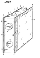
- Fig. 1 eine erste Ausführungsform eines erfindungsgemäß ausgebildeten Glasbausteins in einer perspektivischen Gesamtansicht;
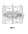
- Fig. 2 eine Schnittdarstellung im Bereich der miteinander zusammenwirkenden Verbindungselemente zweier Glasbausteine nach Fig. 1;
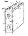
- Fig. 3 eine zweite Ausführungsform eines erfindungsgemäßen Glasbausteins in perspektivischer Darstellung;
- Fig. 4 eine weitere Ausführungsform eines erfindungsgemäßen Glasbausteins, ebenfalls in perspektivischer Darstellung;
- Fig. 5 eine Schnittdarstellung entlang der Linie V-V in Fig. 4 im Übergangsbereich zweier zusammengesetzter Glasbausteine;
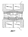
- Fig. 6 eine weitere Ausführungsform eines erfindungsgemäßen Glasbausteins in perspektivischer Darstellung;
- Fig. 7 eine Schnittdarstellung entlang der Linie VII-VII in Fig.6 im Obergangsbereich zweier zusammenwirkender Glasbausteine, und
- Fig. 8 einen erfindungsgemäß aufgebauten Wandteil.
- Figure 1 shows a first embodiment of a glass block designed according to the invention in an overall perspective view.
- FIG. 2 shows a sectional illustration in the region of the interconnecting connecting elements of two glass blocks according to FIG. 1;
- 3 shows a second embodiment of a glass block according to the invention in a perspective view;
- 4 shows a further embodiment of a glass block according to the invention, likewise in a perspective view;
- FIG. 5 shows a sectional illustration along the line VV in FIG. 4 in the transition region of two assembled glass blocks;
- 6 shows a further embodiment of a glass block according to the invention in a perspective view;
- Fig. 7 is a sectional view taken along the line VII-VII in Fig.6 in the transition area of two interacting glass blocks, and
- 8 shows a wall part constructed according to the invention.
Der eigentliche Glaskörper 1 des Glasbausteins besteht aus zwei Halbsteinen 1a und 1b (Fig. 2), die unter Bildung einer Schweißnaht 2 miteinander verschweißt sind. Anstelle von geschweißten Glasbausteinen können selbstverständlich auch nach anderen Verfahren hergestellte Glasbausteine mit der erfindungsgemäßen Umrahmung 3 versehen sein. Es ist unter Umständen sogar möglich, statt eines vollständigen Glasbausteins zwei noch nicht miteinander verbundene Halbsteine zu verwenden, und diese in der richtigen Position zueinander mit der Umrahmung zu versehen, die in diesem Fall außer der erfindungsgemäßen Funktion auch noch die Aufgabe hat, für die feste Verbindung und die Abdichtung des zusammengesetzten Glasbausteins zu sorgen.The
Die Umrahmung 3 ist als geschlossener maßgenauer Rahmen auf der gesamten Umfangsfläche des Glaskörpers 1 angeordnet. Die Außenabmessungen der Umrahmung 3 haben enge Maßtoleranzen, so daß die miteinander zusammenwirkenden Flächen sich dicht gegeneinander legen, und die Verbindungsvorsprünge bzw. -vertiefungen nach dem Zusammenstecken einen festen Sitz gewährleisten.The
Die Herstellung der Umrahmung 3 erfolgt beispielsweise in an sich bekannter Weise nach dem sogenannten "Reaktions-Schaum-Gießverfahren", das auch als RIM-Verfahren (Reaction-Injection-Molding) bekannt ist. Dabei wird der Kunststoff in flüssiger Form innerhalb eines entsprechend gestalteten Formwerkzeugs auf die Umfangsfläche des Glaskörpers 1 aufgespritzt. Der Kunststoff härtet in dem Formwerkzeug aus, so daß dem Formwerkzeug der fertig umrahmte Glasbaustein entnommen wird.The
Zur Erhöhung der Haftung des Kunststoffs an der Glasoberfläche kann man auf den jeweiligen Kunststoff abgestimmte Haftverbesserer oder "Primer" anwenden, die vor dem Einlegen des Glaskörpers in das Formwerkzeug auf die Umfangsfläche des Glaskörpers aufgebracht werden. Solche Haftverbesserer sind handelsüblich und werden entsprechend dem für die Umrahmung verwendeten Kunststoff ausgewählt.In order to increase the adhesion of the plastic to the glass surface, it is possible to use adhesion promoters or “primers” which are matched to the respective plastic and which are applied to the peripheral surface of the glass body before the glass body is inserted into the mold. Such adhesion promoters are commercially available and are selected in accordance with the plastic used for the framing.
Zur weiteren Haftverbesserung der Umrahmung 3 auf dem Glaskörper 1 kann man die Umfangsfläche 4 derart aufrauhen bzw. mit einer Struktur versehen, daß die mit dem Kunststoff der Umrahmung in Kontakt stehende Oberfläche wesentlich größer ist als im glatten Zustand. Diese gewünschte Vergrößerung der Glasoberfläche wird durch entsprechende Gestaltung der Formwände der Preßformen erreicht, mit denen die Halbsteine 1-a, 1b gepreßt werden. Eine ausreichende Vergrößerung der Glasoberfläche läßt sich durch eine Riffelung, Nörpelung oder sonstige Aufrauhung der Wand der Preßform erreichen.To further improve the adhesion of the
Die äußere Umfangsfläche der Umrahmung 3 setzt sich bei dem in Fig. 1 und 2 dargestellten Beispiel zusammen aus einer zentralen ebenen Fläche 5, den aus dieser Fläche 5 hervorragenden Verbindungsvorsprüngen 10, den in die Umrahmung hineinragenden Verbindungsausnehmungen 12, den Schmalseiten 13 und den entlang den Schmalseiten 13 angeordneten, aus der Fläche 5 herausragenden leistenartigen tragenden Vorsprüngen 7. Diese Vorsprünge 7 bilden die eigentlichen kraftübertragenden Kontaktflächen zwischen den einzelnen Glasbausteinen.The outer circumferential surface of the
Die Vorsprünge 7 sind durch eine nutförmige Vertiefung 8 voneinander getrennt. Jede obere ebene Begrenzungsfläche der Vorsprünge 7 hat eine Breite B von etwa 2 bis 4 mm, und die nutförmige Vertiefung 8 hat eine Breite b von 1 bis 3 mm, vorzugsweise von etwa 2 mm. Durch diese Gestaltung der Vorsprünge 7 wird in Verbindung mit der elastischen Verformbarkeit des die Umrahmung bildenden Kunststoffs eine Dichtung mit günstigen Dichteigenschaften geschaffen. Die nutförmigen Vertiefungen 8 der nebeneinander angeordneten Glasbausteine in einem aus diesen Glasbausteinen aufgebauten Wandteil stehen miteinander in Verbindung, und die senkrecht verlaufenden nutförmigen Vertiefungen 8 bilden gewissermaßen rinnenartige Hohlräume, durch die gegebenenfalls durch die erste Dichtfläche eingedrungenes Wasser ablaufen kann.The
Die Verbindungsvorsprünge 1o haben die Form von Kreiszylindern. Ihr Durchmesser d beträgt bei einer Gesamtdicke D des Glasbausteins von 8o mm-etwa 4o mm. Die hohlzylinderförmigen Vertiefungen 12 haben entsprechende Abmessungen.The connection projections 1o have the shape of circular cylinders. Their diameter d amounts to a total thickness D of the glass block of 80 mm-approximately 40 mm. The hollow
Bezogen auf die ebene Begrenzungsfläche 5 haben die Dichtvorsprünge 7 eine Höhe H von beispielsweise o,6 mm. Beim Zusammenfügen der Glasbausteine entsteht dadurch zwischen den ebenen Begrenzungsflächen 5 ein Hohlraum mit einer Höhe von 1,2 mm. Dieser Hohlraum dient für die Einlage von Armierungsbändern 14. Die Armierungsbänder 14 weisen in den durch die Vorsprünge 1o bzw. Vertiefungen 12 vorgegebenen Abständen gestanzte Löcher 15 auf, und bestehen aus einem 1 mm dicken Metallband. Je nach den statischen Anforderungen, die an das Wandteil gestellt werden, können die Armierungsbänder 14 aus einem hierfür geeigneten Metall bestehen, wie z.B. Aluminium bei geringeren statischen Anforderungen, oder Edelstahl bei sehr hohen statischen Anforderungen.Relative to the
Zwischen den Armierungsbändern 14 und den ebenen Begrenzungsflächen 5 besteht ein Spiel von etwa o,2 mm. Um dieses Maß können sich die Dichtvorsprünge 7 im Extremfall zusammendrücken, wodurch die Abdichtung weiter verbessert wird.There is a clearance of approximately 0.2 mm between the
Die Umrahmung 3 besteht aus einem Integralschaumstoff, das heißt einem Kunststoff mit einer ungeschäumten Deckschicht und einem geschäumten Kern. Besonders geeignet ist z.B. ein harter Polyurethan-Integralschaumstoff mit einer formgeschäumten Rohdichte vnn 4oo bis 7oo kg/m3, einem Biege-E-Modul nach DIN 53 423 von 95o bis 11oo MPa, einer Druckfestigkeit nach DIN 53 421 bei 1o % Stauchung von 1o bis 18 MPa, einer Shore-D-Härte nach DIN 53 505 von 7o bis 85, und einer linearen Wärmedehnzahl nach DIN 53 122 von < loo m/m.K.106, jeweils bei einer Rohdichte von 600 kg/m3. Bei diesen Integralschaumstoffen kommt den Eigenschaften der kompakten Deckschicht eine entscheidende Rolle zu. Diese Deckschicht hat neben der geschlossenen Oberfläche auch einen deutlich höheren E-Modul als der Integralwerkstoff. Der E-Modul der Deckschicht kann Werte bis 2ooo MPa annehmen. Die genannten Bedingungen erfüllt in zufriedenstellender Weise beispielsweise der Integralschaumstoff der Fa. BAYER mit dem Handelsnamen BAYDUR 651o F. Dieser Werkstoff hat bei einer Rohdichte von 600 kg/m3 einen Biege-E-Modul von 1o5o MPa, eine Druckfestigkeit von 12 MPa, eine Shore-D-Härte von 79, und eine lineare Wärmedehnzahl von 9o m/m.K.106. Den beiden zu dem Polyurethan reagierenden Polyol- und Isocyanat-Komponenten wird beim Mischen ein flüssiges Treibmittel zugesetzt, wodurch das bei der Reaktion der Komponenten entstehende Polyurethan aufschäumt.The
Anstelle eines Integralschaumstoffs kommen auch andere Kunststoffe, beispielsweise thermoplastische Kunststoffe, für die Umrahmung infrage, soweit ihre Werkstoffeigenschaften, insbesondere ihre Druckfestigkeit und ihre elastischen Eigenschaften, mit denen der genannten Integralschaumstoffe vergleichbar sind.Instead of an integral foam, other plastics, for example thermoplastic plastics, are also suitable for the frame, insofar as their material properties, in particular their compressive strength and their elastic properties, are comparable with those of the integral foams mentioned.
Auf dem Umfang der Umrahmung 3 können die Vorsprünge 10 und die Vertiefungen 12 für die Steckverbindungen grundsätzlich in beliebiger Anordnung angebracht sein. So können z.B. zwei einander gegenüberliegende Seiten mit Vorsprüngen lo, und die beiden anderen einander gegenüberliegenden Seiten mit Vertiefungen 12 versehen sein. Stattdessen kann man aber auch je zwei aneinander angrenzende Seiten mit Vorsprüngen und Vertiefungen versehen, oder, wie bei den dargestellten Ausführungsbeispielen, jeweils abwechselnd einen Vorsprung 1o und eine Vertiefung 12 auf jeder Seite der Umfangsfläche vorsehen.On the periphery of the
Bei dem in Fig. 3 dargestellten Ausführungsbeispiel sind in der Umrahmung 3 an den Stellen, die für die eigentlichen Funktionen der Umrahmung 3 hinsichtlich der statischen Eigenschaften und der Dichtigkeit eines aus solchen Glasbausteinen zusammengesetzten Wandteils keine Bedeutung haben, Vertiefungen 16, 17, 18 vorgesehen. Durch diese Vertiefungen 16, 17, 18 wird die Menge des Kunststoffmaterials der Umrahmung 3 wesentlich reduziert, was einen Kostenvorteil mit sich bringt, der insbesondere dann ins Gewicht fällt, wenn der verwendete Kunststoff verhältnismäßig teuer ist.In the embodiment shown in FIG. 3, recesses 16, 17, 18 are provided in the
Die Umrahmung 3 des Glasbausteins kann ferner, wie es in dem Ausführungsbeispiel nach Fig. 4 dargestellt ist, in der Mitte mit Längsnuten 19, 19' versehen sein, die bis auf den Boden der Vertiefungen 16, 17, 18 reichen. Diese Längsnuten 19, 19' dienen dazu, einen Spanndraht 20, beispielsweise aus hochfestem Edelstahl, einzulegen. Mit einem solchen Spanndraht 20, der an dem einen Ende einer Reihe von Glasbausteinen mit Hilfe einer in der Vertiefung 17 angeordneten Scheibe 21 an dem Glasbaustein verankert ist, und der am anderen Ende derGlasbausteinreihe beispielsweise mit Hilfe einer Gewindemutter 22, einer Scheibe 23 und eines am Ende des Spanndrahtes 2o angeordneten Gewindes 24 an dem betreffenden Glasbaustein angreift, lassen sich die Glasbausteine innerhalb eines Wandteils gegeneinander verspannen. Auf diese Weise kann man den erforderlichen Anpreßdruck erzeugen,. der für eine dichte Verbindung erforderlich ist. Gegebenenfalls kann man mit Hilfe solcher Spanndrähte 2o auch vollständige Wandteile vorfertigen, und diese als Fertigbauteile an die Baustelle transportieren und einbauen. Es ist auch möglich, solche Spanndrähte 2o sowohl in horizontaler als auch in vertikaler Richtung anzubringen. In diesem Fall werden die horizontalen Längsnuten 19 und die vertikalen Längsnuten 19' gegeneinander versetzt außermittig angeordnet, so daß die horizontalen und die vertikalen Spanndrähte in zwei nebeneinanderliegenden Ebenen liegen.The
Die Verbindung der Glasbausteine mit Hilfe solcher Spanndrähte eignet sich insbesondere auch für solche Fälle, in denen die Glasbausteine nicht zu ebenen Wandflächen zusammengesetzt werden, sondern beispielsweise zu zylindrisch gewölbten Wandflächen. In solchen Fällen brauchen lediglich die Umfangsflächen der Umrahmung auf einer oder mehreren Seiten mit der gewünschten Neigung ausgebildet zu werden, so daß zwei aneinandergrenzende Steine einen von 18o Grad verschiedenen Winkel bilden. Diese Methode der gegenseitigen Vorspannung mit Hilfe eines Spanndrahtes hat auch den Vorteil, daß die erforderlichen Anpreßkräfte ausschließlich in dem Wandteil selbst erzeugt werden, ohne daß dadurch die angrenzenden Bauwerkteile unter Spannung gesetzt werden.The connection of the glass blocks with the aid of such tensioning wires is particularly suitable for those cases in which the glass blocks are not assembled to flat wall surfaces, but instead, for example, to cylindrical wall surfaces. In such cases, only the peripheral surfaces of the frame need to be formed on one or more sides with the desired inclination, so that two adjoining stones form an angle different from 180 degrees. This method of mutual prestressing with the help of a tension wire also has the advantage that the required contact forces are generated exclusively in the wall part itself, without the adjacent structural parts being thereby put under tension.
In der in Fig. 5 gezeigten Schnittdarstellung erkennt man innerhalb der Längsnut 19 den Spanndraht 20. Außerdem zeigt diese Darstellung eine Möglichkeit, wie bei besonders hohen Anforderungen an die Wasserdichtigkeit einer aus den erfindungsgemäßen Glasbausteinen bestehenden Wand eine zusätzliche Abdichtung erreicht werden kann. Zu diesem Zweck werden nach der Montage des Wandteils in der durch die Vorsprünge 7 gebildeten Kontaktebene an ausgewählten Stellen, beispielsweise in der Mitte der Schmalseiten 13, bis zu der Nut 8' reichende Bohrungen 26 angebracht. Durch diese Bohrungen 26 wird mit Hilfe einer geeigneten, mit einer in die Bohrung 26 einführbaren Kanüle versehenen Spritzvorrichtung eine spritzfähige dauerelastische Dichtmasse 27, beispielsweise auf Silikonbasis, unter Druck eingespritzt. Die Dichtmasse 27 strömt unter der Wirkung des Drucks durch die Längsnut 8' und sorgt so für eine zuverlässige zusätzliche Abdichtung. Es genügt selbstverständlich, wenn diese zusätzlichen Abdichtungsmaßnahmen nur auf derjenigen Seite des Wandteils vorgenommen werden, auf die die Feuchtigkeit bzw. das Wasser einwirkt.In the embodiment shown in Fig. 5-sectional view of one recognizes the
Wenn eine solche zusätzliche Abdichtung durch Einspritzen einer Dichtmasse 27 in die Nut 8-1 vorgenommen werden soll, empfiehlt es sich, den Querschnitt der Nut 8' etwas größer zu wählen als bei der anhand der Fig. 2 beschriebenen Ausführung. In diesem Fall beträgt die Breite b' zweckmäßigerweise etwa 3 mm, und die Höhe H' etwa 1,5 mm.If such an additional seal is to be made by injecting a sealing
Es kann gegebenenfalls wünschenswert sein, eine besonders gute gegenseitige Verankerung der Glasbausteine mit Hilfe der Verbindungselemente zu erreichen. Eine Ausführungsform des neuen Glasbausteins, die diese Bedingungen erfüllt, ist in der Fig. 6 und 7 dargestellt. In diesem Fall weisen die auf den Umfangsflächen 5 angeordneten Befestigungsvorsprünge die Form von kreisringförmigen Hohlzylindern 32 auf. Die innere Wandfläche 33 ist leicht konisch ausgebildet, indem sich der Durchmesser nach außen etwas vergrößert. Die äußere Wandfläche 34 hat zylindrische Form. Durch radial verlaufende Schlitze 35 sind die Hohlzylinder in vier Segmente unterteilt, wodurch ihnen die erforderliche Elastizität gegeben wird. Zur Erhöhung der Elastizität trägt auch die Hohlkehle 36 am Fuß des Hohlzylinders 32 bei.It may be desirable to achieve particularly good mutual anchoring of the glass blocks with the aid of the connecting elements. An embodiment of the new glass block that meets these conditions is shown in FIGS. 6 and 7. In this case, the fastening projections arranged on the
Die für die Aufnahme dieses Hohlzylinders 32 vorgesehene Vertiefung in der Umrahmung des benachbarten Glasbausteins hat dementsprechend die Gestalt eines Ringkanals 38. Die äußere Begrenzungsfläche 39 des Ringkanals ist zylindrisch ausgebildet. Die innere Begrenzungsfläche 4o des Ringkanals 38 hat eine leicht konische Form und bildet die Mantelfläche eines konusförmigen Körpers 41. Dieser Konus 41 dient als Spreizkonus für die Segmente des Hohlzylinders 32.The depression provided for receiving this
Die Glasbausteine werden mittels Hammerschlägen zusammengefügt. Bei diesem Vorgang werden die Segmente des Hohlzylinders 32 durch den Spreizkonus 41 auseinandergedrückt. Die Spreizung erreicht ihr größtes Ausmaß am Rand des Hohlzylinders 32. Infolgedessen erfolgt eine gewisse Verankerung der Hohlzylinderwand in der Wand 39 des Ringkanals in der Nähe der Basisfläche 42 des Ringkanals 38, so daß die Kraft an der aus Festigkeitsgründen günstigsten Stelle in die Umrahmung 3 eingeleitet wird.The glass blocks are joined together using hammer blows. In this process, the segments of the
Die Konizität des Konus 41 und der Hohlkegelmantelfläche 33 der Hülse 32 ist verhältnismäßig gering. Gute Ergebnisse werden erzielt, wenn der Neigungswinkel der Mantellinien des Konus 41 vier bis acht Grad, und vorzugsweise etwa fünf Grad beträgt. Unter diesen Bedingungen ist die Verbindung nach dem Zusammenfügen selbstsperrend, so daß ein ungewolltes Lösen der Verbindung nicht vorkommen kann. Der Konus 41 innerhalb des Ringkanals 38 kann seinerseits auch als Hohlkonus ausgeführt werden, indem er lediglich als Ring ausgebildet wird. Dadurch läßt sich zum einen Material einsparen, und zum anderen kann man dadurch diesem Konus eine gewisse Elastizität verleihen, was im Hinblick auf eventuelle Fertigungstoleranzen von Vorteil sein kann.The taper of the
Eine andere Methode, um den Zusammenhalt bzw. die Festigkeit eines aus erfindungsgemäßen Glasbausteinen zusammengesetzten Wandteils weiter zu erhöhen, ist in Fig. 8 dargestellt. Gemäß dieser Methode werden auf die Schmalseiten des Wandteils Lochleisten 44 aufgeklemmt. Die Lochleisten 44 können aus Metall oder Kunststoff bestehen, und an der Baustelle auf die erforderliche Länge geschnitten werden. Die Lochleisten 44 werden auf die Vorsprünge 1o aufgeschoben. Soweit die Glasbausteine auf dieser Seite keine Vorsprünge, sondern Vertiefungen 12 aufweisen, werden in diese Vertiefungen 12 Verbindungsstopfen 45 eingesetzt, die an diesen Stellen die Rolle der Vorsprünge übernehmen.Another method for further increasing the cohesion or the strength of a wall part composed of glass blocks according to the invention is shown in FIG. 8. According to this method, perforated strips 44 are clamped onto the narrow sides of the wall part. The perforated strips 44 can be made of metal or plastic and can be cut to the required length at the construction site. The perforated strips 44 are pushed onto the
Bei der Montage des Wandteils beispielsweise in einer Rohbauöffnung wird zunächst eine Lochleiste 44' von einer der Breite des Wandteils entsprechenden Länge auf der Beton- oder Mauerwerksunterlage 46 befestigt, beispielsweise mit Hilfe von Dübeln. Sodann werden auf der Unterseite der untersten Glasbausteine in die Vertiefungen zylinderförmige Verbindungsstopfen 45 eingesetzt, und die unterste Reihe der Glasbausteine mit den Verbindungsvorsprüngen 1o bzw. den Verbindungsstopfen 45 auf der Lochleiste 44' befestigt. Nachdem das Wandteil in der gewünschten Größe zusammengesteckt ist, werden auch auf den seitlichen und auf der oberen Begrenzungsfläche des Wandteils in die Vertiefungen der Umrahmung Verbindungsstopfen 45 eingesetzt, und anschließend Lochleisten 44 über die Verbindungsvorsprünge 1o bzw. Verbindungsstopfen 45 geschoben. Die bis zur Maueröffnung verbleibenden Fugen werden dann in der üblichen Weise, beispielsweise durch Mörtel oder durch Ausspritzen mit einem Kunststoff oder Kunststoffschaum, geschlossen.When installing the wall part, for example in a shell opening, a perforated strip 44 'of a length corresponding to the width of the wall part is first fastened to the concrete or
Claims (23)
Priority Applications (1)
| Application Number | Priority Date | Filing Date | Title |
|---|---|---|---|
| AT83108034T ATE20369T1 (en) | 1982-09-09 | 1983-08-13 | GLASS BUILDING BLOCK, GLASS BUILDING WALL PART, AND METHODS OF INSTALLATION AND INSTALLATION OF SUCH GLASS BUILDING ELEMENTS. |
Applications Claiming Priority (4)
| Application Number | Priority Date | Filing Date | Title |
|---|---|---|---|
| DE3233470 | 1982-09-09 | ||
| DE19823233470 DE3233470A1 (en) | 1982-09-09 | 1982-09-09 | Glass building element, in particular glass building block, wall part made of glass building elements, and method for laying and assembling such glass building elements |
| DE19833315942 DE3315942A1 (en) | 1983-05-02 | 1983-05-02 | Glass building element, in particular glass block, with a dimensionally accurate surround made of plastic |
| DE3315942 | 1983-05-02 |
Publications (3)
| Publication Number | Publication Date |
|---|---|
| EP0103192A2 true EP0103192A2 (en) | 1984-03-21 |
| EP0103192A3 EP0103192A3 (en) | 1985-01-30 |
| EP0103192B1 EP0103192B1 (en) | 1986-06-11 |
Family
ID=25804349
Family Applications (1)
| Application Number | Title | Priority Date | Filing Date |
|---|---|---|---|
| EP83108034A Expired EP0103192B1 (en) | 1982-09-09 | 1983-08-13 | Glass brick, wall of glass building elements and method of laying and erecting the same |
Country Status (3)
| Country | Link |
|---|---|
| US (1) | US4628652A (en) |
| EP (1) | EP0103192B1 (en) |
| DE (1) | DE3364068D1 (en) |
Cited By (10)
| Publication number | Priority date | Publication date | Assignee | Title |
|---|---|---|---|---|
| FR2687708A1 (en) * | 1992-02-21 | 1993-08-27 | Ginailhac Frederic | Modular wooden elements used for mounting glass blocks |
| EP0584659A1 (en) * | 1992-08-13 | 1994-03-02 | Claus Dipl.-Ing. Permesang | A set of building elements for the construction of a wall made of glass-blocks |
| WO1994016168A1 (en) * | 1993-01-05 | 1994-07-21 | Patrick Vassal | Composite building partition element which can be transparent and/or insulating and process for the manufacture of a number of said elements |
| DE4412950C1 (en) * | 1994-04-14 | 1995-03-23 | Siemens Ag | Plug connector for rear-wall wiring systems |
| US5565654A (en) * | 1994-04-14 | 1996-10-15 | Siemens Aktiengesellschaft | Printed circuit board for plug-type connections |
| US5639263A (en) * | 1994-04-29 | 1997-06-17 | Siemens Aktiengesellschaft | Plug-type connector between wiring backplanes and assembly printed circuit boards |
| US5782656A (en) * | 1994-04-14 | 1998-07-21 | Siemens Aktiengesellschaft | Plug-type connector for backplate wirings |
| US5803768A (en) * | 1994-04-14 | 1998-09-08 | Siemens Aktiengesellschaft | Plug-type connector for backplane wirings |
| WO2008049952A1 (en) * | 2006-10-23 | 2008-05-02 | Ancomap Dos, S.L. | Prefabricated facing part |
| WO2017036593A1 (en) * | 2015-08-31 | 2017-03-09 | Marco Semadeni | Component made of hollow glass blocks |
Families Citing this family (27)
| Publication number | Priority date | Publication date | Assignee | Title |
|---|---|---|---|---|
| DK155170C (en) * | 1986-07-28 | 1989-07-03 | Sign D Sign A S | PLATE MOUNTING SYSTEM, SEASON USE FOR SIGN, AND CONNECTING PARTS THEREOF |
| US4984403A (en) * | 1989-10-25 | 1991-01-15 | Zarwell Daniel W | Modular building block |
| US5038542A (en) * | 1990-01-16 | 1991-08-13 | Glass Alternatives Corp. | Architectural building block herewith |
| US5033245A (en) * | 1990-01-16 | 1991-07-23 | Glass Alternatives Corp. | Architectural building block |
| US5675948A (en) * | 1995-04-13 | 1997-10-14 | Thermo-Vent Manufacturing, Inc. | Insulated ventilator for glass block window |
| US5904018A (en) * | 1996-06-20 | 1999-05-18 | Plamet Limited Liability Company | System of structural elements, particularly for building internal walls |
| US5836125A (en) * | 1996-07-29 | 1998-11-17 | Regina; Samuel R. | Interlocking translucent blocks |
| US6553733B1 (en) * | 1999-11-10 | 2003-04-29 | Pittsburgh Corning Corporation | Glass block with internal capsule |
| GB2376904B (en) * | 2001-06-30 | 2004-12-15 | Guy Bamford | Laminate concrete panel |
| US6964809B2 (en) | 2002-02-15 | 2005-11-15 | Pedro M. Buarque de Macedo | Large high density foam glass tile |
| US7150133B2 (en) * | 2002-05-08 | 2006-12-19 | Samuel R. Regina | Ventilated plastic blocks with film laminate |
| US7254924B2 (en) * | 2002-05-08 | 2007-08-14 | Regina Samuel R | solar reflective ventilated translucent blocks |
| US6988341B2 (en) * | 2002-05-08 | 2006-01-24 | Regina Samuel R | Ventilated interlocking translucent blocks |
| GB2398085B (en) | 2003-02-07 | 2006-08-23 | James Mcerlean | Glass block surround |
| GB2403228A (en) * | 2003-05-02 | 2004-12-29 | Philip Richardson | Blow moulded brick and method of production thereof |
| US7311965B2 (en) * | 2003-07-22 | 2007-12-25 | Pedro M. Buarque de Macedo | Strong, high density foam glass tile having a small pore size |
| US8453400B2 (en) | 2003-07-22 | 2013-06-04 | Pedro M. Buarque de Macedo | Prestressed, strong foam glass tiles |
| US20060156656A1 (en) * | 2005-01-19 | 2006-07-20 | Robinson Gerald M | Aggregate log and method of building construction |
| US7695560B1 (en) | 2005-12-01 | 2010-04-13 | Buarque De Macedo Pedro M | Strong, lower density composite concrete building material with foam glass aggregate |
| ES2267411B1 (en) * | 2006-03-27 | 2008-03-01 | Todo Paves, S.L. | "MODULAR ELEMENT OF PAVES". |
| US8365683B2 (en) * | 2009-07-01 | 2013-02-05 | Mag-Life Llc | Aquarium structure |
| FR2958670A1 (en) * | 2010-04-09 | 2011-10-14 | Sadika Keskes | BUILDING ELEMENT BY BLOWING OR BLOWING PRESSING. |
| CA2793668A1 (en) | 2011-10-31 | 2013-04-30 | Bradley J. Crosby | An apparatus and method for construction of structures utilizing insulated concrete forms |
| US8887465B2 (en) | 2012-01-13 | 2014-11-18 | Airlite Plastics Co. | Apparatus and method for construction of structures utilizing insulated concrete forms |
| USD713975S1 (en) | 2012-07-30 | 2014-09-23 | Airlite Plastics Co. | Insulative insert for insulated concrete form |
| US10787827B2 (en) | 2016-11-14 | 2020-09-29 | Airlite Plastics Co. | Concrete form with removable sidewall |
| CA3061942A1 (en) | 2018-11-19 | 2020-05-19 | Bradley J. Crosby | Concrete form with removable sidewall |
Citations (2)
| Publication number | Priority date | Publication date | Assignee | Title |
|---|---|---|---|---|
| DE1925954A1 (en) * | 1969-04-21 | 1970-10-29 | Frosst & Co Charles E | Chemical processes and products |
| DE2263127B2 (en) * | 1972-12-22 | 1975-08-07 | Saint-Gobain Industries, Neuilly- Sur-Seine (Frankreich) | Glass block |
Family Cites Families (17)
| Publication number | Priority date | Publication date | Assignee | Title |
|---|---|---|---|---|
| US1028578A (en) * | 1908-02-10 | 1912-06-04 | Jens Gabriel Fredrick Lund | Straight vault. |
| GB175696A (en) * | 1920-10-21 | 1922-02-21 | Caroline Kelly | Improvements relating to concrete blocks for building purposes |
| US2176213A (en) * | 1936-08-22 | 1939-10-17 | Sealed Joint Products Co Inc | Building unit and structure formed therefrom |
| GB488640A (en) * | 1936-10-06 | 1938-07-06 | Latif Tewfik Makram | Improvements relating to bricks or blocks for general building and for furnaces |
| US2241169A (en) * | 1937-12-08 | 1941-05-06 | Yokes Otto | Building construction |
| US2877506A (en) * | 1953-08-10 | 1959-03-17 | Hans A Almoslino | Transformable rigid structural unit for a body or article supporting assemblage |
| US3374917A (en) * | 1964-01-09 | 1968-03-26 | Constantine T. Troy | Interlocking structural elements |
| FR1394241A (en) * | 1964-02-20 | 1965-04-02 | Improvement in the construction of glass brick walls | |
| US3534518A (en) * | 1968-09-27 | 1970-10-20 | Groutlock Corp | Interlocking building block construction |
| AT339015B (en) * | 1973-06-16 | 1977-09-26 | Jurgen Von Der Ley | COMPONENT MADE OF PLASTIC |
| US4008931A (en) * | 1975-09-17 | 1977-02-22 | Lincoln Manufacturing Company, Inc. | End panel construction for modular units and modular unit embodying the end panel construction |
| US4031678A (en) * | 1975-11-20 | 1977-06-28 | Schuring James A | Interlocking building block construction |
| DE2613695A1 (en) * | 1976-03-31 | 1977-10-13 | Herwart Weber | Glass building block insulating shaped section - interrupting mortaring and enclosing and supporting blocks while mortar dries |
| US4060952A (en) * | 1976-05-05 | 1977-12-06 | Gerardo Lopez Hernandez | Brick |
| US4058943A (en) * | 1976-06-03 | 1977-11-22 | Sturgill Lawrence W | Glass block panel |
| DK143510C (en) * | 1978-07-03 | 1982-01-18 | E Nielsen | BUILDING ELEMENT, PRINCIPALLY WALL PIECE |
| US4428174A (en) * | 1979-04-04 | 1984-01-31 | Grady Ii Clyde C | Construction system |
-
1983
- 1983-08-13 DE DE8383108034T patent/DE3364068D1/en not_active Expired
- 1983-08-13 EP EP83108034A patent/EP0103192B1/en not_active Expired
- 1983-08-26 US US06/527,176 patent/US4628652A/en not_active Expired - Fee Related
Patent Citations (2)
| Publication number | Priority date | Publication date | Assignee | Title |
|---|---|---|---|---|
| DE1925954A1 (en) * | 1969-04-21 | 1970-10-29 | Frosst & Co Charles E | Chemical processes and products |
| DE2263127B2 (en) * | 1972-12-22 | 1975-08-07 | Saint-Gobain Industries, Neuilly- Sur-Seine (Frankreich) | Glass block |
Cited By (12)
| Publication number | Priority date | Publication date | Assignee | Title |
|---|---|---|---|---|
| FR2687708A1 (en) * | 1992-02-21 | 1993-08-27 | Ginailhac Frederic | Modular wooden elements used for mounting glass blocks |
| EP0584659A1 (en) * | 1992-08-13 | 1994-03-02 | Claus Dipl.-Ing. Permesang | A set of building elements for the construction of a wall made of glass-blocks |
| WO1994016168A1 (en) * | 1993-01-05 | 1994-07-21 | Patrick Vassal | Composite building partition element which can be transparent and/or insulating and process for the manufacture of a number of said elements |
| DE4412950C1 (en) * | 1994-04-14 | 1995-03-23 | Siemens Ag | Plug connector for rear-wall wiring systems |
| US5565654A (en) * | 1994-04-14 | 1996-10-15 | Siemens Aktiengesellschaft | Printed circuit board for plug-type connections |
| US5632652A (en) * | 1994-04-14 | 1997-05-27 | Siemens Aktiengesellschaft | Plug-type connector for backplane wirings |
| US5782656A (en) * | 1994-04-14 | 1998-07-21 | Siemens Aktiengesellschaft | Plug-type connector for backplate wirings |
| US5803768A (en) * | 1994-04-14 | 1998-09-08 | Siemens Aktiengesellschaft | Plug-type connector for backplane wirings |
| US5639263A (en) * | 1994-04-29 | 1997-06-17 | Siemens Aktiengesellschaft | Plug-type connector between wiring backplanes and assembly printed circuit boards |
| WO2008049952A1 (en) * | 2006-10-23 | 2008-05-02 | Ancomap Dos, S.L. | Prefabricated facing part |
| WO2017036593A1 (en) * | 2015-08-31 | 2017-03-09 | Marco Semadeni | Component made of hollow glass blocks |
| US10640976B2 (en) | 2015-08-31 | 2020-05-05 | Marco Semadeni | Component made of hollow glass blocks |
Also Published As
| Publication number | Publication date |
|---|---|
| EP0103192A3 (en) | 1985-01-30 |
| US4628652A (en) | 1986-12-16 |
| DE3364068D1 (en) | 1986-07-17 |
| EP0103192B1 (en) | 1986-06-11 |
Similar Documents
| Publication | Publication Date | Title |
|---|---|---|
| EP0103192B1 (en) | Glass brick, wall of glass building elements and method of laying and erecting the same | |
| EP0153660B1 (en) | Concrete form element for the construction in permanent form | |
| EP1978179B1 (en) | System for connecting and locking two structural panels in particular floor panels | |
| EP0194435A2 (en) | Device for the production of expansion joints in floor- or concrete surfaces | |
| DE2200801A1 (en) | Lining for tunnels, shafts, etc. | |
| EP0059171B1 (en) | Dowel and sleeve for the absorption and transfer of a shearing force | |
| EP0751266B1 (en) | Block for shutterings | |
| DE10139261C2 (en) | Wall element and method for its production | |
| EP2960392A1 (en) | Ceilings edge formwork element | |
| DE3233470A1 (en) | Glass building element, in particular glass building block, wall part made of glass building elements, and method for laying and assembling such glass building elements | |
| DE19704715C2 (en) | Thermal insulation board made of plastic foam and method for laying and fastening thermal insulation boards | |
| AT520407A1 (en) | An element | |
| EP0348870A1 (en) | Constructions composed of several precast reinforced-concrete elements for use in the prestressed concrete construction method | |
| WO1989002815A1 (en) | Mould for manufacturing plate-like floor elements for false floors and corresponding plate-like floor elements | |
| DE19920032A1 (en) | Prefabricated building part installation employs frame profiles joined flush or at angles and faced in plate as shuttering and joined inside by centered and tie-reinforced sheets. | |
| EP0083438B1 (en) | Form element of foamed thermosetting synthetics material for the concrete shell construction method | |
| DE102005024828A1 (en) | fastening device | |
| EP0239053A2 (en) | Prefabricated roller shutter box composed of assembled brick elements, and method for producing it | |
| EP1600572B1 (en) | Support for waterstop and method of producing concrete sections | |
| EP1211035A2 (en) | Mould element being lost formwork and product incorporating it | |
| WO2011144394A2 (en) | Mounting bar | |
| DE3218401A1 (en) | Glass building block, wall part made of glass building blocks, and method for laying and installing such glass building blocks | |
| EP1020584B1 (en) | Building block | |
| WO2005045158A1 (en) | Formwork panel with a honeycomb core | |
| EP1918469A2 (en) | Composite heat insulation system |
Legal Events
| Date | Code | Title | Description |
|---|---|---|---|
| PUAI | Public reference made under article 153(3) epc to a published international application that has entered the european phase |
Free format text: ORIGINAL CODE: 0009012 |
|
| AK | Designated contracting states |
Designated state(s): AT BE CH DE FR GB IT LI LU NL SE |
|
| PUAL | Search report despatched |
Free format text: ORIGINAL CODE: 0009013 |
|
| AK | Designated contracting states |
Designated state(s): AT BE CH DE FR GB IT LI LU NL SE |
|
| 17P | Request for examination filed |
Effective date: 19841213 |
|
| GRAA | (expected) grant |
Free format text: ORIGINAL CODE: 0009210 |
|
| AK | Designated contracting states |
Kind code of ref document: B1 Designated state(s): AT BE CH DE FR GB IT LI LU NL SE |
|
| PG25 | Lapsed in a contracting state [announced via postgrant information from national office to epo] |
Ref country code: NL Effective date: 19860611 Ref country code: IT Free format text: LAPSE BECAUSE OF FAILURE TO SUBMIT A TRANSLATION OF THE DESCRIPTION OR TO PAY THE FEE WITHIN THE PRESCRIBED TIME-LIMIT;WARNING: LAPSES OF ITALIAN PATENTS WITH EFFECTIVE DATE BEFORE 2007 MAY HAVE OCCURRED AT ANY TIME BEFORE 2007. THE CORRECT EFFECTIVE DATE MAY BE DIFFERENT FROM THE ONE RECORDED. Effective date: 19860611 Ref country code: BE Effective date: 19860611 |
|
| REF | Corresponds to: |
Ref document number: 20369 Country of ref document: AT Date of ref document: 19860615 Kind code of ref document: T |
|
| PG25 | Lapsed in a contracting state [announced via postgrant information from national office to epo] |
Ref country code: SE Effective date: 19860630 |
|
| REF | Corresponds to: |
Ref document number: 3364068 Country of ref document: DE Date of ref document: 19860717 |
|
| PG25 | Lapsed in a contracting state [announced via postgrant information from national office to epo] |
Ref country code: LU Free format text: LAPSE BECAUSE OF NON-PAYMENT OF DUE FEES Effective date: 19860831 |
|
| ET | Fr: translation filed | ||
| NLV1 | Nl: lapsed or annulled due to failure to fulfill the requirements of art. 29p and 29m of the patents act | ||
| PLBE | No opposition filed within time limit |
Free format text: ORIGINAL CODE: 0009261 |
|
| STAA | Information on the status of an ep patent application or granted ep patent |
Free format text: STATUS: NO OPPOSITION FILED WITHIN TIME LIMIT |
|
| 26N | No opposition filed | ||
| GBPC | Gb: european patent ceased through non-payment of renewal fee | ||
| PG25 | Lapsed in a contracting state [announced via postgrant information from national office to epo] |
Ref country code: GB Free format text: LAPSE BECAUSE OF NON-PAYMENT OF DUE FEES Effective date: 19881122 |
|
| PGFP | Annual fee paid to national office [announced via postgrant information from national office to epo] |
Ref country code: AT Payment date: 19890731 Year of fee payment: 7 |
|
| PGFP | Annual fee paid to national office [announced via postgrant information from national office to epo] |
Ref country code: CH Payment date: 19890817 Year of fee payment: 7 |
|
| PGFP | Annual fee paid to national office [announced via postgrant information from national office to epo] |
Ref country code: FR Payment date: 19900712 Year of fee payment: 8 |
|
| PG25 | Lapsed in a contracting state [announced via postgrant information from national office to epo] |
Ref country code: AT Effective date: 19900813 |
|
| PG25 | Lapsed in a contracting state [announced via postgrant information from national office to epo] |
Ref country code: LI Effective date: 19900831 Ref country code: CH Effective date: 19900831 |
|
| REG | Reference to a national code |
Ref country code: CH Ref legal event code: PL |
|
| PG25 | Lapsed in a contracting state [announced via postgrant information from national office to epo] |
Ref country code: FR Effective date: 19920430 |
|
| REG | Reference to a national code |
Ref country code: FR Ref legal event code: ST |
|
| PGFP | Annual fee paid to national office [announced via postgrant information from national office to epo] |
Ref country code: DE Payment date: 19931011 Year of fee payment: 11 |
|
| PG25 | Lapsed in a contracting state [announced via postgrant information from national office to epo] |
Ref country code: DE Effective date: 19950503 |