EP0104897A2 - Single needle alternating blood flow system - Google Patents
Single needle alternating blood flow system Download PDFInfo
- Publication number
- EP0104897A2 EP0104897A2 EP83305637A EP83305637A EP0104897A2 EP 0104897 A2 EP0104897 A2 EP 0104897A2 EP 83305637 A EP83305637 A EP 83305637A EP 83305637 A EP83305637 A EP 83305637A EP 0104897 A2 EP0104897 A2 EP 0104897A2
- Authority
- EP
- European Patent Office
- Prior art keywords
- blood
- coupled
- segment
- output
- tubing
- Prior art date
- Legal status (The legal status is an assumption and is not a legal conclusion. Google has not performed a legal analysis and makes no representation as to the accuracy of the status listed.)
- Withdrawn
Links
Images


Classifications
-
- A—HUMAN NECESSITIES
- A61—MEDICAL OR VETERINARY SCIENCE; HYGIENE
- A61M—DEVICES FOR INTRODUCING MEDIA INTO, OR ONTO, THE BODY; DEVICES FOR TRANSDUCING BODY MEDIA OR FOR TAKING MEDIA FROM THE BODY; DEVICES FOR PRODUCING OR ENDING SLEEP OR STUPOR
- A61M1/00—Suction or pumping devices for medical purposes; Devices for carrying-off, for treatment of, or for carrying-over, body-liquids; Drainage systems
- A61M1/14—Dialysis systems; Artificial kidneys; Blood oxygenators ; Reciprocating systems for treatment of body fluids, e.g. single needle systems for hemofiltration or pheresis
- A61M1/30—Single needle dialysis ; Reciprocating systems, alternately withdrawing blood from and returning it to the patient, e.g. single-lumen-needle dialysis or single needle systems for hemofiltration or pheresis
- A61M1/301—Details
- A61M1/302—Details having a reservoir for withdrawn untreated blood
-
- A—HUMAN NECESSITIES
- A61—MEDICAL OR VETERINARY SCIENCE; HYGIENE
- A61M—DEVICES FOR INTRODUCING MEDIA INTO, OR ONTO, THE BODY; DEVICES FOR TRANSDUCING BODY MEDIA OR FOR TAKING MEDIA FROM THE BODY; DEVICES FOR PRODUCING OR ENDING SLEEP OR STUPOR
- A61M1/00—Suction or pumping devices for medical purposes; Devices for carrying-off, for treatment of, or for carrying-over, body-liquids; Drainage systems
- A61M1/14—Dialysis systems; Artificial kidneys; Blood oxygenators ; Reciprocating systems for treatment of body fluids, e.g. single needle systems for hemofiltration or pheresis
- A61M1/30—Single needle dialysis ; Reciprocating systems, alternately withdrawing blood from and returning it to the patient, e.g. single-lumen-needle dialysis or single needle systems for hemofiltration or pheresis
- A61M1/301—Details
- A61M1/303—Details having a reservoir for treated blood to be returned
-
- A—HUMAN NECESSITIES
- A61—MEDICAL OR VETERINARY SCIENCE; HYGIENE
- A61M—DEVICES FOR INTRODUCING MEDIA INTO, OR ONTO, THE BODY; DEVICES FOR TRANSDUCING BODY MEDIA OR FOR TAKING MEDIA FROM THE BODY; DEVICES FOR PRODUCING OR ENDING SLEEP OR STUPOR
- A61M1/00—Suction or pumping devices for medical purposes; Devices for carrying-off, for treatment of, or for carrying-over, body-liquids; Drainage systems
- A61M1/14—Dialysis systems; Artificial kidneys; Blood oxygenators ; Reciprocating systems for treatment of body fluids, e.g. single needle systems for hemofiltration or pheresis
- A61M1/30—Single needle dialysis ; Reciprocating systems, alternately withdrawing blood from and returning it to the patient, e.g. single-lumen-needle dialysis or single needle systems for hemofiltration or pheresis
- A61M1/301—Details
- A61M1/305—Control of inversion point between collection and re-infusion phase
- A61M1/306—Pressure control, e.g. using substantially rigid closed or gas buffered or elastic reservoirs
-
- A—HUMAN NECESSITIES
- A61—MEDICAL OR VETERINARY SCIENCE; HYGIENE
- A61M—DEVICES FOR INTRODUCING MEDIA INTO, OR ONTO, THE BODY; DEVICES FOR TRANSDUCING BODY MEDIA OR FOR TAKING MEDIA FROM THE BODY; DEVICES FOR PRODUCING OR ENDING SLEEP OR STUPOR
- A61M1/00—Suction or pumping devices for medical purposes; Devices for carrying-off, for treatment of, or for carrying-over, body-liquids; Drainage systems
- A61M1/14—Dialysis systems; Artificial kidneys; Blood oxygenators ; Reciprocating systems for treatment of body fluids, e.g. single needle systems for hemofiltration or pheresis
- A61M1/30—Single needle dialysis ; Reciprocating systems, alternately withdrawing blood from and returning it to the patient, e.g. single-lumen-needle dialysis or single needle systems for hemofiltration or pheresis
- A61M1/301—Details
- A61M1/305—Control of inversion point between collection and re-infusion phase
- A61M1/308—Volume control, e.g. with open or flexible containers, by counting the number of pump revolutions, weighing
-
- Y—GENERAL TAGGING OF NEW TECHNOLOGICAL DEVELOPMENTS; GENERAL TAGGING OF CROSS-SECTIONAL TECHNOLOGIES SPANNING OVER SEVERAL SECTIONS OF THE IPC; TECHNICAL SUBJECTS COVERED BY FORMER USPC CROSS-REFERENCE ART COLLECTIONS [XRACs] AND DIGESTS
- Y10—TECHNICAL SUBJECTS COVERED BY FORMER USPC
- Y10S—TECHNICAL SUBJECTS COVERED BY FORMER USPC CROSS-REFERENCE ART COLLECTIONS [XRACs] AND DIGESTS
- Y10S128/00—Surgery
- Y10S128/13—Infusion monitoring
Definitions
- This invention relates to single needle alternating blood flow systems and in particular, to single needle hemodialysis systems.
- Hemodialysis blood flow systems are employed as a therapeutic measure when a patient's kidneys no longer perform their blood purifying function by reason of disease, removal or other malfunction. Kidney failure results in the accumulation of toxic wastes in the patient's blood. Unless measures are taken to remove these wastes, the patient will experience potentially fatal uremic poisoning. Uremic poisoning may be prevented through the use of hemodialysis, by which blood is drawn from the patient and circulated through a dialyzer. In the dialyzer, the blood is separated from a specially treated dialysate fluid by a membrane which has pores of microscopic size through which waste products from the blood may pass. The microscopic pores are too small, however, to permit the passage of blood cells, proteins, and other essential elements of the blood through the membrane. The waste products thus diffuse into the dialysate fluid and are removed from the patient's blood. The purified blood is then returned to the patient's body.
- hemodialysis systems such as the Single Patient System (SPS) Model DM-350, produced by Extracorporeal Inc. of King of Prussia, Pennsylvania
- SPS Single Patient System
- DM-350 Extracorporeal Inc. of King of Prussia, Pennsylvania
- blood is extracted from the patient through a first arterial venipuncture, which may typically be formed in a cannulation procedure.
- the blood is then processed by the SPS system and returned to the patient's body through a second, venous venipuncture, which may also comprise a cannula.
- the cannulated venipunctures may not be used indefinitely.
- the cannulas may be gradually extruded at the exit site of the patient's body, or infection may occur.
- the skin over the veins will thicken after repeated hemodialysis. It then becomes necessary to surgically provide new venipunctures in the patient's body for continued hemodialysis.
- blood is alternately cycled from and to the patient's circulatory system by a single blood pump, or by arterial and venous blood pumps, respectively.
- a single blood pump or by arterial and venous blood pumps, respectively.
- blood is drawn from the patient and pumped into the dialysis system by the arterial blood pump.
- Blood is prevented from returning to the needle by the closure of a valve located between the outlet of the arterial pump and the needle, or through clamping action of the venous blood pump.
- Blood pressure within the system builds until a time at which the arterial pump is turned off, the valve is opened, or the venous pump in a two-pump system is turned on to pump the blood out of the dialysis systen and back to the fistula.
- the pressure of the blood in the dialysis system drops substantially. Eventually a point is reached at which the venous pump is turned off, and the cycle repeats.
- the cyclic changeover between the arterial and venous phases may be accomplished by controlling the times of operation of the two pumps, or by activating the pumps in response to the attainment of preset pressure limits within the system.
- the arterial phase is characterized by the buildup of a high blood pressure within the system. This can result in undesirable high system stress, mandatory high ultrafiltration within- the dialyzer, and attendant safety concerns.
- blood pressure is subject to a precipitous decline during the venous phase as the blood is pumped back to the fistula.
- the attainment of a very low or negative blood pressure in the system can reverse the necessary blood to dialysate pressure differential across the dialyzer membrane (TMP), and can also undesirably result in blood foaming and the mixing of venous and arterial blood at the single needle junction. Accordingly, it is desirable to reduce or eliminate these adverse effects of blood pressure differential in a single needle hemodialysis system.
- a single needle hemodialysis system which maintains a substantially constant pressure reference in the blood tubing system.
- blood is drawn through the single needle and is pumped through a dialyzer and into a flexible accumulator.
- the accumulator expands readily as it is filled, thereby generating substantially no back pressure as it is being filled.
- the only significant pressure change is the pressure drop resulting from blood flow through the dialyzer.
- Venous pressure therefore remains at approximately zero gage until the expansive limits of the accumulator are reached.
- a pressure rise is detected, the arterial phase is terminated, and the venous phase is initiated. Blood is withdrawn from the accumulator, which collapses as the blood is returned through the single needle.
- the pressure in the dialyzer remains substantially at zero gage as the blood is returned to the patient.
- FIGURE 1 the blood flow path of a hemodialysis system is shown, including a single needle 10 suitable for the transfer of blood from and to a patient.
- the arrows indicate the direction of the flow of blood through the system.
- the pillow switch 14 includes a pillow-like section of tubing 16 and a sensor or switch 18 which is responsive to a relaxation of pressure in the pillow-like section 16.
- the sensor or switch responds by initiating a system alarm as well as other procedures which interrupt the operation of the system.
- the blood tubing is connecteo through an arterial roller blood pump 20.
- the arterial blood pump 20 operates under control of a controller 100, as will be described subsequently.
- the blood tubing is then connected to a post-pump arterial drip chamber 30 which collects blood and accommodates the connection of various gauges to the system.
- the pressure in the drip chanber 30 is monitored by an arterial mechanical gauge 32 with alarm contacts.
- the blood level within the chamber 30 may be varied through the operation of a blood level adjust roller pump 34, by which air may be added to or subtracted from the chamber.
- the outlet of the drip chamber 30 is connected by blood tubing to the inlet of a capillary dialyzer 40. In the dialyzer, impurities in the blood pass through the dialyzer membrane and into dialysate fluid, which flows into and out of the dialyzer through separate ports under control of a dialysate preparation system (not shown).
- Purified blood flows out of the dialyzer 40 and into a venous drip chamber 50.
- the pressure within the venous drip chamber 50 is monitored by a mechanical venous pressure gauge 54 with alarm contacts.
- a second blood level adjust pump 52 is connected to the drip chamber 50 to add or subtract air from the chamber, thereby adjusting the blood level within the chamber.
- a solid state pressure transducer 56 In a tubing line between the venous drip chamber 50 and the venous pressure gauge 54 is a solid state pressure transducer 56 which controls the cycling of the blood pumps and also provides another monitor of venous blood pressure.
- the venous drip chamber 50 further includes a filter 58 located within the chamber.
- An air/foam detector 60 is located next to the venous drip chanber 50.
- the detector 60 ultrasonically or optically detects the presence of an abnormal amount of air or foam in the blood and also monitors the blood level in the chamber 50.
- the detector responds to the occurence of such an abnormality by activating a clamp 62, which clamps the blood tubing closed to prevent the pumping of foam and air bubbles into the patient's circulatory system.
- the blood tubing is then connected to the inlet of a vinyl accumulator bag 70.
- the outlet of the accumulator bag 70 is coupled to a positive pressure pillow switch 72, which may be merely an extension of the accumulator bag 70 or, as shown in FIGURE 1, may include its own pillow-shaped tubing section 74. Abnormal expansion of the pillow-shaped section 74 in response to an undesirable. buildup of blood pressure causes the sensor or switch portion 76 to set off an alarm and to interrupt system operation.
- the blood tubing passes through a venous roller blood pump 80 which is operated under control of the controller 100.
- the blood tubing then passes through a second air/foam detector 90, which is connected into the system alarm by the controller 100.
- the blood tubing is connected to the needle 10 to return the purified blood to the patient's circulatory system.
- the arterial blood pump 20 of FIGURE 1 is activated by the controller 100 to begin withdrawing blood from the patient through the needle 10.
- the negative pressure pillow switch safeguards against the withdrawal of blood at too great a rate, as indicated by the development of a negative pressure at the switch. Withdrawal of blood at too great a rate by the arterial pump can lead to collapse of the patient's fistula, blood foaming or recirculation of purified blood at the needle junction.
- the pillow switch also guards against any blockage of blood flow-in the fistula and needle, which condition activates a system shutdown.
- FIGURE 2a illustrates the typical inlet pressure of a capillary-type dialyzer.
- the dialyzer inlet pressure in this example is seen to remain substantially at 20-25 mn relative to atmospheric pressure, which would be indicated on the arterial gage 32.
- blood pressure remains substantially at 0 mm (gauge), as shown in FIGURE 2b.
- the accumulator bag is initially empty, and easily fills with blood from the drip chamber, since the outside of the bag is referenced to atmospheric pressure.
- the pressure sensing devices at the outlet side of the dialyzer such as the venous pressure gauge 54 and the pressure transducer 56, can indicate the accumulator bag pressure directly by being similarly referenced to atmospheric pressure.
- the accumulator bag fills freely with blood until full, at which time its expansive limits are approached and the pressure in the accumulator bag and venous drip chamber begins to rise, as indicated at 102 in FIGURE 2b.
- This rise in pressure is translated back to the inlet side of the dialyzer, as shown at 104 of FIGURE 2a.
- the rise in pressure is indicated by both the arterial and venous mechanical gages 32 and 54, and is also sensed by the solid state pressure transducer 56.
- the transducer 56 sends a signal to the controller 100.
- the controller 100 which may include a microprocessor, for instance, responds to the attainment of a predetermined pressure level at the dialyzer outlet, in this example, 20 mm, by stopping operation of the arterial blood pump and initiating . operation of the venous blood pump 80.
- the positive pressure pillow switch 72 guards against the attainment of an unusually high venous pressure by shutting down the system if such pressures are approached.
- the venous blood pump 80 is operated for a given number of cycles to remove the blood from the accumulator bag and return it to the patient's system. Pump cycles may be used as the measure of this venous phase of operation since each pump cycle corresponds to the pumping of a known volume of blood. The number of pump cycles required to empty the accumulator bag may also be determined since the capacity of the bag when full is a known quantity, the blood levels in the drip chambers 30 and 50 may be controlled by the blood level adjust pumps 34 and 52, and the blood tubing system is essentially noncompliant and has a predictable blood capacity.
- the air/foam detector 90 monitors the returning blood and alerts the controller 100 if an undesirable amount of air or foam is contained in the blood.
- the controller terminates the venous phase by stopping the blood pump 80 and initiates operation of the arterial pump 20 to begin another arterial phase of operation.
- the pressure within the flexible accumulator bag 70 remains at zero relative to atmospheric pressure until the time at which the bag becomes full and taut. At that time the venous pressure exhibits a rapid, detectable rise.
- the accumulator bag In order for the pressure rise to be relatively rapid and easily identifiable, it is desirable for the accumulator bag to resist increases in volume when full, as by exhibiting minimal or zero stretch characteristics.
- the bag should have a maximum capacity, and hence it should not ballon or stretch when full. However, a minimal stretch characteristic means that the bag could be susceptible to rupturing if pumpinc phase changeover does not occur promptly.
- the accumulator bag 70 in FIGURE 1 may be located in a rigid tube 78 made of a plastic, material, which will surround the bag 70 and prevent rupturing at the bag seams. Locating the bag in the tube will increase its burst pressure from 10 lbs. to 25 lbs. , for example.
- the rigid tube 78 may be replaced with a non-stretch jacket, mylar sleeve or sock, which performs the same restraining function.
- a specially manufactured bag may be constructed to have exceptional burst-resistance characteristics, as by the use of a fiber reinforced bag, for instance. A bag with a higher burst pressure provides an extra measure of safety in the arrangement of FIGURE 1.
- FIGURE 3 An arterial line blood set suitable for use in the arrangement of FIGURE 1 is illustrated in detail in FIGURE 3.
- a male luer 110 is connected to the end of a tubing section 12.
- the male luer 110 connects to one segment of the single needle 10 of FIGURE 1, and is protected when not in use by a hinged cap 112.
- a ratchet clamp 114 is located on the tubing section following the male luer.
- a puncture site including a latex sleeve 116 and an injection site guard 118.
- Blood samples may be taken from the puncture site by inserting a hypodermic needle through the latex sleeve 116 and into the tubing section 12.
- the latex sleeve will provide a seal after the hypodermic needle is withdrawn.
- the negative pressure pillow assembly 16 is located in the blood tubing line following the puncture site.
- An administration line assembly 120 is connected to the blood tubing set by a tee-shaped connector 128.
- a female luer is capped by a luer guard cap 124 when not in use.
- a slide clamp 126 is located on the tubing section of the administration line.
- the administration line may be used to inject solutions such as saline into the blood line.
- the arterial blood pump segment 130 follows the administration line.
- the pump segment 130 is looped through the arterial roller pump 20 and generally has a larger diameter than the normal blood tubing segments 12.
- the arterial pump segment 130 has an inside diameter of 5/16 of an inch.
- a heparin administration line 140 is coupled to the blood tubing set by a tee-shaped connector 148 following the pump segment 130.
- a female luer 142 with an end cap 144 is connected at the end of the heparin line.
- a slide clamp 146 is located on the heparin line tube segment. The blood tubing next goes to the arterial drip chamber 30.
- a manometer gauge line assembly 150 Extending from the top of the arterial drip chamber 30 is a manometer gauge line assembly 150 for connection to the arterial pressure gauge 32 and the level adjust pump 34.
- the manometer line assembly 150 is terminated by a female luer 152 with a protective cap 154.
- a slide clamp 156 is also located on the gauge line.
- An access site is also located at the top of the drip chamber 30, and is capped by -a rubber dam or diaphragm 160.
- a flare plug 164 At the end of the blood tubing segment extending from the bottom of the arterial drip chamber 30 is a flare plug 164, which is used to seal the end of the tubing segment when not in use.
- a luer collar 162 is located about the tubing set near the end and is used to clamp the blood tubing set onto the inlet of the dialyzer.
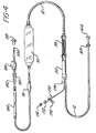
- FIGURE 4 illustrates a venous line blood set suitable for use in the arrangement of FIGURE 1.
- Flare plug 166 and leur collar 168 are located at the end of the line which connects to the output to the dialyzer 40.
- the blood tubing segment then goes to the top of the venous drip chamber 50.
- Extending from the top of the venous drip chamber 50 is an access site capped with a rubber dam 178, and a manometer line assembly 170 for connection to the solid state pressure transducer 56 and the venous pressure gauge 54 of FIGURE 1.
- the manometer line assembly 170 includes a female luer guard 174, and a slide clamp 176.
- the female luer 172 connects to a tubing segment which includes the pressure transducer 56 and a line which leads to the venous pressure gauge 54. Also located in this line would be a tee-shaped connector which connects to a tubing segment leading to the level adjust pump 52.
- a blood tubing segment 12 leads from the bottom of the venous drip chamber 50 to the flexible accumulator bag 70. From the outlet of the accumulator bag 70, the blood tubing leads to a positive pressure pillow assembly 74, and thence to a venous pump segment 180.
- the venous pump segment 180 like the arterial pump segment 130 of FIGURE 3, has a 5/16 inch interior diameter in this example.
- venous puncture site including a latex sleeve 192 and an injection site guard 194.
- a ratchet clamp 196 is coupled around the line following the puncture site.
- the venous line is terminated by a male luer 200, which will connect with the needle 10.
- the male luer 200 is protected when not in use by a hinged luer cap 198.
Abstract
Description
- This invention relates to single needle alternating blood flow systems and in particular, to single needle hemodialysis systems.
- Hemodialysis blood flow systems are employed as a therapeutic measure when a patient's kidneys no longer perform their blood purifying function by reason of disease, removal or other malfunction. Kidney failure results in the accumulation of toxic wastes in the patient's blood. Unless measures are taken to remove these wastes, the patient will experience potentially fatal uremic poisoning. Uremic poisoning may be prevented through the use of hemodialysis, by which blood is drawn from the patient and circulated through a dialyzer. In the dialyzer, the blood is separated from a specially treated dialysate fluid by a membrane which has pores of microscopic size through which waste products from the blood may pass. The microscopic pores are too small, however, to permit the passage of blood cells, proteins, and other essential elements of the blood through the membrane. The waste products thus diffuse into the dialysate fluid and are removed from the patient's blood. The purified blood is then returned to the patient's body.
- In many conventional hemodialysis systems, such as the Single Patient System (SPS) Model DM-350, produced by Extracorporeal Inc. of King of Prussia, Pennsylvania, blood is extracted from the patient through a first arterial venipuncture, which may typically be formed in a cannulation procedure. The blood is then processed by the SPS system and returned to the patient's body through a second, venous venipuncture, which may also comprise a cannula. The cannulated venipunctures, however, may not be used indefinitely. Over time, the cannulas may be gradually extruded at the exit site of the patient's body, or infection may occur. In addition, the skin over the veins will thicken after repeated hemodialysis. It then becomes necessary to surgically provide new venipunctures in the patient's body for continued hemodialysis.
- Recently, the need for two venipunctures in hemodialysis has been obviated by the development of single needle hemodialysis systems. In these systems, blood is extracted from and returned to the patient's body through a single needle with a Y-shaped junction. The patient is generally prepared for hemodialysis by the surgical implantation of an arteriovenous fistula,. which joins an artery with a nearby vein. The diversion of arterial blood into the vein causes the vein to become enlarged, permitting relatively easy insertion of the single needle into the arterialized vein, through which an adequate blood flow. for hemodialysis is developed. It has been found that fistula vessels are less traumatized by the single needle technique, and that patients benefit psychologically from the reduced number of venipunctures.
- In a typical single needle hemodialysis system, blood is alternately cycled from and to the patient's circulatory system by a single blood pump, or by arterial and venous blood pumps, respectively. During the first, or arterial, phase of operation, blood is drawn from the patient and pumped into the dialysis system by the arterial blood pump. Blood is prevented from returning to the needle by the closure of a valve located between the outlet of the arterial pump and the needle, or through clamping action of the venous blood pump. Blood pressure within the system builds until a time at which the arterial pump is turned off, the valve is opened, or the venous pump in a two-pump system is turned on to pump the blood out of the dialysis systen and back to the fistula. During this second, or venous, phase of operation, the pressure of the blood in the dialysis system drops substantially. Eventually a point is reached at which the venous pump is turned off, and the cycle repeats.
- The cyclic changeover between the arterial and venous phases may be accomplished by controlling the times of operation of the two pumps, or by activating the pumps in response to the attainment of preset pressure limits within the system. Typically, the arterial phase is characterized by the buildup of a high blood pressure within the system. This can result in undesirable high system stress, mandatory high ultrafiltration within- the dialyzer, and attendant safety concerns. On the other hand, blood pressure is subject to a precipitous decline during the venous phase as the blood is pumped back to the fistula. The attainment of a very low or negative blood pressure in the system can reverse the necessary blood to dialysate pressure differential across the dialyzer membrane (TMP), and can also undesirably result in blood foaming and the mixing of venous and arterial blood at the single needle junction. Accordingly, it is desirable to reduce or eliminate these adverse effects of blood pressure differential in a single needle hemodialysis system.
- In accordance with the principles of the present invention, a single needle hemodialysis system is provided which maintains a substantially constant pressure reference in the blood tubing system. During the arterial phase of operation, blood is drawn through the single needle and is pumped through a dialyzer and into a flexible accumulator. The accumulator expands readily as it is filled, thereby generating substantially no back pressure as it is being filled. The only significant pressure change is the pressure drop resulting from blood flow through the dialyzer. Venous pressure therefore remains at approximately zero gage until the expansive limits of the accumulator are reached. At this time, a pressure rise is detected, the arterial phase is terminated, and the venous phase is initiated. Blood is withdrawn from the accumulator, which collapses as the blood is returned through the single needle. Thus, the pressure in the dialyzer remains substantially at zero gage as the blood is returned to the patient. When a sufficient amount of blood has been returned to the patient, the venous cycle is terminated and the cycle repeats.
- It may be seen that this technique results in substantial blood flow through the dialyzer during the arterial phase of operation, and the maintenance of substantially zero gage blood pressure in the dialyzer during the venous phase. The blood pressure differential between the two phases of operation is kept at a very low level.
- In the drawings:
- FIGURE 1 shows the blood circulation path of a single needle hemodialysis system constructed in accordance with the principles of the present invention; and
- FIGURES 2a and 2b graphically represent blood pressures at the inlet and outlet of the dialyzer of FIGURE 1;
- FIGURE 3 illustrates an arterial line blood tubing set suitable for use in the arrangement of FIGURE 1; and
- FIGURE 4 illustrates a venous line blood tubing set suitable for use .in the arrangement of FIGURE 1.
- Referring to FIGURE 1, the blood flow path of a hemodialysis system is shown, including a
single needle 10 suitable for the transfer of blood from and to a patient. In FIGURE 1, the arrows indicate the direction of the flow of blood through the system. - From the
single needle 10, blood flows through theblood tubing 12 to a negativepressure pillow switch 14. Thepillow switch 14 includes a pillow-like section oftubing 16 and a sensor or switch 18 which is responsive to a relaxation of pressure in the pillow-like section 16. When the pillow pressure declines below a certain level the sensor or switch responds by initiating a system alarm as well as other procedures which interrupt the operation of the system. - Fron the
pillow switch 14 the blood tubing is connecteo through an arterial roller blood pump 20. The arterial blood pump 20 operates under control of acontroller 100, as will be described subsequently. The blood tubing is then connected to a post-pumparterial drip chamber 30 which collects blood and accommodates the connection of various gauges to the system. The pressure in thedrip chanber 30 is monitored by an arterialmechanical gauge 32 with alarm contacts. The blood level within thechamber 30 may be varied through the operation of a blood level adjustroller pump 34, by which air may be added to or subtracted from the chamber. The outlet of thedrip chamber 30 is connected by blood tubing to the inlet of acapillary dialyzer 40. In the dialyzer, impurities in the blood pass through the dialyzer membrane and into dialysate fluid, which flows into and out of the dialyzer through separate ports under control of a dialysate preparation system (not shown). - Purified blood flows out of the
dialyzer 40 and into avenous drip chamber 50. The pressure within thevenous drip chamber 50 is monitored by a mechanicalvenous pressure gauge 54 with alarm contacts. A second blood level adjustpump 52 is connected to thedrip chamber 50 to add or subtract air from the chamber, thereby adjusting the blood level within the chamber. In a tubing line between thevenous drip chamber 50 and thevenous pressure gauge 54 is a solidstate pressure transducer 56 which controls the cycling of the blood pumps and also provides another monitor of venous blood pressure. Thevenous drip chamber 50 further includes afilter 58 located within the chamber. - An air/foam detector 60 is located next to the
venous drip chanber 50. The detector 60 ultrasonically or optically detects the presence of an abnormal amount of air or foam in the blood and also monitors the blood level in thechamber 50. The detector responds to the occurence of such an abnormality by activating aclamp 62, which clamps the blood tubing closed to prevent the pumping of foam and air bubbles into the patient's circulatory system. - The blood tubing is then connected to the inlet of a vinyl accumulator bag 70. The outlet of the accumulator bag 70 is coupled to a positive
pressure pillow switch 72, which may be merely an extension of the accumulator bag 70 or, as shown in FIGURE 1, may include its own pillow-shapedtubing section 74. Abnormal expansion of the pillow-shapedsection 74 in response to an undesirable. buildup of blood pressure causes the sensor or switch portion 76 to set off an alarm and to interrupt system operation. - From the
pillow switch 72 the blood tubing passes through a venous roller blood pump 80 which is operated under control of thecontroller 100. The blood tubing then passes through a second air/foam detector 90, which is connected into the system alarm by thecontroller 100. Finally, the blood tubing is connected to theneedle 10 to return the purified blood to the patient's circulatory system. - In operation, the arterial blood pump 20 of FIGURE 1 is activated by the
controller 100 to begin withdrawing blood from the patient through theneedle 10. The negative pressure pillow switch safeguards against the withdrawal of blood at too great a rate, as indicated by the development of a negative pressure at the switch. Withdrawal of blood at too great a rate by the arterial pump can lead to collapse of the patient's fistula, blood foaming or recirculation of purified blood at the needle junction. The pillow switch also guards against any blockage of blood flow-in the fistula and needle, which condition activates a system shutdown. - The patient's blood is pumped through the
blood tubing 12, thearterial drip chamber 30, and into thedialyzer 40. The flow of blood is virtually unimpeded up to the dialyzer, at which point the pressure developed by the arterial pump forces the blood through the capillaries of the dialyzer. The dialyzer consitutes the only significant pressure drop between the arterial blood pump 20 and the accumulator bag. This pressure drop will vary with the type of dialyzer. FIGURE 2a illustrates the typical inlet pressure of a capillary-type dialyzer. During the arterial phase of operation, when the arterial blood pump 20 is running, the dialyzer inlet pressure in this example is seen to remain substantially at 20-25 mn relative to atmospheric pressure, which would be indicated on thearterial gage 32. - At the outlet of the dialyzer, however, blood pressure remains substantially at 0 mm (gauge), as shown in FIGURE 2b. This is because the purified blood is free to flow into the
venous drip chamber 50, and then into the accumulator bag 70. The accumulator bag is initially empty, and easily fills with blood from the drip chamber, since the outside of the bag is referenced to atmospheric pressure. Thus, as the accumulator bag fills, it produces substantially no back pressure which would impede the flow of blood out of the dialyzer. Furthermore, since the accumulator bag is referenced to atmospheric pressure, the pressure sensing devices at the outlet side of the dialyzer, such as thevenous pressure gauge 54 and thepressure transducer 56, can indicate the accumulator bag pressure directly by being similarly referenced to atmospheric pressure. - The accumulator bag fills freely with blood until full, at which time its expansive limits are approached and the pressure in the accumulator bag and venous drip chamber begins to rise, as indicated at 102 in FIGURE 2b. This rise in pressure is translated back to the inlet side of the dialyzer, as shown at 104 of FIGURE 2a. The rise in pressure is indicated by both the arterial and venous
mechanical gages state pressure transducer 56. Thetransducer 56 sends a signal to thecontroller 100. Thecontroller 100, which may include a microprocessor, for instance, responds to the attainment of a predetermined pressure level at the dialyzer outlet, in this example, 20 mm, by stopping operation of the arterial blood pump and initiating . operation of the venous blood pump 80. The positivepressure pillow switch 72 guards against the attainment of an unusually high venous pressure by shutting down the system if such pressures are approached. - The venous blood pump 80 is operated for a given number of cycles to remove the blood from the accumulator bag and return it to the patient's system. Pump cycles may be used as the measure of this venous phase of operation since each pump cycle corresponds to the pumping of a known volume of blood. The number of pump cycles required to empty the accumulator bag may also be determined since the capacity of the bag when full is a known quantity, the blood levels in the
drip chambers - As blood is returned to the patient the venous pressure at the outlet of the dialyzer rapidly falls back to zero mm gauge, as shown in FIGURE 2b, as the accumulator bag quickly relaxes. At the same time, the blood.pressure at the inlet side of the dialyzer drops back toward zero gage pressure since the arterial blood pump is turned off. This means that blood flow through the dialyzer occurs primarily during the arterial phase of the system, when the arterial blood pump is forcing blood through the dialyzer. Since the dialyzer pressure does not go below zero as the accumulator bag is emptied, undesirable negative transmembrane pressures are not produced in the system. While the blood is being returned to the patient during the venous phase, the air/foam detector 90 monitors the returning blood and alerts the
controller 100 if an undesirable amount of air or foam is contained in the blood. When the desired amount of blood has been returned to the patient, the controller terminates the venous phase by stopping the blood pump 80 and initiates operation of the arterial pump 20 to begin another arterial phase of operation. The phasing of blood pump operation is described more fully in concurrently filed United States patent application number (ECP-73), entitled "DUAL PHASE BLOOD FLOW SYSTEM AND METHOD OF OPERATION" ,. and in our corresponding European Patent Application filed contemporaneously herewith. - As discussed above, the pressure within the flexible accumulator bag 70 remains at zero relative to atmospheric pressure until the time at which the bag becomes full and taut. At that time the venous pressure exhibits a rapid, detectable rise. In order for the pressure rise to be relatively rapid and easily identifiable, it is desirable for the accumulator bag to resist increases in volume when full, as by exhibiting minimal or zero stretch characteristics. The bag should have a maximum capacity, and hence it should not ballon or stretch when full. However, a minimal stretch characteristic means that the bag could be susceptible to rupturing if pumpinc phase changeover does not occur promptly. Accordingly, in accordance with the principles of a further aspect of the present invention, the accumulator bag 70 in FIGURE 1 may be located in a rigid tube 78 made of a plastic, material, which will surround the bag 70 and prevent rupturing at the bag seams. Locating the bag in the tube will increase its burst pressure from 10 lbs. to 25 lbs. , for example. Alternately, the rigid tube 78 may be replaced with a non-stretch jacket, mylar sleeve or sock, which performs the same restraining function. As a further alternative, a specially manufactured bag may be constructed to have exceptional burst-resistance characteristics, as by the use of a fiber reinforced bag, for instance. A bag with a higher burst pressure provides an extra measure of safety in the arrangement of FIGURE 1.
- An arterial line blood set suitable for use in the arrangement of FIGURE 1 is illustrated in detail in FIGURE 3. A
male luer 110 is connected to the end of atubing section 12. Themale luer 110 connects to one segment of thesingle needle 10 of FIGURE 1, and is protected when not in use by a hinged cap 112. Aratchet clamp 114 is located on the tubing section following the male luer. - Following the ratchet clamp is a puncture site, including a
latex sleeve 116 and aninjection site guard 118. Blood samples may be taken from the puncture site by inserting a hypodermic needle through thelatex sleeve 116 and into thetubing section 12. The latex sleeve will provide a seal after the hypodermic needle is withdrawn. The negativepressure pillow assembly 16 is located in the blood tubing line following the puncture site. - An
administration line assembly 120 is connected to the blood tubing set by a tee-shapedconnector 128. A female luer is capped by aluer guard cap 124 when not in use. Aslide clamp 126 is located on the tubing section of the administration line. The administration line may be used to inject solutions such as saline into the blood line. - The arterial blood pump segment 130 follows the administration line. The pump segment 130 is looped through the arterial roller pump 20 and generally has a larger diameter than the normal
blood tubing segments 12. In this example, the arterial pump segment 130 has an inside diameter of 5/16 of an inch. - A
heparin administration line 140 is coupled to the blood tubing set by a tee-shapedconnector 148 following the pump segment 130. Afemale luer 142 with anend cap 144 is connected at the end of the heparin line. Aslide clamp 146 is located on the heparin line tube segment. The blood tubing next goes to thearterial drip chamber 30. - Extending from the top of the
arterial drip chamber 30 is a manometer gauge line assembly 150 for connection to thearterial pressure gauge 32 and the level adjustpump 34. The manometer line assembly 150 is terminated by afemale luer 152 with aprotective cap 154. Aslide clamp 156 is also located on the gauge line. An access site is also located at the top of thedrip chamber 30, and is capped by -a rubber dam ordiaphragm 160. - At the end of the blood tubing segment extending from the bottom of the
arterial drip chamber 30 is aflare plug 164, which is used to seal the end of the tubing segment when not in use. Aluer collar 162 is located about the tubing set near the end and is used to clamp the blood tubing set onto the inlet of the dialyzer. - FIGURE 4 illustrates a venous line blood set suitable for use in the arrangement of FIGURE 1.
Flare plug 166 and leurcollar 168 are located at the end of the line which connects to the output to thedialyzer 40. The blood tubing segment then goes to the top of thevenous drip chamber 50. Extending from the top of thevenous drip chamber 50 is an access site capped with arubber dam 178, and amanometer line assembly 170 for connection to the solidstate pressure transducer 56 and thevenous pressure gauge 54 of FIGURE 1. Themanometer line assembly 170 includes afemale luer guard 174, and aslide clamp 176. When used in the arrangement of FIGURE 1 thefemale luer 172 connects to a tubing segment which includes thepressure transducer 56 and a line which leads to thevenous pressure gauge 54. Also located in this line would be a tee-shaped connector which connects to a tubing segment leading to the level adjustpump 52. - A
blood tubing segment 12 leads from the bottom of thevenous drip chamber 50 to the flexible accumulator bag 70. From the outlet of the accumulator bag 70, the blood tubing leads to a positivepressure pillow assembly 74, and thence to avenous pump segment 180. Thevenous pump segment 180, like the arterial pump segment 130 of FIGURE 3, has a 5/16 inch interior diameter in this example. - From the
venous pump segment 180 the blood tubing goes through a venous puncture site, including alatex sleeve 192 and aninjection site guard 194. A ratchet clamp 196 is coupled around the line following the puncture site. The venous line is terminated by amale luer 200, which will connect with theneedle 10. Themale luer 200 is protected when not in use by a hingedluer cap 198.
Claims (18)
Applications Claiming Priority (2)
| Application Number | Priority Date | Filing Date | Title |
|---|---|---|---|
| US06/423,380 US4490135A (en) | 1982-09-24 | 1982-09-24 | Single needle alternating blood flow system |
| US423380 | 1982-09-24 |
Publications (2)
| Publication Number | Publication Date |
|---|---|
| EP0104897A2 true EP0104897A2 (en) | 1984-04-04 |
| EP0104897A3 EP0104897A3 (en) | 1984-10-03 |
Family
ID=23678696
Family Applications (1)
| Application Number | Title | Priority Date | Filing Date |
|---|---|---|---|
| EP83305637A Withdrawn EP0104897A3 (en) | 1982-09-24 | 1983-09-22 | Single needle alternating blood flow system |
Country Status (6)
| Country | Link |
|---|---|
| US (1) | US4490135A (en) |
| EP (1) | EP0104897A3 (en) |
| JP (1) | JPS59131358A (en) |
| BR (1) | BR8305230A (en) |
| ES (2) | ES8501237A1 (en) |
| NO (1) | NO833440L (en) |
Cited By (4)
| Publication number | Priority date | Publication date | Assignee | Title |
|---|---|---|---|---|
| EP0132047A1 (en) * | 1983-06-15 | 1985-01-23 | McNeilab, Inc. | Hemodialysis access monitor |
| EP0161686A2 (en) * | 1984-05-18 | 1985-11-21 | Fresenius AG | Method for filling the blood tubing system of a hemodialysing device with a saline solution |
| US5227049A (en) * | 1990-08-20 | 1993-07-13 | Hospal Industrie | Single-needle circuit for circulating blood outside the body in blood treatment apparatus |
| EP1425063B2 (en) † | 2001-07-07 | 2018-10-31 | NxStage Medical, Inc. | System for leak detection in a fluid line |
Families Citing this family (49)
| Publication number | Priority date | Publication date | Assignee | Title |
|---|---|---|---|---|
| US5034135A (en) * | 1982-12-13 | 1991-07-23 | William F. McLaughlin | Blood fractionation system and method |
| US4604089A (en) * | 1983-08-15 | 1986-08-05 | Codman & Shurtleff, Inc. | Pressure regulated irrigation system for arthroscopy |
| US5047147A (en) * | 1983-11-23 | 1991-09-10 | Hospal Industrie | Single-needle artificial kidneys |
| CA1261765A (en) * | 1984-03-21 | 1989-09-26 | Donald W. Schoendorfer | Method and apparatus for separation of matter from suspension |
| JPS61253069A (en) * | 1985-05-01 | 1986-11-10 | クリエ−トメデイツク株式会社 | Single needle diagnostic circuit apparatus with storage battery |
| US4854836A (en) * | 1986-02-18 | 1989-08-08 | Baxter International Inc. | Collapsible conduit for linear peristaltic pump and method of making the same |
| BE905615R (en) * | 1986-09-10 | 1987-04-17 | Hombrouckx Remi O J | METHOD AND EQUIPMENT FOR SINGLE NEEDLE MODIALYSIS. |
| US4919649A (en) * | 1987-09-30 | 1990-04-24 | Sherwood Medical Company | Fluid delivery system |
| US5803712A (en) | 1988-05-17 | 1998-09-08 | Patient Solutions, Inc. | Method of measuring an occlusion in an infusion device with disposable elements |
| US5074756A (en) | 1988-05-17 | 1991-12-24 | Patient Solutions, Inc. | Infusion device with disposable elements |
| US5246347A (en) | 1988-05-17 | 1993-09-21 | Patients Solutions, Inc. | Infusion device with disposable elements |
| DE3923836C1 (en) * | 1989-07-19 | 1990-09-20 | Fresenius Ag, 6380 Bad Homburg, De | |
| US5059173A (en) * | 1990-04-04 | 1991-10-22 | Sacco John J | IV apparatus |
| US5061365A (en) * | 1991-01-22 | 1991-10-29 | Utterberg David S | Medical fluid flow set |
| FR2672218B1 (en) * | 1991-02-06 | 1998-04-24 | Hospal Ind | DEVICE AND METHOD FOR LEVELING A LIQUID IN A CHAMBER OF AN EXTRACORPOREAL BLOOD CIRCUIT. |
| US5399160A (en) * | 1991-10-04 | 1995-03-21 | Minnesota Mining And Manufacturing Company | Irrigation tubing set having compliant sections |
| US6113554A (en) * | 1998-10-16 | 2000-09-05 | Haemonetics Corporation | Automatic whole blood collection system |
| US6726647B1 (en) * | 1998-10-23 | 2004-04-27 | Gambro Ab | Method and device for measuring access flow |
| TW519618B (en) * | 2001-05-11 | 2003-02-01 | Via Tech Inc | Compact disc player with pick-up head sled and adaptive compensator |
| US6863821B2 (en) * | 2002-02-02 | 2005-03-08 | Baxter International Inc. | Shear-enhanced systems and methods for removing waste materials and liquid from the blood |
| US7351218B2 (en) * | 2002-12-20 | 2008-04-01 | Gambro Lundia Ab | Device and process for extracorporeal treatment by citrate anticoagulant |
| FR2848857B1 (en) | 2002-12-20 | 2005-09-16 | Gambro Lundia Ab | SINGLE-USE DEVICE AND LINE FOR THE EXTRACORPOREAL TREATMENT OF BLOOD BY CITRATE ANTICOAGULATION |
| ITMO20030293A1 (en) * | 2003-10-29 | 2005-04-30 | Gambro Lundia Ab | DEVICE FOR THE DETERMINATION OF THE BLOOD FLOW IN AN EXTRACORPOREO CIRCUIT, AS WELL AS THE EQUIPMENT FOR BLOOD TREATMENT USING THE SAME DEVICE. |
| US8029454B2 (en) | 2003-11-05 | 2011-10-04 | Baxter International Inc. | High convection home hemodialysis/hemofiltration and sorbent system |
| DE102005001779B4 (en) * | 2005-01-14 | 2009-12-17 | Fresenius Medical Care Deutschland Gmbh | Disposable for operating a blood treatment device in single-needle or two-needle operation |
| DE102007026009A1 (en) * | 2007-06-04 | 2009-01-02 | Fresenius Medical Care Deutschland Gmbh | Apparatus and method for blood treatment in single-needle operation |
| US8702637B2 (en) | 2008-04-14 | 2014-04-22 | Haemonetics Corporation | System and method for optimized apheresis draw and return |
| US8961789B2 (en) * | 2008-10-31 | 2015-02-24 | Baxter International Inc. | Systems and methods for performing hemodialysis |
| EP2415491B1 (en) * | 2010-08-02 | 2014-06-04 | Gambro Lundia AB | Extracorporeal blood treatment apparatus |
| US11386993B2 (en) | 2011-05-18 | 2022-07-12 | Fenwal, Inc. | Plasma collection with remote programming |
| JP6001660B2 (en) | 2011-08-02 | 2016-10-05 | メドトロニック,インコーポレイテッド | Hemodialysis system having a flow path with controlled follow-up volume |
| EP2744537B1 (en) | 2011-08-16 | 2018-01-24 | Medtronic, Inc. | Modular hemodialysis system |
| US10905816B2 (en) | 2012-12-10 | 2021-02-02 | Medtronic, Inc. | Sodium management system for hemodialysis |
| US10543052B2 (en) | 2013-02-01 | 2020-01-28 | Medtronic, Inc. | Portable dialysis cabinet |
| US10850016B2 (en) * | 2013-02-01 | 2020-12-01 | Medtronic, Inc. | Modular fluid therapy system having jumpered flow paths and systems and methods for cleaning and disinfection |
| US10010663B2 (en) | 2013-02-01 | 2018-07-03 | Medtronic, Inc. | Fluid circuit for delivery of renal replacement therapies |
| US9623164B2 (en) | 2013-02-01 | 2017-04-18 | Medtronic, Inc. | Systems and methods for multifunctional volumetric fluid control |
| US10874787B2 (en) | 2014-12-10 | 2020-12-29 | Medtronic, Inc. | Degassing system for dialysis |
| US10098993B2 (en) | 2014-12-10 | 2018-10-16 | Medtronic, Inc. | Sensing and storage system for fluid balance |
| US9895479B2 (en) | 2014-12-10 | 2018-02-20 | Medtronic, Inc. | Water management system for use in dialysis |
| US9713665B2 (en) | 2014-12-10 | 2017-07-25 | Medtronic, Inc. | Degassing system for dialysis |
| WO2017001358A1 (en) | 2015-06-29 | 2017-01-05 | Gambro Lundia Ab | Extracorporeal blood circuit for single-needle treatments |
| US10758652B2 (en) | 2017-05-30 | 2020-09-01 | Haemonetics Corporation | System and method for collecting plasma |
| US10792416B2 (en) | 2017-05-30 | 2020-10-06 | Haemonetics Corporation | System and method for collecting plasma |
| US11278654B2 (en) | 2017-12-07 | 2022-03-22 | Medtronic, Inc. | Pneumatic manifold for a dialysis system |
| US11033667B2 (en) | 2018-02-02 | 2021-06-15 | Medtronic, Inc. | Sorbent manifold for a dialysis system |
| US11110215B2 (en) | 2018-02-23 | 2021-09-07 | Medtronic, Inc. | Degasser and vent manifolds for dialysis |
| DK3621674T3 (en) | 2018-05-21 | 2021-12-06 | Fenwal Inc | PLASMA COLLECTION VOLUME OPTIMIZATION SYSTEMS |
| US11412967B2 (en) | 2018-05-21 | 2022-08-16 | Fenwal, Inc. | Systems and methods for plasma collection |
Citations (8)
| Publication number | Priority date | Publication date | Assignee | Title |
|---|---|---|---|---|
| DE2415528A1 (en) * | 1973-04-06 | 1974-10-24 | Gen Electric | DEVICE FOR DETERMINING AND DISPLAYING THE PRESSURE AND VOLUME OF LIQUIDS |
| DE2522180A1 (en) * | 1974-12-23 | 1976-11-18 | Tokyo Shibaura Electric Co | ARTIFICIAL KIDNEY |
| DE2636290A1 (en) * | 1976-08-12 | 1978-02-16 | Fresenius Chem Pharm Ind | DEVICE FOR CONTROLLING AND MONITORING BLOOD FLOW DURING BLOOD DIALYSIS, PERFUSION AND DIAFILTRATION USING ONLY ONE CONNECTION POINT TO THE PATIENT'S BLOOD CIRCUIT (SINGLE NEEDLE TECHNOLOGY) |
| DE2745347A1 (en) * | 1976-10-14 | 1978-04-20 | Gambro Ab | HOSE SET |
| GB2040379A (en) * | 1979-01-23 | 1980-08-28 | Baxter Travenol Lab | Connector for tubing |
| US4224943A (en) * | 1979-01-24 | 1980-09-30 | Sorenson Research Co., Inc. | Cannula and method for bidirectional blood flow |
| EP0033080A2 (en) * | 1980-01-23 | 1981-08-05 | ASID BONZ & SOHN GMBH | Flexible tube system for dialysis |
| EP0071951A1 (en) * | 1981-08-05 | 1983-02-16 | Fresenius AG | Device for blood purification |
Family Cites Families (10)
| Publication number | Priority date | Publication date | Assignee | Title |
|---|---|---|---|---|
| US3140714A (en) * | 1962-06-28 | 1964-07-14 | Cordis Corp | Blood separation method |
| US3830234A (en) * | 1971-06-04 | 1974-08-20 | Vital Assists | Dialysis control system and method |
| US3756234A (en) * | 1971-06-04 | 1973-09-04 | Vital Assists | Single needle dialysis |
| FR2198759B1 (en) * | 1972-09-12 | 1976-06-04 | Rhone Poulenc Ind | |
| DE2455214A1 (en) * | 1974-11-06 | 1976-05-13 | Charles B Willock | SINGLE NEEDLE BLOOD PUMP SYSTEM |
| US3964479A (en) * | 1974-11-20 | 1976-06-22 | Cobe Laboratories, Inc. | Extracorporeal blood circulation system and drip chamber with adjustable blood level |
| US4146028A (en) * | 1977-03-29 | 1979-03-27 | Burron Medical Products, Inc. | Intravenous system having an accumulator tube therein |
| US4228930A (en) * | 1977-09-09 | 1980-10-21 | Cole-Parmer Instrument Company | Dispensing pump |
| US4218197A (en) * | 1978-07-06 | 1980-08-19 | Beckman Instruments, Inc. | Combined peristaltic pump and valve flow controller |
| US4385630A (en) * | 1980-08-29 | 1983-05-31 | Haemonetics Corporation | Blood donation unit |
-
1982
- 1982-09-24 US US06/423,380 patent/US4490135A/en not_active Expired - Fee Related
-
1983
- 1983-09-22 EP EP83305637A patent/EP0104897A3/en not_active Withdrawn
- 1983-09-22 JP JP58176113A patent/JPS59131358A/en active Pending
- 1983-09-23 BR BR8305230A patent/BR8305230A/en unknown
- 1983-09-23 ES ES525919A patent/ES8501237A1/en not_active Expired
- 1983-09-23 NO NO833440A patent/NO833440L/en unknown
-
1984
- 1984-07-27 ES ES1984280738U patent/ES280738Y/en not_active Expired
Patent Citations (8)
| Publication number | Priority date | Publication date | Assignee | Title |
|---|---|---|---|---|
| DE2415528A1 (en) * | 1973-04-06 | 1974-10-24 | Gen Electric | DEVICE FOR DETERMINING AND DISPLAYING THE PRESSURE AND VOLUME OF LIQUIDS |
| DE2522180A1 (en) * | 1974-12-23 | 1976-11-18 | Tokyo Shibaura Electric Co | ARTIFICIAL KIDNEY |
| DE2636290A1 (en) * | 1976-08-12 | 1978-02-16 | Fresenius Chem Pharm Ind | DEVICE FOR CONTROLLING AND MONITORING BLOOD FLOW DURING BLOOD DIALYSIS, PERFUSION AND DIAFILTRATION USING ONLY ONE CONNECTION POINT TO THE PATIENT'S BLOOD CIRCUIT (SINGLE NEEDLE TECHNOLOGY) |
| DE2745347A1 (en) * | 1976-10-14 | 1978-04-20 | Gambro Ab | HOSE SET |
| GB2040379A (en) * | 1979-01-23 | 1980-08-28 | Baxter Travenol Lab | Connector for tubing |
| US4224943A (en) * | 1979-01-24 | 1980-09-30 | Sorenson Research Co., Inc. | Cannula and method for bidirectional blood flow |
| EP0033080A2 (en) * | 1980-01-23 | 1981-08-05 | ASID BONZ & SOHN GMBH | Flexible tube system for dialysis |
| EP0071951A1 (en) * | 1981-08-05 | 1983-02-16 | Fresenius AG | Device for blood purification |
Cited By (5)
| Publication number | Priority date | Publication date | Assignee | Title |
|---|---|---|---|---|
| EP0132047A1 (en) * | 1983-06-15 | 1985-01-23 | McNeilab, Inc. | Hemodialysis access monitor |
| EP0161686A2 (en) * | 1984-05-18 | 1985-11-21 | Fresenius AG | Method for filling the blood tubing system of a hemodialysing device with a saline solution |
| EP0161686A3 (en) * | 1984-05-18 | 1987-09-02 | Fresenius Ag | Method and device for filling the blood tubing system of a hemodialysing device with a saline solution |
| US5227049A (en) * | 1990-08-20 | 1993-07-13 | Hospal Industrie | Single-needle circuit for circulating blood outside the body in blood treatment apparatus |
| EP1425063B2 (en) † | 2001-07-07 | 2018-10-31 | NxStage Medical, Inc. | System for leak detection in a fluid line |
Also Published As
| Publication number | Publication date |
|---|---|
| US4490135A (en) | 1984-12-25 |
| BR8305230A (en) | 1984-05-02 |
| ES280738U (en) | 1985-02-16 |
| NO833440L (en) | 1984-03-26 |
| ES525919A0 (en) | 1984-11-16 |
| ES8501237A1 (en) | 1984-11-16 |
| ES280738Y (en) | 1985-09-16 |
| JPS59131358A (en) | 1984-07-28 |
| EP0104897A3 (en) | 1984-10-03 |
Similar Documents
| Publication | Publication Date | Title |
|---|---|---|
| US4490135A (en) | Single needle alternating blood flow system | |
| EP1339315B1 (en) | Apparatus for blood withdrawal and infusion using a pressure controller | |
| US7004924B1 (en) | Methods, systems, and kits for the extracorporeal processing of blood | |
| KR101487425B1 (en) | Hemodializer | |
| EP1480713B1 (en) | Apparatus for an extracorporeal treatment device to control blood withdrawal and infusion | |
| EP2044965B1 (en) | Apparatus for body fluid flow control in extracorporeal fluid treatments | |
| US7998101B2 (en) | Devices and methods for body fluid flow control in extracorporeal fluid treatment | |
| US4501583A (en) | Hemodialysis access monitors | |
| US4490134A (en) | Dual phase blood flow system and method of operation | |
| US20130178781A1 (en) | Extracorporeal blood treatment apparatus | |
| WO2023032960A1 (en) | Blood purification device |
Legal Events
| Date | Code | Title | Description |
|---|---|---|---|
| PUAI | Public reference made under article 153(3) epc to a published international application that has entered the european phase |
Free format text: ORIGINAL CODE: 0009012 |
|
| AK | Designated contracting states |
Designated state(s): AT BE CH DE FR GB IT LI LU NL SE |
|
| PUAL | Search report despatched |
Free format text: ORIGINAL CODE: 0009013 |
|
| AK | Designated contracting states |
Designated state(s): AT BE CH DE FR GB IT LI LU NL SE |
|
| RAP1 | Party data changed (applicant data changed or rights of an application transferred) |
Owner name: BAXTER TRAVENOL LABORATORIES, INC. |
|
| 17P | Request for examination filed |
Effective date: 19850315 |
|
| STAA | Information on the status of an ep patent application or granted ep patent |
Free format text: STATUS: THE APPLICATION IS DEEMED TO BE WITHDRAWN |
|
| 18D | Application deemed to be withdrawn |
Effective date: 19860523 |
|
| RIN1 | Information on inventor provided before grant (corrected) |
Inventor name: TROUTNER, VERNON H. |