EP0105707A1 - Apparatus for scaling fascimile image data - Google Patents
Apparatus for scaling fascimile image data Download PDFInfo
- Publication number
- EP0105707A1 EP0105707A1 EP83305821A EP83305821A EP0105707A1 EP 0105707 A1 EP0105707 A1 EP 0105707A1 EP 83305821 A EP83305821 A EP 83305821A EP 83305821 A EP83305821 A EP 83305821A EP 0105707 A1 EP0105707 A1 EP 0105707A1
- Authority
- EP
- European Patent Office
- Prior art keywords
- image
- pels
- new
- pel
- grey scale
- Prior art date
- Legal status (The legal status is an assumption and is not a legal conclusion. Google has not performed a legal analysis and makes no representation as to the accuracy of the status listed.)
- Granted
Links
Images


Classifications
-
- G—PHYSICS
- G06—COMPUTING; CALCULATING OR COUNTING
- G06T—IMAGE DATA PROCESSING OR GENERATION, IN GENERAL
- G06T3/00—Geometric image transformation in the plane of the image
- G06T3/40—Scaling the whole image or part thereof
-
- H—ELECTRICITY
- H04—ELECTRIC COMMUNICATION TECHNIQUE
- H04N—PICTORIAL COMMUNICATION, e.g. TELEVISION
- H04N1/00—Scanning, transmission or reproduction of documents or the like, e.g. facsimile transmission; Details thereof
- H04N1/40—Picture signal circuits
- H04N1/40068—Modification of image resolution, i.e. determining the values of picture elements at new relative positions
Definitions
- This invention relates to an apparatus and method for converting image data of a first image field to data of a second image field having a different resolution.
- Computer users of on-line displays frequently access image facsimile data which occurs in scanned lines.
- a large number of picture elements or pels each comprising data representing the grey scale of a respective point in an image, are generated at regular time intervals depending on the sampling frequency used.
- the CCITT standard prescribes numbers of pels per inch suitable to produce adequate clarity.
- the pels are digital data specifying a particular grey scale of each point in the image, and each scan line forms one row of pels in a two-dimensional matrix.
- the individual pels of a plurality of successive scan lines form columns of pels, the columns and rows constituting a matrix of N rows and M columns.
- the matrix is stored in a memory and supplied to a user for display when required.
- Displays and printers used in connection with large scale computer systems typically require image data which is comprised of a smaller number of pels derived from a larger image matrix containing more pels.
- the conversion process should reduce the matrix of pels from N 1 x M 1 to N 2 x M 2 with a minimum loss in picture detail.
- the process of converting one matrix of image data to a second matrix of image data having a different resolution has in the past involved computation of a grey scale for each new pel with an algorithm-controlled processor.
- the processor calculates the grey scale level of the new pel considering the contribution of grey scale level from the pels of the original matrix which constitute the four nearest neighbours to the new image pel as: where dx, dy, are the distances of the new image pel T (K,L) to the upper left neighbour S i,j of the original matrix. S i,j+1 , S i+1,j and S i+1, j+1 are the grey scale levels for the remaining neighbours of the new image pel.
- the present invention provides apparatus for converting first image data, comprising a matrix of rows and columns of image pels each comprising grey scale data of a corresponding point on an original image, to a matrix of second image data of different resolution, the apparatus comprising: means for forming a first scale factor corresponding to the ratio of the resolution of the first image to that of the second image in the row direction, means for forming a second scale factor corresponding to the ratio of the resolution of the first image to that of the second image in the column direction, means for multiplying the row coordinate of each successive column of second image pels by the first scale factor to give, in each case, a whole number TAB# and a fractional remainder AX, means for storing each successive TAB# and AX, means for multiplying the column coordinate of each successive row of second image pels by the second scale factor to give, in each case, a whole number NEXT PAIR and a fractional remainder AY, means for storing each successive NEXT PAIR and AY, means responsive to the stored values
- grey scale levels of the original image are restricted to 0 and 1, and the distances dx, dy are rounded to the nearest 1/8.
- the four original image pels which form the nearest neighbours of each new image pel are identified, as well as the position of the new pel with respect to each such neighbour.
- a look-up table is provided which is addressed according to the grey scale of each neighbour pel and the position of the new pel within its respective four-pel neighbourhood. By grey scale, it is intended to cover the situation wherein each image pel is represented by one of two grey scale levels only, which is either I or 0.
- the look-up table comprises a memory organised in planes, each plane containing addressable rows and columns of storage cells.
- Each plane corresponds to a respective one of the plurality of possible grey scale combinations of each four-pel neighbourhood
- each storage cell within a given plane corresponds to a respective one of the plurality of possible positions of the new pel with respect to its old image neighbours.
- each pel in a scanned image field of the type specified in ICCTT standards which prescribe the number of pels per inch for each scanned line.
- a scan line consists of 14 pels each identified by an asterisk; the number of scan lines is 8.
- Each pel comprises digital data specifying the grey scale or intensity of a corresponding point in an original image.
- each pel is a single binary digit 0 or 1, where 0 corresponds to a dark intensity level and 1 to a bright intensity level.
- a second image field of lower resolution comprising fewer pels than the first image field, each pel of the second image field being identified by a zero (o).
- the pels shown in the new image field are surrounded by the original image pels, *.
- each new pel T K , L is surrounded by four neighbour pels of the original image matrix: S i,j , S i+1,j , S i,j+,' and S i+1 , j+1 .
- the image intensity of the new pel T K,L is a function of the position of the new image pel T K,L within the neighbourhood of original image pels and the intensity of the neighbour pels.
- the aforementioned prior art algorithm provides a means for calculating the new pel grey scale level as a result of considering the old image neighbourhood pel grey scale level.
- the present embodiment provides for a convenient method, involving only a small amount of computation time, for assigning a new grey scale level to a new image pel given the grey scale levels of the four neighbours of the original image field, and the position of the new pel with respect to the old image neighbours.
- Figure 3A there are shown, as a function of position, representative values of the grey scale of a new image pel derived from the contributions of the members of the old neighbourhood pels of an image to be converted.
- Figure 3A shows an 8 x 8 matrix of grey scale levels within a neighbourhood of original image pels which are assumed to be 1, 0, 0, 1 in this case.
- the distance dx represents the 8 different possible positions for a new pel in the horizontal direction within the neighbourhood, after rounding to the nearest 1/8.
- the distance dy represents the 8 possible rounded positions of a new pel in the vertical direction. It is thus seen that the grey scale level for a new pel within the neighbourhood of Figure 3A may be conveniently identified by its position within the neighbourhood.
- the values of grey scale for a new pel shown in Figure 3A may be rounded for convenience, whereby values of 0.5 or greater are indicated to be binary 1, and values of less than 0.5 are binary 0.
- Figure 3A may be modified to that shown in Figure 3B, wherein the grey scale of a new pel within the neighbourhood having four neighbours with grey scale levels of binary 1, 0, 0 and 1 may be represented by a 1 or 0. Since each neighbourhood comprises four pels, each having a binary value of 0 or 1, all possible neighbourhoods may be represented by a total of 16 matrices as shown in Figure 3C.
- each matrix such as that shown in
- Figure 3B is considered to be a plane, corresponding to a respective one of the sixteen possible neighbourhood patterns.
- the grey scale of a new pel within any neighbourhood so represented may be determined by considering its distances dx and dy within the plane, rounded to the nearest 1/8.
- a new grey scale may be determined for the new pel within a neighbourhood.
- the sixteen planes of matrixes representing the sixteen possible neighbourhood configurations for the old image data comprise in the embodiment a look-up table which may be conveniently addressed to read out the grey scale of a new pel of an image matrix having a different resolution to the original image matrix.
- the look-up table is an addressable memory divided into planes with an 8 x 8 matrix of storage locations in each plane.
- the planes are addressed by the grey scale levels of the neighbourhood pels of the new pel, and within each plane a particular storage location is addressed by the rounded values dx and dy of the new pel.
- FIG. 4 there is shown an overall block diagram of an apparatus for converting matrix image data of a first resolution, sent from a main frame host computer 11 via a bus 15 to a terminal 17, to a different resolution.
- the host computer 11 includes a data buffer 12 and control program 13 for controlling traffic to and from the terminal 17.
- Terminal 17 similarly includes a control program 20 which cooperates with the control program 13 to receive and send data to and from the host computer 11.
- the terminal 17 is seen to contain a keyboard 19 for permitting user control of the terminal and permitting access to the host computer 11.
- a display 23 and display buffer 22 cooperate to present data generated by the keyboard and received from the data bus 15 for the user's information.
- the terminal 17 includes conversion hardware 21 which will convert image data received from the data bus 15 from a first field size, containing N 1 x M 1 pels, to a new image field of N 2 x M 2 pels.
- the conversion hardware 21 is shown more specifically in Figure 5.
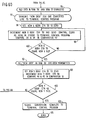
- the system of Figure 5 will be described in general terms with respect to the subsystems I-VI. Following the description of these subsystems, an example of the operation of the apparatus will be described with respect to the flow charts of Figure 6.
- Subsystems I and II compute the location of the four neighbour pels of the old image field N x M for each new image pel of the new field N 2 x M 2 .
- the term "size" here referring to the numbers N and M and not being related to the physical dimensions of the ultimate picture displayed.
- Address counters 39 and 48 generate the address of each new pel to be displayed as the new image.
- Scaling factors are produced to scale the X dimension of the new image data to identify pel neighbours of the old image field which include the new image field pels.
- Floating point multipliers 38 and 49 produce the X coordinate and Y coordinates of the neighbours of the old image data containing the new image pel.
- Two random access memories 40 and 50 store the result of floating point multiplication of the scale factors and the respective X and Y addresses of the new image pels in columns. The result of each floating point multiplication is a whole number and a fraction number.
- the whole number (NEXT PAIR) in RAM 50 identifies each pair of rows in the old image data which contains neighbours of each new image pel.
- the fraction AY resulting from the floating point multiplication is also stored in the memory 50 and locates the dy position of the new image pel with respect to the pair of rows identified by the corresponding whole number.
- memory 40 stores whole numbers shown as TAB# and the corresponding fraction A X.
- the memory 40 identifies the pairs of columns of the old image pels which include a new image pel.
- a X, the corresponding fraction, identifies the dx position between columns of the new image pel.
- subsystem I and II identify the intersecting pairs of rows and columns of the old image data which includes each new image pel.
- RAM 50 located at addresses in RAM 50 corresponding to the Y address for each new pel, are used to address the stored old image data in data buffer 12, Figure 4, through shift register 52.
- the pair of rows identified at each address of memory 50 are sequentially inserted through gates 53 and 54 into RAMS 56 and 57.
- RAMS 56 and 57, along with address counter 59 and gates 53 and 54 comprise yet another subsystem III.
- the subsystem of III holds the pels of the identified row pairs, addressed by the shift register 52, until the four neighbours of each new image pel in the pair of rows have been identified and the grey scale contribution of the neighbours to the new image pel contained within the neighbourhood have been identified.
- address counter 59 addresses each column of old image pels in RAMS 56 and 57 which are identified in memory 40.
- the output from RAMS 56 and 57 comprise the neighbours S i,j , S i,j+1 , S i+1,j and S i+1,i+1 .
- the image data grey scale levels received from RAMS 56 and 57 address one of the plurality of planes contained in the look-up table IV.
- the look- up table produces a stored grey scale level having a value which is dependent upon the grey scale of the four individual old image neighbour pels, and the position of the new image pel within the neighbourhood.
- Look-up table IV has associated with each memory location thereof eight binary values to to t 7 .
- the eight binary values, each representing a grey scale level of 1 or 0, are applied to a data selector V.
- Data selector V is under control of a threshold which is a three bit code used to select one of the to to t 7 known values. In this way weighting of the grey scale is possible, i.e. the density of binary 1 values in the resulting image may be varied.
- eight look-up tables are provided corresponding respectively to t0 as the grey scale level in each memory location, t as the grey scale level in each memory location, and so on.
- the data selector V will normally select only one of the tables for providing the grey scale levels of the new image pels, according to the density of image required.
- RAM VI assembles the new image pel grey scale levels until one scan line is produced.
- the control program 20 provides for the necessary signals to the different circuit components of Figure 5 to effect the foregoing operation.
- the system will now be described in terms of the actual steps carried on by the control program 20 to convert image data of a first size to a second size.
- the initial step 65 includes a determination that the keyboard 19 has selected a request to convert the image data from data buffer 12 to an image of a different resolution.
- the user enters from keyboard 19 in step 66 the old and new matrix sizes N 1 , M and N 2' M 2 of the image data.
- the manual operator input could be supplanted by suitable programming so that the operation could occur automatically.
- the sizes of the respective image fields are loaded in shift register 31.
- Shift register 31 is clocked by pulses from the control programmer 20 to serially produce each of the old image X size (M 1 ), new image X size (M 2 ), old image Y size (N 1 ), and new image Y size (N 2 ) in serial fashion.
- Gates 32, 33, 42 and 43 are controlled by the control tags from the control program 20 to gate at the appropriate time the respective image dimension to one of registers 35, 34, 44 and 45.
- dividers 36 and 46 produce scaling factors by dividing the old image size dimensions by the new image size dimensions in step 68.
- the result of the scale factor calculations for each coordinate direction of the matrices are stored in registers 37 and 47 respectively.
- Address counters 39 and 48 are clocked by the control program 20 to generate sequentially the address of each of the new image pels of the new matrix.
- the scale factor contained in register 37 is multiplied by each of the new pel X addresses and the result is a whole number and a fraction, identified as TAB# and A X respectively.
- the result of the multiplication is stored at an address identified by the new X address counter 39 in RAM 40.
- memory 40 will contain TAB# at each new pel X address identifying the pair of columns of the old image data which form neighbours of the new image pel.
- step 74 complete the calculation of TAB# and A X coordinates for each new pel of the new image field and store the result in memory 40. It will be appreciated that TAB# and ⁇ X need only be calculated for one line or row of new image pels, as these values will be identical for succeeding rows.
- the control program 20 provides a subsequent set of control signals for calculating the pairs of rows of old image data, NEXT PAIR, and the A Y coordinate of each new pel within the old image data in steps 75 through 81.
- the new Y address counter 48 is set to 0 in step 76.
- Each of the subsequent Y addresses produced in response to clock pulses C8 are multiplied by the scale factor contained in register 47 by floating point multiplier 49.
- comparator 51 will terminate the calculation of A Y and the next pair whole number, NEXT PAIR.
- Memory 50 contains at each new Y address the respective NEXT PAIR rows of old image data which constitute neighbours, and the position within the rows A Y of the new image pel. As for the X direction, it is only necessary to calculate NEXT PAIR and ⁇ Y for one column of the new image pels.
- step 82 the complete calculation of each new Y address of NEXT PAIR and A Y is completed.
- the first pair of lines of old image data is in step 83 identified by referring to the first memory location in memory 50.
- the NEXT PAIR identified in memory 50 is inserted in shift register 52 in step 85.
- Shift register 52 transmits the address information to the terminal control program 20.
- the control program 20 calls forth the proper two consecutive lines of old image data residing in the host computer system 11 which includes neighbours of the new image pel.
- the control program 20 transmits the pair of lines requested into RAMS 56 and 57.
- RAM 56 contains the first of the pair of lines and RAM 57 contains the second of the pair of lines.
- step 88 the two lines of old image data which contain neighbours of the new image pel are thus available.
- each TAB# in the RAM 40 identifies the columns of neighbours stored in RAMS 57 and 56.
- Old X address counter 59 addresses these columns of neighbours as each TAB # is read out from memory 40.
- the output of RAMS 57 and 56 therefore contain the image pels comprising neighbours S i, j and S i + 1,j .
- the old X address counter 59 is incremented by 1 and the neighbours S i, j+1 , and S i+1, j+1 are read from the RAMS 56 and 57.
- the four neighbours of a new pel are identified, and applied through gates under control of control program 20 to the look-up table IV.
- Look-up table IV is arranged in planes, each of the planes corresponding to the grey scale of the four neighbours.
- the individual planes of the look-up table 4 are further addressed by ⁇ X and ⁇ Y which identify the position of each new pel within the neighbourhood of pels addressing the plane.
- the eight possible binary values produced from the look-up table 4 are selected by data selector V under control of the control program 20.
- a threshold value is used to discriminate against grey scales above and below a predetermined number, between 0 and 1, which may be set by the operation via the keyboard, a potentiometer or switch, or by a program.
- the result from the data selector V is one of eight possible grey scale levels which is stored in RAM VI as the grey scale of a pel, RAM VI under control of the address counter 39 will for each new X address produced, which has identified the neighbourhood of a pel, store the grey scale level at the new X address.
- step 93 the loading of RAM VI is found to be complete when the new X address counter has an X address which is equal to the new X size.
- the decision block 94 when determining that the last new pel X address has been generated and a corresponding grey scale for a pel at the address identified is stored in RAM VI, indicates that the data in RAMS 56 and 57 has been completely processed.
- the line of new image pels assembled in RAM VI is transmitted to the terminal control program 20 for use by the display buffer.
- the new address counter is set to 0 in step 98, and then incremented in step 99.
- decision block 100 the new X address is compared with the new X size, and the X address counter 39 is continued to be incremented until the decision block 100 provides a yes indication.
- step 101 indicates that all the new data in the RAM VI has been sent to the program controller, and in step 102 the new X address counter 39 is reset to 0.
- the new Y address counter is incremented and once again compared with the Y dimension of the new image matrix. It there is not an equivalence found, further Y addresses are produced, and the flow chart returns to step 83 to get two more lines of old data for storage in RAMS 56 and 57.
- the process is completed when both the Y counters and X counters have completely addressed every new pel in the new image field, and RAM VI has assembled each of the lines of the new image field and transmitted the same to the program controller for the users display buffer.
- a signal indicating that the data has been completely converted is produced in step 104 for use by the control programmer.
Abstract
Description
- This invention relates to an apparatus and method for converting image data of a first image field to data of a second image field having a different resolution.
- Computer users of on-line displays frequently access image facsimile data which occurs in scanned lines. A large number of picture elements or pels, each comprising data representing the grey scale of a respective point in an image, are generated at regular time intervals depending on the sampling frequency used. The CCITT standard prescribes numbers of pels per inch suitable to produce adequate clarity. The pels are digital data specifying a particular grey scale of each point in the image, and each scan line forms one row of pels in a two-dimensional matrix. The individual pels of a plurality of successive scan lines form columns of pels, the columns and rows constituting a matrix of N rows and M columns. The matrix is stored in a memory and supplied to a user for display when required.
- Displays and printers used in connection with large scale computer systems typically require image data which is comprised of a smaller number of pels derived from a larger image matrix containing more pels. The conversion process should reduce the matrix of pels from N1 x M1 to N2 x M2 with a minimum loss in picture detail.
- The process of converting one matrix of image data to a second matrix of image data having a different resolution has in the past involved computation of a grey scale for each new pel with an algorithm-controlled processor. In one such algorithm the processor calculates the grey scale level of the new pel considering the contribution of grey scale level from the pels of the original matrix which constitute the four nearest neighbours to the new image pel as:

- The process of calculating each new pel grey scale level from the old image pel neighbours consumes considerable processor time. The image quality and speed of computation vary inversely, and the number of required computations may slow the processor beyond the point of acceptability.
- Accordingly, the present invention provides apparatus for converting first image data, comprising a matrix of rows and columns of image pels each comprising grey scale data of a corresponding point on an original image, to a matrix of second image data of different resolution, the apparatus comprising: means for forming a first scale factor corresponding to the ratio of the resolution of the first image to that of the second image in the row direction, means for forming a second scale factor corresponding to the ratio of the resolution of the first image to that of the second image in the column direction, means for multiplying the row coordinate of each successive column of second image pels by the first scale factor to give, in each case, a whole number TAB# and a fractional remainder AX, means for storing each successive TAB# and AX, means for multiplying the column coordinate of each successive row of second image pels by the second scale factor to give, in each case, a whole number NEXT PAIR and a fractional remainder AY, means for storing each successive NEXT PAIR and AY, means responsive to the stored values of TAB#, ΔX and NEXT PAIR, ΔY to identify, for each different combination of TAB# and NEXT PAIR, a set of four first image pels which constitute the nearest neighbours to a respective second image pel, and a look-up table which is accessed in respect of each set of four first image pels so identified at a location determined by the combination of grey scale values of the four first image pels and by the remainders ΔX and AY associated with the whole numbers TAB# and NEXT PAIR from which the four first image pels were identified, such location having stored therein the grey scale level of the respective second image pel.
- In the embodiment of the invention, two simplifications are imposed upon the preceding calculation. Grey scale levels of the original image are restricted to 0 and 1, and the distances dx, dy are rounded to the nearest 1/8. The four original image pels which form the nearest neighbours of each new image pel are identified, as well as the position of the new pel with respect to each such neighbour. A look-up table is provided which is addressed according to the grey scale of each neighbour pel and the position of the new pel within its respective four-pel neighbourhood. By grey scale, it is intended to cover the situation wherein each image pel is represented by one of two grey scale levels only, which is either I or 0. The look-up table comprises a memory organised in planes, each plane containing addressable rows and columns of storage cells. Each plane corresponds to a respective one of the plurality of possible grey scale combinations of each four-pel neighbourhood, and each storage cell within a given plane corresponds to a respective one of the plurality of possible positions of the new pel with respect to its old image neighbours. Thus, by addressing the plane corresponding to the particular old pel grey scale levels within the neighbourhood of the new pel, and further addressing the storage cell within that neighbourhood corresponding to the position of the new pel, the grey scale of the new pel is determined.
- An embodiment of the invention will now be described, by way of example, with reference to the accompanying drawings, in which:
- Figure 1 is illustrative of an image matrix of N2 x M2 pels, superimposed on a higher resolution N1 x M matrix containing more pels.
- Figure 2 is illustrative of the relationship of a neighbourhood of four original image pels with respect to a new pel of a reduced resolution image having fewer pels.
- Figure 3A is illustrative of a plane of a look-up table containing grey scale data for a new image pel.
- Figure 3B is illustrative of a plane of a simplified look-up table containing grey scale data for a new image pel.
- Figure 3C illustrates the organisation in planes of a memory serving as a look-up table for new image pel grey scale data.
- Figure 4 is a block diagram of an apparatus embodying the invention.
- Figure 5 is a detailed block diagram of the conversion hardware of Figure 4.
- Figure 6a-6d are flow charts illustrating the method by which image data is converted from a first to a second resolution using the apparatus of Figures 4 and 5.
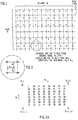
- Referring now to Figure 1, there is shown the position of each pel in a scanned image field of the type specified in ICCTT standards which prescribe the number of pels per inch for each scanned line. In the simplified example shown a scan line consists of 14 pels each identified by an asterisk; the number of scan lines is 8. Those skilled in the art will recognise this to be a rudimentary example of an image field specified by 8 rows and 14 columns i.e. a matrix of 8 x 14. Each pel comprises digital data specifying the grey scale or intensity of a corresponding point in an original image. In the present example each pel is a single
binary digit - Superimposed on the original image field of Figure 1 is a second image field of lower resolution comprising fewer pels than the first image field, each pel of the second image field being identified by a zero (o). The pels shown in the new image field are surrounded by the original image pels, *.
- Referring to Figure 2, it is seen that each new pel T K,L is surrounded by four neighbour pels of the original image matrix: Si,j, Si+1,j, Si,j+,' and Si+1, j+1. The image intensity of the new pel TK,L is a function of the position of the new image pel TK,L within the neighbourhood of original image pels and the intensity of the neighbour pels. The aforementioned prior art algorithm provides a means for calculating the new pel grey scale level as a result of considering the old image neighbourhood pel grey scale level.
- The present embodiment provides for a convenient method, involving only a small amount of computation time, for assigning a new grey scale level to a new image pel given the grey scale levels of the four neighbours of the original image field, and the position of the new pel with respect to the old image neighbours.
- Referring to Figure to 3A, there are shown, as a function of position, representative values of the grey scale of a new image pel derived from the contributions of the members of the old neighbourhood pels of an image to be converted. Figure 3A shows an 8 x 8 matrix of grey scale levels within a neighbourhood of original image pels which are assumed to be 1, 0, 0, 1 in this case. The distance dx represents the 8 different possible positions for a new pel in the horizontal direction within the neighbourhood, after rounding to the nearest 1/8. The distance dy represents the 8 possible rounded positions of a new pel in the vertical direction. It is thus seen that the grey scale level for a new pel within the neighbourhood of Figure 3A may be conveniently identified by its position within the neighbourhood.
- The values of grey scale for a new pel shown in Figure 3A may be rounded for convenience, whereby values of 0.5 or greater are indicated to be binary 1, and values of less than 0.5 are binary 0. Thus, Figure 3A may be modified to that shown in Figure 3B, wherein the grey scale of a new pel within the neighbourhood having four neighbours with grey scale levels of
binary - Figure 3B is considered to be a plane, corresponding to a respective one of the sixteen possible neighbourhood patterns. The grey scale of a new pel within any neighbourhood so represented may be determined by considering its distances dx and dy within the plane, rounded to the nearest 1/8. Thus, by ascertaining the grey scale values of the four pel neighbours, and the position of the new pel within the neighbourhood, a new grey scale may be determined for the new pel within a neighbourhood. The sixteen planes of matrixes representing the sixteen possible neighbourhood configurations for the old image data comprise in the embodiment a look-up table which may be conveniently addressed to read out the grey scale of a new pel of an image matrix having a different resolution to the original image matrix. The look-up table is an addressable memory divided into planes with an 8 x 8 matrix of storage locations in each plane. The planes are addressed by the grey scale levels of the neighbourhood pels of the new pel, and within each plane a particular storage location is addressed by the rounded values dx and dy of the new pel.
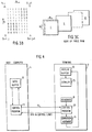
- Referring now to Figure 4 there is shown an overall block diagram of an apparatus for converting matrix image data of a first resolution, sent from a main
frame host computer 11 via abus 15 to aterminal 17, to a different resolution. Thehost computer 11 includes adata buffer 12 andcontrol program 13 for controlling traffic to and from theterminal 17.Terminal 17 similarly includes acontrol program 20 which cooperates with thecontrol program 13 to receive and send data to and from thehost computer 11. - The
terminal 17 is seen to contain akeyboard 19 for permitting user control of the terminal and permitting access to thehost computer 11. Adisplay 23 anddisplay buffer 22 cooperate to present data generated by the keyboard and received from thedata bus 15 for the user's information. - The
terminal 17 includesconversion hardware 21 which will convert image data received from thedata bus 15 from a first field size, containing N1 x M1 pels, to a new image field of N2 x M2 pels. Theconversion hardware 21 is shown more specifically in Figure 5. The system of Figure 5 will be described in general terms with respect to the subsystems I-VI. Following the description of these subsystems, an example of the operation of the apparatus will be described with respect to the flow charts of Figure 6. - Subsystems I and II compute the location of the four neighbour pels of the old image field N x M for each new image pel of the new field N2 x M2. Initially there are stored the old X-size, new X-size, old Y-size, and new Y-size dimensions of the respective image fields in
registers point multipliers random access memories - In subsystem II, the whole number (NEXT PAIR) in
RAM 50 identifies each pair of rows in the old image data which contains neighbours of each new image pel. The fraction AY resulting from the floating point multiplication is also stored in thememory 50 and locates the dy position of the new image pel with respect to the pair of rows identified by the corresponding whole number. - In subsystem I,
memory 40 stores whole numbers shown as TAB# and the corresponding fraction A X. Thememory 40 identifies the pairs of columns of the old image pels which include a new image pel. A X, the corresponding fraction, identifies the dx position between columns of the new image pel. - Thus, subsystem I and II identify the intersecting pairs of rows and columns of the old image data which includes each new image pel.
- The stored whole numbers in
RAM 50, located at addresses inRAM 50 corresponding to the Y address for each new pel, are used to address the stored old image data indata buffer 12, Figure 4, throughshift register 52. The pair of rows identified at each address ofmemory 50 are sequentially inserted throughgates RAMS RAMS address counter 59 andgates shift register 52, until the four neighbours of each new image pel in the pair of rows have been identified and the grey scale contribution of the neighbours to the new image pel contained within the neighbourhood have been identified. Once the pair of old image data rows have been loaded inRAMS address counter 59 addresses each column of old image pels inRAMS memory 40. The output fromRAMS RAMS RAMS - Look-up table IV has associated with each memory location thereof eight binary values to to t7. The eight binary values, each representing a grey scale level of 1 or 0, are applied to a data selector V. Data selector V is under control of a threshold which is a three bit code used to select one of the to to t7 known values. In this way weighting of the grey scale is possible, i.e. the density of
binary 1 values in the resulting image may be varied. In effect, therefore, eight look-up tables are provided corresponding respectively to t0 as the grey scale level in each memory location, t as the grey scale level in each memory location, and so on. For any given image conversion the data selector V will normally select only one of the tables for providing the grey scale levels of the new image pels, according to the density of image required. RAM VI assembles the new image pel grey scale levels until one scan line is produced. - The
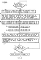
control program 20 provides for the necessary signals to the different circuit components of Figure 5 to effect the foregoing operation. The system will now be described in terms of the actual steps carried on by thecontrol program 20 to convert image data of a first size to a second size. - Referring now to Figures 6a-6d as well as Figure 5, there is shown the flow chart of the steps carried out by the apparatus of Figure 5. The
initial step 65 includes a determination that thekeyboard 19 has selected a request to convert the image data fromdata buffer 12 to an image of a different resolution. The user enters fromkeyboard 19 instep 66 the old and new matrix sizes N1, M and N2' M2 of the image data. Alternately, the manual operator input could be supplanted by suitable programming so that the operation could occur automatically. The sizes of the respective image fields are loaded inshift register 31.Shift register 31 is clocked by pulses from thecontrol programmer 20 to serially produce each of the old image X size (M1), new image X size (M2), old image Y size (N1), and new image Y size (N2) in serial fashion.Gates control program 20 to gate at the appropriate time the respective image dimension to one ofregisters - Once the image sizes reside in the registers,
dividers step 68. The result of the scale factor calculations for each coordinate direction of the matrices are stored inregisters - Address counters 39 and 48 are clocked by the
control program 20 to generate sequentially the address of each of the new image pels of the new matrix. In steps 69-72 the scale factor contained inregister 37 is multiplied by each of the new pel X addresses and the result is a whole number and a fraction, identified as TAB# and A X respectively. The result of the multiplication is stored at an address identified by the newX address counter 39 inRAM 40. As was mentioned previously, at the conclusion of multiplying all of the new pel X addresses by the scale factor,memory 40 will contain TAB# at each new pel X address identifying the pair of columns of the old image data which form neighbours of the new image pel. When theaddress counter 39 has produced an address equal to the new X size as stored inregister 34, the calculation of TAB# and A X coordinates is terminated instep 74. Thus, it is seen thatstep 71 through 74 complete the calculation of TAB# and A X coordinates for each new pel of the new image field and store the result inmemory 40. It will be appreciated that TAB# and ΔX need only be calculated for one line or row of new image pels, as these values will be identical for succeeding rows. - The
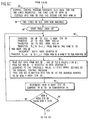
control program 20 provides a subsequent set of control signals for calculating the pairs of rows of old image data, NEXT PAIR, and the A Y coordinate of each new pel within the old image data insteps 75 through 81. The newY address counter 48 is set to 0 instep 76. Each of the subsequent Y addresses produced in response to clock pulses C8 are multiplied by the scale factor contained inregister 47 by floatingpoint multiplier 49. When the newY address counter 48 has incremented to an address having a width of the new Y size contained inregister 45,comparator 51 will terminate the calculation of A Y and the next pair whole number, NEXT PAIR.Memory 50 contains at each new Y address the respective NEXT PAIR rows of old image data which constitute neighbours, and the position within the rows A Y of the new image pel. As for the X direction, it is only necessary to calculate NEXT PAIR and ΔY for one column of the new image pels. - In
step 82, the complete calculation of each new Y address of NEXT PAIR and A Y is completed. - Now that both
memories step 83 identified by referring to the first memory location inmemory 50. The NEXT PAIR identified inmemory 50 is inserted inshift register 52 instep 85.Shift register 52 transmits the address information to theterminal control program 20. Thecontrol program 20 calls forth the proper two consecutive lines of old image data residing in thehost computer system 11 which includes neighbours of the new image pel. Thecontrol program 20 transmits the pair of lines requested intoRAMS RAM 56 contains the first of the pair of lines andRAM 57 contains the second of the pair of lines. Instep 88, the two lines of old image data which contain neighbours of the new image pel are thus available. - The further identification of the neighbours begins in
steps RAM 40 identifies the columns of neighbours stored inRAMS memory 40. The output ofRAMS X address counter 59 is incremented by 1 and the neighbours Si, j+1, and Si+1, j+1 are read from theRAMS - Thus, the four neighbours of a new pel are identified, and applied through gates under control of
control program 20 to the look-up table IV. Look-up table IV is arranged in planes, each of the planes corresponding to the grey scale of the four neighbours. The individual planes of the look-up table 4 are further addressed by ΔX and ΔY which identify the position of each new pel within the neighbourhood of pels addressing the plane. Instep 92, the eight possible binary values produced from the look-up table 4 are selected by data selector V under control of thecontrol program 20. A threshold value is used to discriminate against grey scales above and below a predetermined number, between 0 and 1, which may be set by the operation via the keyboard, a potentiometer or switch, or by a program. The result from the data selector V is one of eight possible grey scale levels which is stored in RAM VI as the grey scale of a pel, RAM VI under control of theaddress counter 39 will for each new X address produced, which has identified the neighbourhood of a pel, store the grey scale level at the new X address. Instep 93, the loading of RAM VI is found to be complete when the new X address counter has an X address which is equal to the new X size. - The
decision block 94 when determining that the last new pel X address has been generated and a corresponding grey scale for a pel at the address identified is stored in RAM VI, indicates that the data inRAMS terminal control program 20 for use by the display buffer. The new address counter is set to 0 instep 98, and then incremented instep 99. Indecision block 100, the new X address is compared with the new X size, and theX address counter 39 is continued to be incremented until thedecision block 100 provides a yes indication. - At this time,
step 101 indicates that all the new data in the RAM VI has been sent to the program controller, and instep 102 the newX address counter 39 is reset to 0. The new Y address counter is incremented and once again compared with the Y dimension of the new image matrix. It there is not an equivalence found, further Y addresses are produced, and the flow chart returns to step 83 to get two more lines of old data for storage inRAMS step 104 for use by the control programmer. - Thus, it is seen that by using a look-up table considerable computation time is saved when image data is produced.
Claims (1)
Applications Claiming Priority (2)
| Application Number | Priority Date | Filing Date | Title |
|---|---|---|---|
| US430228 | 1982-09-30 | ||
| US06/430,228 US4528693A (en) | 1982-09-30 | 1982-09-30 | Apparatus and method for scaling facsimile image data |
Publications (2)
| Publication Number | Publication Date |
|---|---|
| EP0105707A1 true EP0105707A1 (en) | 1984-04-18 |
| EP0105707B1 EP0105707B1 (en) | 1987-03-11 |
Family
ID=23706623
Family Applications (1)
| Application Number | Title | Priority Date | Filing Date |
|---|---|---|---|
| EP83305821A Expired EP0105707B1 (en) | 1982-09-30 | 1983-09-28 | Apparatus for scaling fascimile image data |
Country Status (5)
| Country | Link |
|---|---|
| US (1) | US4528693A (en) |
| EP (1) | EP0105707B1 (en) |
| JP (1) | JPH0618432B2 (en) |
| CA (1) | CA1204852A (en) |
| DE (1) | DE3370214D1 (en) |
Cited By (17)
| Publication number | Priority date | Publication date | Assignee | Title |
|---|---|---|---|---|
| EP0131321A2 (en) * | 1983-06-15 | 1985-01-16 | Philips Electronics Uk Limited | Video display system |
| EP0167838A2 (en) * | 1984-07-06 | 1986-01-15 | MILES INC. (an Indiana corporation) | Method for producing a scaleable typeface data |
| EP0182237A2 (en) * | 1984-11-19 | 1986-05-28 | General Electric Company | Method and means for altering the spatial characteristics of a digital image |
| EP0183201A2 (en) * | 1984-11-26 | 1986-06-04 | General Electric Company | Apparatus and means for altering spatial characteristics of a digital image by polynomial interpretation using sets of arithmetic processors |
| EP0194066A2 (en) * | 1985-03-07 | 1986-09-10 | Sony Corporation | Video signal processing |
| EP0216928A1 (en) * | 1984-12-06 | 1987-04-08 | Dainippon Screen Mfg. Co., Ltd. | Method and apparatus for compressing image data |
| WO1988006769A1 (en) * | 1987-03-02 | 1988-09-07 | Digital Equipment Corporation | Fast bitonal to gray scale image scaling |
| EP0388089A2 (en) * | 1989-03-15 | 1990-09-19 | International Business Machines Corporation | Image processing apparatus |
| EP0422793A2 (en) * | 1989-10-13 | 1991-04-17 | Hewlett-Packard Company | Graphics scaling method for high resolution printers |
| WO1991006065A2 (en) * | 1989-10-10 | 1991-05-02 | Unisys Corporation | Image data processor system |
| EP0454088A2 (en) * | 1990-04-25 | 1991-10-30 | Canon Kabushiki Kaisha | Image processing apparatus |
| US5140444A (en) * | 1989-10-10 | 1992-08-18 | Unisys Corporation | Image data processor |
| EP0521556A2 (en) * | 1991-07-05 | 1993-01-07 | Koninklijke Philips Electronics N.V. | Data processing system with means for display of reduced images and method for the reduction of images |
| US5305398A (en) * | 1989-10-10 | 1994-04-19 | Unisys Corporation | Method and apparatus for scaling image data |
| WO1994027278A1 (en) * | 1993-05-10 | 1994-11-24 | Apple Computer, Inc. | A windowing system with independent windows of arbitrary resolution for display on multiple devices of arbitrary resolution |
| WO1996005692A1 (en) * | 1994-08-09 | 1996-02-22 | Infotronic S.P.A. | Method of processing video bitonal images |
| EP0803840A1 (en) * | 1996-04-25 | 1997-10-29 | Hewlett-Packard Company | Versatile scaling of drawings |
Families Citing this family (56)
| Publication number | Priority date | Publication date | Assignee | Title |
|---|---|---|---|---|
| US5666444A (en) * | 1982-04-06 | 1997-09-09 | Canon Kabushiki Kaisha | Image processing apparatus |
| GB2120896B (en) * | 1982-04-06 | 1987-01-28 | Canon Kk | Half-tone facsimile system |
| US4610026A (en) * | 1982-04-30 | 1986-09-02 | Hitachi, Ltd. | Method of and apparatus for enlarging/reducing two-dimensional images |
| JPS59216190A (en) * | 1983-05-24 | 1984-12-06 | 株式会社日立製作所 | Display control system |
| JPS6057457A (en) * | 1983-09-07 | 1985-04-03 | Ricoh Co Ltd | Dma device |
| JPS6085678A (en) * | 1983-10-17 | 1985-05-15 | Canon Inc | Picture processing system |
| US4712140A (en) * | 1983-12-30 | 1987-12-08 | International Business Machines Corporation | Image reduction method |
| JPS60208164A (en) * | 1984-03-30 | 1985-10-19 | Canon Inc | Recorder |
| US5255331A (en) * | 1984-06-20 | 1993-10-19 | The Governor And Company Of The Bank Of England | Production of an image model and inspection of a pixel representation of an image |
| US4628534A (en) * | 1984-07-06 | 1986-12-09 | Honeywell Information Systems Inc. | Method for changing the resolution of compressed image data |
| US4630307A (en) * | 1984-09-10 | 1986-12-16 | Eastman Kodak Company | Signal processing method and apparatus for sampled image signals |
| US4733304A (en) * | 1984-10-11 | 1988-03-22 | Dai Nippon Insatsu Kabushiki Kaisha | Method of processing picture data for printing process and device implementing the same |
| US4692810A (en) * | 1985-05-22 | 1987-09-08 | Toyo Seikan Kaisha, Ltd. | Process for printed draw-formed body, and container formed by this process |
| JPS623372A (en) * | 1985-06-27 | 1987-01-09 | インタ−ナショナル ビジネス マシ−ンズ コ−ポレ−ション | Image converter |
| DE3789461D1 (en) * | 1986-01-22 | 1994-05-05 | Konishiroku Photo Ind | Image processing system with the ability to enlarge and reduce operation. |
| US4885576A (en) * | 1986-04-02 | 1989-12-05 | International Business Machines Corporation | Soft copy display of facsimile images |
| US4833531A (en) * | 1986-04-21 | 1989-05-23 | Konishiroku Photo Industry Co., Ltd. | Technique for interpolating a color image for image enlargement or reduction based on look-up tables stored in memory |
| DE3687460T2 (en) * | 1986-06-26 | 1993-04-29 | Wang Laboratories | RESOLUTION CONVERSION OF POINT ORGANIZED IMAGES USING FAILURE VALUE FORMATION. |
| US5029017A (en) * | 1986-10-08 | 1991-07-02 | Konishiroku Photo Industry Co., Ltd. | Image processing apparatus capable of enlarging/reducing apparatus |
| US4816914A (en) * | 1987-01-07 | 1989-03-28 | Pictel Corporation | Method and apparatus for efficiently encoding and decoding image sequences |
| USH996H (en) | 1987-01-20 | 1991-11-05 | Recognition Equipment Incorporated | High resolution page image display system |
| US5113494A (en) * | 1987-02-27 | 1992-05-12 | Eastman Kodak Company | High speed raster image processor particularly suited for use in an image management system |
| US4849810A (en) * | 1987-06-02 | 1989-07-18 | Picturetel Corporation | Hierarchial encoding method and apparatus for efficiently communicating image sequences |
| FR2620544B1 (en) * | 1987-09-16 | 1994-02-11 | Commissariat A Energie Atomique | INTERPOLATION PROCESS |
| US5119435A (en) * | 1987-09-21 | 1992-06-02 | Kulicke And Soffa Industries, Inc. | Pattern recognition apparatus and method |
| US4853968A (en) * | 1987-09-21 | 1989-08-01 | Kulicke & Soffa Industries, Inc. | Pattern recognition apparatus and method |
| US4872064A (en) * | 1987-10-19 | 1989-10-03 | Interand Corporation | System for selective scaling of digital video images |
| JPH0795345B2 (en) * | 1988-04-21 | 1995-10-11 | 株式会社イーゼル | Image processing method |
| US5355447A (en) * | 1988-05-27 | 1994-10-11 | Wang Laboratories, Inc. | Method for color image reduction based upon determination of color components of pixels in neighboring blocks |
| US4952921A (en) * | 1988-06-09 | 1990-08-28 | Rockwell International Corporation | Graphic dot flare apparatus |
| US5067019A (en) * | 1989-03-31 | 1991-11-19 | The United States Of America As Represented By The Administrator Of The National Aeronautics And Space Administration | Programmable remapper for image processing |
| US4970604A (en) * | 1989-04-14 | 1990-11-13 | Coueignoux Philippe J | Screen display enhancing system |
| US7382929B2 (en) | 1989-05-22 | 2008-06-03 | Pixel Instruments Corporation | Spatial scan replication circuit |
| US4977602A (en) * | 1989-11-20 | 1990-12-11 | Eastman Kodak Company | Character normalization using an elliptical sampling window for optical character recognition |
| US5410615A (en) * | 1990-09-25 | 1995-04-25 | Xerox Corporation | Bitmap image resolution converter compensating for write-white xerographic laser printing |
| US5282057A (en) * | 1990-04-23 | 1994-01-25 | Xerox Corporation | Bit-map image resolution converter |
| US5227893A (en) * | 1990-10-31 | 1993-07-13 | International Business Machines Corporation | Pseudo-bar code control of image transmission |
| US5140431A (en) * | 1990-12-31 | 1992-08-18 | E. I. Du Pont De Nemours And Company | Digital electronic system for halftone printing |
| US5335295A (en) * | 1991-05-08 | 1994-08-02 | International Business Machines Corporation | System and method for scaling a digital image |
| US5185817A (en) * | 1991-05-14 | 1993-02-09 | Hewlett-Packard Company | Image processor |
| JPH0817440B2 (en) * | 1991-08-29 | 1996-02-21 | 村田機械株式会社 | Fax machine |
| US5257324A (en) * | 1991-11-01 | 1993-10-26 | The United States Of America As Represented By The Secretary Of The Navy | Zero-time-delay video processor circuit |
| US6118429A (en) | 1993-09-30 | 2000-09-12 | Hitachi, Ltd. | Liquid crystal display system capable of reducing and enlarging resolution of input display data |
| US5528704A (en) * | 1993-11-15 | 1996-06-18 | Xerox Corporation | Image resolution conversion using a plurality of image registrations |
| KR0135846B1 (en) * | 1994-02-02 | 1998-06-15 | 김광호 | Look up table device |
| US5784047A (en) * | 1995-04-28 | 1998-07-21 | Intel Corporation | Method and apparatus for a display scaler |
| US6717695B1 (en) * | 1997-03-27 | 2004-04-06 | OCé PRINTING SYSTEMS GMBH | Method and circuit for the production of compressed or expanded images, and printer with such circuit |
| US6151025A (en) * | 1997-05-07 | 2000-11-21 | Hewlett-Packard Company | Method and apparatus for complexity reduction on two-dimensional convolutions for image processing |
| US6498868B1 (en) * | 1998-06-11 | 2002-12-24 | Xerox Corporation | Image scaling using pattern matching to select among scaling algorithms |
| US6496206B1 (en) | 1998-06-29 | 2002-12-17 | Scansoft, Inc. | Displaying thumbnail images of document pages in an electronic folder |
| JP2000350022A (en) * | 1999-03-30 | 2000-12-15 | Canon Inc | Method and device for image processing |
| FR2791848B1 (en) * | 1999-03-31 | 2001-06-15 | Sagem | DEVICE AND METHOD FOR GENERATING A MODIFIED IMAGE BY PROCESSING A SOURCE IMAGE |
| JP2000339450A (en) * | 1999-05-26 | 2000-12-08 | Sony Corp | Picture processing method and picture processor |
| US6927780B2 (en) * | 2002-01-14 | 2005-08-09 | Seiko Epson Corporation | Fast text/graphics resolution improvement with chain-code table look-up |
| TWI247245B (en) * | 2003-09-16 | 2006-01-11 | Realtek Semiconductor Corp | A scaling device and method capable of controlling data input and/or output capacity |
| WO2020041930A1 (en) * | 2018-08-27 | 2020-03-05 | SZ DJI Technology Co., Ltd. | Image processing and presentation |
Citations (5)
| Publication number | Priority date | Publication date | Assignee | Title |
|---|---|---|---|---|
| US3976982A (en) * | 1975-05-12 | 1976-08-24 | International Business Machines Corporation | Apparatus for image manipulation |
| US4090188A (en) * | 1975-07-07 | 1978-05-16 | Fuji Xerox Co., Ltd. | Dot matrix converter |
| DE2835689A1 (en) * | 1977-08-31 | 1979-03-15 | Ibm | ARRANGEMENT FOR CHANGING THE RESOLUTION FOR IMAGE DATA ACQUISITION AND TRANSFER |
| EP0016299A1 (en) * | 1979-03-23 | 1980-10-01 | International Business Machines Corporation | System for and method of reproducing an image |
| US4381547A (en) * | 1979-11-28 | 1983-04-26 | Ricoh Co., Ltd. | Picture deforming process |
Family Cites Families (2)
| Publication number | Priority date | Publication date | Assignee | Title |
|---|---|---|---|---|
| US4193092A (en) * | 1978-06-21 | 1980-03-11 | Xerox Corporation | Image interpolation system |
| JPS579166A (en) * | 1980-06-19 | 1982-01-18 | Ricoh Co Ltd | Picture shrinking device |
-
1982
- 1982-09-30 US US06/430,228 patent/US4528693A/en not_active Expired - Lifetime
-
1983
- 1983-09-19 JP JP58171418A patent/JPH0618432B2/en not_active Expired - Lifetime
- 1983-09-23 CA CA000437405A patent/CA1204852A/en not_active Expired
- 1983-09-28 EP EP83305821A patent/EP0105707B1/en not_active Expired
- 1983-09-28 DE DE8383305821T patent/DE3370214D1/en not_active Expired
Patent Citations (5)
| Publication number | Priority date | Publication date | Assignee | Title |
|---|---|---|---|---|
| US3976982A (en) * | 1975-05-12 | 1976-08-24 | International Business Machines Corporation | Apparatus for image manipulation |
| US4090188A (en) * | 1975-07-07 | 1978-05-16 | Fuji Xerox Co., Ltd. | Dot matrix converter |
| DE2835689A1 (en) * | 1977-08-31 | 1979-03-15 | Ibm | ARRANGEMENT FOR CHANGING THE RESOLUTION FOR IMAGE DATA ACQUISITION AND TRANSFER |
| EP0016299A1 (en) * | 1979-03-23 | 1980-10-01 | International Business Machines Corporation | System for and method of reproducing an image |
| US4381547A (en) * | 1979-11-28 | 1983-04-26 | Ricoh Co., Ltd. | Picture deforming process |
Cited By (30)
| Publication number | Priority date | Publication date | Assignee | Title |
|---|---|---|---|---|
| EP0131321A2 (en) * | 1983-06-15 | 1985-01-16 | Philips Electronics Uk Limited | Video display system |
| EP0131321A3 (en) * | 1983-06-15 | 1990-06-13 | Philips Electronic And Associated Industries Limited | Video display system |
| EP0167838A3 (en) * | 1984-07-06 | 1988-06-08 | Compugraphic Corporation | Method for producing a scaleable typeface data |
| EP0167838A2 (en) * | 1984-07-06 | 1986-01-15 | MILES INC. (an Indiana corporation) | Method for producing a scaleable typeface data |
| EP0182237A2 (en) * | 1984-11-19 | 1986-05-28 | General Electric Company | Method and means for altering the spatial characteristics of a digital image |
| EP0182237A3 (en) * | 1984-11-19 | 1989-03-29 | General Electric Company | Method and means for altering the spatial characteristics of a digital image |
| EP0183201A3 (en) * | 1984-11-26 | 1989-03-22 | General Electric Company | Apparatus and means for altering spatial characteristics of a digital image by polynomial interpretation using sets of arithmetic processors |
| EP0183201A2 (en) * | 1984-11-26 | 1986-06-04 | General Electric Company | Apparatus and means for altering spatial characteristics of a digital image by polynomial interpretation using sets of arithmetic processors |
| EP0216928A1 (en) * | 1984-12-06 | 1987-04-08 | Dainippon Screen Mfg. Co., Ltd. | Method and apparatus for compressing image data |
| EP0216928A4 (en) * | 1984-12-06 | 1989-05-11 | Dainippon Screen Mfg | Method and apparatus for compressing image data. |
| EP0194066A3 (en) * | 1985-03-07 | 1990-03-14 | Sony Corporation | Video signal processing |
| EP0194066A2 (en) * | 1985-03-07 | 1986-09-10 | Sony Corporation | Video signal processing |
| WO1988006769A1 (en) * | 1987-03-02 | 1988-09-07 | Digital Equipment Corporation | Fast bitonal to gray scale image scaling |
| EP0388089A3 (en) * | 1989-03-15 | 1992-12-02 | International Business Machines Corporation | Image processing apparatus |
| EP0388089A2 (en) * | 1989-03-15 | 1990-09-19 | International Business Machines Corporation | Image processing apparatus |
| WO1991006065A2 (en) * | 1989-10-10 | 1991-05-02 | Unisys Corporation | Image data processor system |
| US5305398A (en) * | 1989-10-10 | 1994-04-19 | Unisys Corporation | Method and apparatus for scaling image data |
| WO1991006065A3 (en) * | 1989-10-10 | 1992-01-09 | Unisys Corp | Image data processor system |
| US5140444A (en) * | 1989-10-10 | 1992-08-18 | Unisys Corporation | Image data processor |
| EP0422793A2 (en) * | 1989-10-13 | 1991-04-17 | Hewlett-Packard Company | Graphics scaling method for high resolution printers |
| EP0422793A3 (en) * | 1989-10-13 | 1992-12-30 | Hewlett-Packard Company | Graphics scaling method for high resolution printers |
| EP0454088A2 (en) * | 1990-04-25 | 1991-10-30 | Canon Kabushiki Kaisha | Image processing apparatus |
| EP0454088B1 (en) * | 1990-04-25 | 1998-07-01 | Canon Kabushiki Kaisha | Image processing apparatus |
| EP0521556A2 (en) * | 1991-07-05 | 1993-01-07 | Koninklijke Philips Electronics N.V. | Data processing system with means for display of reduced images and method for the reduction of images |
| EP0521556A3 (en) * | 1991-07-05 | 1993-12-08 | Koninkl Philips Electronics Nv | Data processing system with means for display of reduced images and method for the reduction of images |
| US6216144B1 (en) | 1991-07-05 | 2001-04-10 | U.S. Philips Corporation | Data processing system with means for display of reduced images and method for the reduction of images |
| WO1994027278A1 (en) * | 1993-05-10 | 1994-11-24 | Apple Computer, Inc. | A windowing system with independent windows of arbitrary resolution for display on multiple devices of arbitrary resolution |
| US5517209A (en) * | 1993-05-10 | 1996-05-14 | Apple Computer, Inc. | Windowing system with independent windows of arbitrary resolution for display on multiple devices of arbitrary resolution |
| WO1996005692A1 (en) * | 1994-08-09 | 1996-02-22 | Infotronic S.P.A. | Method of processing video bitonal images |
| EP0803840A1 (en) * | 1996-04-25 | 1997-10-29 | Hewlett-Packard Company | Versatile scaling of drawings |
Also Published As
| Publication number | Publication date |
|---|---|
| JPS5975758A (en) | 1984-04-28 |
| CA1204852A (en) | 1986-05-20 |
| US4528693A (en) | 1985-07-09 |
| DE3370214D1 (en) | 1987-04-16 |
| EP0105707B1 (en) | 1987-03-11 |
| JPH0618432B2 (en) | 1994-03-09 |
Similar Documents
| Publication | Publication Date | Title |
|---|---|---|
| EP0105707B1 (en) | Apparatus for scaling fascimile image data | |
| US4723297A (en) | Method for automatic correction of character skew in the acquisition of a text original in the form of digital scan results | |
| US4577235A (en) | Text/continuous tone image decision processor | |
| US4578812A (en) | Digital image processing by hardware using cubic convolution interpolation | |
| US4697178A (en) | Computer graphics system for real-time calculation and display of the perspective view of three-dimensional scenes | |
| CA1209244A (en) | Compaction and decompaction of non-coded information bearing signals | |
| US6172773B1 (en) | Void and cluster apparatus and method for generating dither templates | |
| US4905164A (en) | Method for modulating color for effecting color cell texture | |
| EP0165045B1 (en) | Document scanning system for enhancing information | |
| EP0272655A2 (en) | Method and apparatus for generating look-up table data | |
| EP0573174B1 (en) | Display control apparatus and method | |
| EP0043069A1 (en) | Segmentation apparatus and method for character recognition | |
| EP0513516A2 (en) | Apparatus for and method of reducing a digital image | |
| US5201030A (en) | Method and apparatus for dithering graphic images | |
| EP0154449B1 (en) | Real time character thinning system | |
| EP0063865B1 (en) | Digital scan converter with randomized decay function | |
| EP0389811A2 (en) | Image data processing system with adaptive binary quantization | |
| EP0593304A2 (en) | Apparatus and method for generating void and cluster dither templates | |
| US4607340A (en) | Line smoothing circuit for graphic display units | |
| EP0283627A2 (en) | Apparatus and method for storing and transmitting images represented by logic signals | |
| US5371515A (en) | Method and apparatus for non-linear dithering of digital images | |
| KR970705030A (en) | Improved picture quality for raster displays | |
| US4977602A (en) | Character normalization using an elliptical sampling window for optical character recognition | |
| EP0160363A2 (en) | Binarizing system of picture image signals | |
| US4736248A (en) | Method and device for generating intermediate picture signals from reference picture signals having a reduced picture frequency |
Legal Events
| Date | Code | Title | Description |
|---|---|---|---|
| PUAI | Public reference made under article 153(3) epc to a published international application that has entered the european phase |
Free format text: ORIGINAL CODE: 0009012 |
|
| AK | Designated contracting states |
Designated state(s): DE FR GB IT NL |
|
| 17P | Request for examination filed |
Effective date: 19840724 |
|
| GRAA | (expected) grant |
Free format text: ORIGINAL CODE: 0009210 |
|
| AK | Designated contracting states |
Kind code of ref document: B1 Designated state(s): DE FR GB IT NL |
|
| REF | Corresponds to: |
Ref document number: 3370214 Country of ref document: DE Date of ref document: 19870416 |
|
| ET | Fr: translation filed | ||
| ITF | It: translation for a ep patent filed |
Owner name: IBM - DR. ARRABITO MICHELANGELO |
|
| PLBE | No opposition filed within time limit |
Free format text: ORIGINAL CODE: 0009261 |
|
| STAA | Information on the status of an ep patent application or granted ep patent |
Free format text: STATUS: NO OPPOSITION FILED WITHIN TIME LIMIT |
|
| 26N | No opposition filed | ||
| ITTA | It: last paid annual fee | ||
| PGFP | Annual fee paid to national office [announced via postgrant information from national office to epo] |
Ref country code: FR Payment date: 19950911 Year of fee payment: 13 |
|
| PGFP | Annual fee paid to national office [announced via postgrant information from national office to epo] |
Ref country code: NL Payment date: 19950927 Year of fee payment: 13 |
|
| PG25 | Lapsed in a contracting state [announced via postgrant information from national office to epo] |
Ref country code: FR Effective date: 19960930 |
|
| PG25 | Lapsed in a contracting state [announced via postgrant information from national office to epo] |
Ref country code: NL Effective date: 19970401 |
|
| NLV4 | Nl: lapsed or anulled due to non-payment of the annual fee |
Effective date: 19970401 |
|
| REG | Reference to a national code |
Ref country code: FR Ref legal event code: ST |
|
| REG | Reference to a national code |
Ref country code: FR Ref legal event code: ST |
|
| REG | Reference to a national code |
Ref country code: GB Ref legal event code: IF02 |
|
| PGFP | Annual fee paid to national office [announced via postgrant information from national office to epo] |
Ref country code: GB Payment date: 20020902 Year of fee payment: 20 |
|
| PGFP | Annual fee paid to national office [announced via postgrant information from national office to epo] |
Ref country code: DE Payment date: 20021002 Year of fee payment: 20 |
|
| PG25 | Lapsed in a contracting state [announced via postgrant information from national office to epo] |
Ref country code: GB Free format text: LAPSE BECAUSE OF EXPIRATION OF PROTECTION Effective date: 20030927 |
|
| REG | Reference to a national code |
Ref country code: GB Ref legal event code: PE20 |