EP0108388A2 - Paper transporting device for endless paper printing installations with a single paper pressing roll - Google Patents
Paper transporting device for endless paper printing installations with a single paper pressing roll Download PDFInfo
- Publication number
- EP0108388A2 EP0108388A2 EP83110925A EP83110925A EP0108388A2 EP 0108388 A2 EP0108388 A2 EP 0108388A2 EP 83110925 A EP83110925 A EP 83110925A EP 83110925 A EP83110925 A EP 83110925A EP 0108388 A2 EP0108388 A2 EP 0108388A2
- Authority
- EP
- European Patent Office
- Prior art keywords
- paper
- roller
- pressure roller
- transport device
- platen
- Prior art date
- Legal status (The legal status is an assumption and is not a legal conclusion. Google has not performed a legal analysis and makes no representation as to the accuracy of the status listed.)
- Granted
Links
Images


Classifications
-
- B—PERFORMING OPERATIONS; TRANSPORTING
- B41—PRINTING; LINING MACHINES; TYPEWRITERS; STAMPS
- B41J—TYPEWRITERS; SELECTIVE PRINTING MECHANISMS, i.e. MECHANISMS PRINTING OTHERWISE THAN FROM A FORME; CORRECTION OF TYPOGRAPHICAL ERRORS
- B41J15/00—Devices or arrangements of selective printing mechanisms, e.g. ink-jet printers or thermal printers, specially adapted for supporting or handling copy material in continuous form, e.g. webs
- B41J15/18—Multiple web-feeding apparatus
Definitions
- the invention relates to a paper transport device according to the preamble of patent claim 1.
- German Patent 3,014,340 a device for pressing and lifting a paper transport shaft of a typewriter is known, in which the paper transport shaft mounted on one side is pivoted away from the platen roller by means of a latching device for the purpose of transporting perforated paper.
- the transport shaft with the single paper transport roller arranged thereon is in contact with the paper roller.
- the paper transport roller and the platen roller are operated at the same peripheral speed.
- the object of the invention is a paper transport device for printing devices with single and multiple layers To provide continuous paper that ensures exact paper transport in the area of the impression point and that does not move the individual layers when using multi-layer paper.
- the fact that the paper pressure roller is driven by a motor in such a way that the peripheral speed of the pressure roller has a propulsion relative to the peripheral speed of the paper roller results in connection with a paper guide channel tangentially flushing away from the paper roller and a device upstream of the paper guide channel for generating a pretension between the paper and paper roller a paper transport device with which multilayer continuous paper can also be transported without interfering displacements between the layers.
- the entire paper feed device is extremely simple, but there is still an exact guidance of the paper.
- the tension compensation device is designed according to a further development of the invention as a paper guide saddle with a broad paper support surface, which is supported on a spring-mounted wire bracket, this floating bearing leads to an exact entry of the multilayer paper into the paper feed.
- the tension compensation device can adapt to the position of the paper roll above difficulties.
- the broad contact surface of the saddle has the advantage that it brings the force of the compensation bracket to the paper web in the same way as a glider. The- This gentle redirection helps to soothe the paper and reduces the noise of the printer.
- the saddle guides the paper over a long length, making it easier to hold the individual layers together. This is especially true when using carbon paper inserts.
- the lateral guide elements of the tension compensation device are designed as elements which can be locked with the paper guide saddle, the paper guide saddle can easily be adapted to different paper widths, for which purpose paper support surfaces of different widths can also be arranged on a paper guide saddle.
- a particularly simple guide for the paper transport shaft results from a frame-supported spring wire lever, one arm of which supports the movably mounted end of the paper transport shaft and the other arm of which is connected to the swivel lever.
- This frame-supported spring wire lever can be combined with a spring clip in the paper feed, which detects the presence of paper, and the positions of both levers can be scanned using a common scanning device.
- the paper feed device can advantageously be scanned both with regard to the pivoting state of the paper pressure roller and with regard to the presence of paper in the paper feed device. This is particularly necessary if the paper feed device is used as part of a communication device, e.g. represents a teletype machine is used.
- the multilayer continuous paper is fed to the paper guide channel of the teleprinter via a tension compensation device 3 described later, which consists of a spring-mounted wire bracket with a paper guide saddle floating thereon.
- This paper guide channel contains a guide plate 5, which is tangentially aligned away from the motor-driven platen roller 4, with a paper transport shaft 7 mounted on one side below the writing point and provided with only one pressure roller, and one adjoining the paper transport shaft 7 the resilient paper pressure bar 8, which extends over the entire width of the paper roller.
- a writing head 9 with a drive device is moved line by line along the recording medium stretched over the writing roller 4.
- the paper transport described in more detail below is brought about by the motor-driven platen roller 4 in connection with the likewise motor-driven paper transport shaft by friction.
- the paper described is supported by a tray 6 in the lid of the housing 2.
- the core of the paper transport device consists of the paper transport shaft 7, which is motor-driven via a gear 11 with the platen roller 4 and is fixedly mounted on one side in the frame 2, and which is guided at its other end by a spring bracket 12 fixed to the frame becomes.
- a Paper feed shaft 7 there is a Jetan horrrolle 13 having a narrow relative to the width of the paper roll 32 has the cylindrical portion into contact with the - represents paper.
- the cylindrical region 32 tapers on both sides, and the conical side elements can also have a barrel shape.
- the angle ⁇ of the paper pressure bar 8 to the tangent to the platen roller 4 and the distance A between the paper pressure roller 13 and the paper pressure bar 8 on the circumference of the platen roller 4 are chosen so that the buckling resistance of light papers is sufficient to the pressure force F1 of the paper pressure bar 8 without jamming overcome.
- the diameter D of the paper pressure roller 13 is dimensioned correspondingly large.
- the paper pressure roller 13 itself is below that limited by the paper pressure roller 8
- the writing point of the printing device 90 is arranged so that the largest possible wrap angle ⁇ of the multilayer continuous paper 10 on the platen roller 4 results.
- the large wrap angle shown here of approximately 90 ° on the platen roller 4 permits a wide spread of the coefficient of friction of the platen roller covering.
- the central position of the barrel-shaped paper pressure roller 13 in a recess 15 of the paper guide plate 5 results in connection with a lateral paper guide 16 or with the guide of the tension compensation device 3.
- "Handlebar effect” which ensures the transport of the multi-layer continuous paper 10 without the layers being distorted.
- the speed ratio of platen roller 4 to paper pressure roller 13 is selected so that a small advance of 0.5% to 5% occurs on the pressure roller 13.
- This propulsion due to the different peripheral speeds of the platen roller 4 and the paper pressure roller 13, limits the formation of loops on the supply roller 1 and improves the wrap on the platen roller 4 in the case of multilayer paper.
- the size of the drive depends on the friction pairing of the pressure roller and paper and may also be greater than 5%.
- the pressure force F2 on the paper pressure roller 13 is generated by a frame-supported spring clip 12 made of wire via its torsion.
- the pressing force F2 can be very small since the rotary movement of the paper pressure roller 13 is generated by means of a gear stage of the platen roller 4 and is therefore independent of friction.
- the paper transport device consists of the platen roller 4, which is rotatably mounted in the frame 2 in a motor-driven manner.
- the paper transport shaft 7 connected to the platen roller 11 with the roller mounted thereon and with the paper transport shaft 7 firmly connected, barrel-shaped paper pressure roller 13.
- the paper transport shaft 7 with the paper pressure roller 13 is located at the end of the paper guide area 5 delimited by the paper guide plate and is rotatable on one side in the frame 2 and with its other end according to the direction of the arrow in an eyelet 17 of an arm of the rack-supported spring bracket 12 mounted.
- the paper pressure roller 13 can be pressed more or less strongly against the paper roller 4 or the paper 10 lying therebetween via the spring clip 12.
- a total swiveling of the paper pressure roller 13 is also possible for insertion and adjustment.
- For this purpose is fixed to the frame of the lead '18 mounted spring clip with its other arm is operatively connected to a pivot lever 19 which in turn is rotatably mounted about an axis 20th
- the swivel lever consists of a grip piece 21 with an attachment piece 22 arranged below the grip piece. In the illustrated pressed-on state of the paper pressure roller 13, one end of this spring piece rests against this attachment piece 22 under the torsional action of the spring clip 12. By pivoting the pivot lever 19 in accordance with the direction of the arrow shown, the paper roll of the platen roller 4 can be pivoted away.
- a scanning spring clip 23 is provided to detect the presence of paper in the paper guide.
- the scanning spring clip 23 engages with its loop-shaped bent scanning end 24 through an opening in the paper guide plate 5 and is supported on the platen roller 4.
- the scanning spring clip 23 is bent several times and with its outer end in a recess 25 of the Pa pier guide plates 5 stored stationary.
- the scanning spring clip 23 is guided by a guide piece 26 of the pivot lever 19 which is arranged eccentrically with respect to the axis of rotation of the part 20, the part of the scanning spring clip 23 lying opposite the scanning end having a U-shaped course and abutting an electrical scanning device 27 designed as a switch.
- the interaction of the scanning spring clip 23 with the electrical scanning device 27 and the spring clip 12 is as follows:
- the scanning end 24 and thus the scanning spring clip 23 are lifted off the platen roller 4.
- the swivel lever 19 is in the basic position shown with the paper pressure roller 13 pressed on. telsexual of the scanning bracket.
- the electrical scanning device is thus actuated and a switch contained in the electrical scanning device is thus opened.
- the opened switch interrupts a circuit consisting of a current source 29 and a warning lamp 30, so that the warning lamp 30 is extinguished.
- the electrical scanning device 27 can also be connected to a central microprocessor of the printing device which controls the operating states (on-off) as a function of the scanning device.
- the scanning spring clip rests on the platen roller S due to its spring behavior in accordance with the direction of the arrow shown.
- the button 28 is also moved in the direction of the arrow and the warning circuit is closed.
- the warning lamp 30 lights up.
- This warning lamp also lights up when the pivot lever 19 is moved in the direction of the arrow to pivot the paper transport shaft.
- the scanning spring clip 23 is pivoted through the angle 31 via the eccentric guide piece 2. 6, which in turn closes the warning circuit and thus lights up the warning lamp 30. It is thus possible to use the electrical scanning device 27 both for scanning the paper feed device on the paper end and for scanning the pivoted state of the paper pressure roller.
- the tension compensation device 3 (FIG. 3) provided for generating a pretension of the multi-layer continuous paper 10 between the supply roll 1 and the platen roller 4 consists of a spring clip 43 which is spring-mounted on an axis 41 by means of loops 42 and on which a paper guide clip 45 having lateral guide elements 44 is also included wider paper support surface 46 is floating, ie laterally displaceable, stored.
- the paper support surface 47 guides and centers the multilayer continuous paper 47.
- the lateral guides 44 are connected to the paper support surfaces 46/1 and 46/2 in an exchangeable manner via latching elements.
- the paper guide saddle is tubular in accordance with the sectional view of Figure 5 and has a plurality of paper support surfaces 46/1 and 46/2.
- the corresponding adjustment of the paper guide saddle provided with two paper support surfaces 46/1 and 46/2 to the corresponding width of the multi-layer continuous paper is carried out by simply pivoting the paper guide saddle 45 on the wire bracket 43.
- the wire bracket 43 slides in an elongated hole guide 49 and the axis length changes 4 from position 50 to the bottom sition 51 and vice versa. This means that the setting is made by simply swiveling the paper guide saddle 45 through 180 °.
- the paper 47 resting on the paper guide saddle 45 ensures, by its own weight or by the pressing force of the spring 42, that the paper guide saddle of the company cannot pivot.
- central guide 49 for the wire bracket 43 is designed in a star shape as shown in FIG. 6, then three paper support surfaces 46/3, 46/4 and 46/5 of different widths can be arranged on the circumference of the paper guide saddle 44.
- the wire bracket is moved to position 49/1 or 49/2 or 49/3.
- a particularly advantageous and simple embodiment of the paper feed device is obtained if, as shown in FIG. 7, the motor-driven paper pressure roller 13 is arranged above the writing point, ie behind the writing point in the feed direction. This results in a particularly simple wrapping with even contact of the paper 10 on the platen. Due to the large wrap, the pressure force of the pressure roller 13 can be reduced even further, so that even the thinnest papers with corresponding carbon intermediate layers can be transported through the paper transport device without any traces of pressure points.
- the tension compensation device 3 in connection with a funnel-shaped paper feed channel made from the lateral guide plate 5 with a counter plate 5/1, which can consist, for example, of a housing wall, leads to a particularly gentle treatment of the multi-layer paper.
- the curvature of the multi-layer recording medium pre-embossed by the paper roll 1 is passed through during the passage maintain the paper feed device and thus through the entire printing device.
- This uniform guidance of the multilayer continuous paper through the entire printing device results in a particularly good adjustment of the individual layers of the multilayer continuous paper to one another and thus a completely uniform line position.
- the entire printing device can be constructed in a particularly compact manner.
- a tear-off edge 32 can be arranged above the paper pressure roller 13, which, due to its proximity to the paper pressure roller 13, enables the printed continuous paper to be torn off particularly easily and precisely.
Abstract
Die Papiertransportvorrichtung für Druckeinrichtungen mit Endlospapier besteht aus einer motorisch angetriebenen Schreibwalze (4) und einer einzigen, in etwa der Mitte der Papierwalze elastisch abschwenkbar an der Schreibwalze (4) anliegenden Papierandruckrolle (13). Die Papierandruckrolle (13) wird motorisch derart angetrieben, daß die Umfangsgeschwindigkeit der Papierandruckrolle (13) gegenüber der Umfangsgeschwindigkeit der Schreibwalze (4) einen Vortrieb aufweist, wobei sich durch die Anordnung der Papierandruckrolle (13) ein durch die Papierandruckrolle (13) und durch einen von der Papierwalze tangential wegfluchtenden Papierführungskanal (5) begrenzter, möglichst großer Umschlingungswinkel (ß) des Papieres (10) und der Schreibwalze (4) ergibt. Dem Papierführungskanal (5) vorgelagert ist eine Vorrichtung (3) zur Erzeugung einer Vorspannung zwischen dem Papier (10) und der Papierwalze (4).The paper transport device for printing devices with continuous paper consists of a motor-driven platen roller (4) and a single paper pressure roller (13) which rests elastically on the platen roller (4) and can be pivoted about the middle of the paper roller. The paper pressure roller (13) is driven by a motor in such a way that the peripheral speed of the paper pressure roller (13) has a propulsion relative to the peripheral speed of the platen roller (4), the arrangement of the paper pressure roller (13) leading through the paper pressure roller (13) and through from the paper roller tangentially aligned paper guide channel (5) limited, the largest possible wrap angle (ß) of the paper (10) and the platen roller (4) results. A device (3) for generating a pretension between the paper (10) and the paper roll (4) is arranged upstream of the paper guide channel (5).
Description
Die Erfindung betrifft eine Papiertransportvorrichtung gemäß dem Oberbegriff des Patentanspruchs 1.The invention relates to a paper transport device according to the preamble of
Aus der deutschen Patentschrift 3 014 340 ist eine Einrichtung zum Andrücken und Abheben einer Papiertransportwelle einer Schreibmaschine bekannt, bei der mittels einer Rasteinrichtung die einseitig gelagerte Papiertransportwelle zum Zwecke des Transportes von randperforiertem Papier von der Schreibwalze abgeschwenkt wird. Bei der Benutzung von nichtgelochtem Endlospapier befindet sich die Transportwelle mit der darauf angeordneten einzigen Papiertransportrolle in Anlage an der Papierwalze.From German Patent 3,014,340 a device for pressing and lifting a paper transport shaft of a typewriter is known, in which the paper transport shaft mounted on one side is pivoted away from the platen roller by means of a latching device for the purpose of transporting perforated paper. When using non-perforated continuous paper, the transport shaft with the single paper transport roller arranged thereon is in contact with the paper roller.
Damit die Schreibwalze und die Papiertransportrolle schlupffrei miteinander laufen, werden die Papiertransportrolle und die Schreibwalze mit gleicher Umfangsgeschwindigkeit betrieben.To ensure that the platen roller and the paper transport roller run together without slippage, the paper transport roller and the platen roller are operated at the same peripheral speed.
Würde man eine derartige Papiertransportvorrichtung mit einem mehrlagigen Endlospapier betreiben, so würden infolge der gleichen Umfangsgeschwindigkeit von Papierandruckrolle und Papierwalze Verwerfungen zwischen den verschiedenen Lagen des Mehrlagenpapieres auftreten. Außerdem sind bei derartigen Papiertransportvorrichtungen noch zusätzliche Führungsmittel im Bereich der Papierfüh- rung notwendig, um ein exaktes Einlegen des Endlospapiers und eine entsprechende exakte Justierung zu ermöglichen.If one were to operate such a paper transport device with a multilayer continuous paper, warping would occur between the different layers of the multilayer paper due to the same peripheral speed of the paper pressure roller and paper roller. Moreover, additional guide means in the area of Pa p ierfüh- tion are necessary for such a paper transport devices to allow an exact insertion of the continuous paper and a corresponding exact adjustment.
Aufgabe der Erfindung ist es, eine Papiertransportvorrichtung für Druckeinrichtungen mit Ein- und Mehrlagenendlospapier bereitzustellen, die einen exakten Papiertransport im Bereich der Abdruckstelle gewährleistet und bei der bei Verwendung von Mehrlagenpapier die.einzelnen Lagen nicht verschoben werden.The object of the invention is a paper transport device for printing devices with single and multiple layers To provide continuous paper that ensures exact paper transport in the area of the impression point and that does not move the individual layers when using multi-layer paper.
Diese Aufgabe wird bei einer Papiertransportvorrichtung der eingangs genannten Art gemäß dem kennzeichnenden Teil des Patentanspruchs 1 gelöst.This object is achieved in a paper transport device of the type mentioned at the outset according to the characterizing part of
Weitere vorteilhafte Ausführungsformen der Erfindung sind in den Unteransprüchen gekennzeichnet.Further advantageous embodiments of the invention are characterized in the subclaims.
Dadurch, daß man die Papierandruckrolle motorisch derart antreibt, daß die Umfangsgeschwindigkeit der Andruckrolle gegenüber der Umfangsgeschwindigkeit der Papierwalze einen Vortrieb aufweist, ergibt sich in Verbindung mit einem von der Papierwalze tangential wegfluchtenden Papierführungskanal und einer dem Papierführungskanal vorgelagerten Vorrichtung zur Erzeugung einer Vorspannung zwischen Papier und Papierwalze eine Papiertransportvorrichtung, mit der auch Mehrlagenendlospapiertransportiert werden kann, ohne daß es zu störende Verschiebungen der Lagen untereinander kommt. Die gesamte Papiereinzugsvorrichtung ist außerordentlich einfach aufgebaut, wobei sich trotzdem eine exakte Führung des Papieres ergibt.The fact that the paper pressure roller is driven by a motor in such a way that the peripheral speed of the pressure roller has a propulsion relative to the peripheral speed of the paper roller results in connection with a paper guide channel tangentially flushing away from the paper roller and a device upstream of the paper guide channel for generating a pretension between the paper and paper roller a paper transport device with which multilayer continuous paper can also be transported without interfering displacements between the layers. The entire paper feed device is extremely simple, but there is still an exact guidance of the paper.
Bildet man die Zugausgleichrichtung gemäß einer Weiterbildung der Erfindung als einen auf einem federnd gelagerten Drahtbügel schwimmend.gelagerten Papierführungssattel mit breiter Papierauflagefläche aus, so führt diese schwimmende Lagerung zu einem exakten Einlauf des Mehrlagenpapieres in die Papierzuführung. Die Zugausgleichseinrichtung kann sich der Lage der Papierrolle oben Schwierigkeiten anpassen. Die breite Auflagefläche des Sattels hat den Vorteil, daß sie die Kraft des Ausgleichbügels gleiohmäßig auf die Papierbahn bringt. Die- se sanfte Umlenkung trägt zur Papierberuhigung bei und senkt das Geräusch des Druckers. Der Sattel führt das Papier auf einer großen Länge, wodurch sich die einzelnen Lagen leichter zusammenhalten lassen. Das gilt insbesondere bei der Verwendung von Kohlepapiereinlagen.If the tension compensation device is designed according to a further development of the invention as a paper guide saddle with a broad paper support surface, which is supported on a spring-mounted wire bracket, this floating bearing leads to an exact entry of the multilayer paper into the paper feed. The tension compensation device can adapt to the position of the paper roll above difficulties. The broad contact surface of the saddle has the advantage that it brings the force of the compensation bracket to the paper web in the same way as a glider. The- This gentle redirection helps to soothe the paper and reduces the noise of the printer. The saddle guides the paper over a long length, making it easier to hold the individual layers together. This is especially true when using carbon paper inserts.
Gestaltet man gemäß einer weiteren vorteilhaften Ausgestaltung der Erfindung die seitlichen Führungselemente der Zugausgleichseinrichtung als mit dem Papierführungssattel verrastbare Elemente, so läßt sich der Papierführungssattel leicht auf unterschiedliche Papierbreiten anpassen, wozu auch Papierauflageflächen unterschiedlicher Breite auf einem-Papierführungssattel angeordnet sein können.If, according to a further advantageous embodiment of the invention, the lateral guide elements of the tension compensation device are designed as elements which can be locked with the paper guide saddle, the paper guide saddle can easily be adapted to different paper widths, for which purpose paper support surfaces of different widths can also be arranged on a paper guide saddle.
Eine besonders einfache Führung für die Papiertransportwelle ergibt sich durch einen gestellgestUtzten-Federdrahthebel, dessen einer Arm das beweglich gelagerte Ende der Papiertransportwelle trägt und dessen anderer Arm mit dem Schwenkhebel in Verbindung steht. Durch Ausnutzung der Torsionswirkung des Federdrahthebels kann die Andruckkraft der Paperandruckrolle an die Papiertransportwalze verändert werden.A particularly simple guide for the paper transport shaft results from a frame-supported spring wire lever, one arm of which supports the movably mounted end of the paper transport shaft and the other arm of which is connected to the swivel lever. By utilizing the torsional effect of the spring wire lever, the pressure force of the paper pressure roller on the paper transport roller can be changed.
Dieser gestellgestützte Federdrahthebel läßt sich mit einem das Vorhandensein von Papier abtastenden Federbügel in der Papierzuführung kombinieren und die Positionen beider Hebel über eine gemeinsame Abtasteinrichtung abtasten. Dadurch läßt sich in vorteilhafter Weise die Papiereinzugsvorrichtung sowohl hinsichtlich des Verschwenkzustandes der Papierandruckrolle als auch hinsichtlich des Vorhandenseins von Papier in der Papiereinzugsvorrichtung abtasten. Dies ist insbesondere dann notwendig, wenn die Papiereinzugsvorrichtung im Rahmen eines Kommunikationsgerätes, wie es z.B. ein Fernschreiber darstellt, verwendet wird.This frame-supported spring wire lever can be combined with a spring clip in the paper feed, which detects the presence of paper, and the positions of both levers can be scanned using a common scanning device. As a result, the paper feed device can advantageously be scanned both with regard to the pivoting state of the paper pressure roller and with regard to the presence of paper in the paper feed device. This is particularly necessary if the paper feed device is used as part of a communication device, e.g. represents a teletype machine is used.
Ausführungsformen der Erfindung sind in den Zeichnungen dargestellt und werden im folgenden beispielsweise näher beschrieben. Es zeigen
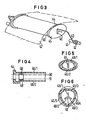
- Fig. 1 eine schematische Darstellung der erfindungsgemäBen Papiertransportvorrichtung in einer Fernschreibmaschine,
- Fig. 2 eine schematische Darstellung eines Schnittbildes der Papiertransportvorrichtung,
- Fig. 3 bis 6 Ausführungsformen der in der Papiertransportvorrichtung verwendeten Zugausgleichsvorrichtung,
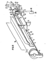
- Fig. 7 eine schematische Darstellung einer Papiertransportvorrichtung mit einer oberhalb der Schreibstelle angeordneten Papierandruckrolle und
- Fig. 8 eine schematische Darstellung des Schreibwalzenbereiches der Papiertransportvorrichtung mit einer über einen Federhebel geführten Papiertransportwelle, deren Andruckkraft an die Papierwalze veränderbar ist..
- 1 shows a schematic illustration of the paper transport device according to the invention in a teleprinter,
- 2 shows a schematic illustration of a sectional view of the paper transport device,
- 3 to 6 embodiments of the tension compensation device used in the paper transport device,
- Fig. 7 is a schematic representation of a paper transport device with a paper pressure roller arranged above the writing point and
- 8 shows a schematic representation of the platen area of the paper transport device with a paper transport shaft guided via a spring lever, the pressing force of which can be changed on the paper roll.
Die in der Figur 1 dargestellte Papiertransportvorrichtung für eine Fernschreibmaschine aus einer gestellfest gelagerten Vorratsrolle 1 aus Mehrlagenendlospapier, die über eine hier nicht dargestellte Vorrichtung in dem Gehäuse 2 der Fernschreibmaschine gelagert ist. Über eine später beschriebene Zugausgleicheinrichtung 3, die aus einem federn gelagerten Drahtbügel mit darauf schwimmend geführten Papierführungssattel besteht, wird das mehrlagige Endlospapier dem Papierführungskanal der Fernschreibmaschine zugeführt. Dieser Papierführungskanal enthält ein von der motorisch angetriebenen Schreibwalze 4 tangential wegfluchtendes Führungsblech 5 mit einer unterhalb der Schreibstelle einseitig gelagerten, mit nur einer Andruckrolle versehenen Papiertransportwelle 7 und einer sich an die Papiertransportwelle 7 anschließenden über die gesamte Breite der Papierwalze sich erstrekkenden federnden Papierandruckleiste 8. Im Schreibbetrieb wird ein Schreibkopf 9 mit einer hier nicht dargestellten Antriebseinrichtung zeilenweise entlang dem über die Schreibwalze 4 gespannten Aufzeichnungsträger bewegt. Der im folgenden näher beschriebene Papiertransport wird dabei durch die motorisch angetriebene Schreibwalze 4 in Verbindung mit der ebenfalls motorisch angetriebenen Papiertransportwelle durch Friction bewirkt. Das beschriebene Papier wird dabei von einer Ablage 6 im Deckel des Gehäuses 2 gestützt.The paper transport device shown in FIG. 1 for a teleprinter from a
Gemäß der Darstellung der Fig. 2 und 8 besteht der Kern der Papiertransportvorrichtung aus der über ein Getriebe 11 mit der Schreibwalze 4 motorisch angetriebenen Papiertransportwelle 7, die einseitig fest im Gestell 2 gelagert ist, und die mit ihrem anderen Ende von einem gestellfesten Federbügel 12 geführt wird. Auf der Papiertransportwelle 7 befindet sich eine Papierandruckrolle 13, die eine im Verhältnis zur Breite der Papierrolle schmalen zylindrischen Bereich 32 hat der in Berührung mit dem-Papier steht. Der zylindrische Bereich 32 läuft an beiden Seiten kegelig aus, wobei die kegeligen Seitenelemente auch tonnenförmige Gestalt haben können. Der Winkel α der Papierandruckleiste 8 zur Tangente an der Schreibwalze 4 und der Abstand A zwischen Papierandruckrolle 13 und der Papierandruckleiste 8 am Umfang der Schreibwalze 4 sind so gewählt, daß auch die Knicksteigigkeit leichter Papiere ausreicht, um die Andruckkraft F1 der Papierandruckleiste 8 ohne Stau zu überwinden. Um auch Mehrlagenpapier bis zu ungefähr 0,4 mm Dicke selbständig erfassen und einziehen zu können, ist der Durchmesser D der Papierandruckrolle 13-entsprechend groß dimensioniert. Die Papierandruckrolle 13 selbst ist unterhalb der durch die Papierandruckrolle 8 begrenzten Schreibstelle der Druckeinrichtung 90 angeordnet, so daß sich ein möglichst großer Umschlingungswinkel ß des mehrlagigen Endlospapieres 10 an der Schreibwalze 4 ergibt. Der hier dargestellte große Umschlingungswinkel.von ca 90° an der Schreibwalze 4 erlaubt eine weitgehende Streuung des Reibwertes des Schreibwalzenbelages. Durch die mittige Lage der tonnenförmigen Papierandruckrolle 13 in einer Ausnehmung 15 des Papierführungsbleches 5 ergibt sich in Verbindung mit einer seitlichen Papierführung 16 bzw. mit der Führung der.Zugausgleichseinrichtung 3 eine. "Lenkerwirkung", die den Transport des mehrlagigen Endlospapieres 10 sichert, ohne daß es dabei zu Verwerfungen der Lagen untereinander kommt. Um diese "Lenkerwirkung" zu erreichen, ist das Drehzahlverhältnis von Schreibwalze 4 zu Papierandruckrolle 13 so gewählt, daß ein kleiner Vortrieb von 0,5% bis 5% an der Andruckrolle 13 entsteht. Dieser Vortrieb, bedingt durch die unterschiedlichen Umfangsgeschwindigkeiten von Schreibwalze 4 und Papierandruckrolle 13, begrenzt die Schlaufenbildung an der Vorratsrolle 1 und verbessert die Umschlingung an der Schreibwalze 4 bei Mehrlagenpapier. Die Größe des Vortriebs ist abhängig von der Reibpaarung Andruckrolle-Papier und kann an unter Umständen auch größer als 5% sein. Die Andruckkraft F2 an der Papierandruckrolle 13 wird von einem gestellgestützten Federbügel 12 aus Draht über dessen Torsion erzeugt. Die Andruckkraft F2 kann sehr klein sein, da die Drehbewegung der Papierandruckrolle 13 mittels einer Zahnradstufe der Schreibwalze 4 erzeugt wird und damit reibungsunabhängig ist.2 and 8, the core of the paper transport device consists of the paper transport shaft 7, which is motor-driven via a gear 11 with the platen roller 4 and is fixedly mounted on one side in the
Im einzelnen besteht die Papiertransportvorrichtung entsprechend der Darstellung der Fig. 8 aus der Schreibwalze 4, die motorisch angetrieben drehbar im Gestell 2 gelagert ist. Unterhalb der Schreibwalze 4 befindet sich die über das Getriebe 11 mit Schreibwalze verbundene Papiertransportwelle 7 mit der darauf gelagerten und mit der Papiertransportwelle 7 fest verbundenen, tonnenförmigen Papierandruckrolle 13. Die Papiertransportwelle 7 mit der Papierandruckrolle 13 befindet sich am Ende des durch das Papierführungsblech 5 begrenzten Papierführungsbereiches und ist einseitig im Gestell 2 und mit ihrem anderen Ende entsprechend der Pfeilrichtung drehbar in einer Öse 17 eines Armes des gestellgestützten Federbügels 12 gelagert. Abhängig von dem verwendeten Aufzeichnungsträger (Endlospapier, Mehrlagenpapier, Einzelblatt) kann über den Federbügel 12 die Papierandruckrolle 13.mehr oder weniger stark an die Papierwalze 4 bzw. das dazwischenliegende Papier 10gedrückt werden. Zum Einlegen und Justieren ist außerdem ein totales Abschwenken der Papierandruckrolle 13 möglich. Zu diesem Zwecke befindet sich der gestellfest in Führung'18 gelagerte Federbügel mit seinem anderen Arm in Wirkverbindung mit einem Schwenkhebel 19, der wiederum um eine Achse 20 drehbar gelagert ist.In detail, the paper transport device, as shown in FIG. 8, consists of the platen roller 4, which is rotatably mounted in the
Der.Schwenkhebel besteht aus einem Griffstück 21 mit einem unterhalb des Griffstückes angeordneten Ansatzstück 22. Im dargestellten angedrückten Zustand der Papierandruckrolle 13 liegt unter der Torsionswirkung des Federbügels 12 der Federbügel mit einem Ende an diesem Ansatzstück 22 an. Durch Verschwenken des Schwenkhebels 19 entsprechend der dargestellten Pfeilrichtung kann dabei die Papierrolle der Schreibwalze 4 weggeschwenkt werden.The swivel lever consists of a grip piece 21 with an
Zum Erkennen des Vorhandenseins von Papier in der Papierführung ist ein Abtästfederbügel 23 vorgesehen. Der Abtastfederbügel 23 greift mit seinem schlaufenförmig umgebogenen Abtastende 24 drch eine Öffnung des Papierführungsbleches 5 und stützt sich auf der Schreibwalze 4 ab. Der Abtastfederbügel 23 ist mehrfach umgebogen und mit seinem äußeren Ende in einer Ausnehmung 25 des Papierführungsbleches 5 ortsfest gelagert. Der Abtastfederbügel 23 wird dabei durch ein exzentrisch gegenüber der Drehachse des Teiles 20 angeordnetes Führungsstück 26 des Schwenkhebels 19 geführt, wobei das dem Äbtastende entgegengesetzt gelegene Teil des AbtastfederbUgels 23 einen U-förmigen Verlauf hat und an einer als Schalter ausgebildeten elektrischen Abtasteinrichtung 27 anliegt. Das Zusammenwirken des Abtastfederbügels 23 mit der elektrischen Abtasteinrichtung 27 und dem Federbügel 12 ist wie folgt:A scanning
Befindet sich in der Papierführung ein Papier, so .wird das Abtastende 24 und damit der Abtastfederbügel 23 von der Schreibwalze 4 abgehoben. Der Schwenkhebel 19 befindet sich dabei in der dargestellten Grundposition mit angedrückter Papierandruckrolle 13. Die elektrische Abtasteinrichtung 27 liegt mit ihrer Taste 28 an dem Mit-. telstück des Abtastbügels an. Im dargestellten Zustand mit eingelegtem Papier ist also die elektrische Abtasteinrichtung betätigt und damit ein in der elektrischen Abtasteinrichtung enthaltender Schalter geöffnet. Der geöffnete Schalter unterbricht einen aus einer Stromquelle 29 und einer Warnlampe 30 bestehenden Stromkreis, so daß die Warnlampe 30 gelöscht ist. Selbstverständlich kann die elektrische Abtasteinrichtung 27 auch an einen zentralen Mikroprozessor der Druckeinrichtung angeschlossen sein der die Betriebszustände (Ein-Aus) in Abhängigkeit von der Abtasteinrichtung steuert.If there is paper in the paper guide, the scanning
Nach Durchlauf des Papieres 10 durch die Papierführung legt sich der Abtastfederbügel infolge seines Federverhaltens entsprechend der dargestellten Pfeilrichtung an die Schreibwalze S an. Dadurch wird der Taster 28 ebenfalls in Pfeilrichtung bewegt und der Warnstromkreis geschlossen. Die Warnlampe 30 leuchtet auf.After the
Dieses Aufleuchten der Warnlampe erfolgt auch, wenn der Schwenkhebel 19 zum Verschwenken der Papiertransportwelle in Pfeilrichtung bewegt wird. Durch diese Bewegung wird über das exzentrische Führungsstück 2,6 der Abtastfederbügel 23 um den Winkel 31 verschwenkt, was wiederum ein Schließen des Warnstromkreises und damit ein Aufleuchten der Warnlampe 30 zur Folge hat. Damit ist es möglich, die elektrische Abtasteinrichtung 27 sowohl zum Abtasten der Papiereinzugsvorrichtung auf Papierende als auch zum Abtasten des Verschwenkungszustandes der Papierandruckrolle zu verwenden.This warning lamp also lights up when the
Die zur Erzeugung einer Vorspannung des mehrlagigen Endlospapieres 10 zwischen der Vorratsrolle 1 und der Schreibwalze 4 vorgesehene Zugausgleicheinrichtung 3(Fig.3) besteht aus einem auf einer Achse 41 durch Umschlingungen 42 federn gelagerten Federbügel 43, auf dem ein seitliche Führungselemente 44 aufweisender Papierführungsbügel 45 mit breiter Papierauflagefläche 46 schwimmend, d.h. seitlich verschiebbar, gelagert ist. Die Papierauflagefläche 47 führt und zentriert das mehrlagige Endlospapier 47. Um den Papierführungssattel an mehrlagiges Endlospapier verschiedener Breite leicht anpassen zu können, sind die seitlichen Führungen 44 mit den Papierauflageflächen 46/1 und 46/2 über Rastelemente auswechselbar verbunden. Dabei ist der Papierführungssattel entsprechend dem Schnittbild der Figur 5 rohrförmig ausgebildet und weist mehrere Papierauflageflächen 46/1 und 46/2 auf. Die entsprechende Anpassung des mit zwei Papierauflageflächen 46/1 und 46/2 versehenen Papierführungssattels an die entsprechende Breite des mehrlagigen Endlospapiers erfolgt durch einfaches Verschwenken des Papierführungssattels 45 auf dem Drahtbügel 43. Dabei gleitet der Drahtbügel 43 in einer Langlochführung 49, und die Achsenlänge verändert sich entsprechend der Darstellung der Fig. 4 von der Position 50 zur Position 51 und umgekehrt. Das bedeutet, die Einstellung erfolgt durch einfaches Schwenken des Papierführungssattels 45 um 180°. Das auf dem Papierführungssattel 45 aufliegende Papier 47 sorgt dabei durch sein Eigengewicht bzw. durch die Andruckkraft der Feder 42 dafür, daß sich der Papierführungssattel des Betriebes nicht verschwenken kann.The tension compensation device 3 (FIG. 3) provided for generating a pretension of the multi-layer
Gestaltet man entsprechend der Darstellung der Fig. 6 die zentrale Führung 49 für den Drahtbügel 43 sternförmig aus, so lassen sich auf dem Umfang des Papierführungssattels 44 drei Papierauflageflächen 46/3, 46/4 und 46/5 unterschiedlicher Breite anordnen. Beim Wechsel zwischen den einzelnen Papierauflageflächen wird der Drahtbügel in die Position 49/1 oder 49/2 oder 49/3 gebracht.If the
Eine besonders vorteilhafte und einfache Ausgestaltung der Papiereinzugsvorrichtung ergibt sich, wenn man entsprechend der Darstellung der Fig. 7 die motorisch angetriebene Papierandruckrolle 13 oberhalb der Schreibstelle, d.h. in Vorschubrichtung hinter der Schreibstelle anordnet. Dadurch ergibt sich eine besonders einfache Umschlingung bei gleichmäßiger Anlage des Papieres 10 an.der Schreibwalze. Durch die große Umschlingung kann die Andruckkraft der Andruckrolle 13 noch weiter besenkt werden, so daß auch dünnste Papiere mit entsprechenden Kohlezwischenlagen ohne Druckstellenspuren durch die Papiertransportvorrichtung transportiert werden können. Die Zugausgleichseinrichtung 3 (Fig. 7) in Verbindung mit einem trichterförmig ausgebildeten Papierzuführungskanal aus dem seitlichen Führungsblech 5 mit einem Gegenblech 5/1, das z.B. aus einer Gehäusewand bestehen kann, führt zu einer besonders schonenden Behandlung des Mehrlagenpapieres. Die von der Papierrolle 1 voreingeprägte Krümmung des mehrlagigen Aufzeichnungsträgers wird beim Durchlauf durch die Papiereinzugsvorrichtung und damit durch die gesamte Druckeinrichtung beibehalten. Durch diese einheitliche Führung des Mehrlagenendlospapieres durch die gesamte Druckeinrichtung ergibt sich eine besonders gute Justierung der einzelnen Lagen des Mehrlagenendlospapieres zueinander und damit ein völlig gleichmäßiger Zeilenstand. Die gesamte Druckeinrichtung läßt sich besonders kompakt aufbauen. Zum Abreißen des Endlospapieres kann oberhalb der Papierandruckrolle 13 eine Abreißkante 32 angeordnet sein, die durch ihre Nähe zur Papierandruckrolle 13 ein besonders leichtes und exaktes Abreißen des bedruckten Endlospapieres ermöglicht.A particularly advantageous and simple embodiment of the paper feed device is obtained if, as shown in FIG. 7, the motor-driven
Claims (12)
Applications Claiming Priority (2)
| Application Number | Priority Date | Filing Date | Title |
|---|---|---|---|
| DE3240914 | 1982-11-05 | ||
| DE3240914 | 1982-11-05 |
Publications (3)
| Publication Number | Publication Date |
|---|---|
| EP0108388A2 true EP0108388A2 (en) | 1984-05-16 |
| EP0108388A3 EP0108388A3 (en) | 1985-07-17 |
| EP0108388B1 EP0108388B1 (en) | 1987-09-09 |
Family
ID=6177392
Family Applications (1)
| Application Number | Title | Priority Date | Filing Date |
|---|---|---|---|
| EP83110925A Expired EP0108388B1 (en) | 1982-11-05 | 1983-11-02 | Paper transporting device for endless paper printing installations with a single paper pressing roll |
Country Status (5)
| Country | Link |
|---|---|
| US (1) | US4561792A (en) |
| EP (1) | EP0108388B1 (en) |
| CA (1) | CA1225350A (en) |
| DE (1) | DE3373440D1 (en) |
| ZA (1) | ZA838230B (en) |
Cited By (3)
| Publication number | Priority date | Publication date | Assignee | Title |
|---|---|---|---|---|
| DE3436684A1 (en) * | 1984-10-05 | 1986-04-10 | Siemens AG, 1000 Berlin und 8000 München | Paper guiding element for printing devices for continuous paper |
| US4592670A (en) * | 1984-06-29 | 1986-06-03 | International Business Machines Corporation | Angular motion paper feed release system |
| US4773782A (en) * | 1985-10-28 | 1988-09-27 | Canon Kabushiki Kaisha | Apparatus for transferring sheet material |
Families Citing this family (5)
| Publication number | Priority date | Publication date | Assignee | Title |
|---|---|---|---|---|
| JPS62208970A (en) * | 1986-03-10 | 1987-09-14 | Minolta Camera Co Ltd | Printer |
| IT1230273B (en) * | 1989-06-14 | 1991-10-18 | Bull Hn Information Syst | AUTOMATIC ACTUATOR OF PAPER PREMICARD DEVICE FOR PRINTER. |
| DE59300291D1 (en) * | 1993-07-28 | 1995-07-27 | Siemens Nixdorf Inf Syst | Heat-fixing device for recording media of a printing or copying machine printed on one or both sides. |
| SG87014A1 (en) * | 1998-12-28 | 2002-03-19 | Hewlett Packard Co | Apparatus for feeding media in a printer |
| US6364554B2 (en) * | 1999-12-29 | 2002-04-02 | Hewlett-Packard Company | Apparatus for feeding media in a printer |
Citations (6)
| Publication number | Priority date | Publication date | Assignee | Title |
|---|---|---|---|---|
| DE1954261A1 (en) * | 1968-10-28 | 1970-05-27 | Burroughs Corp | Swiveling roller pressure device |
| US3908810A (en) * | 1974-06-19 | 1975-09-30 | Teletype Corp | Printer paper roll holder with spring-controlled line feed tensioner |
| DE2847577A1 (en) * | 1978-11-02 | 1980-05-08 | Olympia Werke Ag | Ink printing or copying machine - has two pressure rollers acting at edges of paper to keep paper taut |
| DE2503642B2 (en) * | 1975-01-29 | 1980-07-10 | Standard Elektrik Lorenz Ag, 7000 Stuttgart | Paper guide for automatically operated office machines |
| DE3014340A1 (en) * | 1980-04-15 | 1981-10-22 | Adlerwerke Vorm. Heinrich Kleyer Ag, 6000 Frankfurt | DEVICE FOR PRESSING AND LIFTING A PAPER TRANSPORT SHAFT FROM A TYPE ROLLER OF A TYPEWRITER, A PRINTER OR THE LIKE. |
| US4341480A (en) * | 1979-12-26 | 1982-07-27 | General Electric Company | Feed mechanism for continuous and cut form paper |
Family Cites Families (18)
| Publication number | Priority date | Publication date | Assignee | Title |
|---|---|---|---|---|
| DE253360C (en) * | ||||
| US991706A (en) * | 1909-12-08 | 1911-05-09 | Underwood Typewriter Co | Type-writing machine. |
| US1100442A (en) * | 1912-04-29 | 1914-06-16 | Remington Typewriter Co | Type-writing machine. |
| US1213189A (en) * | 1915-03-30 | 1917-01-23 | Underwood Computing Machine Co | Type-writing machine. |
| US1221236A (en) * | 1915-11-24 | 1917-04-03 | Remington Typewriter Co | Type-writing machine. |
| US1363294A (en) * | 1919-12-20 | 1920-12-28 | Underwood Typewriter Co | Typewriting-machine |
| US1539244A (en) * | 1923-03-03 | 1925-05-26 | Underwood Typewriter Co | Typewriting machine |
| US2142603A (en) * | 1938-01-31 | 1939-01-03 | Madge D Brown | Sheet signal for typewriters |
| DE851069C (en) * | 1938-11-19 | 1952-10-02 | Ncr Co | Document conveyor device for typing, calculating or accounting machines |
| US2353407A (en) * | 1941-06-26 | 1944-07-11 | Underwood Elliott Fisher Co | Typewriting machine |
| FR1407100A (en) * | 1964-05-15 | 1965-07-30 | Bull Sa Machines | Improvements in placing and advancing paper in printing machines |
| US3586149A (en) * | 1969-02-07 | 1971-06-22 | Data Products Co | Web tensioning apparatus |
| US3572601A (en) * | 1969-04-14 | 1971-03-30 | Data Products Corp | Web feed system suitable for use in high-speed printers |
| US3519117A (en) * | 1969-05-23 | 1970-07-07 | Singer Co | Feed roller construction and drive |
| US4114750A (en) * | 1975-08-06 | 1978-09-19 | Hydra Corporation | Printer system having local control for dynamically alterable printing |
| US4019619A (en) * | 1976-03-22 | 1977-04-26 | Printronix, Inc. | Paper feed sensing mechanism for printer |
| DE2713333C3 (en) * | 1977-03-25 | 1981-12-10 | Siemens AG, 1000 Berlin und 8000 München | Device for guiding the paper during paper transport in printing devices, in particular in telex machines |
| DE2943241C2 (en) * | 1979-10-23 | 1982-05-13 | Mannesmann AG, 4000 Düsseldorf | Paper end switching device for a printer |
-
1983
- 1983-11-02 EP EP83110925A patent/EP0108388B1/en not_active Expired
- 1983-11-02 DE DE8383110925T patent/DE3373440D1/en not_active Expired
- 1983-11-03 US US06/548,543 patent/US4561792A/en not_active Expired - Fee Related
- 1983-11-03 CA CA000440412A patent/CA1225350A/en not_active Expired
- 1983-11-04 ZA ZA838230A patent/ZA838230B/en unknown
Patent Citations (7)
| Publication number | Priority date | Publication date | Assignee | Title |
|---|---|---|---|---|
| DE1954261A1 (en) * | 1968-10-28 | 1970-05-27 | Burroughs Corp | Swiveling roller pressure device |
| US3908810A (en) * | 1974-06-19 | 1975-09-30 | Teletype Corp | Printer paper roll holder with spring-controlled line feed tensioner |
| DE2503642B2 (en) * | 1975-01-29 | 1980-07-10 | Standard Elektrik Lorenz Ag, 7000 Stuttgart | Paper guide for automatically operated office machines |
| DE2847577A1 (en) * | 1978-11-02 | 1980-05-08 | Olympia Werke Ag | Ink printing or copying machine - has two pressure rollers acting at edges of paper to keep paper taut |
| US4341480A (en) * | 1979-12-26 | 1982-07-27 | General Electric Company | Feed mechanism for continuous and cut form paper |
| DE3014340A1 (en) * | 1980-04-15 | 1981-10-22 | Adlerwerke Vorm. Heinrich Kleyer Ag, 6000 Frankfurt | DEVICE FOR PRESSING AND LIFTING A PAPER TRANSPORT SHAFT FROM A TYPE ROLLER OF A TYPEWRITER, A PRINTER OR THE LIKE. |
| US4342521A (en) * | 1980-04-15 | 1982-08-03 | Adlerwerke Vorm Heinrich Kleyer A.G. | Paper feeding apparatus |
Cited By (3)
| Publication number | Priority date | Publication date | Assignee | Title |
|---|---|---|---|---|
| US4592670A (en) * | 1984-06-29 | 1986-06-03 | International Business Machines Corporation | Angular motion paper feed release system |
| DE3436684A1 (en) * | 1984-10-05 | 1986-04-10 | Siemens AG, 1000 Berlin und 8000 München | Paper guiding element for printing devices for continuous paper |
| US4773782A (en) * | 1985-10-28 | 1988-09-27 | Canon Kabushiki Kaisha | Apparatus for transferring sheet material |
Also Published As
| Publication number | Publication date |
|---|---|
| US4561792A (en) | 1985-12-31 |
| EP0108388A3 (en) | 1985-07-17 |
| CA1225350A (en) | 1987-08-11 |
| DE3373440D1 (en) | 1987-10-15 |
| ZA838230B (en) | 1984-06-27 |
| EP0108388B1 (en) | 1987-09-09 |
Similar Documents
| Publication | Publication Date | Title |
|---|---|---|
| DE2655832C2 (en) | Separating device for separating paper webs in a printer | |
| DE4335473C2 (en) | Turning device for a tape-shaped recording medium | |
| EP0969969B1 (en) | Printer for printing on single sheets and an endless paper strip | |
| EP0099958B1 (en) | Apparatus for feeding record carriers to printers, in particular matrix printers | |
| DE2829827C2 (en) | Guide device for recording media in printing works | |
| EP3838604B1 (en) | Label printer | |
| EP0108388B1 (en) | Paper transporting device for endless paper printing installations with a single paper pressing roll | |
| DE2717315A1 (en) | RECORDING MEDIUM TRANSPORT DEVICE FOR A PERFORATED EDGE RECORDING CARRIER | |
| DE3139117C1 (en) | Variable folder with a pair of cutting cylinders and a pair of tear-off rollers arranged below this | |
| DD289506A5 (en) | DEVICE FOR DELIVERING RAILWAY GOOD TO A MACHINING STATION | |
| DE3214549C2 (en) | Transport device for folding paper with punched edges and for roll paper | |
| DE3723391A1 (en) | PRINTER | |
| EP0123310B1 (en) | Sheet and web feeding device for printers | |
| DE60103566T2 (en) | Pressure abutment and pressure device | |
| DE3636814C2 (en) | ||
| EP0111702B1 (en) | Paper introduction devices with slewable paper transport shaft | |
| EP0127868B1 (en) | Paper draw-in device for typewriters or office machines with a paper-compensating gap disposed in the paper-guiding channel | |
| DE1262645B (en) | Raster printer | |
| DE2212957B2 (en) | Device for forming a copy material loop within an automatic conveying device for copy material in a copying machine | |
| DE2503642C3 (en) | Paper guide for automatically operated office machines | |
| EP0099957B1 (en) | Apparatus for feeding record carriers to printers, in particular matrix printers | |
| DE4235704C1 (en) | Longitudinal buffer for electrophotographic printer or copier - provided in path of recording carrier in endless format and forms loop for compensation of varying transport speeds of differing sets of printer or copier | |
| EP0108389B1 (en) | Paper introduction device for a line printing installation with an equipment for paper end tracing | |
| EP0101071B1 (en) | Paper feeding device for printing installations | |
| DE3230190C2 (en) | Paper feeding device for printer equipment |
Legal Events
| Date | Code | Title | Description |
|---|---|---|---|
| PUAI | Public reference made under article 153(3) epc to a published international application that has entered the european phase |
Free format text: ORIGINAL CODE: 0009012 |
|
| AK | Designated contracting states |
Designated state(s): BE CH DE FR GB IT LI NL SE |
|
| 17P | Request for examination filed |
Effective date: 19841213 |
|
| PUAL | Search report despatched |
Free format text: ORIGINAL CODE: 0009013 |
|
| AK | Designated contracting states |
Designated state(s): BE CH DE FR GB IT LI NL SE |
|
| 17Q | First examination report despatched |
Effective date: 19861118 |
|
| GRAA | (expected) grant |
Free format text: ORIGINAL CODE: 0009210 |
|
| AK | Designated contracting states |
Kind code of ref document: B1 Designated state(s): BE CH DE FR GB IT LI NL SE |
|
| REF | Corresponds to: |
Ref document number: 3373440 Country of ref document: DE Date of ref document: 19871015 |
|
| ET | Fr: translation filed | ||
| ITF | It: translation for a ep patent filed |
Owner name: STUDIO JAUMANN |
|
| GBT | Gb: translation of ep patent filed (gb section 77(6)(a)/1977) | ||
| PLBE | No opposition filed within time limit |
Free format text: ORIGINAL CODE: 0009261 |
|
| STAA | Information on the status of an ep patent application or granted ep patent |
Free format text: STATUS: NO OPPOSITION FILED WITHIN TIME LIMIT |
|
| 26N | No opposition filed | ||
| PGFP | Annual fee paid to national office [announced via postgrant information from national office to epo] |
Ref country code: BE Payment date: 19891117 Year of fee payment: 7 |
|
| PGFP | Annual fee paid to national office [announced via postgrant information from national office to epo] |
Ref country code: NL Payment date: 19891130 Year of fee payment: 7 |
|
| PGFP | Annual fee paid to national office [announced via postgrant information from national office to epo] |
Ref country code: CH Payment date: 19900222 Year of fee payment: 7 |
|
| PGFP | Annual fee paid to national office [announced via postgrant information from national office to epo] |
Ref country code: GB Payment date: 19901018 Year of fee payment: 8 |
|
| PGFP | Annual fee paid to national office [announced via postgrant information from national office to epo] |
Ref country code: SE Payment date: 19901121 Year of fee payment: 8 |
|
| ITTA | It: last paid annual fee | ||
| PG25 | Lapsed in a contracting state [announced via postgrant information from national office to epo] |
Ref country code: LI Effective date: 19901130 Ref country code: CH Effective date: 19901130 Ref country code: BE Effective date: 19901130 |
|
| BERE | Be: lapsed |
Owner name: SIEMENS A.G. BERLIN UND MUNCHEN Effective date: 19901130 |
|
| PG25 | Lapsed in a contracting state [announced via postgrant information from national office to epo] |
Ref country code: NL Effective date: 19910601 |
|
| NLV4 | Nl: lapsed or anulled due to non-payment of the annual fee | ||
| REG | Reference to a national code |
Ref country code: CH Ref legal event code: PL |
|
| PG25 | Lapsed in a contracting state [announced via postgrant information from national office to epo] |
Ref country code: GB Effective date: 19911102 |
|
| PG25 | Lapsed in a contracting state [announced via postgrant information from national office to epo] |
Ref country code: SE Effective date: 19911103 |
|
| GBPC | Gb: european patent ceased through non-payment of renewal fee | ||
| PGFP | Annual fee paid to national office [announced via postgrant information from national office to epo] |
Ref country code: FR Payment date: 19921123 Year of fee payment: 10 |
|
| PGFP | Annual fee paid to national office [announced via postgrant information from national office to epo] |
Ref country code: DE Payment date: 19930122 Year of fee payment: 10 |
|
| PG25 | Lapsed in a contracting state [announced via postgrant information from national office to epo] |
Ref country code: FR Effective date: 19940729 |
|
| PG25 | Lapsed in a contracting state [announced via postgrant information from national office to epo] |
Ref country code: DE Effective date: 19940802 |
|
| REG | Reference to a national code |
Ref country code: FR Ref legal event code: ST |
|
| EUG | Se: european patent has lapsed |
Ref document number: 83110925.1 Effective date: 19920604 |