EP0109037A1 - Process and device for evaluating the noise level on a telephone line - Google Patents
Process and device for evaluating the noise level on a telephone line Download PDFInfo
- Publication number
- EP0109037A1 EP0109037A1 EP83111149A EP83111149A EP0109037A1 EP 0109037 A1 EP0109037 A1 EP 0109037A1 EP 83111149 A EP83111149 A EP 83111149A EP 83111149 A EP83111149 A EP 83111149A EP 0109037 A1 EP0109037 A1 EP 0109037A1
- Authority
- EP
- European Patent Office
- Prior art keywords
- value
- circuit
- level
- signal
- values
- Prior art date
- Legal status (The legal status is an assumption and is not a legal conclusion. Google has not performed a legal analysis and makes no representation as to the accuracy of the status listed.)
- Granted
Links
Images


Classifications
-
- H—ELECTRICITY
- H04—ELECTRIC COMMUNICATION TECHNIQUE
- H04J—MULTIPLEX COMMUNICATION
- H04J3/00—Time-division multiplex systems
- H04J3/17—Time-division multiplex systems in which the transmission channel allotted to a first user may be taken away and re-allotted to a second user if the first user becomes inactive, e.g. TASI
- H04J3/175—Speech activity or inactivity detectors
-
- G—PHYSICS
- G01—MEASURING; TESTING
- G01R—MEASURING ELECTRIC VARIABLES; MEASURING MAGNETIC VARIABLES
- G01R29/00—Arrangements for measuring or indicating electric quantities not covered by groups G01R19/00 - G01R27/00
- G01R29/26—Measuring noise figure; Measuring signal-to-noise ratio
Definitions
- the present invention relates to telephone transmission and relates to the evaluation of the noise level on a telephone channel. It more particularly aims to solve the problem of such an evaluation on the basis of the signals present on the channel in service, that is to say on the basis of signals consisting of speech (or signaling) signals to which the noise is superimposed. , separated by intervals of silence occupied only by noise.
- the devices for concentrating telephone signals by speech interpolation which equip certain multi-channel telephone links, increase the capacities of these links by avoiding the transmission of silence in conversations. They therefore include speech detectors to identify speech periods and periods of silence on each of the channels to be concentrated.
- the performance of these concentration devices is directly dependent on the quality of the speech / silence discrimination carried out by these speech detectors.
- these speech detectors have a high insensitivity to noise in order to allow a high concentration rate, while being very sensitive to speech signals in order to avoid hashing of speech.
- any signal on the monitored channel whose level over a time interval is greater than a threshold placed above the noise level on the channel is presumed to be a speech signal and the rest of the silence.
- the maximum noise level admitted by the CCITT for a telephone channel ie -40 dBmo.
- the noise level on a telephone channel can differ significantly from this value and better speech / silence discrimination can be obtained by evaluating the noise level on the monitored channel and varying the comparison threshold according to the evaluated noise level. , as has already been proposed.
- Evaluating the noise level on a telephone channel is also useful for generating pleasant noise in certain telephone networks.
- the path that defines the four son circuitry for transmission in the direction of the receiving subscriber who is silent towards the speaking subscriber is cut off in order to block the propagation of echo signals. It is known to then inject on this channel, downstream of the cutoff, an approval noise intended to compensate for the contribution to the background noise normally perceived by the receiving subscriber for this direction of transmission, of the network equipment from which this subscriber is disconnected due to this interruption.
- These two filters process the signal present on the channel being processed during the periods of silence identified by the speech detector; the first also processes the signal present on this channel during the periods of activity identified by the speech detector while the second is then constantly initialized at twice the value of the output signal of the first.
- the noise level on the channel is evaluated at the last common value of convergence of these two filters.
- Such a procedure is based on the fact that the background noise on a telephone channel is generally fairly stationary in contrast to the speech signals which have a non-stationary character.
- the two filters whose equivalent time constants are close to 8 ms and 0.128 ms respectively, do not converge to the same value until a background noise has been present on the channel alone for a relatively long period; this common value of convergence then translates the average noise level.
- an averaging circuit develops a representation of the average level of the signal present on the channel in processing over an elementary time interval.
- Two sampling and recording circuits extract and keep one the maximum value the other the minimum value of this representation, these two circuits being reset at the same variable rate of long period relative to the elementary interval.
- a comparator compares the maximum and minimum values provided by the two sampling and recording circuits with each other, in order to identify the moments when these two values satisfy a given relationship reflecting a small relative difference between them. The noise level is then obtained from the minimum values of the representation for which this relation is satisfied.
- the equivalent time constant of the averaging circuit is 16 ms and the reinitialization of the two sampling and recording circuits is carried out at a faster rate when the channel is presumed to be inactive than when it these are presumed to be active, every 256 ms and every 2 s respectively, these presumed channel states corresponding to states of a sequential machine whose evolution takes place under the command of parameters depending on the level representation means of the signal present on the channel, in the determination of which the evaluated noise level intervenes.
- the noise level is only evaluated during fairly long intervals of silence. This can lead to very long acquisition times, especially in the case where not only speech signals from a subscriber transmitting on this channel are propagated on the channel, but also echo signals from the correspondent's speech signals. of this subscriber, the assessment of the noise level then being made only when the two subscribers are silent for an appreciable duration.
- these two solutions involve tracking speech and silence periods using complex arrangements, heavy in the context of an application other than speech detection.
- the object of the present invention is to remedy these drawbacks by allowing rapid and precise evaluation of the noise level on a telephone route by means of a simple arrangement.
- each selected value is weighted more or less strongly depending on whether or not it is equal to the current value of the evaluated noise level.
- the noise level evaluation device illustrated in the drawings is of the digital type. It is intended to process an available telephone channel signal in the form of successive digital samples. For the simplicity of the presentation, it deals with only one way. Of course, it could be adapted to the time-sharing processing of a plurality of channels.
- the device according to the invention illustrated in FIG. 1 has an input 1 to which the bits defining the amplitude of the digital samples of the signal present on a telephone channel to be processed are applied in parallel, regardless of the polarity of these samples, an input 2 on which a clock signal H is applied to the sampling rate and an output 3 on which the value of the evaluated noise level is available, ie NB, also defined in digital form.
- circuit 4 for evaluation and selection values of the level of the signal present on the channel, connected to its two inputs 1 and 2, a circuit 5 for analysis of the selected values delivered by the circuit 4, arranged following this circuit 4 and further connected to the input 2 to receive the clock signal H, supplying the value of the noise level evaluated NB on the output 3, and a timing circuit 6 elaborating from the clock signal H which it receives from the input 2 different timing signals specified below, which are necessary for the proper functioning of circuits 4 and 5.
- Circuit 4 evaluates the level of the signal present on the telephone channel over successive time intervals I of the same duration, long with respect to the period of the clock signal H at the sampling rate, and selects those of the level values. of this signal falling in a given range P considered as the range of possible noise level values and called noise level range. It provides, on a first output, a logic signal L indicating for each level value of this signal whether or not it falls within the range P and, on a second output, each of the level values of this signal falling in the range range P, these values falling in the range P and designated by N being expressed using a limited set of r different values designated N to N ...
- circuit 4 consists of a circuit d level evaluation 40 which receives the bits of the samples applied to the input 1, that is to say samples of the signal present on the telephone channel, and of a selection circuit 41 which receives the level values produced by the circuit 40 and selects those of the values which fall in the range P.
- the circuit 40 evaluating the level of the signal present on the channel, with regard to the range P, using here a set of values in greater number at r, the selection circuit 41 also ensures here a transcoding of the values which it s elects, allowing them to be expressed using the r values M 0 to Nr-l *
- the circuit 4 receives from the timing circuit 6 a timing signal C 1 defining the intervals T_ and a sequence signal 3 1 defining identical sequences s 1 each taking place over an entire interval I and defining therein different operating phases of the circuit 4 which will be specified below during the detailed description of this circuit given with reference to FIG. 2.
- time intervals I over which the evaluation of the level of the signal present on the telephone channel is carried out are of duration chosen to be long with respect to the period of the lower limit frequency of the bandwidth, ie long with respect to 3 p 0 s 3.3 ms, and short compared to the average time to establish or drop the syllables which is of the order of forty milliseconds.
- the circuit 5 for analyzing the selected values N which it receives from the circuit 4 is sensitive to their distribution between the different values N to N r-1
- the majority of these selected values N is in fact generally concentrated on one of the values No to N r-1 and it is this latter value which is identified by circuit 5 and considered as significant of the noise level on the channel.
- the evaluation made by circuit 4 of the level of this signal provides level values which fall in the range P and are therefore selected and which prove to be very little dispersed (due to the quasi "stationary" nature of the noise), generally concentrated mainly on one of the values No to N r-1 and secondarily on the two adjacent values or where appropriate l 'unique value adjacent to it.
- the signal level values on the telephone channel which either fall outside the range of level P and are therefore ignored by circuit 5 or fall in the range P but prove to be very dispersed (due to the "non-stationary" nature of the speech signals), fail to overturn a previously established majority.
- the telephone channel also carries signaling signals at certain times; these are very high level signals and are not likely to have a significant effect on the distribution calculations made by circuit 5.
- This circuit 5 performs a relative accounting of the selected values N which are expressed by the different values N o to N rl * It counts the selected values N expressed by each of these different values N to N r-1 and makes them evolve relatively by compared to the others the r resulting accounts for each new selected value N which it receives from circuit 4.
- circuit 5 takes into account the position of the account concerned by the new selected value N received in relation to a high threshold set for all accounts and, if applicable, also takes into account the positions of all other accounts in relation to a low threshold fixed for all accounts: if the account concerned by this new selected value does not exceed this high threshold, it increases this concerned account by a certain quantity while the other accounts remain unchanged, if on the other hand the account concerned by this new value already exceeds this high threshold, this account concerned remains unchanged while those of other accounts above the low threshold given for all accounts are reduced by a certain amount.
- the circuit 5 selects according to a given mode one of the signal level values concerned by these accounts in question; it is here the largest of these values concerned which is retained to be delivered at the output of this circuit.
- the circuit 5 receives from the timing circuit 6 a sequence signal 3 2 determining within each interval I a plurality of identical sequences s 2 each of r periods of the clock signal H, with a view to execution in series , in each interval I, of operations concerning the r values N to N r- 1. It also receives from this same timing circuit 6, two signals V 1 and V 2 having periods of the same duration as that of the intervals I, both of the same shape and identifying in each interval I respectively two of the sequences s 2 during which the circuit 5 performs all the processing operations to be executed in this interval. It also receives, from the timing circuit, a signal C 2 at the same form as the signal C 1 but delayed relative to the latter to take account of the processing times.
- r is chosen equal to 16 and that the 16 values N to N 1 5 extend regularly spaced in dB over the noise level range going substantially from -55dBmo to -35dBmo.
- the duration of the time intervals I is chosen to be equal to 16 ms.
- circuit 4 is detailed, consisting of the level evaluation circuit 40 and the selection circuit 41.
- the level evaluation circuit 40 consists of a control loop comprising a comparator 400, a circuit 401 for defining the variation of the value n of a comparison level to be applied to the comparator 400 and an accumulator 402 accumulating variation steps p defined by circuit 401.
- the comparator 400 receives, on a first input forming the input of the circuit 40 connected to the input 1 of the device, the 7-bit value (of weight 2 0 to 2 6 ) of the amplitude of the successive samples of the signal present on the telephone channel. It receives on a second input the value of the variable level of comparison n which will be delivered on the output of the circuit 40. In response to these two input signals, it delivers a logic signal indicating by its level "1" or "0" whether or not the value of the current sample of the signal present on the telephone channel is greater than the value of the comparison level n.
- the circuit 401 for defining the variation of the value of the comparison level n is connected to the output of the comparator 400. It receives, in addition to the logic signal delivered by the comparator, the sequence signal s 1 to define the step of variation p of the comparison value n, which will be positive or negative depending on whether the logic output signal of the comparator is at level "1" or "0", the absolute value of which is determined by the signal S and goes over each interval I, decreasing as the sequence s 1 takes place.
- the circuit 401 which can be constituted by a PROM type memory, defines the variation steps p on 9 bits, one of which for the sign, of value 1 for the sign + and of value 0 for the sign -, and eight for the absolute value, of respective weights 2 3 to 2 by expressing the absolute value of the negative steps by its complement to 2 5 , which allows, as is well known to replace subtractions by additions in the calculations to be performed.
- the accumulator 402 is connected to the output of the circuit 401 and also receives the clock signal H. It accumulates at the sampling rate, between a lower stop and an upper stop, the variation steps p defined by the circuit 401 to deliver the value of level n supplied at the output of the level 4o evaluation circuit and applied to the second input of the comparator.
- This accumulator 402 is limited to eight weight bits respective 2- 3 to 2 4.
- the content of the accumulator therefore changes from 0 to 31 +? , which represents a level range which includes the noise level range P by extending beyond it above as well as below.
- the accumulator 402 can be produced, as shown, using an adder 403 with two eight-bit inputs, a multiplexer 404 with two also 8-bit multiplexing inputs, a register 405 with eight bits in parallel and a "or exclusive" logic gate 406 with two inputs.
- the adder 403 receives on one of its inputs the eight bits of absolute value p Ides not successive delivered by the circuit 401 and on its other input the eight bits stored in the register 405 which define the content of the accumulator 402.
- the eight-bit sum delivered by the adder 403 is applied to a first input of the multiplexer 404.
- This multiplexer has its second multiplexing input with 8 terminals connected in common as symbolized in FIG. 2 to a carry propagation propagation output of the adder 403. It therefore receives on this second input the digital value 0 or 31 + 1 according to the logic level "0" translating a zero final carry or "1" translating a non-zero final carry on this carry propagation output.
- the multiplexer 404 also receives, on an addressing control input, the output signal from the "or exclusive” logic gate 406. This gate receives on one of its inputs, the bit present on the output carry propagation of the adder 403 and on the other input the step sign bit delivered by the circuit 401 to control by the level “1" or "0" of its output signal the selection of the first or the second multiplexing input of the multiplexer 404.
- the output of the multiplexer is connected to a "data" input of the register 405 which receives, in addition, on its "clock” input C the clock signal H and the output of which constitutes that of the accumulator on which the value of the comparison level n is delivered.
- this accumulator In operation of this accumulator, when, for a considered period of the clock signal H, the algebraic sum of the contents of the accumulator and the numerical value of the step p is not negative and does not exceed 31 + 7, this sum, applied to the first input of the multiplexer, is entered in the register 405 at the start of the next period of the signal H.
- the level on the carry propagation output of the adder 403 is " 0 "while the step sign bit p is” 1 "or vice versa, the level on the carry propagation output is 1 while the step sign bit is 0; the output signal from the "or exclusive” gate 406 is therefore at "1" and commands the selection of the first multiplexing input of the multiplexer 404.
- the level n defined numerically by the content of the accumulator 402 thus varies, at the sampling rate, by positive or negative steps depending on whether or not its value is less than that of the amplitude of the successive samples of the signal present on the telephone channel and absolute value depending only on the number of the sampling periods concerned on the successive T_ ztervalles going in dimi clouding over each interval.
- this variable level n converges at the end of each interval I, if we ignore the clipping introduced by the accumulator 402 with limited capacity, substantially towards a so-called equal distribution value, that is to say such that, over this interval, there are as many samples of the signal present on the channel whose amplitude is greater as there are samples whose amplitude is lower.
- the level of the signal present on the telephone channel is thus evaluated, at the end of each interval I, substantially at an equal distribution value, apart from clipping, this clipping not introducing any limitation thereafter since there is no is only relevant for level values located in the noise level range P.
- Such a way of evaluating the level of the signal present on the telephone channel is particularly well suited to an application to a speech detector proceeding, as specified in the preamble, by assigning to each sample of the signal to be analyzed notes according to the result. of the comparison of this sample with a threshold higher than the noise level in the case where this result occurs only by its sign.
- the level of the signal present on the telephone channel over each interval I could also be evaluated for example at the mean value of the amplitude of this signal or even at the mean square value of the amplitude of this signal, by further varying the absolute value of the step of variation of the level value delivered by the servo loop proportional to the absolute value or to the square of the difference between the amplitude of the sample of the present signal and this value of level, possibly with a proportionality factor decreasing within each interval I.
- the output of the level evaluation circuit 40 is connected to the input of a threshold transcoding circuit 410 of the selection circuit 41.
- This transcoding circuit on the one hand selects the values of level n located in the range of noise level P and on the other hand transcoding an eight-bit linear code / four-bit logarithmic code of the selected values so as to express them using the values N to ⁇ I 15 , coded for example from 0 to 15 by order of increasing values.
- the threshold transcoding circuit 410 can be implemented, for example using a PROM type memory.
- a D flip-flop 411 is connected to the first output of the threshold circuit 410 and a register 412 with four bits in parallel is connected to the second output of this circuit.
- the flip-flop 411 and the register 412 are clocked by the clock signal H applied to their clock input C and validated by the signal C 1 applied to their clock validation input Val.
- the signal C 1 is at level "1" during the first period of the clock signal H of the first time sub-interval defined by each sequence s 1 , that is to say during the first period of the clock signal H of each interval I, and at level "0" the rest of the time.
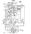
- FIG. 3 the circuit 5 for analyzing the selected values N that it receives from the circuit 4 in FIG. 1 is detailed.
- This analysis circuit 5 essentially comprises an addressable memory 50 in which the accounts relating to the values N to Y15 are stored respectively, a circuit 51 for calculating each of these accounts, an output circuit 52 providing on an output, which constitutes the output 3 of the device, the numerically defined value of the evaluated noise level iB, and a control circuit 53 controlling the circuit 51 for calculating the accounts and the output circuit 52.
- the memory 50 has a "data" input connected to the output of the circuit 51 for calculating the respective accounts. It has a 3 / W read and write control input connected to the output of a door logic "no and" 55 which receives on the one hand the clock signal H and on the other hand the signal V 2 ; by the level “1" on its output, this gate 55 controls the reading of the memory 50 while by the level “o” on its output it commands the preparation of a write operation in the memory, operation which will be carried out on the first next transition from this level "o" to level "1".
- the memory 50 also has an addressing command input Ad on which is applied the sequence signal S 2 defining the sequences s 2 each flowing over 16 periods of the signal H and consisting of a series of numbers from 0 to 15 that is to say from the series of codes assigned to the values N o to N 15 scrolling at the sampling rate, on each interval I the first sequence s 2 which takes place there starting with the second sampling period .
- the signal V 2 is at level "1" during the course of the second sequence s 2 over each interval I and at level "o" the rest of the time.
- the writing operations in the memory 50 are thus carried out for each interval I during the course of the second sequence s 2 ; during the rest of the time, the memory 50 is constantly constantly reading.
- the control circuit 53 is connected to the outputs of circuit 4 (FIG. 1 or 2) to receive the logic signal L and the selected values N and to the output of circuit 52 (or at the output of the device) to receive the value of the level noise rating NB. It is also connected to the output of memory 50 through a register 54 controlled by the clock signal H inverted in a reverse logic gate 56, to receive the stored accounts. It also receives the clock signal H, the sequence signal S 2 and the signal V 1 at level "1" during the course of the first sequence s 2 over each interval I and at level "o" during the rest of the time.
- This control circuit 53 essentially comprises four comparators 530 to 533 and two D-type flip-flops 534 and 535.
- the comparators 530 and 531 each receive on a first input connected to the second output of circuit 4 (FIGS. 1 and 2) the selected values N and on a second input the sequence signal S2, with regard to the comparator 530, and the noise level value code! 1B, for comparator 531.
- Each of these two comparators delivers a logic signal L or L 1 , according to the comparator 530 or 531 considered, at the level "1" or "o” depending on whether the codes received on its two inputs are equal or not.
- the comparators 532 and 533 are threshold comparators which each receive from the register 54 the accounts stored in the memory 50 and compare them one, that is the comparator 532, with the high threshold fixed for all the accounts and the other 533, with the low threshold set for all accounts.
- R h and R b These high and low thresholds mentioned above during the description of FIG. 1 are designated by R h and R b ; they are chosen close respectively to the upper and lower limits between which one chooses to maintain the evolution of the accounts and their introduction is intended to allow the maintenance of the accounts between these limits.
- Each of these last two comparators 532 and 533 delivers a logic signal L 2 or L 3 , depending on the comparator considered, at level “1" or "o” depending on whether or not the stored account received exceeds its threshold.
- the two D type flip-flops 534 and 535 have their inputs "D" connected to the outputs of comparators 531 and 532 respectively. They are clocked by the clock signal H validated by the output signal of a logic gate “and” 536 of circuit 53, the output signal of this gate “and” being applied to each of these two flip-flops on an input clock validation Val and the clock signal H on their clock input Cp.
- the gate 536 has an input connected to the output of the comparator 530 and receives on another input the signal V,; its output signal thus validates the clock signal H during the course of the first sequence s 2 of each interval I when the memory 50 delivers the account concerning that of the values N to N ? 5 whose code is delivered by the circuit 4 ( Figures 1 and 2) and applied to the first inputs of the comparators 530 and 531.
- This calculation circuit 51 is composed of a circuit for defining the account increment 510 receiving the five signals L, L o , L ⁇ 1 L'2 and L 3 and a summing circuit 511 connected to the output of the circuit 510.
- This 510 definition circuit account increment delivers in response to its five input signals, a positive, negative or zero increment value, defined according to a determined law. It is this increment value which is applied to the summing circuit 511 on one of its inputs.
- the other input of this summing circuit 511 is connected through the register 54 to the output of the memory 50, while its output which constitutes that of the calculation circuit 51 is connected to the input of the memory 50.
- the output circuit 52 is composed of two registers 520 and 521.
- the register 520 receives as input the sequence signal S 2 with a view to memorizing the code defined by this signal S 2 when the account concerns that of the values N to N 15 thus coded exceeds said high threshold.
- the register 521 is arranged following the register 520. These two registers 520 and 521 are both clocked by the clock signal H applied to their clock input C. This clock signal H is validated, with regard to the register 520, by the signal L 2 of output from the comparator 532 applied to its clock validation input Val and, with regard to the register 521, by the signal C 2 applied to its Val validation input Val.
- This signal C 2 is on each interval I, at the level "1" during the sampling period where the second sequence s 2 starts, that is to say the eighteenth sampling period on this interval, and at level "o" otherwise.
- the code present in register 520 at the end of this eighteenth sampling period is then transferred to register 521 which applies it to output 3 of the device.
- Table II indicates the different account increment values defined by the circuit 510 in response to the logic signals it receives.
- the non-zero increment values specified therein correspond to a ceiling of the order of 255 for accounts expressed on eight bits.
- the increment definition circuit has 510 consists, for example, a PROM memory delivering the increment values expressed in eight bits using supplements to 2 ê for negative values.
- the summing circuit 511 then consists of a simple adder with two eight-bit inputs and one eight-bit output.
- the thresholds R h and R b of the comparators 532 and 533 are chosen for example equal to 247 and 7 respectively, and these two comparators are then a simple logic circuit "and" with 5 inputs and a simple logic circuit "or” with 5 inputs , respectively, each receiving only the five most significant bits of the stored accounts.
- the memory 50 is alternately write and read during the only second sequence s 2 , which takes place at the sampling rate, of each interval I ; it is read only p en- ing the other sequences s 2, which are also held in the sampling rate of each interval I.
- the output signal L 2 of this comparator goes to level "1" and validates the clock signal H applied to the register 520.
- This register 520 samples the sequence signal S 2 at the end of the period of the signal H during which this account is delivered by the memory 50, in order to store the code of that of the values N o to N 15 concerned .
- the register 520 therefore contains either what is the most general case, the code of the single value among the values N to N 15 for which the count exceeds the high threshold R n , or , where appropriate, the code of the largest of those of the values N o to N 15 whose accounts exceed the high threshold except possibly with regard to the time intervals I of a period of start-up of the device, c '' that is to say following the power-up of the device, where this register may contain the code of a particular value that an initialization command, not shown, will have written this same command there also ensuring the setting to zero of memory 50.
- the account increment definition circuit 510 delivers in response to these signals the corresponding account increment value, according to the preceding table II.
- the updated account concerning the value N j-1 is then available at the output of the adder 511 and is written to memory 50 during the writing operation which takes place on the rising edge of the clock signal H marking the end of this jth period.
- this count is increased by four units, or possibly by five units if this value N is equal to the value present on output 3 of the device during the first sequence s 2 of the interval I considered which in practice can only occur during a period of start-up of the device, while none of the other counts are modified.
- the timing circuit 6 of FIG. 1 is detailed, elaborating from the clock signal H that it receives the different signals C 1 and S 1 applied to the circuit 4 for evaluation and selection of the values of the signal level present on the channel and C 2 , V JY Y 2 and S 2 applied to the circuit 5 for analysis of the selected values.
- the timing circuit 6 is described in the context of the numerical example considered above, in particular with regard to Figures 2 and 3. It includes a counter 60 receiving as input the clock signal H applied to the input 2 of the device, a register 61 receiving the successive states of the counter 60 which it delays by a period of the clock signal H. and a decoder 62 receiving the successive states of the counter 60 with the delay introduced by the register 61.
- the counter 60 is a counter by 128. It outputs the states 0 to 127 defined on seven bits, at the sampling rate in a duration equal to each time interval I, ie 16 ms. It develops the timing signal C 1 taking the level "1" for its output state o and the level "ott for any other state, which defines the successive time intervals I.
- This signal C 1 which is illustrated delivered on an output independent of the counter can be obtained on the output of a "non-outt" logic gate receiving as input the successive states taken by the counter.
- It also elaborates the sequence signal S 1 which defines the sequence s 1 over each time interval I, dividing each time interval I into eight equal sub-intervals for the evolution of the absolute value of the step of variation p of the value comparison n.
- This signal of sequence S 1 is defined by the three most significant bits of the successive states of the counter and each sequence s 1 therefore consists of a series of eight numbers, from o to 7, scrolling regularly over the time interval I considered.
- the register 61 receives the seven bits defining the successive states taken by the counter and the clock signal H on its clock input Cp to produce as output the sequence signal S 2 which defines the sequences s 2 in the duration of each interval I
- This sequence signal S 2 is defined by the four least significant bits of the states of the counter delivered with the delay of one period of the clock signal at the output of the register. It therefore defines eight sequences s 2 on each inter valle I, the first sequence starting with the delay indicated either on the second sampling period of the time interval I considered, each consisting subsequently of the numbers 0 to 15 scrolling at the sampling rate.
- the decoder 62 receives the seven bits defining the successive states of the counter with the delay introduced by the register 61. It is arranged to deliver the signal V1 at level "1" for the states 0 to 15 of the counter 60 which it receives from the register 61 and at level "o” for the other states and the signal V 2 at level “1” for the states 16 to 31 that it receives and at level "o” for the other states. These two signals V 1 and V 2 therefore respectively select the first and the second of the sequences s 2 contained in the aforementioned sequence signal S 2 .
- This decoder 62 is further arranged to deliver the timing signal C 2 at level "1" for the state 16 of the counter 60 which it receives from the register 61 and at the level "o" for all the other states which it receives , that is to say of the same duration as the signal C 1 but starting with the second sequence s 2, that is to say shifted from the signal C 1 by seventeen periods of the clock signal.
- This decoder 62 can also be formed using a PROM memory.
- the noise present during the short intersyllabic pauses contributes to the evaluation of the noise level.
- This provides a short acquisition time, variable from 1 to 4 or 5 seconds in the encrypted example described above, even when the processed channel carries, in addition to the useful speech signals, echo signals.
- the evaluation of the signal level present on the telephone channel could be done, with regard to the noise level range (?), Directly using the discrete values C ⁇ y to N_ .) that we define in this range for the evaluation of the noise level, the transcoding operation carried out by the selection circuit (41) in the example embodiment described then not being useful.
- analog circuits could be used for the evaluation of the level of the signal present on the telephone channel in particular, this signal being for example available on the channel in analog form.
Abstract
Selon l'invention, on évalue le niveau du signal présent sur la voie sur des intervalles de temps successifs, on sélectionne celles des valeurs de niveau comprises dans une plage de niveau de bruit donnée, on les exprime à l'aide de r valeurs discrètes de cette plage, et on calcule les comptes donnant la répartition des valeurs sélectionnées entre les différentes valeurs discrètes pour prendre comme valeur de niveau de bruit celle des valeurs discrètes sur laquelle se concentre la majorité des valeurs sélectionnées.According to the invention, the level of the signal present on the channel is evaluated over successive time intervals, those of the level values included in a given noise level range are selected, they are expressed using r discrete values. of this range, and the accounts giving the distribution of the selected values between the different discrete values are calculated to take as noise level value that of the discrete values on which the majority of the selected values are concentrated.
Description
La présente invention est relative à la transmission téléphonique et concerne l'évaluation du niveau de bruit sur une voie téléphonique. Elle vise plus particulièrement à résoudre le problème d'une telle évaluation à partir des signaux présents sur la voie en service, c'est-à-dire à partir de signaux constitués de signaux de parole (ou de signalisation) auxquels se superpose le bruit, séparés par des intervalles de silence occupés par le seul bruit.The present invention relates to telephone transmission and relates to the evaluation of the noise level on a telephone channel. It more particularly aims to solve the problem of such an evaluation on the basis of the signals present on the channel in service, that is to say on the basis of signals consisting of speech (or signaling) signals to which the noise is superimposed. , separated by intervals of silence occupied only by noise.
On trouve une application particulière de l'invention dans la détection de parole, par exemple dans un dispositif de concentration de signaux téléphoniques par interpolation de la parole, ou bien encore dans la génération de bruit dit d'agrément destiné, dans un réseau téléphonique où les chemins de transmission entre abonnés en communication sont temporairement interrompus, par exemple à des fins de suppression d'écho ou de concentration, à limiter la perception de ces interruptions par les abonnés.There is a particular application of the invention in the detection of speech, for example in a device for concentrating telephone signals by interpolation of speech, or even in the generation of so-called amenity noise intended, in a telephone network where the transmission paths between subscribers in communication are temporarily interrupted, for example for the purpose of echo cancellation or concentration, to limit the perception of these interruptions by the subscribers.
On sait que les dispositifs de concentration de signaux téléphoniques par interpolation de la parole, qui équipent certaines liaisons téléphoniques multivoie, augmentent les capacités de ces liaisons en évitant la transmission des silences des conversations. Ils comportent donc des détecteurs de parole pour repérer les périodes de parole et les périodes de silence sur chacune des voies à concentrer. Les performances de ces dispositifs de concentration sont directement tributaires de la qualité de la discrimination parole/silence effectuée par ces détecteurs de parole. En particulier, il est souhaitable que ces détecteurs de parole présentent une grande insensibilité au bruit afin de permettre un taux de concentration élevé, tout en étant très sensibles aux signaux de parole_afin d'éviter un hachage de la parole.It is known that the devices for concentrating telephone signals by speech interpolation, which equip certain multi-channel telephone links, increase the capacities of these links by avoiding the transmission of silence in conversations. They therefore include speech detectors to identify speech periods and periods of silence on each of the channels to be concentrated. The performance of these concentration devices is directly dependent on the quality of the speech / silence discrimination carried out by these speech detectors. In particular, it is desirable that these speech detectors have a high insensitivity to noise in order to allow a high concentration rate, while being very sensitive to speech signals in order to avoid hashing of speech.
Il est connu de détecter. un signal de parole sur une voie de transmission téléphonique à partir essentiellement du niveau du signal présent sur la voie surveillée. Ainsi, tout signal sur la voie surveillée dont le niveau sur un intervalle de temps est supérieur à un seuil placé au-dessus du niveau de bruit sur la voie est présumé être un signal de parole et le reste du silence. En vue d'effectuer une telle détection de signal de parole sur une voie, il est connu d'élaborer un signal représentatif du niveau moyen sur un intervalle de temps élémentaire du signal présent sur la voie et de comparer ce signal élaboré à un seuil supérieur au niveau de bruit sur la voie. En vue d'effectuer une telle détection de signal de parole sur une voie, il est également connu de comparer l'amplitude de chaque échantillon du signal présent sur la voie surveillée, échantilloné à la cadence de 8 kHz, à un seuil supérieur au niveau de bruit sur la voie, d'attribuer à chaque échantillon une note algébrique fonction du résultat de la comparaison et de cumuler les notes attribuées aux échantillons successifs afin d'effectuer la discrimination parole/silence à partir de ce cumul.It is known to detect. a speech signal on a telephone transmission channel essentially from the level of the signal present on the monitored channel. Thus, any signal on the monitored channel whose level over a time interval is greater than a threshold placed above the noise level on the channel is presumed to be a speech signal and the rest of the silence. In order to carry out such a detection of speech signal on a channel, it is known to develop a signal representative of the average level over an elementary time interval of the signal present on the channel and to compare this signal produced with a threshold higher than the noise level on the channel. In order to perform such a speech signal detection on a channel, it is also known to compare the amplitude of each sample of the signal present on the monitored channel, sampled at the rate of 8 kHz, at a threshold greater than the level of noise on the channel, to assign to each sample an algebraic score depending on the result of the comparison and to cumulate the scores attributed to the successive samples in order to discriminate speech / silence from this cumulation.
Il est parfois pris comme référence de niveau de bruit, en vue de la détermination du seuil de comparaison intervenant dans une telle détection de signal de parole, le niveau maximal de bruit admis par le CCITT pour une voie téléphonique, soit -40 dBmo. Toutefois, le niveau de bruit sur une voie téléphonique peut différer sensiblement de cette valeur et une meilleure discrimination parole/silence peut être obtenue en évaluant le niveau de bruit sur la voie surveillée et faisant varier le seuil de comparaison en fonction du niveau de bruit évalué, ainsi qu'il a été aussi déjà proposé.It is sometimes taken as a noise level reference, for the purpose of determining the comparison threshold involved in such a speech signal detection, the maximum noise level admitted by the CCITT for a telephone channel, ie -40 dBmo. However, the noise level on a telephone channel can differ significantly from this value and better speech / silence discrimination can be obtained by evaluating the noise level on the monitored channel and varying the comparison threshold according to the evaluated noise level. , as has already been proposed.
L'évaluation du niveau de bruit sur une voie téléphonique est également utile pour la génération de bruit d'agrément dans certains réseaux téléphoniques. Ainsi, on sait qu'au cours d'une communication téléphonique passant sur un circuit quatre fils muni de suppresseurs d'écho, lorsqu'un seul des abonnés en communication parle, la voie que définit le circuit quatre fils pour la transmission dans le sens de l'abonné récepteur qui se tait vers l'abonné qui parle est coupée en vue de bloquer la propagation de signaux d'écho. Il est connu d'injecter alors sur cette voie, en aval de la coupure, un bruit d'agrément destiné à compenser la contribution au bruit de fond normalement perçu par l'abonné récepteur pour ce sens de transmission, des équipements du réseau desquels cet abonné est déconnecté du fait de cette coupure. Une évaluation du niveau de cette contribution et une adaptation du niveau du bruit d'agrément au résultat de cette évaluation permettent d'obtenir une bonne compensation en niveau et, par là-même, de limiter sensiblement la perception de telles coupures qui nuirait au bon déroulement de la conversation.Evaluating the noise level on a telephone channel is also useful for generating pleasant noise in certain telephone networks. Thus, it is known that during a telephone call from a son four system equipped with sup p yclic echo when one speaks of communication subscribers, the path that defines the four son circuitry for transmission in the direction of the receiving subscriber who is silent towards the speaking subscriber is cut off in order to block the propagation of echo signals. It is known to then inject on this channel, downstream of the cutoff, an approval noise intended to compensate for the contribution to the background noise normally perceived by the receiving subscriber for this direction of transmission, of the network equipment from which this subscriber is disconnected due to this interruption. An evaluation of the level of this contribution and an adaptation of the level of the pleasant noise to the result of this evaluation makes it possible to obtain a good level compensation and, thereby, to limit significant the perception of such cuts which would hinder the smooth running of the conversation.
Le problème de limitation de la perception des interruptions temporaires des chemins de transmission entre abonnés en communication se pose également, ainsi qu'on le sait, dans les réseaux téléphoniques équipés de dispositifs de concentration par interpolation de la parole. Dans de tels dispositifs, l'évaluation du niveau de bruit sur une voie peut être utilisée à la fois à des fins de détection de parole et à des fins de génération de bruit d'agrément.The problem of limiting the perception of temporary interruptions of the transmission paths between subscribers in communication also arises, as is known, in telephone networks equipped with devices for concentrating by speech interpolation. In such devices, the evaluation of the noise level on a channel can be used both for speech detection purposes and for the purpose of generating pleasant noise.
Le problème essentiel à résoudre, lorsque l'on veut évaluer le niveau du bruit sur une voie téléphonique à partir des signaux présents sur la voie en service, est d'éviter que les signaux de parole acheminés par cette voie, dont certains peuvent être de niveau très faible, ne faussent l'opération. Pour résoudre ce problème, il est proposé dans le document FR-A 2 451 680, qui décrit un circuit d'évaluation du niveau de bruit sur une voie téléphonique intégré au sein d'un détecteur de parole, d'utiliser deux filtres de moyenne, un premier à bande relativement étroite et un second à bande très étroite. Ces deux filtres traitent le signal présent sur la voie en traitement pendant les périodes de silence repérées par le détecteur de parole ; le premier traite en outre le signal présent sur cette voie pendant les périodes d'activité repérées par le détecteur de parole tandis que le second est alors constamment initialisé au double de la valeur du signal de sortie du premier. Le niveau de bruit sur la voie est évalué à la dernière valeur commune de convergence de ces deux filtres. Une telle façon de procéder se fonde sur le fait que le bruit de fond sur une voie téléphonique est généralement assez stationnaire à l'opposé des signaux de parole qui présentent un caractère non stationnaire. Dans ces conditions, les deux filtres, dont les constantes de temps équivalentes sont voisines respectivement de 8 ms et 0,128 ms, ne convergent vers une même valeur que lorsqu'un bruit de fond a été seul présent sur la voie pendant une durée relativement longue ; cette valeur commune de convergence traduit alors le niveau moyen de bruit.The essential problem to be solved, when one wants to assess the noise level on a telephone channel from the signals present on the channel in service, is to avoid the speech signals routed by this channel, some of which may be of very low level, do not distort the operation. To solve this problem, it is proposed in document FR-
Pour résoudre ce même problème, une autre solution, se fondant également sur ces caractères différents des signaux de parole et du bruit de fond sur une voie téléphonique, est décrite dans le document FR-A 2 482 389. Selon ce document, un circuit de calcul de moyenne élabore une représentation du niveau moyen du signal présent sur la voie en traitement sur un intervalle de temps élémentaire. Deux circuits de prélèvement et d'enregistrement extraient et conservent l'un la valeur maximale l'autre la valeur minimale de cette représentation, ces deux circuits étant réinitialisés à une même cadence variable de période longue par rapport à l'intervalle élémentaire. Un comparateur compare entre elles les valeurs maximale et minimale fournies par les deux circuits de prélèvement et d'enregistrement, afin de repérer les moments où ces deux valeurs satisfont à une relation donnée traduisant un faible écart relatif entre elles. Le niveau de bruit est alors obtenu à partir des valeurs minimales de la représentation pour lesquelles cette relation est satisfaite. Pour ces opérations, la constante de temps équivalente du circuit de calcul de moyenne est de 16 ms et la réinitialisation des deux circuits de prélèvement et d'enregistrement s'effectue à une cadence plus rapide lorsque la voie est présumée être inactive que lorsque celle-ci est présumée être active, toutes les 256 ms et toutes les 2 s respectivement, ces états présumés de la voie correspondant à des états d'une machine séquentielle dont l'évolution s'effectue sous la commande de paramètres fonction de la représentation du niveau moyen du signal présent sur la voie, dans la détermination desquels intervient le niveau de bruit évalué.To solve this same problem, another solution, also relying on these characters different from speech signals and noise background on a telephone channel, is described in document FR-A 2 482 389. According to this document, an averaging circuit develops a representation of the average level of the signal present on the channel in processing over an elementary time interval. Two sampling and recording circuits extract and keep one the maximum value the other the minimum value of this representation, these two circuits being reset at the same variable rate of long period relative to the elementary interval. A comparator compares the maximum and minimum values provided by the two sampling and recording circuits with each other, in order to identify the moments when these two values satisfy a given relationship reflecting a small relative difference between them. The noise level is then obtained from the minimum values of the representation for which this relation is satisfied. For these operations, the equivalent time constant of the averaging circuit is 16 ms and the reinitialization of the two sampling and recording circuits is carried out at a faster rate when the channel is presumed to be inactive than when it these are presumed to be active, every 256 ms and every 2 s respectively, these presumed channel states corresponding to states of a sequential machine whose evolution takes place under the command of parameters depending on the level representation means of the signal present on the channel, in the determination of which the evaluated noise level intervenes.
Avec l'une ou l'autre de ces deux solutions, l'évaluation du niveau de bruit ne se fait qu'au cours des intervalles de silence assez longs. Ceci peut conduire à des temps d'acquisition très grands, tout particulièrement dans le cas où se propagent sur la voie non seulement des signaux de parole d'un abonné émettant dans cette voie mais également des signaux d'écho des signaux de parole du correspondant de cet abonné, l'évaluation du niveau de bruit ne se faisant alors que lorsque les deux abonnés se taisent pendant une durée appréciable. De plus ces deux solutions impliquent un repérage des périodes de parole et de silence faisant appel à des agencements complexes, lourds dans le cadre d'une application autre que la détection de parole.With either of these two solutions, the noise level is only evaluated during fairly long intervals of silence. This can lead to very long acquisition times, especially in the case where not only speech signals from a subscriber transmitting on this channel are propagated on the channel, but also echo signals from the correspondent's speech signals. of this subscriber, the assessment of the noise level then being made only when the two subscribers are silent for an appreciable duration. In addition, these two solutions involve tracking speech and silence periods using complex arrangements, heavy in the context of an application other than speech detection.
La présente invention a pour but de remédier à ces inconvénients en permettant une évaluation rapide et précise du niveau de bruit sur une voie téléphonique au moyen d'un agencement simple.The object of the present invention is to remedy these drawbacks by allowing rapid and precise evaluation of the noise level on a telephone route by means of a simple arrangement.
Elle a pour objét un procédé d'évaluation du niveau de bruit sur une voie téléphonique, à partir de l'évaluation du niveau du signal présent sur cette voie sur des intervalles de temps successifs sensiblement de même durée, consistant à :
- - attribuer au niveau de bruit sur cette voie une plage donnée dite plage de niveau de bruit dans laquelle s'étend un ensemble défini limité de valeurs discrètes de niveau,
- - sélectionner les valeurs successives de niveau de signal présent sur la voie tombant dans ladite plage de niveau de bruit
- - et tenir une comptabilité relative des différentes valeurs sélectionnées exprimées à l'aide desdites valeurs discrètes pour prendre comme représentative du niveau de bruit sur la voie celle des valeurs discrètes sur laquelle se concentre la majorité des valeurs de niveau de signal sélectionnées.
- - assign to the noise level on this channel a given range called the noise level range in which a limited defined set of discrete level values extends,
- - select the successive values of signal level present on the channel falling in said noise level range
- - And keep relative accounts of the different selected values expressed using said discrete values to take as representative of the noise level on the channel that of the discrete values on which the majority of the selected signal level values are concentrated.
Avantageusement, dans la comptabilité relative des valeurs sélectionnées, chaque valeur sélectionnée est pondérée plus ou moins fortement selon qu'elle est égale ou non à la valeur courante du niveau de bruit évalué.Advantageously, in the relative accounting of the selected values, each selected value is weighted more or less strongly depending on whether or not it is equal to the current value of the evaluated noise level.
La présente invention a également pour objet un dispositif de mise en oeuvre du procédé précité. Ce dispositif comporte :
- - un circuit d'évaluation du signal présent sur la voie téléphonique sur les intervalles de temps successifs I sensiblement de même durée,
- - un circuit de sélection sélectionnant, parmi les valeurs de niveau de signal présent sur la voie qu'il reçoit du circuit d'évaluation , les seules valeurs comprises dans une plage de niveau donnée attribuée au bruit et dite plage de niveau de bruit et les délivrant exprimées à l'aide d'un ensemble limité défini de r valeurs discrètes,
- - un circuit d'analyse des valeurs sélectionnées délivrées par le circuit de sélection , sensible à la répartition desdites valeurs sélectionnées entre lesdites valeurs discrètes , repérant celle des valeurs discrètes sur laquelle se concentre la majorité des valeurs sélectionnées pour la délivrer sur une sortie en tant que valeur représentative du niveau de bruit,
- - et un circuit de cadencement des circuits d'évaluation et de-sélection de niveau de signal présent sur la voie ainsi que du circuit d'analyse pour la détermination de la valeur du niveau de bruit au rythme desdits intervalles de temps I définis par ce circuit de cadencement.
- a circuit for evaluating the signal present on the telephone channel over successive time intervals I of substantially the same duration,
- a selection circuit selecting, from the signal level values present on the channel it receives from the evaluation circuit, the only values included in a given level range attributed to the noise and called the noise level range and the delivering expressed using a defined limited set of r discrete values,
- a circuit for analyzing the selected values delivered by the selection circuit, sensitive to the distribution of said selected values between said discrete values, identifying that of the discrete values on which the majority of the selected values focus to deliver it to an output as that value representative of the noise level,
- - and a timing circuit for the signal level evaluation and selection circuits present on the channel as well as the circuit analysis for determining the value of the noise level at the rate of said time intervals I defined by this timing circuit.
Selon un mode particulier de réalisation, le circuit d'analyse des valeurs sélectionnées comporte :
- - une mémoire adressable adressée sous le contrôle d'un signal de séquence élaboré par ledit circuit de cadencement, mémorisant pour les r valeurs discrètes r comptes respectivement traduisant la répartition des valeurs sélectionnées délivrées par le circuit de sélection entre les r valeurs discrètes,
- - un circuit de calcul des comptes comportant d'une part un circuit de définition d'incrément de compte et d'autre part un circuit sommateur ayant deux entrées reliées à la sortie de la mémoire et à la sortie dudit circuit de définition d'incrément de compte respectivement et une sortie reliée à l'entrée de ladite mémoire,
- - un circuit de commande comportant des circuits comparateurs comparant, pour chaque valeur sélectionnée délivrée par le circuit de sélection, d'une part les différentes valeurs discrètes reçues en concordance avec l'adressage de ladite mémoire avec la valeur sélectionnée considérés pour identifier le compte mémorisé concerné par cette valeur sélectionnée et d'autre part les différents comptes mémorisés avec un seuil haut et un seuil bas de compte préétablis, commandant, dans ledit circuit de définition d'incrément de compte, pour chaque valeur sélectionnée délivrée par le circuit de sélection, le choix d'une valeur d'incrément positive pour le seul compte concerné par la valeur sélectionnée considérée si celui-ci ne dépasse pas ledit seuil haut ou d'une valeur d'incrément négative pour les autres comptes supérieurs audit seuil bas si ce compte concerné par la valeur sélectionnée considérée dépasse ledit seuil haut
- - et un circuit de sortie de la valeur de niveau de bruit commandé par ledit circuit de commande lors de la détection du dépassement dudit seuil haut par l'un des comptes mémorisés, recevant la valeur discrète concernée par ce compte dépassant ledit seuil haut.
- an addressable memory addressed under the control of a sequence signal produced by said timing circuit, storing for the r discrete values r counts respectively reflecting the distribution of the selected values delivered by the selection circuit between the r discrete values,
- a circuit for calculating the accounts comprising on the one hand an account increment definition circuit and on the other hand a summing circuit having two inputs connected to the output of the memory and to the output of said increment definition circuit account respectively and an output connected to the input of said memory,
- a control circuit comprising comparator circuits comparing, for each selected value delivered by the selection circuit, on the one hand the different discrete values received in accordance with the addressing of said memory with the selected value considered to identify the stored account concerned by this selected value and on the other hand the different accounts memorized with a high threshold and a low threshold of account pre-established, commanding, in said circuit of definition of account increment, for each selected value delivered by the selection circuit, the choice of a positive increment value for the only account concerned by the selected value considered if it does not exceed said high threshold or of a negative increment value for other accounts above said low threshold if this account concerned by the selected value considered exceeds said high threshold
- - And an output circuit of the noise level value controlled by said control circuit upon detection of the exceeding of said high threshold by one of the stored accounts, receiving the discrete value concerned by this account exceeding said high threshold.
Les caractéristiques et avantages de la présente invention apparaîtront plus clairement au cours de la description d'un mode de réalisation donné à titre d'exemple et illustré dans les dessins joints. Dans ces dessins :
- - la figure 1 est un diagramme synoptique d'un dispositif d'évaluation de niveau de bruit selon l'invention,
- - la figure 2 est un schéma d'un circuit d'évaluation et de sélection des valeurs du niveau de signal sur la voie, utilisé dans la figure 1,
- - la figure 3 est un schéma d'un circuit d'analyse des valeurs sélectionnées du niveau de signal sur la voie, utilisé dans la figure 1,
- - la figure 4 est un schéma d'un circuit de cadencement, également utilisé dans la figure 1,
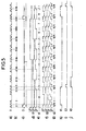
- - la figure 5 illustre dans le temps, des signaux délivrés par le circuit de cadencement utilisé dans la figure 1 et donné dans la figure 4.
- FIG. 1 is a block diagram of a noise level evaluation device according to the invention,
- FIG. 2 is a diagram of a circuit for evaluating and selecting the values of the signal level on the channel, used in FIG. 1,
- FIG. 3 is a diagram of a circuit for analyzing the selected values of the signal level on the channel, used in FIG. 1,
- FIG. 4 is a diagram of a timing circuit, also used in FIG. 1,
- FIG. 5 illustrates over time signals delivered by the timing circuit used in FIG. 1 and given in FIG. 4.
Le dispositif d'évaluation du niveau de bruit illustré dans les dessins est de type numérique. Il est prévu pour traiter un signal de voie téléphonique disponible sous forme d'échantillons numériques successifs. Pour la simplicité de la présentation, il ne traite qu'une seule voie. Bien entendu, il pourrait être adapté au traitement en temps partagé d'une pluralité de voies.The noise level evaluation device illustrated in the drawings is of the digital type. It is intended to process an available telephone channel signal in the form of successive digital samples. For the simplicity of the presentation, it deals with only one way. Of course, it could be adapted to the time-sharing processing of a plurality of channels.
Pour des raisons de simplicité de présentation également, dans ces figures les liaisons acheminant des signaux numériques définis par des mots binaires à plusieurs bits en parallèle ont été représentées par un trait fort, plus épais que celles acheminant des signaux binaires. Le nombre de bits en parallèle transmis sur ces liaisons en trait fort sera précisé au fur et à mesure de la description des figures, donnée en regard d'exemples chiffrés.For reasons of simplicity of presentation also, in these figures the links carrying digital signals defined by binary words with several bits in parallel have been represented by a strong line, thicker than those carrying binary signals. The number of bits in parallel transmitted on these links in strong lines will be specified as the description of the figures is given, given with regard to encrypted examples.
On précise encore qu'il est utilisé dans la description ci-après des références constituées d'une lettre affectée d'un indice ; par commodité la lettre et l'indice de telles références apparaissent dans les figures au même niveau.It should also be noted that in the description below, references consisting of a letter with an index are used; for convenience, the letter and the index of such references appear in the figures at the same level.
Le dispositif selon l'invention illustré dans la figure 1 présente une entrée 1 sur laquelle sont appliqués en parallèle les bits définissant l'amplitude des échantillons numériques du signal présent sur une voie téléphonique à traiter, indépendamment de la polarité de ces échantillons, une entrée 2 sur laquelle est appliqué un signal d'horloge H à la cadence d'échantillonnage et une sortie 3 sur laquelle est disponible la valeur du niveau de bruit évalué, soit NB, également définie sous forme numérique. Il comporte un circuit 4 d'évaluation et de sélection des valeurs du niveau du signal présent sur la voie, relié à ses deux entrées 1 et 2, un circuit 5 d'analyse des valeurs sélectionnées délivrées par le circuit 4, disposé à la suite de ce circuit 4 et relié, en outre, à l'entrée 2 pour recevoir le signal d'horloge H, fournissant la valeur du niveau de bruit évalué NB sur la sortie 3, et un circuit 6 de cadencement élaborant à partir du signal d'horloge H qu'il reçoit de l'entrée 2 différents signaux de cadencement précisés ci-après, qui sont nécessaires au bon fonctionnement des circuits 4 et 5.The device according to the invention illustrated in FIG. 1 has an
Le circuit 4 évalue le niveau du signal présent sur la voie téléphonique sur des intervalles de temps I successifs de même durée, longue par rapport à la période du signal d'horloge H à la cadence d'échantillonnage, et sélectionne celles des valeurs de niveau de ce signal tombant dans une plage donnée P considérée comme la plage des valeurs possibles de niveau de bruit et dite plage de niveau de bruit. Il fournit, sur une première sortie, un signal logique L indiquant pour chaque valeur de niveau de ce signal si celle-ci tombe ou non dans la plage P et, sur une deuxième sortie, chacune des valeurs de niveau de ce signal tombant dans la plage P, ces valeurs tombant dans la plage P et désignées par N étant exprimées à l'aide d'un ensemble limité de r différentes valeurs désignées N à N ... Pour ce faire, le circuit 4 se compose d'un circuit d'évaluation de niveau 40 qui reçoit les bits des échantillons appliqués à l'entrée 1 c'est-à-dire des échantillons du signal présent sur la voie téléphonique, et d'un circuit de sélection 41 qui reçoit les valeurs de niveau élaborées par le circuit 40 et sélectionne celles des valeurs qui tombent dans la plage P. Le circuit 40 évaluant le niveau du signal présent sur la voie, en ce qui concerne la plage P, à l'aide ici d'un ensemble de valeurs en nombre supérieur à r, le circuit de sélection 41 assure en outre ici un transcodage des valeurs qu'il sélectionne, permettant de les exprimer à l'aide des r valeurs M 0 à Nr-l*Circuit 4 evaluates the level of the signal present on the telephone channel over successive time intervals I of the same duration, long with respect to the period of the clock signal H at the sampling rate, and selects those of the level values. of this signal falling in a given range P considered as the range of possible noise level values and called noise level range. It provides, on a first output, a logic signal L indicating for each level value of this signal whether or not it falls within the range P and, on a second output, each of the level values of this signal falling in the range range P, these values falling in the range P and designated by N being expressed using a limited set of r different values designated N to N ... To do this, circuit 4 consists of a circuit
Le circuit 4 reçoit du circuit de cadencement 6 un signal de cadencement C1 définissant les intervalles T_ et un signal de séquence 31 définissant des séquences identiques s1 chacune se déroulant sur tout un intervalle I et y définissant différentes phases de fonctionnement du circuit 4 qui seront précisées ci-après au cours de la description détaillée de ce circuit donnée en regard de la figure 2.The circuit 4 receives from the timing circuit 6 a timing signal C 1 defining the intervals T_ and a
Ces intervalles de temps I sur lesquels s'effectue l'évaluation du niveau du signal présent sur la voie téléphonique sont de durée choisie longue par rapport à la période de la fréquence limite inférieure de la bande passante, soit longue par rapport à 3p0 s 3,3 ms, et courte par rapport au temps moyen d'établissement ou chute des syllabes qui est de l'ordre d'une quarantaine de millisecondes.These time intervals I over which the evaluation of the level of the signal present on the telephone channel is carried out are of duration chosen to be long with respect to the period of the lower limit frequency of the bandwidth, ie long with respect to 3 p 0 s 3.3 ms, and short compared to the average time to establish or drop the syllables which is of the order of forty milliseconds.
Le circuit 5 d'analyse des valeurs sélectionnées N qu'il reçoit du circuit 4 est sensible à leur répartition entre les différentes valeurs N à N r-1 La majorité de ces valeurs sélectionnées N est en fait généralement concentrée sur l'une des valeurs No à N r-1 et c'est cette dernière valeur qui est repérée par le circuit 5 et considérée comme significative du niveau de bruit sur la voie. En effet, lorsque le signal présent sur la voie téléphonique n'est constitué que d'un bruit de fond, l'évaluation faite par le circuit 4 du niveau de ce signal fournit des valeurs de niveau qui tombent dans la plage P et sont donc sélectionnées et qui s'avèrent très peu dispersées (du fait du caractère quasi "stationnaire" du bruit), en général concentrées principalement sur l'une des valeurs No à N r-1 et secondairement sur les deux valeurs adjacentes ou le cas échéant l'unique valeur adjacente à celle-ci. Lorsque, par contre, un signal de parole se superpose au bruit, les valeurs de niveau du signal sur la voie téléphonique, qui soit tombent hors de la plage de niveau P et sont donc ignorées par le circuit 5 soit tombent dans la plage P mais s'avèrent très dispersées (du fait du caractère "non stationnaire" des signaux de parole), n'arrivent pas à renverser une majorité établie antérieurement. La voie téléphonique achemine également à certains moments des signaux de signalisation ; ceux-ci sont des signaux à très haut niveau et ne risquent pas d'agir de manière significative sur les calculs de répartition effectués par le circuit 5.The
Ce circuit 5 effectue une comptabilisation relative des valeurs sélectionnées N qui sont exprimées par les différentes valeurs No à Nr-l* Il dénombre les valeurs sélectionnées N exprimées par chacune de ces différentes valeurs N à Nr-1 et fait évoluer relativement les uns par rapport aux autres les r comptes résultants pour chaque nouvelle valeur sélectionnée N qu'il reçoit du circuit 4. Pour cette évolution relative, le circuit 5 prend en considération la position du compte concerné par la nouvelle valeur sélectionnée N reçue par rapport à un seuil haut fixé pour tous les comptes et, le cas échéant, prend aussi en considération les positions de tous les autres comptes par rapport à un seuil bas fixé pour tous les comptes : si le compte concerné par cette nouvelle valeur sélectionnée ne dépasse pas ce seuil haut, il augmente ce compte concerné d'une certaine quantité tandis que les autres comptes demeurent inchangés, si par contre le compte concerné par cette nouvelle valeur dépasse déjà ce seuil haut, ce compte concerné demeure inchangé tandis que ceux des autres comptes supérieurs au seuil bas donné pour tous les comptes sont diminués d'une certaine quantité.This
En général, un seul de ces r comptes effectués par le circuit 5 dépasse le seuil haut donné et c'est la valeur de niveau de signal concernée par ce compte qui constitue la valeur de niveau de bruit évalué NB délivrée par l'ensemble 5. Toutefois, il peut se produire parfois, en particulier suite à un changement de niveau de bruit, que le seuil haut soit dépassé par plus d'un compte ; dans ce cas, le circuit 5 sélectionne selon un mode donné l'une des valeurs de niveau de signal concernées par ces comptes en question ; c'est ici la plus grande de ces valeurs concernées qui est retenue pour être délivrée en sortie de ce circuit.In general, only one of these r accounts carried out by the
Le circuit 5 reçoit du circuit de cadencement 6 un signal de séquence 32 déterminant à l'intérieur de chaque intervalle I une pluralité de séquences identiques s2 chacune de r périodes du signal d'horloge H, en vue de l'exécution en série, dans chaque intervalle I, d'opérations concernant les r valeurs N à N r- 1. Il reçoit aussi de ce même circuit de cadencement 6, deux signaux V1 et V2 ayant des périodes de même durée que celle des intervalles I, tous deux de même forme et repérant dans chaque intervalle I respectivement deux des séquences s2 au cours desquelles le circuit 5 effectue tous les traitements à exécuter dans cet intervalle. Il reçoit, en outre, du circuit de cadencement, un signal C2 àe -même forme que le signal C1 mais retardé par rapport à ce dernier pour tenir compte des temps de traitement.The
Les différents circuits et signaux apparaissant dans la figure 1 sont détaillés ci-après. Dans la suite de la description, on a considéré que les bascules, registres et compteurs que comportent ces circuits sont sensibles aux fronts montants des signaux appliqués à leurs entrées horloge et que les bascules et registres prennent alors en compte les niveaux logiques qui étaient présents sur leurs autres entrées juste avant l'apparition de ces fronts. On a considéré de plus que les changements d'échantillons du signal sur la voie téléphonique s'effectuent sur les fronts montants du signal d'horloge H.The various circuits and signals appearing in FIG. 1 are detailed below. In the following description, it has been considered that the flip-flops, registers and counters that these circuits comprise are sensitive to the rising edges of the signals applied to their inputs. clock and that the flip-flops and registers then take into account the logic levels which were present on their other inputs just before the appearance of these fronts. It has also been considered that the changes in the samples of the signal on the telephone channel take place on the rising edges of the clock signal H.
On précise, à titre d'exemple en particulier pour la suite de la description, que r est choisi égal à 16 et que les 16 valeurs N à N15 s'étendent régulièrement espacées en dB sur la plage de niveau de bruit allant sensiblement de -55dBmo à -35dBmo. La durée des intervalles de temps I est choisie égale à 16 ms. Le signal sur la voie téléphonique, échantillonné à la cadence de 8 kHz, est supposé codé en MIC sur 8 bits dont 7 pour l'amplitude et le 8e pour le signe, avec par exemple la loi de compression A = 87,6 selon laquelle, parmi les 128 niveaux de codage représentés par les 7 bits d'amplitude, les 32 niveaux les plus faibles correspondent à la plage des valeurs d'amplitude inférieure à -33dBmo : il est précisé, toutefois, que le circuit d'évaluation de niveau 40 peut s'accommoder d'une autre loi, par exemple de la loi /J = 255.It should be specified, by way of example in particular for the remainder of the description, that r is chosen equal to 16 and that the 16 values N to N 1 5 extend regularly spaced in dB over the noise level range going substantially from -55dBmo to -35dBmo. The duration of the time intervals I is chosen to be equal to 16 ms. The signal on the telephone channel, sampled at a rate of 8 kHz, is assumed to be coded in MIC on 8 bits, including 7 for the amplitude and the 8 th for the sign, with for example the compression law A = 87.6 according to which, among the 128 coding levels represented by the 7 amplitude bits, the 32 lowest levels correspond to the range of the amplitude values less than -33dBmo: it is specified, however, that the evaluation circuit of
Dans la figure 2, on a détaillé le circuit 4 composé du circuit d'évaluation de niveau 40 et du circuit de sélection 41.In FIG. 2, circuit 4 is detailed, consisting of the
Le circuit d'évaluation de niveau 40 est constitué d'une boucle d'asservissement comportant un comparateur 400, un circuit 401 de définition de la variation de la valeur n d'un niveau de comparaison à appliquer au comparateur 400 et un accumulateur 402 cumulant des pas de variation p définis par le circuit 401.The
Le comparateur 400 reçoit, sur une première entrée formant l'entrée du circuit 40 reliée à l'entrée 1 du dispositif, la valeur à 7 bits (de poids 20 à 26) de l'amplitude des échantillons successifs du signal présent sur la voie téléphonique. Il reçoit sur une deuxième entrée la valeur du niveau variable de comparaison n qui sera délivrée sur la sortie du circuit 40. En réponse à ces deux signaux d'entrée, il délivre un signal logique indiquant par son niveau "1" ou "0" si la valeur de l'échantillon actuel du signal présent sur la voie téléphonique est supérieure ou non à la valeur du niveau de comparaison n.The
Le circuit 401 de définition de la variation de la valeur du niveau de comparaison n est connecté à la sortie du comparateur 400. Il reçoit, outre le signal logique délivré par le comparateur, le signal de séquence s1 pour définir le pas de variation p de la valeur de comparaison n, qui sera positif ou négatif selon que le signal logique de sortie du comparateur est au niveau "1" ou "0", et dont la valeur absolue est déterminée par le signal S et va sur chaque intervalle I en diminuant au fur et à mesure que se déroule la séquence s1.The circuit 401 for defining the variation of the value of the comparison level n is connected to the output of the
On précise à titre indicatif dans le tableau I ci-après une loi de variation de la valeur absolue du pas de variation p, cette valeur absolue exprimée numériquement évoluant par exemple de 2 (soit 2 ) à 1/8 (soit 2-3) au cours de chaque intervalle I découpé en 8 sous-intervalles de 2 ms numérotés de 0 à 7 par la séquence si qui s'y déroule.

Le circuit 401, qui peut être constitué par une mémoire de type PROM, définit les pas de variation p sur 9 bits dont un pour le signe, de valeur 1 pour le signe + et de valeur 0 pour le signe -, et huit pour la valeur absolue, de poids respectifs 2 3 à 2 en exprimant la valeur absolue des pas négatifs par son complément à 25, ce qui permet, ainsi qu'il est bien connu de remplacer des soustractions par des additions dans les calculs à réaliser.The circuit 401, which can be constituted by a PROM type memory, defines the variation steps p on 9 bits, one of which for the sign, of
L'accumulateur 402 est connecté à la sortie du circuit 401 et reçoit par ailleurs le signal d'horloge H. Il cumule à la cadence d'échantillonnage, entre une butée inférieure et une butée supérieure, les pas de variation p définis par le circuit 401 pour délivrer la valeur du niveau n fournie en sortie du circuit d'évaluation de niveau 4o et appliquée à la seconde entrée du comparateur.The
On limite la capacité de cet accumulateur 402 à huit bits dé poids respectifs 2-3 à 24. Le contenu de l'accumulateur évolue donc de 0 à 31 + ? , ce qui représente une plage de niveau qui inclut la plage P de niveau de bruit en la débordant supérieurement ainsi en outre qu'inférieurement.The capacity of this
En pratique, sur les huit bits du contenu de l'accumulateur, seuls les cinq bits de plus forts poids sont appliqués à la seconde entrée du comparateur 400 qui reçoit, en outre, en permanence deux bits 0 sur les deux bornes affectées aux bits de poids 25 et 26 de cette seconde entrée.In practice, of the eight bits of the contents of the accumulator, only the five most significant bits are applied to the second input of the
L'accumulateur 402 peut être réalisé, ainsi que représenté, à l'aide d'un additionneur 403 à deux entrées à huit bits, d'un multiplexeur 404 à deux entrées de multiplexage également à 8 bits, d'un registre 405 à huit bits en parallèle et d'une porte logique "ou exclusif" 406 à deux entrées.The
L'additionneur 403 reçoit sur l'une de ses entrées les huit bits de valeur absolue p Ides pas successifs délivrés par le circuit 401 et sur son autre entrée les huit bits mémorisés dans le registre 405 qui définissent le contenu de l'accumulateur 402. La somme à huit bits délivrée par l'additionneur 403 est appliquée à une première entrée du multiplexeur 404. Ce multiplexeur a sa seconde entrée de multiplexage à 8 bornes connectées en commun ainsi que symbolisé dans la figure 2 à une sortie de propagation de retenue de l'additionneur 403. Il reçoit donc sur cette seconde entrée la valeur numérique 0 ou 31 + 1 selon le niveau logique "0" traduisant une retenue finale nulle ou "1" traduisant une retenue finale non nulle sur cette sortie de propagation de retenue. Le multiplexeur 404 reçoit, en outre, sur une entrée de commande d'addres- sage, le signal de sortie de la porte logique "ou exclusif" 406. Cette porte reçoit sur l'une de ses entrées, le bit présent sur la sortie de propagation de retenue de l'additionneur 403 et sur l'autre entrée le bit de signe du pas délivré par le circuit 401 pour commander par le niveau "1" ou "0" de son signal de sortie la sélection de la première ou de la seconde entrée de multiplexage du multiplexeur 404. La sortie du multiplexeur est connectée à une entrée "données" du registre 405 qui reçoit, en outre, sur son entrée "horloge" C le signal d'horloge H et dont la sortie constitue celle de l'accumulateur sur laquelle est délivrée la valeur du niveau de comparaison n.The
En fonctionnement de cet accumulateur, lorsque, pour une période considérée du signal d'horloge H, la somme algébrique du contenu de l'accumulateur et de la valeur numérique du pas p n'est pas négative et n'excède pas 31 + 7, cette somme, appliquée sur la première entrée du multiplexeur, est inscrite dans le registre 405 au début de la période suivante du signal H. Dans ce cas, en effet, le niveau sur la sortie de propagation de retenue de l'additionneur 403 est "0" alors que le bit de signe du pas p vaut "1" ou inversement, le niveau sur la sortie de propagation de retenue est 1 alors que le bit de signe du pas vaut 0 ; le signal de sortie de la porte "ou exclusif" 406 est donc à "1" et commande la sélection de la première entrée de multiplexage du multiplexeur 404.In operation of this accumulator, when, for a considered period of the clock signal H, the algebraic sum of the contents of the accumulator and the numerical value of the step p is not negative and does not exceed 31 + 7, this sum, applied to the first input of the multiplexer, is entered in the
Lorsque, pour une période considérée du signal d'horloge H, la somme algébrique du contenu de l'accumulateur et de la valeur du pas p excède 31 + $ , ce qui se traduit par le fait-que le niveau sur la sortie propagation de retenue est "1" alors que le bit de signe du pas vaut également "1", le signal de sortie de la porte 406, alors à "0", sélectionne la deuxième entrée de multiplexage du multiplexeur. Cette seconde entrée reçoit alors la valeur numérique 31 + 8 et c'est cette valeur qui est inscrite dans le registre 405 au début de la période suivante du signal d'horloge H.When, for a considered period of the clock signal H, the algebraic sum of the contents of the accumulator and the value of the step p exceeds 31 + $, which results in the fact that the level on the output propagation of retained is "1" while the step sign bit is also equal to "1", the output signal from
Lorsque, dans le dernier cas possible, pour une période considérée du signal d'horloge H, la somme algébrique du contenu de l'accumulateur et de la valeur numérique du pas p est négative, ce qui se traduit par le fait que le niveau sur la sortie de propagation de retenue est "0" alors que le bit de signe du pas vaut également "0", le signal de sortie de la porte 406 alors à "0" sélectionne la seconde entrée de multiplexage et c'est la valeur 0 du signal sur la sortie de propagation de retenue qui est inscrite à travers le multiplexeur dans le registre 405 au début de la période suivante du signal H.When, in the last possible case, for a considered period of the clock signal H, the algebraic sum of the contents of the accumulator and the numerical value of the step p is negative, which results in the fact that the level on the carry propagation output is "0" while the step sign bit is also "0", the output signal from
Le niveau n défini numériquement par le contenu de l'accumulateur 402 varie ainsi, à la cadence d'échantillonnage, par pas positifs ou négatifs selon que sa valeur est ou non inférieure à celle de l'amplitude des échantillons successifs du signal présent sur la voie téléphonique et de valeur absolue ne dépendant que du numéro des périodes d'échantillonnage concernées sur les ztervalles T_ successifs en allant en diminuant sur chaque intervalle. Dans ces conditions, ce niveau variable n converge à la fin de chaque intervalle I, si l'on fait abstraction de l'écrêtage introduit par l'accumulateur 402 à capacité limitée, sensiblement vers une valeur dite d'équirépartition, c'est à dire telle que, sur cet intervalle, il y a autant d'échantillons du signal présent sur la voie dont l'amplitude lui est supérieure que d'échantillons dont l'amplitude lui est inférieure. Le niveau du signal présent sur la voie téléphonique est ainsi évalué, à la fin de chaque intervalle I, sensiblement à une valeur d'équirépartition, audit écrêtage près, cet écrêtage n'introduisant pas de limitation par la suite puisque l'on ne s'intéresse qu'aux valeurs de niveau situées dans la plage de niveau de bruit P.The level n defined numerically by the content of the
Une telle façon d'évaluer le niveau du signal présent sur la voie téléphonique est particulièrement bien adaptée à une application à un détecteur de parole procédant, ainsi que précisé dans le préambule, par attribution à chaque échantillon du signal à analyser de notes fonction du résultat de la comparaison de cet échantillon à un seuil supérieur au niveau de bruit dans le cas où ce résultat n'intervient que par son signe. En variante toutefois, le niveau du signal présent sur la voie téléphonique sur chaque intervalle I pourrait être également évalué par exemple à la valeur moyenne de l'amplitude de ce signal ou bien encore à la valeur quadratique moyenne de l'amplitude de ce signal, en faisant varier en outre la valeur absolue du pas de variation de la valeur de niveau délivrée par la boucle d'asservissement proportionnellement à la valeur absolue ou au carré de la différence entre l'amplitude de l'échantillon du signal présent et cette valeur de niveau, avec éventuellement un facteur de proportionnalité allant en décroissant à l'intérieur de chaque intervalle I.Such a way of evaluating the level of the signal present on the telephone channel is particularly well suited to an application to a speech detector proceeding, as specified in the preamble, by assigning to each sample of the signal to be analyzed notes according to the result. of the comparison of this sample with a threshold higher than the noise level in the case where this result occurs only by its sign. As a variant, however, the level of the signal present on the telephone channel over each interval I could also be evaluated for example at the mean value of the amplitude of this signal or even at the mean square value of the amplitude of this signal, by further varying the absolute value of the step of variation of the level value delivered by the servo loop proportional to the absolute value or to the square of the difference between the amplitude of the sample of the present signal and this value of level, possibly with a proportionality factor decreasing within each interval I.
La sortie du circuit d'évaluation de niveau 40 est connectée à l'entrée d'un circuit de transcodage à seuils 410 du circuit de sélection 41. Ce circuit de transcodage d'une part sélectionne les valeurs de niveau n situées dans la plage de niveau de bruit P et d'autre part effectue un transcodage code linéaire à huit bits/code logarithmique à quatre bits des valeurs sélectionnées de manière à exprimer celles-ci à l'aide des valeurs N à `I15, codées par exemple de 0 à 15 par ordre de valeurs croissantes. Il délivre sur une première sortie un signal logique indiquant par son niveau "1" ou "0" si la valeur du niveau n présente à son entrée tombe ou non dans la plage P et sur une seconde sortie la valeur transcodée à quatre bits correspondant à celle d'entrée si celle-ci est située dans la plage P, la valeur que délivre cette seconde sortie dans le cas contraire n'ayant aucune importance car elle ne sera pas prise en compte par le circuit d'analyse 5.The output of the
Le circuit de transcodage à seuils 410 peut être.réalisé par exemple à l'aide d'une mémoire de type PROM.The
Une bascule de type D 411 est connectée à la première sortie du circuit à seuils 410 et un registre 412 à quatre bits en parallèle est connecté à la seconde sortie de ce circuit. La bascule 411 et le registre 412 sont cadencés par le signal d'horloge H appliqué à leur entrée horloge C et validé par le signal C1 appliqué à leur entrée validation d'horloge Val. Le signal C1 est au niveau "1" pendant la première période du signal d'horloge H du premier sous-intervalle de temps défini par chaque séquence s1, c'est-à-dire pendant la première période du signal d'horloge H de chaque intervalle I, et au niveau "0" le reste du temps. On recueille ainsi à la sortie de la bascule 411, qui constitue la première sortie du circuit 4, le signal logique L, et à la sortie du registre 412, qui constitue la seconde sortie du circuit 4, les valeurs sélectionnées N, la présence d'une valeur sélectionnée à la sortie du registre 412 étant indiquée par le niveau "1" du signal L.A D flip-
Dans la figure 3 on a détaillé le circuit 5 d'analyse des valeurs sélectionnées N qu'il reçoit du circuit 4 de la figure 1.In FIG. 3, the
Ce circuit 5 d'analyse comporte essentiellement une mémoire adressable 50 dans laquelle sont mémorisés les comptes relatifs aux valeurs N à Y15 respectivement, un circuit 51 de calcul de chacun de ces comptes, un circuit de sortie 52 fournissant sur une sortie, qui constitue la sortie 3 du dispositif, la valeur définie numériquement du niveau de bruit évalué iB, et un circuit de commande 53 commandant le circuit 51 de calcul des comptes et le circuit de sortie 52.This
La mémoire 50 a une entrée "données" connectée à la sortie du circuit 51 de calcul des comptes respectifs. Elle a une entrée de commande de lecture et d'écriture 3/W connectée à la sortie d'une porte logique "non et" 55 qui reçoit d'une part le signal d'horloge H et d'autre part le signal V2 ; par le niveau "1" sur sa sortie cette porte 55 commande la lecture de la mémoire 50 alors que par le niveau "o" sur sa sortie elle commande la préparation d'une opération d'écriture dans la mémoire, opération qui sera effectuée sur la première transition suivante de ce niveau "o" au niveau "1". La mémoire 50 a également une entrée de commande d'adressage Ad sur laquelle est appliqué le signal de séquence S2 définissant les séquenees s2 chacune s'écoulant sur 16 périodes du signal H et constituée d'une suite de nombres de 0 à 15 c'est-à-dire de la suite des codes affectés aux valeurs No à N15 défilant à la cadence d'échantillonnage, sur chaque intervalle I la première séquence s2 qui s'y déroule démarrant avec la deuxième période d'échantillonnage. Le signal V2 est au niveau "1" pendant le déroulement de la deuxième séquence s2 sur chaque intervalle I et au niveau "o" le reste du temps. Les opérations d'écriture dans la mémoire 50, correspondant à la mise à jour des comptes, s'effectuent ainsi pour chaque intervalle I au cours du déroulement de la deuxième séquence s2 ; pendant le reste du temps, la mémoire 50 reste constamment constamment en lecture.The
Le circuit de commande 53 est connecté aux sorties du circuit 4 (figure 1 ou 2) pour recevoir le signal logique L et les valeurs sélectionnées N et à la sortie du circuit 52 (ou à la sortie du dispositif) pour recevoir la valeur du niveau de bruit évalué NB. Il est connecté aussi à la sortie de la mémoire 50 à travers un registre 54 piloté par le signal d'horloge H inversé dans une porte logique inver- seuse 56, pour recevoir les comptes mémorisés. Il reçoit, en outre, le signal d'horloge H, le signal de séquence S2 et le signal V1 au niveau "1" pendant le déroulement de la première séquence s2 sur chaque intervalle I et au niveau "o" pendant le reste du temps.The
Ce circuit de commande 53 comporte essentiellement quatre comparateurs 530 à 533 et deux bascules de type D 534 et 535.This
Les comparateurs 530 et 531 reçoivent chacun sur une première entrée connectée à la seconde sortie du circuit 4 (figures 1 et 2) les valeurs sélectionnées N et sur une seconde entrée le signal de séquence S2, en ce qui concerne le comparateur 530, et le code de la valeur de niveau de bruit !1B, en ce qui concerne le comparateur 531. Chacun de ces deux comparateurs délivre un signal logique L ou L1 , selon le comparateur 530 ou 531 considéré, au niveau "1" ou "o" selon que les codes reçus sur ses deux entrées sont égaux ou pas. Les comparateurs 532 et 533 sont des comparateurs à seuil qui reçoivent chacun du registre 54 les comptes mémorisés dans la mémoire 50 et les comparent l'un, soit le comparateur 532, avec le seuil haut fixé pour tous les comptes et l'autre 533, avec le seuil bas fixé pour tous les comptes. Ces seuils haut et bas mentionnés ci-avant au cours de la description de la figure 1 sont désignés par Rh et Rb ; ils sont choisis proches respectivement des limites supérieure et inférieure entre lesquelles on choisit de maintenir l'évolution des comptes et leur introduction a pour but de permettre le maintien des comptes entre ces limites. Chacun de ces deux derniers comparateurs 532 et 533 délivre un signal logique L2 ou L3, selon le comparateur considéré, au niveau "1" ou "o" selon que le compte mémorisé reçu dépasse ou non son seuil.The
Les deux bascules de type D 534 et 535 ont leurs entrées "D" connectée aux sorties des comparateurs 531 et 532 respectivement. Elles sont cadencées par le signal d'horloge H validé par le signal de sortie d'une porte logique "et" 536 du circuit 53, le signal de sortie de cette porte "et" étant appliqué à chacune de ces deux bascules sur une entrée de validation d'horloge Val et le signal d'horloge H sur leur entrée horloge Cp. La porte 536 a une entrée connectée à la sortie du comparateur 530 et reçoit sur une autre entrée le signal V, ; son signal de sortie valide ainsi le signal d'horloge H au cours du déroulement de la première séquence s2 de chaque intervalle I lorsque la mémoire 50 délivre le compte concernant celle des valeurs N à N?5 dont le code est délivré par le circuit 4 (figures 1 et 2) et appliqué sur les premières entrées des comparateurs 530 et 531.The two D type flip-
Les signaux de sortie L et L3 des comparateurs 530 et 533 et ceux L'1 et L'2 des bascules 534 et 535 ainsi que le signal logique L fourni par le circuit 4 et que délivre inchangé le circuit de commande 53 sont appliqués au circuit 51 de calcul des comptes. Ce circuit de calcul 51 est composé d'un circuit de définition d'incrément de compte 510 recevant les cinq signaux L, Lo, L·1 L'2 et L3 et d'un circuit sommateur 511 relié à la sortie du circuit 510. Ce circuit 510 de définition d'incrément de compte délivre en réponse à ses cinq signaux d'entrée, une valeur d'incrément positive, négative ou nulle, définie selon une loi déterminée. C'est cette valeur d'incrément qui est appliquée au circuit sommateur 511 sur l'une de ses entrées. L'autre entrée de ce circuit sommateur 511 est connectée à travers le registre 54 à la sortie de la mémoire 50, tandis que sa sortie qui constitue celle du circuit de calcul 51 est connectée à l'entrée de la mémoire 50.The output signals L and L3 of the
Le circuit de sortie 52 est composé de deux registres 520 et 521. Le registre 520 reçoit en entrée le signal de séquence S2 en vue de mémoriser le code défini par ce signal S2 lorsque le compte concernant celle des valeurs N à N15 ainsi codée dépasse ledit seuil haut. Le registre 521 est disposé à la suite du registre 520. Ces deux registres 520 et 521 sont tous deux cadencés par le signal d'horloge H appliqué à leur entrée horloge C . Ce signal d'horloge H est validé, en ce qui concerne le registre 520, par le signal L2 de sortie du comparateur 532 appliqué sur son entrée de validation d'horloge Val et, en ce qui concerne le registre 521, par le signal C2 appliqué sur son entrée de validation d'horloge Val. Ce signal C2 est sur chaque intervalle I, au niveau "1" pendant la période d'échantillonnage où démarre la deuxième séquence s2, c'est-à-dire la dix-huitième période d'échantillonnage sur cet intervalle, et au niveau "o" autrement. Le code présent dans le registre 520 à la fin de cette dix-huitième période d'échantillonnage est alors transféré au registre 521 qui l'applique à la sortie 3 du dispositif.The
Le tableau II, donné ci-après, indique les différentes valeurs d'incrément de compte définies par le circuit 510 en réponse aux signaux logiques qu'il reçoit. Les valeurs non nulles d'incrément qui y sont précisées, à titre d'exemple, correspondent à un plafond de l'ordre de 255 pour les comptes exprimés sur huit bits.

Le circuit de définition d'incrément de compte 510 est constitué, par exemple, d'une mémoire de type PROM délivrant les valeurs d'incrément exprimées sur huit bits en utilisant les compléments à 2ê pour les valeurs négatives. Le circuit sommateur 511 est alors constitué d'un simple additionneur à deux entrées à huit bits et une sortie à huit bits. Les seuils Rh et Rb des comparateurs 532 et 533 sont choisis par exemple égaux à 247 et 7 respectivement, et ces deux comparateurs sont alors un simple circuit logique "et" à 5 entrées et un simple circuit logique "ou" à 5 entrées, respectivement, recevant chacun les seuls cinq bits de plus forts poids des comptes mémorisés.The increment definition circuit has 510 consists, for example, a PROM memory delivering the increment values expressed in eight bits using supplements to 2 ê for negative values. The summing
En fonctionnement, par le signal V2 appliqué à la porte "non et" 55, la mémoire 50 est alternativement en écriture et en lecture pendant la seule deuxième séquence s2, qui se déroule à la cadence d'échantillonnage, de chaque intervalle I ; elle est uniquement en lecture pen- dant les autres séquences s2, qui se déroulent également à la cadence d'échantillonnage, de chaque intervalle I.In operation, by the signal V 2 applied to the "no and"
Par ailleurs, pendant la première séquence s2 de chaque intervalle I, lorsqu'au début d'une période du signal H apparaît dans cette première séquence le même code que celui de la valeur fournie par le circuit 4 (figures 1 et 2), le signal Lo de sortie du comparateur 530 passe au niveau "1". Par le signal V1 au niveau "1" pendant le déroulement de cette première séquence s,,, le signal de sortie de la porte "et" 536 valide alors le signal d'horloge H appliqué aux bascules 534 et 535. Ces deux bascules, dans ces conditions, échantillonnent les signaux de sortie L1 et L2 des comparateurs 531 et 532 respectivement à la fin de la période du signal d'horloge H concernée, juste avant que le signal de sortie de cette porte 536 ne repasse au niveau "o" au début de la période suivante du signal d'horloge. On emmagasine ainsi dans la bascule 534, une information indiquant si la valeur fournie par le circuit 4 est égale ou non à la valeur de bruit évalué NB actuelle, cette valeur de bruit évalué ne subissant pas de modification au cours du déroulement de cette première séquence s2 pendant laquelle le signal C2 au niveau "o". On emmagasine aussi, dans la bascule 535, une information indiquant si le compte concernant celle des valeurs No à M.e à laquelle correspond la valeur codée fournie par le circuit 4 dépasse ou non le seuil haut Rh.Furthermore, during the first sequence s 2 of each interval I, when at the start of a period of the signal H appears in this first sequence the same code as that of the value supplied by the circuit 4 (FIGS. 1 and 2), the comparator
Par ailleurs, lorsque l'un des comptes délivrés par la mémoire 50 est supérieur au seuil haut Rh du comparateur 532, le signal L2 de sortie de ce comparateur passe au niveau "1" et valide le signal d'horloge H appliqué au registre 520. Ce registre 520 échantillonne alors le signal de séquence S2 à la fin de la période du signal H pendant laquellë'-ce compte est délivré par la mémoire 50, pour emmagasiner le code de celle des valeurs No à N15 concernée. Après le déroulement de cette première séquence s2 le registre 520 contient donc soit ce qui est le cas le plus général, le code de l'unique valeur parmi les valeurs N à N15 pour lequel le compte dépasse le seuil haut Rn, soit, le cas échéant, le code de la plus grande de celles des valeurs No à N15 dont les comptes dépassent le seuil haut sauf éventuellement en ce qui concerne les intervalles de temps I d'une période de mise en route du dispositif, c'est-à-dire faisant suite à la mise sous tension du dispositif, où ce registre pourra contenir le code d'une valeur particulière qu'une commande d'initialisation, non représentée, y aura inscrit cette même commande assurant en outre la mise à zéro de la mémoire 50.Furthermore, when one of the accounts delivered by the
Pendant la deuxième séquence s2 qui se déroule sur chaque intervalle de temps I, la mémoire 50 est alternativement en lecture et en écriture au rythme des transitions de niveau du signal d'horloge i. Elle délivre successivement les comptes mémorisés relatifs aux valeurs Vo à N15 respectivement, chacun pendant la première moitié d'une période du signal d'horloge H où celui-ci est alors au niveau "1". A la fin de la première moitié de chaque période de ce signal d'horloge H, le compte délivré par la mémoire 50 est échantillonné par le registre 54 qui l'applique ensuite aux comparateurs 532 et 533 du circuit de commande 53 et au sommateur 511 du circuit de calcul des comptes 51 jusqu'à la fin de la première moitié de la période suivante du signal d'horloge H. Le signal V1 étant au niveau "o" pendant cette deuxième séquence 32Y les si- gnaux de sortie L' et L'2 des bascules 534 et 535 demeurent inchangés et sont ce qu'ils étaient à la fin du déroulement de la première séquence s2 du même intervalle de temps I, qui précédait juste cette deuxième séquence s2 considérée. Pendant la majeure partie de la seconde moitié de chaque jième (i£ j i <16) période du signal d'horloge H comptée à partir du démarrage de cette seconde séquence et jusqu'à la fin de cette jième période pendant laquelle le signal de séquence S1 a pour valeur celle du code j - 1, les signaux appliqués par le circuit de commande 53 au circuit de définition d'incrément 510 indiquent :
- - par L au niveau "1" ou "0" invariable pendant toute cette séquence, si la valeur de niveau délivré par le circuit 4 (figures 1 et 2) est ou non sélectionnée,
- - par Lo au niveau "1" ou "o", variable au début de chaque période du signal d'horloge H, si le code j - 1 est ou non celui de la valeur de niveau délivrée par le circuit 4,
- - par L'1 au niveau "1" ou "o", si la valeur délivrée pour le circuit 4 est ou non égale à la valeur de niveau de bruit évalué NB présente en sortie du dispositif au cours de la première séquence s2 du même intervalle de temps I (ce signal L'1 étant défini au cours de la première séquence s2 et restant inchangé pendant cette deuxième séquence Sp),
- - par Lf 2 au niveau "1" ou "o", si le compte concernant celle des 'valeurs N à N15 à laquelle est égale la valeur délivrée par le circuit 4 dépasse ou non le seuil haut Rh (ce signal étant défini au cours de la première séquence s2 du même intervalle de temps I),
- - par L3 au niveau "1" ou "o", variable au début de la seconde moitié de chaque période du signal d'horloge H, si le compte concernant la valeur N J-1 dépasse ou non le seuil bas Rb.
- - by L at level "1" or "0" invariable throughout this sequence, whether the level value delivered by circuit 4 (Figures 1 and 2) is selected or not,
- - by L o at level "1" or "o", variable at the start of each period of the clock signal H, whether the code j - 1 is or not that of the level value delivered by circuit 4,
- - L '1 to level "1" or "o", if the value outputted to the circuit 4 is or is not equal to the noise level value measured NB present at the output of the device during the first sequence s 2 same time interval I (this signal L ' 1 being defined during the first sequence s 2 and remaining unchanged during this second sequence S p),
- - by L f 2 at level "1" or "o", if the account concerning that of the 'values N to N 15 to which the value delivered by circuit 4 is equal exceeds or not the high threshold R h (this signal being defined during the first sequence s 2 of the same time interval I),
- - by L 3 at level "1" or "o", variable at the start of the second half of each period of the clock signal H, whether or not the count concerning the value N J-1 exceeds the low threshold R b .
Le circuit de définition d'incrément de compte 510 délivre en réponse à ces signaux la valeur d'incrément de compte correspondante, selon le tableau II précédent.The account
Le compte actualisé concernant la valeur Nj-1 est alors disponible en sortie du sommateur 511 et est inscrit dans la mémoire 50 lors de l'opération d'écriture qui s'effectue sur le front montant du signal d'horloge H marquant la fin de cette jième période. Ainsi, en présence d'une valeur sélectionnée N en sortie du circuit 4 sur l'intervalle I considéré, si le compte concerné par cette valeur sélectionnée N, - c'est-à-dire le compte relatif à la valeur discrète à laquelle est égale cette valeur sélectionnée N, ne dépasse pas le seuil haut- R h (Rh = 247), ce compte est augmenté de quatre unités, ou éventuellement de cinq unités si cette valeur N est égale à la valeur présente sur la sortie 3 du dispositif pendant la première séquence s2 de l'intervalle I considéré ce qui en pratique ne peut se produire qu'au cours d'une période de mise en route du dispositif, tandis qu'aucun des autres comptès n'est modifié. Par contre, si le compte concerné par cette valeur sélectionnée N dépasse le seuil haut Rh' ce compte reste inchangé tandis que ceux des autres comptes supérieurs au seuil bas Rb (Rb = 7r-'sont diminués de quatre ou cinq unités selon que cette valeur sélectionnée N n'est pas ou est égale à la valeur présente en sortie 3 du dispositif pendant la première séquence s2 de l'intervalle I considéré, ceux des comptes ne dépassant pas ce seuil bas R n'étant pas modifié. En l'absence de valeur sélectionnée N en sortie du circuit 4 sur l'intervalle I considéré, aucun des comptes n'est modifié.The updated account concerning the value N j-1 is then available at the output of the
Le code emmagasiné par le registre 520 à la suite du déroulement de la première séquence s2 étant échantillonné par le registre 521 à la fin de la première période d'horloge de la seconde séquence s2, le signal C2 de validation d'horloge étant au niveau 1, c'est ce code délivré en sortie du dispositif qui définit la nouvelle valeur de niveau de bruit évalué NB.The code stored by
Dans ce fonctionnement, en regard de la valeur absolue d'incrément de compte de 5 ou 4, on notera que la pondération plus ou moins forte d'une valeur sélectionnée N selon qu'elle est ou non égale à la valeur courante du niveau de bruit évalué NB procure une hytérésis évitant d'éventuels battements.In this operation, with respect to the absolute value of account increment of 5 or 4, it will be noted that the more or less strong weighting of a selected value N according to whether or not it is equal to the current value of the level of NB rated noise provides hyteresis avoiding possible beating.
Dans la figure 4, on a détaillé le circuit de cadencement 6 de la figure 1 élaborant à partir du signal d'horloge H qu'il reçoit les différents signaux C1 et S1 appliqués au circuit 4 d'évaluation et de sélection des valeurs du niveau du signal présent sur la voie et C2, VJY Y2 et S2 appliqués au circuit 5 d'analyse des valeurs sélectionnées.In FIG. 4, the
Le circuit de cadencement 6 est décrit dans le cadre de l'exemple chiffré considéré ci-avant, en particulier en regard des figures 2 et 3. Il comprend un compteur 60 recevant en entrée le signal d'horloge H appliqué à l'entrée 2 du dispositif, un registre 61 recevant les états successifs du compteur 60 qu'il retarde d'une période du signal d'horloge H. et un décodeur 62 recevant les états successifs du compteur 60 avec le retard introduit par le registre 61.The
Le compteur 60 est un compteur par 128. Il délivre en sortie les états 0 à 127 définis sur sept bits, à la cadence d'échantillonnage en une durée égale à chaque intervalle de temps I, soit 16 ms. Il élabore le signal de cadencement C1 prenant le niveau "1" pour son état o de sortie et le niveau "ott pour tout autre état, qui définit les intervalles de temps successifs I. Ce signal C1 qui est illustré délivré sur une sortie indépendante du compteur peut être obtenu sur la sortie d'une porte logique "non-outt recevant en entrée les états successifs pris par le compteur. Il élabore également le signal de séquence S1 qui définit la séquence s1 sur chaque intervalle de temps I, divisant chaque intervalle de temps I en huit sous-intervalles égaux pour l'évolution de la valeur absolue du pas de variation p de la valeur de comparaison n. Ce signal de séquence S1 est défini par les trois bits de poids forts des états successifs du compteur et chaque séquence s1 est donc constituée d'une suite de huit nombres, de o à 7, défilant régulièrement sur l'intervalle de temps I considéré.The
Le registre 61 reçoit les sept bits définissant les états successifs pris par le compteur et le signal d'horloge H sur son entrée horloge Cp pour élaborer en sortie le signal de séquence S2 qui définit les séquences s2 dans la durée de chaque intervalle I. Ce signal de séquence S2 est défini par les quatre bits de poids faibles des états du compteur délivrés avec le retard d'une période du signal d'horloge à la sortie du registre. Il définit donc huit séquences s2 sur chaque intervalle I, la première séquence démarrant avec le retard indiqué soit sur la deuxième période d'échantillonnage de l'intervalle de temps I considéré, constituées chacune par la suite des nombres 0 à 15 défilant à la cadence d'échantillonnage.The
Le décodeur 62 reçoit les sept bits définissant les états successifs du compteur avec le retard introduit par le registre 61. Il est agencé pour délivrer le signal V1 au niveau "1" pour les états 0 à 15 du compteur 60 qu'il reçoit du registre 61 et au niveau "o" pour les autres états et le signal V2 au niveau "1" pour les états 16 à 31 qu'il reçoit et au niveau "o" pour les autres états. Ces deux signaux V1 et V2 sélectionnent donc respectivement la première et la deuxième des séquences s2 contenues dans le signal de séquence S2 précité. Ce décodeur 62 est en outre agencé pour délivrer le signal de cadencement C2 au niveau "1" pour l'état 16 du compteur 60 qu'il reçoit du registre 61 et au niveau "o" pour tous les autres états qu'il reçoit, c'est-à-dire de même durée que le signal C1 mais démarrant avec la deuxième séquence s2 c'est-à-dire décalé du signal C1 de dix-sept périodes du signal d'horloge. Ce décodeur 62 peut être également constitué à l'aide d'une mémoire PROM.The
Dans la figure 5, on a illustré les divers signaux délivrés par le circuit de cadencement donné dans la figure 4 et appliqués au dispositif ainsi qu'expliqué ci-avant en regard des figures 1 à 4. Dans cette figure 5 :
- - le diagramme a) illustre le signal d'horloge H définissant la cadence d'échantillonnage du signal présent sur la voie,
- - le diagramme b) donne dans la numérotation décimale les états successifs pris par le compteur 60, ces états évoluant de manière cyclique de o à 127, à la cadence du signal H,
- - le diagramme c) illustre le signal de cadencement C1 obtenu à partir du compteur 60, ce signal C1 étant au niveau "1" uniquement pour l'état o du compteur, qui définit les intervalles de temps successifs I au cours de chacun desqnels sera évalué le niveau du signal présent sur la voie,
- - le diagramme d) illustre le signal de séquence S1 défini par les trois bits de plus forts poids notés 24, 25
et 26 des états successifs du compteur 60, et on a fait apparaître dans le diagramme e) la séquence s1 qui se déroule dans chaque intervalle I en prenant les valeurs, notées en numérotation décimale 0 à 7, définies par les trois bits du signal SI, et qui divise ainsi l'intervalle considéré en huit sous-intervalles pour le fonctionnement du circuit 4 d'évaluation et de sélection des valeurs du niveau du signal présent sur la voie (figures 1 et 2), - - le diagramme f) illustre le signal de séquence S2 défini par les quatre bits de plus faibles poids notés 20 à 23 des états successifs du compteur qui sont transmis avec un retard d'une période du signal d'horloge H, et on a fait apparaître dans le diagramme g) les séquences répétitives s 2e au nombre de huit qui se déroulent avec un décalage d'une période du signal H dans la durée d'un intervalle de temps I, en prenant à la cadence du signal d'horloge H les valeurs 0 à 15 de la numérotation décimale, définies par les quatre bits du signal S2,
- - le diagramme h) illustre le signal V de sélection de la première séquence s2 de chaque intervalle I, le diagramme i) illustre le signal de cadencement C2 au niveau "1" pour l'état 16 du compteur 60 transmis avec le retard d'une période du signal d'horloge H et le diagramme j) le signal V2 de sélection de la deuxième séquence s2 de chaque intervalle de temps I, ces signaux V1, V2 et C2
commandant le circuit 5 de calcul de la valeur du niveau de bruit NB auquel ils sont appliqués.
- - diagram a) illustrates the clock signal H defining the sampling rate of the signal present on the channel,
- the diagram b) gives in the decimal numbering the successive states taken by the
counter 60, these states changing cyclically from o to 127, at the rate of the signal H, - - Diagram c) illustrates the timing signal C 1 obtained from the
counter 60, this signal C 1 being at level "1" only for the state o of the counter, which defines the successive time intervals I during each desqnels will be evaluated the level of the signal present on the channel, - - diagram d) illustrates the sequence signal S 1 defined by the three most significant bits denoted 24, 2 5 and 2 6 of the successive states of
counter 60, and the sequence s 1 has appeared in diagram e) which takes place in each interval I by taking the values, noted indecimal numbering 0 to 7, defined by the three bits of the signal SI, and which thus divides the interval considered into eight sub-intervals for the operation of circuit 4 d ' evaluation and selection of the values of the signal level present on the channel (Figures 1 and 2), - the diagram f) illustrates the sequence signal S 2 defined by the four least significant bits denoted 2 0 to 2 3 of the successive states of the counter which are transmitted with a delay of one period of the clock signal H, and we have shown in diagram g) the repetitive sequences s 2e eight in number which take place with a shift of a period of the signal H in the duration of a time interval I, taking at the rate of the signal d 'clock H the
values 0 to 15 of the decimal numbering, defined by the four bits of the signal S 2 , - the diagram h) illustrates the signal V for selecting the first sequence s 2 of each interval I, the diagram i) illustrates the timing signal C 2 at level "1" for the state 16 of the
counter 60 transmitted with the delay a period of the clock signal H and the diagram j) the signal V 2 for selecting the second sequence s 2 of each time interval I, these signals V 1 , V 2 and C 2 controlling thecalculation circuit 5 the value of the NB noise level to which they are applied.
En complément de la description ci-avant, on précise, en outre, que le bruit présent pendant les brèves pauses intersyllabiques, dont la durée de chacune est de l'ordre de 50 ms et qui représentent globalement 20% environ du temps d'un discours continu, contribue à l'évaluation du niveau de bruit. Ceci procure un temps d'acquisition court, variable de 1 à 4 ou 5 secondes dans l'exemple chiffré décrit ci-avant, même lorsque la voie traitée achemine, en plus des signaux de parole utiles, des signaux d'écho.In addition to the description above, it is specified, moreover, that the noise present during the short intersyllabic pauses, the duration of which is of the order of 50 ms and which overall represent approximately 20% of the time of a continuous speech, contributes to the evaluation of the noise level. This provides a short acquisition time, variable from 1 to 4 or 5 seconds in the encrypted example described above, even when the processed channel carries, in addition to the useful speech signals, echo signals.
En regard du mode de réalisation décrit ci-avant, il est possible sans sortir du cadre de l'invention de modifier certaines dispositions ou remplacer certains moyens par des moyens équivalents.With regard to the embodiment described above, it is possible without departing from the scope of the invention to modify certain provisions or replace certain means by equivalent means.
Notamment, il est bien entendu que l'évaluation du niveau du signal présent sur la voie téléphonique pourrait se faire, en ce qui concerne la plage de niveau de bruit (?), directement à l'aide des valeurs discrètes C`y à N_.) que l'on définit dans cette plage pour l'évaluation du niveau de bruit, l'opération de transcodage qu'effectue le circuit de sélection (41) dans l'exemple de réalisation décrit n'étant pas alors utile. Par ailleurs, il est bien évident que l'on pourrait faire appel à des circuits analogiques pour l'évaluation du niveau du signal présent sur la voie téléphonique en particulier, ce signal étant par exemple disponible sur la voie sous forme analogique.In particular, it is understood that the evaluation of the signal level present on the telephone channel could be done, with regard to the noise level range (?), Directly using the discrete values C`y to N_ .) that we define in this range for the evaluation of the noise level, the transcoding operation carried out by the selection circuit (41) in the example embodiment described then not being useful. Furthermore, it is quite obvious that analog circuits could be used for the evaluation of the level of the signal present on the telephone channel in particular, this signal being for example available on the channel in analog form.
Claims (15)
Applications Claiming Priority (2)
| Application Number | Priority Date | Filing Date | Title |
|---|---|---|---|
| FR8218854A FR2535854A1 (en) | 1982-11-10 | 1982-11-10 | METHOD AND DEVICE FOR EVALUATING THE LEVEL OF NOISE ON A TELEPHONE ROUTE |
| FR8218854 | 1982-11-10 |
Publications (2)
| Publication Number | Publication Date |
|---|---|
| EP0109037A1 true EP0109037A1 (en) | 1984-05-23 |
| EP0109037B1 EP0109037B1 (en) | 1988-03-02 |
Family
ID=9279075
Family Applications (1)
| Application Number | Title | Priority Date | Filing Date |
|---|---|---|---|
| EP83111149A Expired EP0109037B1 (en) | 1982-11-10 | 1983-11-08 | Process and device for evaluating the noise level on a telephone line |
Country Status (7)
| Country | Link |
|---|---|
| US (1) | US4552996A (en) |
| EP (1) | EP0109037B1 (en) |
| JP (1) | JPS59100643A (en) |
| CA (1) | CA1200866A (en) |
| DE (1) | DE3375835D1 (en) |
| FR (1) | FR2535854A1 (en) |
| IE (1) | IE56418B1 (en) |
Cited By (2)
| Publication number | Priority date | Publication date | Assignee | Title |
|---|---|---|---|---|
| EP0562407A1 (en) * | 1992-03-23 | 1993-09-29 | THOMSON multimedia | Method and apparatus for noise measurement |
| KR100867225B1 (en) * | 2008-04-28 | 2008-11-06 | 주식회사 대영 | Burglarproof watch system for equipment protection |
Families Citing this family (26)
| Publication number | Priority date | Publication date | Assignee | Title |
|---|---|---|---|---|
| US4764966A (en) * | 1985-10-11 | 1988-08-16 | International Business Machines Corporation | Method and apparatus for voice detection having adaptive sensitivity |
| US4887289A (en) * | 1988-08-29 | 1989-12-12 | New York Telephone Company | Remote testing of a trunk leading to an automatic call distributor |
| US5161185A (en) * | 1989-06-21 | 1992-11-03 | Texas Instruments Incorporated | Method and apparatus for reducing noise in a digital voltage signal |
| US5355114A (en) * | 1991-05-10 | 1994-10-11 | Echelon Corporation | Reconstruction of signals using redundant channels |
| US5218616A (en) * | 1991-10-02 | 1993-06-08 | Communications Technology Corporation | Telephone line tester |
| US5216702A (en) * | 1992-02-27 | 1993-06-01 | At&T Bell Laboratories | Nonintrusive speech level and dynamic noise measurements |
| US5617508A (en) * | 1992-10-05 | 1997-04-01 | Panasonic Technologies Inc. | Speech detection device for the detection of speech end points based on variance of frequency band limited energy |
| KR0143313B1 (en) * | 1995-07-08 | 1998-08-01 | 김광호 | Balance network of a keyphone |
| US5768355A (en) * | 1996-05-16 | 1998-06-16 | Science Dynamics Corporation | Three-way call detection system |
| US6002762A (en) * | 1996-09-30 | 1999-12-14 | At&T Corp | Method and apparatus for making nonintrusive noise and speech level measurements on voice calls |
| US5793864A (en) * | 1996-12-12 | 1998-08-11 | At&T Corp. | Nonintrusive measurement of echo power and echo path delay present on a transmission path |
| US5960060A (en) * | 1997-08-19 | 1999-09-28 | J. V. Technologies, Inc. | Line tester for coin-operated telephones |
| US6480823B1 (en) | 1998-03-24 | 2002-11-12 | Matsushita Electric Industrial Co., Ltd. | Speech detection for noisy conditions |
| US7505406B1 (en) | 2001-07-13 | 2009-03-17 | Evercom Systems, Inc. | Public telephone control with voice over internet protocol transmission |
| US7899167B1 (en) | 2003-08-15 | 2011-03-01 | Securus Technologies, Inc. | Centralized call processing |
| US8000269B1 (en) | 2001-07-13 | 2011-08-16 | Securus Technologies, Inc. | Call processing with voice over internet protocol transmission |
| US7860222B1 (en) | 2003-11-24 | 2010-12-28 | Securus Technologies, Inc. | Systems and methods for acquiring, accessing, and analyzing investigative information |
| US9020114B2 (en) | 2002-04-29 | 2015-04-28 | Securus Technologies, Inc. | Systems and methods for detecting a call anomaly using biometric identification |
| US7916845B2 (en) | 2006-04-13 | 2011-03-29 | Securus Technologies, Inc. | Unauthorized call activity detection and prevention systems and methods for a Voice over Internet Protocol environment |
| US9026468B2 (en) | 2002-04-29 | 2015-05-05 | Securus Technologies, Inc. | System and method for proactively establishing a third-party payment account for services rendered to a resident of a controlled-environment facility |
| EP1376997A1 (en) * | 2002-06-24 | 2004-01-02 | Alcatel | Method for testing and adapting an audio unit parameters to a telecommunication system |
| US7529357B1 (en) | 2003-08-15 | 2009-05-05 | Evercom Systems, Inc. | Inmate management and call processing systems and methods |
| US8073042B1 (en) * | 2005-04-13 | 2011-12-06 | Cypress Semiconductor Corporation | Recursive range controller |
| US20060241937A1 (en) * | 2005-04-21 | 2006-10-26 | Ma Changxue C | Method and apparatus for automatically discriminating information bearing audio segments and background noise audio segments |
| KR100834679B1 (en) * | 2006-10-31 | 2008-06-02 | 삼성전자주식회사 | Method and apparatus for alarming of speech-recognition error |
| US10796392B1 (en) | 2007-05-22 | 2020-10-06 | Securus Technologies, Llc | Systems and methods for facilitating booking, bonding and release |
Citations (4)
| Publication number | Priority date | Publication date | Assignee | Title |
|---|---|---|---|---|
| US4074201A (en) * | 1976-07-26 | 1978-02-14 | Gte Sylvania Incorporated | Signal analyzer with noise estimation and signal to noise readout |
| EP0036354A1 (en) * | 1980-03-17 | 1981-09-23 | Etablissement Public Télédiffusion de France | Device for the acquisition and for taking the mean value of samples of a noise affected periodic signal |
| US4351983A (en) * | 1979-03-05 | 1982-09-28 | International Business Machines Corp. | Speech detector with variable threshold |
| US4357491A (en) * | 1980-09-16 | 1982-11-02 | Northern Telecom Limited | Method of and apparatus for detecting speech in a voice channel signal |
Family Cites Families (1)
| Publication number | Priority date | Publication date | Assignee | Title |
|---|---|---|---|---|
| FR2451680A1 (en) * | 1979-03-12 | 1980-10-10 | Soumagne Joel | SPEECH / SILENCE DISCRIMINATOR FOR SPEECH INTERPOLATION |
-
1982
- 1982-11-10 FR FR8218854A patent/FR2535854A1/en active Granted
-
1983
- 1983-11-08 EP EP83111149A patent/EP0109037B1/en not_active Expired
- 1983-11-08 DE DE8383111149T patent/DE3375835D1/en not_active Expired
- 1983-11-09 JP JP58211664A patent/JPS59100643A/en active Granted
- 1983-11-09 IE IE2622/83A patent/IE56418B1/en not_active IP Right Cessation
- 1983-11-09 CA CA000440773A patent/CA1200866A/en not_active Expired
- 1983-11-10 US US06/550,661 patent/US4552996A/en not_active Expired - Lifetime
Patent Citations (4)
| Publication number | Priority date | Publication date | Assignee | Title |
|---|---|---|---|---|
| US4074201A (en) * | 1976-07-26 | 1978-02-14 | Gte Sylvania Incorporated | Signal analyzer with noise estimation and signal to noise readout |
| US4351983A (en) * | 1979-03-05 | 1982-09-28 | International Business Machines Corp. | Speech detector with variable threshold |
| EP0036354A1 (en) * | 1980-03-17 | 1981-09-23 | Etablissement Public Télédiffusion de France | Device for the acquisition and for taking the mean value of samples of a noise affected periodic signal |
| US4357491A (en) * | 1980-09-16 | 1982-11-02 | Northern Telecom Limited | Method of and apparatus for detecting speech in a voice channel signal |
Non-Patent Citations (1)
| Title |
|---|
| COMSAT TECHNICAL REVIEW, vol. 6, no. 1, 1976, pages 159-178, Communications Satellite Corp., Washington, DC, US * |
Cited By (3)
| Publication number | Priority date | Publication date | Assignee | Title |
|---|---|---|---|---|
| EP0562407A1 (en) * | 1992-03-23 | 1993-09-29 | THOMSON multimedia | Method and apparatus for noise measurement |
| US5387946A (en) * | 1992-03-23 | 1995-02-07 | Thomson Consumer Electronics S.A. | Method and apparatus for measuring noise in video signals |
| KR100867225B1 (en) * | 2008-04-28 | 2008-11-06 | 주식회사 대영 | Burglarproof watch system for equipment protection |
Also Published As
| Publication number | Publication date |
|---|---|
| JPS59100643A (en) | 1984-06-09 |
| DE3375835D1 (en) | 1988-04-07 |
| US4552996A (en) | 1985-11-12 |
| IE832622L (en) | 1984-05-10 |
| FR2535854A1 (en) | 1984-05-11 |
| FR2535854B1 (en) | 1984-12-21 |
| EP0109037B1 (en) | 1988-03-02 |
| JPH0376611B2 (en) | 1991-12-06 |
| CA1200866A (en) | 1986-02-18 |
| IE56418B1 (en) | 1991-07-31 |
Similar Documents
| Publication | Publication Date | Title |
|---|---|---|
| EP0109037B1 (en) | Process and device for evaluating the noise level on a telephone line | |
| EP0768770B1 (en) | Method and arrangement for the creation of comfort noise in a digital transmission system | |
| EP0064119B1 (en) | Speech coding methods and apparatus for carrying out the method | |
| EP2419900B1 (en) | Method and device for the objective evaluation of the voice quality of a speech signal taking into account the classification of the background noise contained in the signal | |
| EP0906613B1 (en) | Method and device for coding an audio signal by "forward" and "backward" lpc analysis | |
| EP2656341A1 (en) | A method and an apparatus for performing a voice activity detection | |
| EP1267325A1 (en) | Process for voice activity detection in a signal, and speech signal coder comprising a device for carrying out the process | |
| EP2979266B1 (en) | Optimized partial mixing of audio streams encoded by sub-band encoding | |
| EP3078027A1 (en) | Voice detection method | |
| EP1875465A1 (en) | Method for adapting for an interoperability between short-term correlation models of digital signals | |
| WO2013093291A1 (en) | Method of detecting a predetermined frequency band in an audio data signal, detection device and computer program corresponding thereto | |
| FR2720850A1 (en) | Linear prediction speech coding method | |
| FR3025923A1 (en) | DISCRIMINATION AND ATTENUATION OF PRE-ECHO IN AUDIONUMERIC SIGNAL | |
| EP1021805B1 (en) | Method and apparatus for conditioning a digital speech signal | |
| LU82894A1 (en) | DEVICE FOR MEASURING THE ATTENUATION OF A TRANSMISSION PATH | |
| EP2691953A1 (en) | Processing an encoded audio signal in the encoded domain by micda coding | |
| WO2002043051A1 (en) | Non-intrusive detection of defects in a packet-transmitted speech signal | |
| EP0337868B1 (en) | Method and apparatus for signal discrimination | |
| Chen et al. | Model for time-varying quality of speech services | |
| US20240005939A1 (en) | Dynamic speech enhancement component optimization | |
| FR2810817A1 (en) | METHOD FOR THE DETECTION OF A FREQUENCY OR A COMBINATION OF FREQUENCIES IN A SIGNAL AND TELECOMMUNICATIONS EQUIPMENT IMPLEMENTING THIS METHOD | |
| FR2664446A1 (en) | Differential coder with auto-adaptive predictor filter, with rapid gain adaption, and corresponding decoder | |
| FR2891969A1 (en) | MEASURING THE QUALITY OF USER PERCEPTION OF A MULTIMEDIA SIGNAL TRANSMITTED ON A PACKET DATA TRANSMISSION NETWORK | |
| EP0490758A2 (en) | Method and apparatus for detecting change of speech signal characteristics for low bitrate vocoders | |
| WO2006117453A1 (en) | Method for attenuation of the pre- and post-echoes of a digital audio signal and corresponding device |
Legal Events
| Date | Code | Title | Description |
|---|---|---|---|
| PUAI | Public reference made under article 153(3) epc to a published international application that has entered the european phase |
Free format text: ORIGINAL CODE: 0009012 |
|
| AK | Designated contracting states |
Designated state(s): BE DE FR GB IT LU NL |
|
| 17P | Request for examination filed |
Effective date: 19841123 |
|
| RAP1 | Party data changed (applicant data changed or rights of an application transferred) |
Owner name: ALCATEL |
|
| 17Q | First examination report despatched |
Effective date: 19861020 |
|
| RAP1 | Party data changed (applicant data changed or rights of an application transferred) |
Owner name: ALCATEL CIT |
|
| GRAA | (expected) grant |
Free format text: ORIGINAL CODE: 0009210 |
|
| AK | Designated contracting states |
Kind code of ref document: B1 Designated state(s): BE DE FR GB IT LU NL |
|
| REF | Corresponds to: |
Ref document number: 3375835 Country of ref document: DE Date of ref document: 19880407 |
|
| GBT | Gb: translation of ep patent filed (gb section 77(6)(a)/1977) | ||
| ITF | It: translation for a ep patent filed |
Owner name: JACOBACCI & PERANI S.P.A. |
|
| PLBE | No opposition filed within time limit |
Free format text: ORIGINAL CODE: 0009261 |
|
| STAA | Information on the status of an ep patent application or granted ep patent |
Free format text: STATUS: NO OPPOSITION FILED WITHIN TIME LIMIT |
|
| 26N | No opposition filed | ||
| PGFP | Annual fee paid to national office [announced via postgrant information from national office to epo] |
Ref country code: LU Payment date: 19911015 Year of fee payment: 9 |
|
| EPTA | Lu: last paid annual fee | ||
| PG25 | Lapsed in a contracting state [announced via postgrant information from national office to epo] |
Ref country code: LU Free format text: LAPSE BECAUSE OF NON-PAYMENT OF DUE FEES Effective date: 19921108 |
|
| ITTA | It: last paid annual fee | ||
| PGFP | Annual fee paid to national office [announced via postgrant information from national office to epo] |
Ref country code: GB Payment date: 19981012 Year of fee payment: 16 Ref country code: FR Payment date: 19981012 Year of fee payment: 16 |
|
| PGFP | Annual fee paid to national office [announced via postgrant information from national office to epo] |
Ref country code: NL Payment date: 19981020 Year of fee payment: 16 |
|
| PGFP | Annual fee paid to national office [announced via postgrant information from national office to epo] |
Ref country code: DE Payment date: 19981022 Year of fee payment: 16 |
|
| PGFP | Annual fee paid to national office [announced via postgrant information from national office to epo] |
Ref country code: BE Payment date: 19981030 Year of fee payment: 16 |
|
| PG25 | Lapsed in a contracting state [announced via postgrant information from national office to epo] |
Ref country code: GB Free format text: LAPSE BECAUSE OF NON-PAYMENT OF DUE FEES Effective date: 19991108 |
|
| PG25 | Lapsed in a contracting state [announced via postgrant information from national office to epo] |
Ref country code: BE Free format text: LAPSE BECAUSE OF NON-PAYMENT OF DUE FEES Effective date: 19991130 |
|
| BERE | Be: lapsed |
Owner name: ALCATEL CIT Effective date: 19991130 |
|
| PG25 | Lapsed in a contracting state [announced via postgrant information from national office to epo] |
Ref country code: NL Free format text: LAPSE BECAUSE OF NON-PAYMENT OF DUE FEES Effective date: 20000601 |
|
| GBPC | Gb: european patent ceased through non-payment of renewal fee |
Effective date: 19991108 |
|
| PG25 | Lapsed in a contracting state [announced via postgrant information from national office to epo] |
Ref country code: FR Free format text: LAPSE BECAUSE OF NON-PAYMENT OF DUE FEES Effective date: 20000731 |
|
| NLV4 | Nl: lapsed or anulled due to non-payment of the annual fee |
Effective date: 20000601 |
|
| PG25 | Lapsed in a contracting state [announced via postgrant information from national office to epo] |
Ref country code: DE Free format text: LAPSE BECAUSE OF NON-PAYMENT OF DUE FEES Effective date: 20000901 |
|
| REG | Reference to a national code |
Ref country code: FR Ref legal event code: ST |