EP0109178A2 - Flexible tip cardiac pacing catheter - Google Patents
Flexible tip cardiac pacing catheter Download PDFInfo
- Publication number
- EP0109178A2 EP0109178A2 EP83306120A EP83306120A EP0109178A2 EP 0109178 A2 EP0109178 A2 EP 0109178A2 EP 83306120 A EP83306120 A EP 83306120A EP 83306120 A EP83306120 A EP 83306120A EP 0109178 A2 EP0109178 A2 EP 0109178A2
- Authority
- EP
- European Patent Office
- Prior art keywords
- catheter
- section
- flexible
- distal end
- wire
- Prior art date
- Legal status (The legal status is an assumption and is not a legal conclusion. Google has not performed a legal analysis and makes no representation as to the accuracy of the status listed.)
- Granted
Links
Images
Classifications
-
- A—HUMAN NECESSITIES
- A61—MEDICAL OR VETERINARY SCIENCE; HYGIENE
- A61M—DEVICES FOR INTRODUCING MEDIA INTO, OR ONTO, THE BODY; DEVICES FOR TRANSDUCING BODY MEDIA OR FOR TAKING MEDIA FROM THE BODY; DEVICES FOR PRODUCING OR ENDING SLEEP OR STUPOR
- A61M25/00—Catheters; Hollow probes
- A61M25/01—Introducing, guiding, advancing, emplacing or holding catheters
- A61M25/0105—Steering means as part of the catheter or advancing means; Markers for positioning
-
- A—HUMAN NECESSITIES
- A61—MEDICAL OR VETERINARY SCIENCE; HYGIENE
- A61N—ELECTROTHERAPY; MAGNETOTHERAPY; RADIATION THERAPY; ULTRASOUND THERAPY
- A61N1/00—Electrotherapy; Circuits therefor
- A61N1/02—Details
- A61N1/04—Electrodes
- A61N1/05—Electrodes for implantation or insertion into the body, e.g. heart electrode
- A61N1/056—Transvascular endocardial electrode systems
-
- A—HUMAN NECESSITIES
- A61—MEDICAL OR VETERINARY SCIENCE; HYGIENE
- A61M—DEVICES FOR INTRODUCING MEDIA INTO, OR ONTO, THE BODY; DEVICES FOR TRANSDUCING BODY MEDIA OR FOR TAKING MEDIA FROM THE BODY; DEVICES FOR PRODUCING OR ENDING SLEEP OR STUPOR
- A61M25/00—Catheters; Hollow probes
- A61M25/0043—Catheters; Hollow probes characterised by structural features
- A61M2025/0063—Catheters; Hollow probes characterised by structural features having means, e.g. stylets, mandrils, rods or wires to reinforce or adjust temporarily the stiffness, column strength or pushability of catheters which are already inserted into the human body
-
- A—HUMAN NECESSITIES
- A61—MEDICAL OR VETERINARY SCIENCE; HYGIENE
- A61M—DEVICES FOR INTRODUCING MEDIA INTO, OR ONTO, THE BODY; DEVICES FOR TRANSDUCING BODY MEDIA OR FOR TAKING MEDIA FROM THE BODY; DEVICES FOR PRODUCING OR ENDING SLEEP OR STUPOR
- A61M25/00—Catheters; Hollow probes
- A61M25/01—Introducing, guiding, advancing, emplacing or holding catheters
- A61M25/09—Guide wires
- A61M2025/0915—Guide wires having features for changing the stiffness
Landscapes
- Health & Medical Sciences (AREA)
- Heart & Thoracic Surgery (AREA)
- Life Sciences & Earth Sciences (AREA)
- Engineering & Computer Science (AREA)
- Animal Behavior & Ethology (AREA)
- Biomedical Technology (AREA)
- Veterinary Medicine (AREA)
- Public Health (AREA)
- General Health & Medical Sciences (AREA)
- Radiology & Medical Imaging (AREA)
- Vascular Medicine (AREA)
- Cardiology (AREA)
- Nuclear Medicine, Radiotherapy & Molecular Imaging (AREA)
- Biophysics (AREA)
- Pulmonology (AREA)
- Anesthesiology (AREA)
- Hematology (AREA)
- Electrotherapy Devices (AREA)
- Media Introduction/Drainage Providing Device (AREA)
Abstract
Description
- A pacing catheter and a pulse generator are used to electrically stimulate or pace the heart. To accomplish this, the catheter is inserted through a vein into the heart. Typically, the catheter is inserted into the right ventricle. The-catheter may be either unipolar, i.e., have one electrode, or bipolar, i.e., have two electrodes. In either event, the distal electrode of the catheter must be brought into contact with the heart wall in order that pulses of electrical energy can be transmitted from the pulse generator through the catheter to the heart. Pacing of the heart in this fashion is often temporary and may be required, for example, in surgery following a myocardial infarction.
- One problem with pacing catheters is that the insertion of the catheter through the heart and into engagement with the heart wall creates a risk of penetration of the heart wall by the catheter. The risk of penetration cannot be avoided by making the catheter uniformly flimsy because the catheter must have enough stiffness to be inserted into the heart. In addition, the catheter must have some resilience so that it can maintain the electrodes in substantially continuous contact with the heart wall in the presence of factors such as the beating of the heart and patient movement, which tend to interrupt engagement between the electrodes and the heart wall.
- It is known to provide a flexible tail on a heart stimulation catheter and to space the electrodes proximally from the tail as shown in Harmjanz U.S. Patent 3,664,347. In this construction, the tail must be in an artery of the lungs and neither of the electrodes is at or near the distal end of the catheter.
- One way to insert a cardiac pacing catheter is to advance it through the lumen of a guiding catheter. To accomplish this, the guiding catheter must first be inserted through a vein and the right heart to the pulmonary artery, and this requires that the guiding catheter be formed into a curve, which is essentially a 180-degree curve in the right ventrical. The guiding catheter has a port within or adjacent the curve through which the pacing catheter can extend. One problem with this composite guiding catheter- pacing catheter system is that the guiding catheter tends to form a sharp reverse bend or kink immediately distally of the port, and this is undesirable in that the kink can close off the lumens in the catheter.
- This invention overcomes the pacing catheter insertion problem described above by providing a catheter with a flexible, resilient distal end portion and a flexible electrode. The distal end portion of the catheter has insufficient column strength to perforate the heart wall when the distal end portion is axially pushed against the heart wall. When the distal end portion contacts the heart wall, it bends or deflects and guides the distal end along the heart wall rather than through it. Also, in this bent-over condition, a larger surface area of the distal end portion engages the heart wall thereby decreasing unit loading and making heart wall perforation much less likely to occur.
- With this invention, the resilient, flexible characteristic of the distal end portion extends all the way to the distal end of the catheter. This is true even if an electrode of the catheter is at the distal end.
- The catheter of this invention can advantageously include an elongated body having an elongated passage therein and an elongated conductor partially in the passage. The elongated conductor has a distal end portion outside of the passage which is flexible and resilient along its length. The distal end portion terminates substantially at a distal end of the catheter. The flexible,.resilient distal end portion includes a flexible electrode exposed at the outer periphery of the catheter so that current can be passed along the conductor to the electrode to electrically stimulate the heart. The distal end portion is preferably more flexible closely adjacent the distal end of the catheter than at a location spaced proximately from the distal end of the catheter. More specifically, the conductor may include a first section lying partially within the body, a distal section and a transition section joining the first section to the distal section with each of such sections being more flexible than the section located immediately proximally of such section.
- In a preferred implementation, the conductor includes an elongated wire with a distal section and a transition section of the conductor being wound into a coil with the coils of the transition section being spaced greater axially than the spacing between the coils of the distal section. This provides the transition section with greater rigidity and less flexibility than the distal section. Alternatively, or in addition thereto, to enhance flexibility of the wire at distal locations, the cross-sectional area of the wire can be progressively reduced as the wire extends distally. The first section of the wire may be uncoiled.
- The transition section is, therefore, a stiffness transition zone between the relatively stiff first section and the relatively flexible distal section. This transition zone prevents high stress points between the relatively stiff and relatively flexible sections. Without this transition section, permanent deformation is more likely to occur and its fatigue strength reduced.
- The features of this invention are applicable to a unipolar or'bipolar catheter. In one preferred form of bipolar catheter, the body includes a conductive wire having a plurality of coils with a region of the coils being exposed to define a second electrode. Preferably this wire is rectangular in cross section to increase the stiffness of the body and reduce its electrical resistance.
- If desired, the interior of the coils can be filled with an elastomeric material to aid in controlling the flexibility of the distal end portion of the catheter. Also, the elastomeric material can extend beyond the distal tip of the coils to provide a soft distal end to the catheter. Filling of the interior of the coils also prevents the ingrowth of tissue into the coils. Finally, in a bipolar catheter, the elastomer can provide insulation between the two conductors, and by axially spacing coils of the spring forming the second electrode, the elastomer can be provided between the spaced coils to tend to lock the structure together.
- The concepts of this invention are not limited to the use of a conductor wound into coils. For exarple, the conductor may include a body of conductive elastomeric material at the distal end of the catheter. The elastomeric material is soft, flexible and resilient so that it can at least partially define a flexible, resilient distal electrode which performs much like the distal electrode formed by the flexible, resilient coil spring as described above.
- The flexible tip catheter of this invention can be inserted without any guiding implement through a vein into the heart. Alternatively, the catheter can be advanced through the lumen of an indwelling right heart monitoring catheter and exit at a side port in either the ventricle or atrium to perform its functions.
- This invention also provides a guiding catheter which readily forms into a gentle bend or curve in heart and does not kink when used with a.pacing catheter. One reason that a composite catheter system tends to kink is that the catheter system proximally of the port out of which the pacing catheter emerges is relatively stiff, and the guiding catheter distally of the port is relatively flexible. This abrupt change in stiffness at the port tends to cause kinking of the guiding catheter.
- With this invention, a stiffening element, such as an elongated polymeric or metallic wire, is permanently fixed, as by bonding, within tne guiding catheter. The stiffening element begins proximally of the port and extends to a location distally of the port so that the region through the port and distally thereof is stiffened. The degree of stiffening is such as to permit the guiding catheter to form into the desired gentle curve without kinking. Preferably, the stiffening element terminates no farther distally than the right ventrical and no farther proximally than the superior vena cava, when the catheter system is used for pacing the right ventrical, the stiffening element preferably terminates at its opposite ends in the right atrium and the right ventricle.
- The guiding catheter and the pacing catheter of this invention can be used separately or in combination. Also, the guiding catheter can be used with other pacing catheters, and the pacing catheter of this invention can be used with other guiding catheters.
- The invention, together with additional features and advantages thereof, may best be understood by reference to the following description taken in connection with the accompanying illustrative drawing.
-
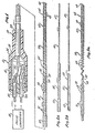
- Fig. 1 is a side elevational view partially in section of a bipolar catheter constructed in accordance with the teachings of this invention coupled to a pulse generator.
- Figs. 2a and 2b are fragmentary side elevational views showing two different forms of wire which can be used for the conductor.
- Figs. 3a, 3b and 3c are side elevational views of three forms of bipolar flexible tip catheters of this invention, respectively. The elastomeric material within the coils is not shown in Figs. 3a and 3b.
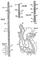
- Fig. 4 is a front elevational view of a unipolar catheter constructed in accordance with the teachings of this invention.
- Fig. 5 is a sectional view through a human heart showing one way in which the catheter of this invention can be used.
- Fig. 1 shows a bipolar catheter 11 electrically coupled to a pulse generator 13. Generally, the catheter 11 comprises a
body 15 and an elongatedinner conductor 17. - The
body 15 includes a backshell 19 having an interior chamber 21, atube 23 received within one end of thebackshell 19, an outer conductor 25 and a flexibleouter cover 27 of a suitable material, such as polytetrafluoroethylene. Theconductors 17 and 25 are suitably coupled within the chamber 21 toleads 29 leading to the pulse generator 13. The chamber 21 may contain a suitable potting compound (not shown) if desired. - In the embodiment illustrated, the outer conductor 25 is in the form of a flat wire, i.e., a wire of nearly rectangular cross section, wound into a series of
contiguous coils 31 which extend from the chamber 21 to a location distally of thecover 27 and axially spacedcoils 33 located distally of the contiguous coils 31. Thecover 27 terminates proximally of the distal end of the conductor 25, and the exposed portion of this conductor forms anelectrode 35. - The
inner conductor 17 is also in the form of an elongated wire having afirst section 37 extending from the chamber 21 axially through thebody 15, atransition section 39 and adistal section 41 with the portion of theinner conductor 17 which is outside of said body being the distal end portion of the inner conductor. As best shown in Fig. 3a, thefirst section 37 is straight and is covered byinsulation 43. Thetransition section 39 comprises a plurality ofcoils 45 which is spaced apart axially, with the axial spacing between adjacent coils progressively reducing as the transition section extends distally. This progressive reduction in spacing is preferred but not essential. Thedistal section 41 comprises a plurality ofcontiguous coils 47 and terminates at adistal end 48 of the catheter 11. These coils could be tightly or loosely wound to further control flexibility. - The
inner conductor 17 may be formed, for example, of a wire 49 (Fig. 2a) or of a wire 51 (Fig. 2b). The wire 49 has acylindrical section 53 of relatively large diameter which can be used to form thefirst section 37 andcylindrical sections transition section 39 and thedistal section 41, respectively. Each of thesections - The wire 51 also has a
cylindrical section 53 from which thefirst section 37 can be formed. However, in lieu of thecylindrical section 55, thewire 53 has aconical section 59 which is of progressively reducing diameter as it extends distally and from which thetransition section 39 can be constructed. Thewire 53 also has acylindrical section 57 from which thedistal section 41 can be constructed. The wires 49 and 51 can be constructed of various suitable materials, such as stainless steel. The wires 49 and 51 can be formed of multiple sections which are suitably joined together as by soldering or welding but, preferably, each of these wires is integral. In this latter event, the wires 49 and 51 can be tapered by electropolishing or centerless grinding. - With the construction described above, the
first section 37 is less flexible than thetransition section 39 and thetransition section 39 is less flexible than thedistal section 41. Also, thefirst section 37 is reinforced by thebody 15. Moreover, the flexibility of thetransition section 39 increases as the transition section extends distally. The relative stiffness of thefirst section 37 is obtained by leaving thefirst section 37 uncoiled and constructing it of larger diameter wire. Thetransition section 39 is more flexible than thefirst section 37 because it is coiled and constructed of smaller diameter wire. The flexibility of thetransition section 39 increases because the axial spacing between thecoils 45 decreases as the transition section extends distally and because theconical sections distal section 41 is more flexible than thetransition section 39 because thecoils 47 are contiguous and because wire of minimum diameter is used to construct it. If the wire 49 is used to construct theinner conductor 17, then the progressive decrease in diameter of theconical section 55 tends to produce progressively greater flexibility in thedistal section 41 as the distal section extends distally. Thedistal section 41 is flexible and resilient all the way to thedistal end 48. - In the embodiment of Figs. 1-3, a
non-conductive elastomer 61 fills the central space within thecoils elastomer 61 helps insulate theconductors 17 and 25 from each other. In the embodiment illustrated, theelastomer 61 terminates, along with thedistal section 41, at thedistal end 48. In this embodiment, the presence of theelastomer 61 does not alter the above-described relative stiffness relationships of thesections elastomer 61 fills the spaces between thecoils 45 and thecoils 33, and in addition, encases thecoils 45 of thetransition section 39 so that only thecoils 47 are exposed to define anelectrode 62. In this embodiment, thedistal section 41 forms theelectrode 62. If theelastomer 61 is eliminated, then it is preferred to encase thecoils 45 of thetransition section 39 in a suitable insulation jacket. - Fig. 5 shows how the catheter can be used by inserting it through the lumen of a guiding
catheter 63. Except for astiffening element 64, the guidingcatheter 63 may be of conventional construction and may be a Swan-Ganz thermodilution catheter which is available from American Edwards Laboratories of Irvine, California. The guidingcatheter 63, which may have multiple lumens extending longitudinally through a catheter body, may be inserted into the heart through a vein using conventional techniques, and following such insertion, aballoon 65 adjacent the distal end of the guiding catheter is lodged in thepulmonary artery 67. As shown in Fig. 5, thecatheter 63 extends through the superior vena cava 66 and is formed into acurve 68 of about 180 degrees as it extends through theright atrium 69 and theright ventricle 71. The guidingcatheter 63 has aport 72 leading from one of its lumens into theright ventricle 71. - In the embodiment illustrated, the stiffening
element 64 is in the form of an elongated, flexible, resilient wire of metal or plastic bonded into the guidingcatheter 63 outside of the lumen with which theport 72 communicates. In the preferred construction illustrated, the stiffeningelement 64 extends from a location in theright atrium 69 proximally of theport 72 continuously to a location in theright ventricle 71 located distally of theport 72. Thus, regions of the guiding catheter on the opposite sides of theports 72 are stiffened, and such stiffening is controlled to cause thecatheter 63 to form the relativelygentle curve 68 in the right heart without kinking as the catheter extends through the right heart to thepulmonary artery 67. - With the guiding
catheter 63 positioned in the right heart as shown in Fig. 5, the catheter 11 can be inserted through a lumen of the guidingcatheter 63 and out theport 72. As the catheter 11 continues its advancing movement, theelectrode 62 contacts awall 73 of the right ventricle and bends over or deflects along the wall due to the resilience of thedistal section 41 all the way to thedistal end 48. This causes theelectrode 62 and thetransition section 39 to resiliently flex and causes the electrode to lie against thewall 73 without penetrating the wall. A circuit can then be completed from theelectrode 62 through theheart wall 73 and body fluids in the heart to theelectrode 35. The flexibility of the catheter 11, and in particular, of theconductors 17 and 25 at, and distally of thedistal electrode 35, maintains thedistal electrode 62 in continuous engagement with thewall 73. Of course, the catheter 11 can be inserted directly through an artery or vein into the heart without using the guidingcatheter 63. The catheter 11 is flexible throughout its length. However, the resilience and flexibility of the catheter are carefully controlled primarily at thesections heart wall 73 and sufficient resilience to maintain contact between thedistal electrode 62 and with the heart wall. - Fig. 3b shows a catheter lla which is identical in all respects not shown or described herein to the catheter 11. Portions of the catheter lla corresponding to portions of the catheter 11 are designated by corresponding reference numerals followed by the letter "a."
- The only difference between the catheters 11 and lla is that the inner conductor 17a of the catheter lla is provided in two parts, i.e., a
straight segment 75 and acoiled segment 77 appropriately joined together as by solder or welding. For this purpose, the distal end of thestraight segment 75 is inserted within a few of the proximal coils of the coiledsegment 77. Thestraight segment 75 defines the first section 37a and thecoiled segment 77 defines thetransition section 39a and the distal section 41a, i.e., the electrode 62a. - Fig. 3c shows a catheter llb which is identical to the catheter 11 in all respects not shown or described herein. Portions of the catheter llb corresponding to portions of the catheter 11 are designated by corresponding reference numerals followed by the letter "b."
- In the catheter llb, the inner conductor 17b comprises a segment 79 and a body 81 of soft, flexible resilient, conductive elastomeric material attached to the distal end of the segment 79. The segment 79 may be a wire or cable. The distal portion of the segment 79 projects beyond the
insulation 43b and terminates in ahead 83 of enlarged cross-sectional area. - The segment 79 between the body 81 and the
electrode 35b is encased in ajacket 85 of soft, flexible, resilient plastic material, which is a nonconductor. This portion of the segment 79 and thejacket 85 form a transition section 39b of a stiffness intermediate the stiffness of the body 81 and the region of the catheter llb proximally of such portion of the segment 79. The segment 79 projects only a short distance into the body 81, and hence, the body 81 is the most flexible part of the inner conductor 17b. Thejacket 85 may extend into the coils defining theelectrode 35b. - The body 81 of elastomeric material may be, for example, molded around the distal tip of the segment 79 so that the
head 83 is embedded within the body 81. This tightly retains the body 81 of elastomeric material against the distal end of thejacket 85. If desired, the body 81 may be adhered or bonded to thejacket 85. The body 81 forms thedistal electrode 62b. The catheters lla and llb may be used in the same manner described above for the catheter 11. - Fig. 4 shows a unipolar catheter llc which is identical in all respects not shown or described herein to the bipolar catheter 11. The only difference between the catheters 11 and llc is that the outer conductor 25 is replaced with a
flexible tube 87 of a suitable biocompatible plastic material. Portions of the catheter llc corresponding to portions of the catheter 11 are designated by corresponding reference numerals followed by the letter "c." As shown schematically in Fig. 4, with the unipolar catheter llc, the circuit is completed through theheart wall 73 to ground, and to accomplish this, the patient is appropriately grounded. - Although exemplary embodiments of the invention have been shown and described, many changes, modifications and substitutions may be made by one having ordinary skill in the art without necessarily departing from the spirit and scope of this invention.
Claims (12)
Priority Applications (1)
| Application Number | Priority Date | Filing Date | Title |
|---|---|---|---|
| EP91116947A EP0467422B1 (en) | 1982-10-14 | 1983-10-10 | Guiding catheter |
Applications Claiming Priority (2)
| Application Number | Priority Date | Filing Date | Title |
|---|---|---|---|
| US43431882A | 1982-10-14 | 1982-10-14 | |
| US434318 | 1982-10-14 |
Related Child Applications (3)
| Application Number | Title | Priority Date | Filing Date |
|---|---|---|---|
| EP87114978.7 Division-Into | 1983-10-10 | ||
| EP91116947.2 Division-Into | 1983-10-10 | ||
| EP87114978 Division | 1987-10-13 |
Publications (4)
| Publication Number | Publication Date |
|---|---|
| EP0109178A2 true EP0109178A2 (en) | 1984-05-23 |
| EP0109178A3 EP0109178A3 (en) | 1984-12-27 |
| EP0109178B1 EP0109178B1 (en) | 1992-05-27 |
| EP0109178B2 EP0109178B2 (en) | 2000-01-26 |
Family
ID=23723743
Family Applications (2)
| Application Number | Title | Priority Date | Filing Date |
|---|---|---|---|
| EP91116947A Expired - Lifetime EP0467422B1 (en) | 1982-10-14 | 1983-10-10 | Guiding catheter |
| EP19830306120 Expired - Lifetime EP0109178B2 (en) | 1982-10-14 | 1983-10-10 | Flexible tip cardiac pacing catheter |
Family Applications Before (1)
| Application Number | Title | Priority Date | Filing Date |
|---|---|---|---|
| EP91116947A Expired - Lifetime EP0467422B1 (en) | 1982-10-14 | 1983-10-10 | Guiding catheter |
Country Status (4)
| Country | Link |
|---|---|
| EP (2) | EP0467422B1 (en) |
| JP (1) | JPS5990566A (en) |
| CA (1) | CA1231392A (en) |
| DE (2) | DE3382568D1 (en) |
Cited By (9)
| Publication number | Priority date | Publication date | Assignee | Title |
|---|---|---|---|---|
| EP0180348A2 (en) * | 1984-10-05 | 1986-05-07 | BAXTER INTERNATIONAL INC. (a Delaware corporation) | Guiding catheter |
| EP0206248A1 (en) * | 1985-06-20 | 1986-12-30 | Medtronic, Inc. | Epicardial electrode arrangements and system for applying electrical energy to a human heart |
| EP0622090A1 (en) * | 1993-04-30 | 1994-11-02 | Medtronic, Inc. | Sintered electrode on a substrate |
| US20110118582A1 (en) * | 2007-05-23 | 2011-05-19 | De La Rama Alan | Magnetically Guided Catheter With Flexible Tip |
| US8974454B2 (en) | 2009-12-31 | 2015-03-10 | St. Jude Medical, Atrial Fibrillation Division, Inc. | Kit for non-invasive electrophysiology procedures and method of its use |
| US8979837B2 (en) | 2007-04-04 | 2015-03-17 | St. Jude Medical, Atrial Fibrillation Division, Inc. | Flexible tip catheter with extended fluid lumen |
| US10039598B2 (en) | 2007-07-03 | 2018-08-07 | St. Jude Medical, Atrial Fibrillation Division, Inc. | Magnetically guided catheter |
| CN109568792A (en) * | 2018-12-26 | 2019-04-05 | 创领心律管理医疗器械(上海)有限公司 | Delivery sheath and pacemaker system |
| US10433903B2 (en) | 2007-04-04 | 2019-10-08 | St. Jude Medical, Atrial Fibrillation Division, Inc. | Irrigated catheter |
Families Citing this family (9)
| Publication number | Priority date | Publication date | Assignee | Title |
|---|---|---|---|---|
| US7771369B2 (en) | 2003-12-05 | 2010-08-10 | Boston Scientific Scimed, Inc. | Guide catheter with removable support |
| DE102004051211A1 (en) | 2004-10-20 | 2006-05-04 | Restate Treuhand & Immobilien Ag | Catheter, in particular for introducing pacemaker or ICD electrodes into a patient's body |
| AU2012351954B2 (en) * | 2011-12-15 | 2016-08-11 | The Board Of Trustees Of The Leland Stanford Junior University | Apparatus and methods for treating pulmonary hypertension |
| CN102908191A (en) | 2012-11-13 | 2013-02-06 | 陈绍良 | Multipolar synchronous pulmonary artery radiofrequency ablation catheter |
| US11241267B2 (en) | 2012-11-13 | 2022-02-08 | Pulnovo Medical (Wuxi) Co., Ltd | Multi-pole synchronous pulmonary artery radiofrequency ablation catheter |
| US9827036B2 (en) | 2012-11-13 | 2017-11-28 | Pulnovo Medical (Wuxi) Co., Ltd. | Multi-pole synchronous pulmonary artery radiofrequency ablation catheter |
| ES2947184T3 (en) | 2016-03-18 | 2023-08-02 | Teleflex Life Sciences Ltd | stimulation guide |
| WO2021086560A1 (en) * | 2019-10-31 | 2021-05-06 | St. Jude Medical, Cardiology Division, Inc. | Catheter including deflectable shaft and methods of assembling same |
| EP4108197A1 (en) | 2021-06-24 | 2022-12-28 | Gradient Denervation Technologies | Systems for treating tissue |
Citations (12)
| Publication number | Priority date | Publication date | Assignee | Title |
|---|---|---|---|---|
| US3416533A (en) * | 1966-05-20 | 1968-12-17 | Gen Electric | Conductive catheter |
| US3596662A (en) * | 1968-09-04 | 1971-08-03 | Medtronic Inc | Electrode for cardiac stimulator |
| US3788329A (en) * | 1972-04-17 | 1974-01-29 | Medtronic Inc | Body implantable lead |
| US3804098A (en) * | 1972-04-17 | 1974-04-16 | Medronic Inc | Body implantable lead |
| US3995623A (en) * | 1974-12-23 | 1976-12-07 | American Hospital Supply Corporation | Multipurpose flow-directed catheter |
| DE2605590A1 (en) * | 1976-02-12 | 1977-08-18 | Heinz Dr Med Praeuer | Pacemaker electrode with flexible electrode catheter - with flexible projecting base for abutment against wall of heart |
| US4161952A (en) * | 1977-11-01 | 1979-07-24 | Mieczyslaw Mirowski | Wound wire catheter cardioverting electrode |
| DE2822829A1 (en) * | 1978-05-24 | 1979-11-29 | Michael S Dipl Ing Lampadius | Bipolar electrode catheter for heart pacer - comprises cardial insertable tip and jacket electrode of vulcanised silicone rubber contg. conductive metal filler |
| WO1981003733A1 (en) * | 1980-06-18 | 1981-12-24 | American Hospital Supply Corp | Pressure-monitoring multiple lumen catheter and method of mounting an electric element therein |
| DE3026936A1 (en) * | 1980-07-16 | 1982-02-04 | Vsesojuznyj kardiologičeskij naučnyj centr Akademii medicinskich Nauk SSSR,, Moskva | Stylet for implanted stimulation electrode - has core wire with attached handle wound into helix at working end |
| EP0057448A1 (en) * | 1981-02-02 | 1982-08-11 | Medtronic, Inc. | Single pass A-V lead |
| WO1983004181A1 (en) * | 1982-05-24 | 1983-12-08 | Mccorkle Charles E Jr | Intravenous channel cardiac electrode and lead assembly and method |
Family Cites Families (3)
| Publication number | Priority date | Publication date | Assignee | Title |
|---|---|---|---|---|
| US3169528A (en) * | 1963-05-24 | 1965-02-16 | Iii Francis S Knox | Coronary sinus sucker |
| US4332259A (en) * | 1979-09-19 | 1982-06-01 | Mccorkle Jr Charles E | Intravenous channel cardiac electrode and lead assembly and method |
| US4289138A (en) * | 1980-06-09 | 1981-09-15 | Medical Testing Systems, Inc. | Electrode assembly for temporary pacing and heart measurements |
-
1983
- 1983-10-06 CA CA000438502A patent/CA1231392A/en not_active Expired
- 1983-10-10 DE DE8383306120T patent/DE3382568D1/en not_active Expired - Lifetime
- 1983-10-10 DE DE19833382818 patent/DE3382818T2/en not_active Expired - Lifetime
- 1983-10-10 EP EP91116947A patent/EP0467422B1/en not_active Expired - Lifetime
- 1983-10-10 EP EP19830306120 patent/EP0109178B2/en not_active Expired - Lifetime
- 1983-10-14 JP JP19107383A patent/JPS5990566A/en active Granted
Patent Citations (12)
| Publication number | Priority date | Publication date | Assignee | Title |
|---|---|---|---|---|
| US3416533A (en) * | 1966-05-20 | 1968-12-17 | Gen Electric | Conductive catheter |
| US3596662A (en) * | 1968-09-04 | 1971-08-03 | Medtronic Inc | Electrode for cardiac stimulator |
| US3788329A (en) * | 1972-04-17 | 1974-01-29 | Medtronic Inc | Body implantable lead |
| US3804098A (en) * | 1972-04-17 | 1974-04-16 | Medronic Inc | Body implantable lead |
| US3995623A (en) * | 1974-12-23 | 1976-12-07 | American Hospital Supply Corporation | Multipurpose flow-directed catheter |
| DE2605590A1 (en) * | 1976-02-12 | 1977-08-18 | Heinz Dr Med Praeuer | Pacemaker electrode with flexible electrode catheter - with flexible projecting base for abutment against wall of heart |
| US4161952A (en) * | 1977-11-01 | 1979-07-24 | Mieczyslaw Mirowski | Wound wire catheter cardioverting electrode |
| DE2822829A1 (en) * | 1978-05-24 | 1979-11-29 | Michael S Dipl Ing Lampadius | Bipolar electrode catheter for heart pacer - comprises cardial insertable tip and jacket electrode of vulcanised silicone rubber contg. conductive metal filler |
| WO1981003733A1 (en) * | 1980-06-18 | 1981-12-24 | American Hospital Supply Corp | Pressure-monitoring multiple lumen catheter and method of mounting an electric element therein |
| DE3026936A1 (en) * | 1980-07-16 | 1982-02-04 | Vsesojuznyj kardiologičeskij naučnyj centr Akademii medicinskich Nauk SSSR,, Moskva | Stylet for implanted stimulation electrode - has core wire with attached handle wound into helix at working end |
| EP0057448A1 (en) * | 1981-02-02 | 1982-08-11 | Medtronic, Inc. | Single pass A-V lead |
| WO1983004181A1 (en) * | 1982-05-24 | 1983-12-08 | Mccorkle Charles E Jr | Intravenous channel cardiac electrode and lead assembly and method |
Cited By (18)
| Publication number | Priority date | Publication date | Assignee | Title |
|---|---|---|---|---|
| EP0180348A2 (en) * | 1984-10-05 | 1986-05-07 | BAXTER INTERNATIONAL INC. (a Delaware corporation) | Guiding catheter |
| EP0180348B1 (en) * | 1984-10-05 | 1992-05-06 | BAXTER INTERNATIONAL INC. (a Delaware corporation) | Guiding catheter |
| EP0206248A1 (en) * | 1985-06-20 | 1986-12-30 | Medtronic, Inc. | Epicardial electrode arrangements and system for applying electrical energy to a human heart |
| EP0622090A1 (en) * | 1993-04-30 | 1994-11-02 | Medtronic, Inc. | Sintered electrode on a substrate |
| AU673038B2 (en) * | 1993-04-30 | 1996-10-24 | Medtronic, Inc. | Substrate for a sintered electrode |
| US8979837B2 (en) | 2007-04-04 | 2015-03-17 | St. Jude Medical, Atrial Fibrillation Division, Inc. | Flexible tip catheter with extended fluid lumen |
| US11559658B2 (en) | 2007-04-04 | 2023-01-24 | St. Jude Medical, Atrial Fibrillation Division, Inc. | Flexible tip catheter with extended fluid lumen |
| US10433903B2 (en) | 2007-04-04 | 2019-10-08 | St. Jude Medical, Atrial Fibrillation Division, Inc. | Irrigated catheter |
| US9724492B2 (en) | 2007-04-04 | 2017-08-08 | St. Jude Medical, Atrial Fibrillation Division, Inc. | Flexible tip catheter with extended fluid lumen |
| US10576244B2 (en) | 2007-04-04 | 2020-03-03 | St. Jude Medical, Atrial Fibrillation Division, Inc. | Flexible tip catheter with extended fluid lumen |
| US8790341B2 (en) | 2007-05-23 | 2014-07-29 | St. Jude Medical, Atrial Fibrillation Division, Inc. | Ablation catheter with flexible tip |
| US8827910B2 (en) * | 2007-05-23 | 2014-09-09 | St. Jude Medical, Atrial Fibrillation Divsion, Inc. | Magnetically guided catheter with flexible tip |
| US9510903B2 (en) | 2007-05-23 | 2016-12-06 | St. Jude Medical, Atrial Fibrillation Division, Inc. | Irrigated flexible ablation catheter |
| US20110118582A1 (en) * | 2007-05-23 | 2011-05-19 | De La Rama Alan | Magnetically Guided Catheter With Flexible Tip |
| US10039598B2 (en) | 2007-07-03 | 2018-08-07 | St. Jude Medical, Atrial Fibrillation Division, Inc. | Magnetically guided catheter |
| US8974454B2 (en) | 2009-12-31 | 2015-03-10 | St. Jude Medical, Atrial Fibrillation Division, Inc. | Kit for non-invasive electrophysiology procedures and method of its use |
| CN109568792A (en) * | 2018-12-26 | 2019-04-05 | 创领心律管理医疗器械(上海)有限公司 | Delivery sheath and pacemaker system |
| CN109568792B (en) * | 2018-12-26 | 2023-04-18 | 创领心律管理医疗器械(上海)有限公司 | Delivery sheath and pacemaker system |
Also Published As
| Publication number | Publication date |
|---|---|
| DE3382568D1 (en) | 1992-07-02 |
| JPS5990566A (en) | 1984-05-25 |
| EP0109178B2 (en) | 2000-01-26 |
| EP0467422B1 (en) | 1997-12-17 |
| DE3382818T2 (en) | 1998-07-16 |
| EP0109178B1 (en) | 1992-05-27 |
| DE3382818D1 (en) | 1998-01-29 |
| JPH0415701B2 (en) | 1992-03-18 |
| EP0109178A3 (en) | 1984-12-27 |
| EP0467422A3 (en) | 1992-04-29 |
| EP0467422A2 (en) | 1992-01-22 |
| CA1231392A (en) | 1988-01-12 |
Similar Documents
| Publication | Publication Date | Title |
|---|---|---|
| US4759378A (en) | Flexible tip cardiac pacing catheter | |
| US4651751A (en) | Guiding catheter and method of use | |
| US5133365A (en) | Implantable tapered spiral endocardial lead for use in internal defibrillation | |
| EP0109178B2 (en) | Flexible tip cardiac pacing catheter | |
| US5016808A (en) | Implantable tapered spiral endocardial lead for use in internal defibrillation | |
| US7389148B1 (en) | Electrode design for defibrillation and/or sensing capabilities | |
| US5925073A (en) | Intravenous cardiac lead with wave shaped fixation segment | |
| US6493591B1 (en) | Implantable active fixation lead with guidewire tip | |
| EP0428279B1 (en) | Braid electrode leads and catheters for using the same | |
| US4135518A (en) | Body implantable lead and electrode | |
| US5800497A (en) | Medical electrical lead with temporarily stiff portion | |
| US6370434B1 (en) | Cardiac lead and method for lead implantation | |
| US8509916B2 (en) | Bilumen guide catheters for accessing cardiac sites | |
| EP0954240B1 (en) | Side access "over the wire" pacing lead | |
| US4791939A (en) | Stylet for use with an implantable pacing lead | |
| US4721118A (en) | Pervenous electrical pacing lead with foldable fins | |
| US5466253A (en) | Crush resistant multi-conductor lead body | |
| US6871085B2 (en) | Cardiac vein lead and guide catheter | |
| US7229450B1 (en) | Kink resistant introducer with mapping capabilities | |
| US6580949B1 (en) | Implantable electrode lead | |
| EP0601338A1 (en) | Electrode system for a defibrillator | |
| US5358517A (en) | Electrical medical lead with textured stylet guide | |
| US4454888A (en) | Cardiac pacing lead with curve retainer | |
| US6973351B2 (en) | Leads using composite materials for conductors and stylet insertion for improved handling characteristics in lead implantation performance | |
| EP0715865A2 (en) | Steerable stylet assembly |
Legal Events
| Date | Code | Title | Description |
|---|---|---|---|
| PUAI | Public reference made under article 153(3) epc to a published international application that has entered the european phase |
Free format text: ORIGINAL CODE: 0009012 |
|
| AK | Designated contracting states |
Kind code of ref document: A2 Designated state(s): BE DE FR GB |
|
| PUAL | Search report despatched |
Free format text: ORIGINAL CODE: 0009013 |
|
| AK | Designated contracting states |
Designated state(s): BE DE FR GB |
|
| 17P | Request for examination filed |
Effective date: 19850501 |
|
| 17Q | First examination report despatched |
Effective date: 19870219 |
|
| RAP1 | Party data changed (applicant data changed or rights of an application transferred) |
Owner name: BAXTER TRAVENOL LABORATORIES, INC. |
|
| 18D | Application deemed to be withdrawn |
Effective date: 19870702 |
|
| 18RA | Request filed for re-establishment of rights before grant |
Effective date: 19880331 |
|
| 18RR | Decision to grant the request for re-establishment of rights before grant |
Free format text: 900817 ANGENOMMEN |
|
| REG | Reference to a national code |
Ref country code: DE Ref legal event code: 8570 |
|
| RAP1 | Party data changed (applicant data changed or rights of an application transferred) |
Owner name: BAXTER INTERNATIONAL INC. |
|
| D18D | Application deemed to be withdrawn (deleted) | ||
| GRAA | (expected) grant |
Free format text: ORIGINAL CODE: 0009210 |
|
| RTI1 | Title (correction) | ||
| AK | Designated contracting states |
Kind code of ref document: B1 Designated state(s): BE DE FR GB |
|
| XX | Miscellaneous (additional remarks) |
Free format text: TEILANMELDUNG 91116947.2 EINGEREICHT AM 10/10/83. |
|
| REF | Corresponds to: |
Ref document number: 3382568 Country of ref document: DE Date of ref document: 19920702 |
|
| ET | Fr: translation filed | ||
| PLBI | Opposition filed |
Free format text: ORIGINAL CODE: 0009260 |
|
| 26 | Opposition filed |
Opponent name: BIOTRONIK MESS- UND THERAPIEGERAETE GMBH & CO ING Effective date: 19930227 |
|
| APAC | Appeal dossier modified |
Free format text: ORIGINAL CODE: EPIDOS NOAPO |
|
| PLAW | Interlocutory decision in opposition |
Free format text: ORIGINAL CODE: EPIDOS IDOP |
|
| RIC2 | Information provided on ipc code assigned after grant |
Free format text: 6A 61N 1/05 A, 6A 61M 25/01 B |
|
| PUAH | Patent maintained in amended form |
Free format text: ORIGINAL CODE: 0009272 |
|
| STAA | Information on the status of an ep patent application or granted ep patent |
Free format text: STATUS: PATENT MAINTAINED AS AMENDED |
|
| 27A | Patent maintained in amended form |
Effective date: 20000126 |
|
| AK | Designated contracting states |
Kind code of ref document: B2 Designated state(s): BE DE FR GB |
|
| XX | Miscellaneous (additional remarks) |
Free format text: TEILANMELDUNG 91116947.2 EINGEREICHT AM 10/10/83. |
|
| ET3 | Fr: translation filed ** decision concerning opposition | ||
| REG | Reference to a national code |
Ref country code: GB Ref legal event code: IF02 |
|
| PGFP | Annual fee paid to national office [announced via postgrant information from national office to epo] |
Ref country code: FR Payment date: 20020918 Year of fee payment: 20 |
|
| PGFP | Annual fee paid to national office [announced via postgrant information from national office to epo] |
Ref country code: GB Payment date: 20021002 Year of fee payment: 20 |
|
| PGFP | Annual fee paid to national office [announced via postgrant information from national office to epo] |
Ref country code: BE Payment date: 20021023 Year of fee payment: 20 |
|
| PGFP | Annual fee paid to national office [announced via postgrant information from national office to epo] |
Ref country code: DE Payment date: 20021031 Year of fee payment: 20 |
|
| PG25 | Lapsed in a contracting state [announced via postgrant information from national office to epo] |
Ref country code: GB Free format text: LAPSE BECAUSE OF EXPIRATION OF PROTECTION Effective date: 20031009 |
|
| REG | Reference to a national code |
Ref country code: GB Ref legal event code: PE20 |
|
| BE20 | Be: patent expired |
Owner name: *BAXTER INTERNATIONAL INC. Effective date: 20031010 |
|
| APAH | Appeal reference modified |
Free format text: ORIGINAL CODE: EPIDOSCREFNO |