EP0109283A1 - Heat and pressure fuser apparatus - Google Patents
Heat and pressure fuser apparatus Download PDFInfo
- Publication number
- EP0109283A1 EP0109283A1 EP83306907A EP83306907A EP0109283A1 EP 0109283 A1 EP0109283 A1 EP 0109283A1 EP 83306907 A EP83306907 A EP 83306907A EP 83306907 A EP83306907 A EP 83306907A EP 0109283 A1 EP0109283 A1 EP 0109283A1
- Authority
- EP
- European Patent Office
- Prior art keywords
- fuser
- abhesive
- abhesive material
- substrate
- fuser member
- Prior art date
- Legal status (The legal status is an assumption and is not a legal conclusion. Google has not performed a legal analysis and makes no representation as to the accuracy of the status listed.)
- Granted
Links
- 239000000463 material Substances 0.000 claims abstract description 37
- 239000000758 substrate Substances 0.000 claims abstract description 19
- 230000015572 biosynthetic process Effects 0.000 claims abstract description 6
- 239000007787 solid Substances 0.000 claims abstract description 4
- 229920001343 polytetrafluoroethylene Polymers 0.000 claims description 8
- 239000004810 polytetrafluoroethylene Substances 0.000 claims description 8
- 238000010438 heat treatment Methods 0.000 claims description 7
- 239000002184 metal Substances 0.000 claims description 7
- 239000004812 Fluorinated ethylene propylene Substances 0.000 claims description 6
- 229920001577 copolymer Polymers 0.000 claims description 6
- 229920009441 perflouroethylene propylene Polymers 0.000 claims description 6
- BFKJFAAPBSQJPD-UHFFFAOYSA-N tetrafluoroethene Chemical group FC(F)=C(F)F BFKJFAAPBSQJPD-UHFFFAOYSA-N 0.000 claims description 5
- HQQADJVZYDDRJT-UHFFFAOYSA-N ethene;prop-1-ene Chemical group C=C.CC=C HQQADJVZYDDRJT-UHFFFAOYSA-N 0.000 claims description 4
- -1 polytetrafluoroethylene Polymers 0.000 claims description 4
- 229920001774 Perfluoroether Polymers 0.000 claims description 3
- 229920002313 fluoropolymer Polymers 0.000 claims description 3
- 229920001897 terpolymer Polymers 0.000 claims description 2
- 230000003028 elevating effect Effects 0.000 claims 3
- 229920002545 silicone oil Polymers 0.000 abstract description 9
- 239000011248 coating agent Substances 0.000 abstract description 8
- 238000000576 coating method Methods 0.000 abstract description 8
- 239000003795 chemical substances by application Substances 0.000 abstract description 6
- 230000000181 anti-adherent effect Effects 0.000 abstract 1
- 230000015556 catabolic process Effects 0.000 abstract 1
- 238000006731 degradation reaction Methods 0.000 abstract 1
- 239000000843 powder Substances 0.000 description 20
- 238000012546 transfer Methods 0.000 description 8
- 239000012530 fluid Substances 0.000 description 6
- 238000000034 method Methods 0.000 description 5
- 229920005989 resin Polymers 0.000 description 5
- 239000011347 resin Substances 0.000 description 5
- 229920002449 FKM Polymers 0.000 description 3
- 238000011161 development Methods 0.000 description 3
- 239000002245 particle Substances 0.000 description 3
- 229920002379 silicone rubber Polymers 0.000 description 3
- BQCIDUSAKPWEOX-UHFFFAOYSA-N 1,1-Difluoroethene Chemical compound FC(F)=C BQCIDUSAKPWEOX-UHFFFAOYSA-N 0.000 description 2
- 239000008187 granular material Substances 0.000 description 2
- HCDGVLDPFQMKDK-UHFFFAOYSA-N hexafluoropropylene Chemical group FC(F)=C(F)C(F)(F)F HCDGVLDPFQMKDK-UHFFFAOYSA-N 0.000 description 2
- 239000007788 liquid Substances 0.000 description 2
- 238000012986 modification Methods 0.000 description 2
- 230000004048 modification Effects 0.000 description 2
- ORQBXQOJMQIAOY-UHFFFAOYSA-N nobelium Chemical compound [No] ORQBXQOJMQIAOY-UHFFFAOYSA-N 0.000 description 2
- 108091008695 photoreceptors Proteins 0.000 description 2
- 238000012545 processing Methods 0.000 description 2
- 241000149947 Coronarchaica corona Species 0.000 description 1
- 239000000853 adhesive Substances 0.000 description 1
- 230000001070 adhesive effect Effects 0.000 description 1
- 238000013461 design Methods 0.000 description 1
- 150000004985 diamines Chemical class 0.000 description 1
- 235000013870 dimethyl polysiloxane Nutrition 0.000 description 1
- 239000004205 dimethyl polysiloxane Substances 0.000 description 1
- 239000013536 elastomeric material Substances 0.000 description 1
- 239000000945 filler Substances 0.000 description 1
- 229920001973 fluoroelastomer Polymers 0.000 description 1
- 150000002500 ions Chemical class 0.000 description 1
- 239000000203 mixture Substances 0.000 description 1
- 238000006386 neutralization reaction Methods 0.000 description 1
- 229920000620 organic polymer Polymers 0.000 description 1
- 229920005668 polycarbonate resin Polymers 0.000 description 1
- 239000004431 polycarbonate resin Substances 0.000 description 1
- 229920000642 polymer Polymers 0.000 description 1
- 229920001296 polysiloxane Polymers 0.000 description 1
- 239000004945 silicone rubber Substances 0.000 description 1
- 239000007921 spray Substances 0.000 description 1
- 229920005992 thermoplastic resin Polymers 0.000 description 1
Images

Classifications
-
- G—PHYSICS
- G03—PHOTOGRAPHY; CINEMATOGRAPHY; ANALOGOUS TECHNIQUES USING WAVES OTHER THAN OPTICAL WAVES; ELECTROGRAPHY; HOLOGRAPHY
- G03G—ELECTROGRAPHY; ELECTROPHOTOGRAPHY; MAGNETOGRAPHY
- G03G15/00—Apparatus for electrographic processes using a charge pattern
- G03G15/20—Apparatus for electrographic processes using a charge pattern for fixing, e.g. by using heat
- G03G15/2003—Apparatus for electrographic processes using a charge pattern for fixing, e.g. by using heat using heat
- G03G15/2014—Apparatus for electrographic processes using a charge pattern for fixing, e.g. by using heat using heat using contact heat
- G03G15/2053—Structural details of heat elements, e.g. structure of roller or belt, eddy current, induction heating
Definitions
- This invention relates, in general, to apparatus for fixing toner images to a substrate and, in particular, to a heat and pressure fuser which can be used without the application of release agent material.
- the present invention is particularly useful in the field of xerography where images are electrostatically formed upon a member and developed with resinous powders known as toners, and thereafter fused or fixed onto sheets of paper or other substrates to which the powder images have been transferred.
- the resin-based powders or toners are generally heat and/or pressure softenable, such as those provided by toners which contain thermoplastic resins and have been used conventionally in a variety of commercially known methods.
- silicone oils are generally well adapted for this purpose.
- silicone oils are generally well adapted for this purpose.
- polydimethyl-siloxane fluids well known for this purpose but certain functional polyorganosiloxane release agents have also been described for this purpose.
- fluids of low viscosity for example, 100-200 centistokes as well as fluids of relatively high viscosity, for example, 12,000 centistokes to 60,000 centistokes and higher.
- release agent management (RAM) systems, the most common of which comprises a wick structure supported in physical contact with the fuser roll. It has long been recognized that the inclusion of a release agent management system as a necessary part of a fuser design represents a significant percentage of the cost of fusing toner images. Not only is the cost of a RAM system undesirable but use of oily fluids per se is undesirable because they contaminate other parts of the machine in which they are used.
- the fuser apparatus of the present invention comprises a heated roller comprising an abhesive (i.e. low affinity for softened toner materials or the like) material for the outer surface thereof which is adapted to deform when pressure engaged with a rigid backup roller, the degree of deformation being of a magnitude such that it contributes to the formation of a nip between the fuser and backup rollers through which the copy substrates carrying the toner images thereon are moved with the toner images contacting the heated roller.
- abhesive i.e. low affinity for softened toner materials or the like
- abhesive material Another important aspect of the abhesive material is that it possesses the capability of continued use in the fuser environment without the loss of its abhesive property.
- suitable abhesive materials are fluorinated polymers and copolymers such as polytetrafluoroethylene (PTFE), fluorinated ethylene propylene (FEP) and perfluoroalkoxy/tetrafluoroethylene (PFA).
- the machine utilizes a photoconductive belt 10 which consists of an electrically conductive substrate 11, a charge generator layer 12, comprising photoconductive particles randomly dispersed in an electrically insulating organic resin, and a charge transport layer 14, comprising a transparent electrically inactive polycarbonate resin having dissolved therein one or more diamines.
- a photoreceptor of this type is disclosed in U.S. Patent No. 4,265,990.
- Belt 10 moves in the direction of arrow 16 to advance successive portions thereof sequentially through the various processing stations disposed about the path of movement thereof.
- Belt 10 is entrained about stripping roller 18, tension roller 20, and drive roller 22.
- Drive roller 22 is mounted rotatably and in engagement with belt 10.
- Motor 24 rotates roller 22 to advance belt 10 in the direction of arrow 16.
- Roller 22 is coupled to motor 24 by suitable means such as belt drive.
- Belt 10 is maintained in tension by a pair of springs (not shown) resiliently urging tension roller 20 against belt 10 with the desired spring force. Both stripping roller 18 and tension roller 20 are rotatably mounted. These rollers are idlers which rotate freely as belt 10 moves in the direction of arrow 16.
- a corona device At charging station A, a corona device, indicated generally by the reference numeral 25, charges the belt 10 to a relatively high, substantially uniform negative potential.
- a suitable corona generating device for negatively charging the photoconductive belt 10 comprises a conductive shield 26 and a dicorotron electrode comprising an elongated bare wire 27 and a relatively thick electrically insulating layer 28 having a thickness which precludes a net d.c. corona current when an a.c. voltage is applied to the corona wire and when the shield and the photoconductive surface are at the same potential. Stated differently, in the absence of an external field supplied by either a bias applied to the shield or a charge on the photoreceptor, there is substantially no net d.c. current flow.
- the charged portion of photoconductive belt is advanced through exposure station B.
- an original document 30 is positioned facedown upon transparent platen 32.
- Lamps 34 flash light rays onto original document 30.
- the light rays reflected from original document 30 form light images which are transmitted through lens 36.
- the light images are projected onto the charged portion of the photoconductive belt to dissipate the charge thereon selectively.
- This records an electrostatic latent image on the belt which corresponds to the informational area contained within original document 30.
- the exposure station B could contain an electrographic recording device for placing electrostatic images on the belt 10, in which case the corona device 25 would be unnecessary.
- belt 10 advances the electrostatic latent image to development station C.
- a magnetic brush developer roller 38 advances a developer mix (i.e. toner and carrier granules) into contact with the electrostatic latent image.
- the latent image attracts the toner particles from the carrier granules thereby forming toner powder images on the photoconductive belt.
- Belt 10 then advances the toner powder image to transfer station D.
- a sheet of support material 40 is moved into contact with the toner powder images.
- the sheet of support material is advanced to transfer station D by a sheet-feeding apparatus 42.
- sheet-feeding apparatus 42 includes a feed roll 44 contacting the upper sheet of stack 46. Feed roll 44 rotates so as to advance the uppermost sheet from stack 46 into chute 48. Chute 48 directs the advancing sheet of support material into contact with the belt 10 in timed sequence so that the toner powder image developed thereon contacts the advancing sheet of support material at transfer station D.
- Transfer station D includes a corona-generating device 50 which sprays negative ions onto the backside of sheet 40 so that the toner powder images, which comprise positive toner particles, are attracted from photoconductive belt 10 to sheet 40.
- a corona-generating device 50 which sprays negative ions onto the backside of sheet 40 so that the toner powder images, which comprise positive toner particles, are attracted from photoconductive belt 10 to sheet 40.
- approximately 50 microamperes of negative current flow to the copy sheet is effected by the application of a suitable corona generating voltage and proper bias.
- the image sheet moves past a detack corona-generating device 51 positioned at a detack station E.
- a detack station At the detack station the charges placed on the reverse of the copy sheet during transfer are partially neutralized. The partial neutralization of the charges thereby reduces the bonding forces holding the sheet to the belt 10, thus enabling the sheet to be stripped as the belt moves around the rather sharp bend in the belt provided by the roller 18.
- the sheet After detack, the sheet continues to move in the direction of arrow 52 onto a conveyor (not shown) which advances the sheet to fusing station F.
- Fusing station F includes a fuser assembly, indicated generally by the reference numeral 54, which permanently affixes the transferred toner powder images to sheet 40.
- fuser assembly 54 includes a heated fuser member in the form of a roller 56 adapted to be pressure engaged with a backup roller 58.
- Sheet 40 passes between fuser roller 56 and backup roller 58 with the toner powder images contacting fuser roller 56. In this manner, the toner powder image is permanently affixed to sheet 40.
- chute 60 guides the advancing sheet 40 to catch tray 62 for removal from the printing machine by the operator.
- the heated roller 56 comprises a rigid metal core 64 to which there is adhered a relatively thin (e.g. approx. 0.2mm) resilient layer 66 of Viton or any other suitable elastomeric material such as silicone rubber.
- Viton is a trademark of E. I. DuPont de Nemours and Co. for a series of fluoroelastomers based on the copolymer of vinylidene fluoride and hexafluoropropylene and terpolymers of vinylidene fluoride, hexafluoropropylene and tetrafluoroethylene.
- An outer covering 68 on the layer 66 is of solid abhesive (i.e.
- Typical adhesive materials comprise fluorinated polymers and copolymers such as polytetrafluoroethylene (PTFE), fluorinated ethylene propylene (FEP) and perfluoroalkoxy/tetrafluoroethylene (PFA).
- PTFE polytetrafluoroethylene
- FEP fluorinated ethylene propylene
- PFA perfluoroalkoxy/tetrafluoroethylene
- the roller 56 is internally heated by means of a conventional heat source 74.
- the heat source 74 is controlled in a conventional manner such that surface temperature of the roll runs on the order of 132 to 166°C. These temperatures are adequate to fuse conventional heat-settable toners when the pressure exerted in the nip is about 5.5 M Nm 2 .
- the roller 76 comprises a rigid core 78 having a heat source 80 supported internally thereof and a relatively thick (e.g. 0.50 mm) outer coating 82 of abhesive material. Because the coating 82 is relatively thick, it is capable of being indented or deformed to form the nip 70. Again, as in the case of the embodiment of Figure 2, no silicone oil is necessary, because of the abhesive nature of the material and the thickness thereof which allows the material to contribute to the formation of the nip.
- the '351 type of fuser roller comprises a PTFE coating adhered to a rigid core, the thickness of the coating being only 0.025 - 0.075 mm thick. Thus, such a coating is not sufficiently deformable to allow use of the fuser roll without the silicone.
- FIG. 4 Another embodiment of the fuser apparatus of the present invention as illustrated in Figure 4 comprises heated fuser member 86 fabricated from a relatively thin metal shell 88 overcoated with a relatively thin layer 90 of abhesive material as discussed above.
- the shell thickness is of the order of 0.25 mm and the thickness of the layer 90 is in the range of 0.025 -0.075 mm.
- the thickness of the shell together with the layer 90 is small enough for this structure to be relatively flexible, so that it can conform to the radius of the rigid backup roll thereby to form a nip 92.
- the fuser member is internally heated by means of heat source 74.
- a pair of positioning rolls 94 and 95 cooperate with the shell 88 to guide the fuser member into proper nip-forming contact with the backup roller 72.
- a relatively thick (e.g. 7.5 mm) deformable layer 104 of Viton is adhered to the core and the layer 104 is covered with a relatively-thin (0.025 - 0.050 mm) abhesive material 105 of the type mentioned hereinabove.
- the pressure roll 106 is rigid so as to cause the layer 104 to deform, thereby forming the nip 108 between the two rolls.
- An external source of heat 110 is provided for maintaining the surface temperature of the fuser roll at the fusing temperature during the run mode of operation, the heating element 102 providing the energy to maintain the fuser roll at a predetermined standby temperature.
- a suitable control (not shown) can be employed first to energize the internal heating element during standby and then to actuate the external heating element with simultaneous de-energization of the heating element. Such a control is disclosed in U.S. 4,197,445.
- the present invention discloses a heat and pressure fuser apparatus which does not require the use of silicone oil.
- the fuser member that contacts the toner images on the carrier substrate comprises an abhesive material as the outer coating thereof that will function as such for an extended period of time.
- the fuser member is fabricated such that the abhesive material contributes to the formation of the nip between it and a backup roll.
Abstract
Description
- This invention relates, in general, to apparatus for fixing toner images to a substrate and, in particular, to a heat and pressure fuser which can be used without the application of release agent material.
- The present invention is particularly useful in the field of xerography where images are electrostatically formed upon a member and developed with resinous powders known as toners, and thereafter fused or fixed onto sheets of paper or other substrates to which the powder images have been transferred. The resin-based powders or toners are generally heat and/or pressure softenable, such as those provided by toners which contain thermoplastic resins and have been used conventionally in a variety of commercially known methods.
- In order to fuse images formed of the resinous powders or toners, it is necessary to heat the powder, to submit the powder to pressure or to use a combination of heat and pressure to fix or fuse the resinous powders or toners to a particular substrate. Temperature and/or pressure ranges will vary depending upon the softening range of the particular resin used in the toner. When heat is used in conjunction with pressure to fuse the images to a substrate, it is generally necessary to heat the toner powder using fuser rolls heated to a prenip temperature in excess of about 180°C. or higher. Temperatures as high as 193°C. or even higher are not uncommon in commercially known methods and devices. Corresponding nip pressure is on the order of 100-200 PSI, (690-1380 kNm -2).
- It has long been recognized that one of the fastest and most positive methods of applying heat for fusing the powder image is by direct contact of the resin-based powder with a hot surface, such as a heated roll while pressure is being applied to the substrate to which the powder image is to be fused or fixed. In most instances, the powder image is tackified by the heat and/or pressure, so that part of the image carried by the support material will stick to the surface of the plate or roll so that as the next sheet is advanced to the heated surface, the tackified image partially removed from the first sheet, will partly transfer to the next sheet and at the same time part of the tackified image from said next sheet would adhere to the heated surface. This process is commonly referred to in the art as "offset," a term well known in the art.
- The offset of toner onto the heated surface lead to the development of improved methods and apparatus for fusing the toner image. These improvements comprised fusing toner images by forwarding the sheet or web of substrate material bearing the image between two rolls at least one of which was heated, the rolls contacting the image being provided with a thin (e.g. 0.0025-0.075 mm) coating of tetrafluoroethylene resin and a silicone oil film to prevent toner offset. The outer surfaces of such rolls have also been fabricated of fluorinated ethylene propylene or silicone elastomers coated with silicone oil as well as silicone elastomers containing low surface energy fillers such as fluorinated organic polymers, and the like. The tendency of these rolls to pick up the toner generally requires some type of release fluid to be continuously applied to the surface of the roll to prevent such offset, and commonly known silicone oils are generally well adapted for this purpose. Not only are the polydimethyl-siloxane fluids well known for this purpose but certain functional polyorganosiloxane release agents have also been described for this purpose. It is also well known to utilize fluids of low viscosity, for example, 100-200 centistokes as well as fluids of relatively high viscosity, for example, 12,000 centistokes to 60,000 centistokes and higher.
- These fluids are applied to the surface of the heated roll by various devices known as release agent management (RAM) systems, the most common of which comprises a wick structure supported in physical contact with the fuser roll. It has long been recognized that the inclusion of a release agent management system as a necessary part of a fuser design represents a significant percentage of the cost of fusing toner images. Not only is the cost of a RAM system undesirable but use of oily fluids per se is undesirable because they contaminate other parts of the machine in which they are used.
- In accordance with the present invention there is provided a heat and pressure fuser apparatus for fixing toner images to copy substrates. In particular, a fuser apparatus is disclosed which does not require the application of release agent material in order to prevent toner offset. To this end, the fuser apparatus of the present invention comprises a heated roller comprising an abhesive (i.e. low affinity for softened toner materials or the like) material for the outer surface thereof which is adapted to deform when pressure engaged with a rigid backup roller, the degree of deformation being of a magnitude such that it contributes to the formation of a nip between the fuser and backup rollers through which the copy substrates carrying the toner images thereon are moved with the toner images contacting the heated roller. Another important aspect of the abhesive material is that it possesses the capability of continued use in the fuser environment without the loss of its abhesive property. Examples of suitable abhesive materials are fluorinated polymers and copolymers such as polytetrafluoroethylene (PTFE), fluorinated ethylene propylene (FEP) and perfluoroalkoxy/tetrafluoroethylene (PFA).
- For a general understanding of the features of the present invention, a description thereof will be made with reference to the accompanying drawings wherein:
- Figure 1 schematically depicts the various components of an illustrative electrophotographic machine incorporating the invention;
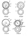
- Figure 2 is a schematic representation of a fuser apparatus incorporating one embodiment of the invention;
- Figure 3 is a schematic representation of a fuser apparatus incorporating a modified embodiment of the invention;
- Figure 4 is a further modification of the invention, and
- Figure 5 is yet a further modification of the invention.
- Inasmuch as the art of electrophotography is well known, the various processing stations employed in the printing machine illustrated in the Figure 1 will be described only briefly.
- As shown in Figure 1, the machine utilizes a
photoconductive belt 10 which consists of an electrically conductive substrate 11, acharge generator layer 12, comprising photoconductive particles randomly dispersed in an electrically insulating organic resin, and acharge transport layer 14, comprising a transparent electrically inactive polycarbonate resin having dissolved therein one or more diamines. A photoreceptor of this type is disclosed in U.S. Patent No. 4,265,990.Belt 10 moves in the direction ofarrow 16 to advance successive portions thereof sequentially through the various processing stations disposed about the path of movement thereof.Belt 10 is entrained aboutstripping roller 18,tension roller 20, and drive roller 22. Drive roller 22 is mounted rotatably and in engagement withbelt 10.Motor 24 rotates roller 22 to advancebelt 10 in the direction ofarrow 16. Roller 22 is coupled tomotor 24 by suitable means such as belt drive. -
Belt 10 is maintained in tension by a pair of springs (not shown) resiliently urgingtension roller 20 againstbelt 10 with the desired spring force. Bothstripping roller 18 andtension roller 20 are rotatably mounted. These rollers are idlers which rotate freely asbelt 10 moves in the direction ofarrow 16. - With continued reference to Figure 1, initially a portion of
belt 10 passes through charging station A. At charging station A, a corona device, indicated generally by the reference numeral 25, charges thebelt 10 to a relatively high, substantially uniform negative potential. A suitable corona generating device for negatively charging thephotoconductive belt 10 comprises aconductive shield 26 and a dicorotron electrode comprising an elongated bare wire 27 and a relatively thick electrically insulating layer 28 having a thickness which precludes a net d.c. corona current when an a.c. voltage is applied to the corona wire and when the shield and the photoconductive surface are at the same potential. Stated differently, in the absence of an external field supplied by either a bias applied to the shield or a charge on the photoreceptor, there is substantially no net d.c. current flow. - Next, the charged portion of photoconductive belt is advanced through exposure station B. At exposure station B, an
original document 30 is positioned facedown upontransparent platen 32.Lamps 34 flash light rays ontooriginal document 30. The light rays reflected fromoriginal document 30 form light images which are transmitted throughlens 36. The light images are projected onto the charged portion of the photoconductive belt to dissipate the charge thereon selectively. This records an electrostatic latent image on the belt which corresponds to the informational area contained withinoriginal document 30. Alternatively, the exposure station B could contain an electrographic recording device for placing electrostatic images on thebelt 10, in which case the corona device 25 would be unnecessary. - Thereafter, belt 10 advances the electrostatic latent image to development station C. At development station C, a magnetic
brush developer roller 38 advances a developer mix (i.e. toner and carrier granules) into contact with the electrostatic latent image. The latent image attracts the toner particles from the carrier granules thereby forming toner powder images on the photoconductive belt. -
Belt 10 then advances the toner powder image to transfer station D. At transfer station D, a sheet ofsupport material 40 is moved into contact with the toner powder images. The sheet of support material is advanced to transfer station D by a sheet-feeding apparatus 42. Preferably, sheet-feeding apparatus 42 includes afeed roll 44 contacting the upper sheet ofstack 46.Feed roll 44 rotates so as to advance the uppermost sheet fromstack 46 intochute 48.Chute 48 directs the advancing sheet of support material into contact with thebelt 10 in timed sequence so that the toner powder image developed thereon contacts the advancing sheet of support material at transfer station D. - Transfer station D includes a corona-generating
device 50 which sprays negative ions onto the backside ofsheet 40 so that the toner powder images, which comprise positive toner particles, are attracted fromphotoconductive belt 10 tosheet 40. For this purpose, approximately 50 microamperes of negative current flow to the copy sheet is effected by the application of a suitable corona generating voltage and proper bias. - Subsequent to transfer, the image sheet moves past a detack corona-generating
device 51 positioned at a detack station E. At the detack station the charges placed on the reverse of the copy sheet during transfer are partially neutralized. The partial neutralization of the charges thereby reduces the bonding forces holding the sheet to thebelt 10, thus enabling the sheet to be stripped as the belt moves around the rather sharp bend in the belt provided by theroller 18. After detack, the sheet continues to move in the direction ofarrow 52 onto a conveyor (not shown) which advances the sheet to fusing station F. - Fusing station F includes a fuser assembly, indicated generally by the
reference numeral 54, which permanently affixes the transferred toner powder images tosheet 40. Preferably,fuser assembly 54 includes a heated fuser member in the form of aroller 56 adapted to be pressure engaged with a backup roller 58.Sheet 40 passes betweenfuser roller 56 and backup roller 58 with the toner powder images contactingfuser roller 56. In this manner, the toner powder image is permanently affixed tosheet 40. After fusing,chute 60 guides the advancingsheet 40 to catchtray 62 for removal from the printing machine by the operator. - The
heated roller 56, as illustrated in Figure 2, comprises arigid metal core 64 to which there is adhered a relatively thin (e.g. approx. 0.2mm)resilient layer 66 of Viton or any other suitable elastomeric material such as silicone rubber. Viton is a trademark of E. I. DuPont de Nemours and Co. for a series of fluoroelastomers based on the copolymer of vinylidene fluoride and hexafluoropropylene and terpolymers of vinylidene fluoride, hexafluoropropylene and tetrafluoroethylene. Anouter covering 68 on thelayer 66 is of solid abhesive (i.e. low affinity for softened toner) material that is capable of maintaining its abhesive character throughout the life of the fuser, which life may last several hundred thousand fused copies. By 'solid' is meant the abhesive material contains no liquid release material and is incapable of producing liquid release material. Typical adhesive materials comprise fluorinated polymers and copolymers such as polytetrafluoroethylene (PTFE), fluorinated ethylene propylene (FEP) and perfluoroalkoxy/tetrafluoroethylene (PFA). - Heretofore, such polymers and copolymers when utilized for fusing toner images required the use of silicone oil applied thereto, e.g., as disclosed in U.S. Patent 3,268,351 However, we have found that by constructing the heated fuser member, such as the
heated roller 56, such that the abhesive covering 68 contributes to the formation of anip 70 between thefuser roller 56 and arigid backup roller 72, when the two rollers are biased together, the silicone oil is unnecessary. In the embodiment of Figure 2 theresilient layer 66 permits deformation or indenting of relatively thin (e.g. 0.125 - 0.25 mm)outer layer 68 by thebackup roller 72 to form thenip 70. Theroller 56 is internally heated by means of a conventional heat source 74. The heat source 74 is controlled in a conventional manner such that surface temperature of the roll runs on the order of 132 to 166°C. These temperatures are adequate to fuse conventional heat-settable toners when the pressure exerted in the nip is about 5.5 MNm 2 . - As viewed in Figure 3, a modified
form 76 of thefuser roller 56 is illustrated. Theroller 76 comprises arigid core 78 having aheat source 80 supported internally thereof and a relatively thick (e.g. 0.50 mm)outer coating 82 of abhesive material. Because thecoating 82 is relatively thick, it is capable of being indented or deformed to form thenip 70. Again, as in the case of the embodiment of Figure 2, no silicone oil is necessary, because of the abhesive nature of the material and the thickness thereof which allows the material to contribute to the formation of the nip. The commercial fuser based on the aforementioned '351 patent, which comprises PTFE, must have silicone oil applied thereto, otherwise the toner forming the images will offset to the PTFE material. The '351 type of fuser roller comprises a PTFE coating adhered to a rigid core, the thickness of the coating being only 0.025 - 0.075 mm thick. Thus, such a coating is not sufficiently deformable to allow use of the fuser roll without the silicone. - Another embodiment of the fuser apparatus of the present invention as illustrated in Figure 4 comprises
heated fuser member 86 fabricated from a relativelythin metal shell 88 overcoated with a relativelythin layer 90 of abhesive material as discussed above. The shell thickness is of the order of 0.25 mm and the thickness of thelayer 90 is in the range of 0.025 -0.075 mm. As will be appreciated the thickness of the shell together with thelayer 90 is small enough for this structure to be relatively flexible, so that it can conform to the radius of the rigid backup roll thereby to form anip 92. As in the case of the other embodiments the fuser member is internally heated by means of heat source 74. A pair of positioning rolls 94 and 95 cooperate with theshell 88 to guide the fuser member into proper nip-forming contact with thebackup roller 72. - As illustrated in Figure 5 still another embodiment of the fuser comprises a
heated fuser roll 100 comprising arigid metal core 101 having aheating element 102 supported internally thereto. A relatively thick (e.g. 7.5 mm)deformable layer 104 of Viton is adhered to the core and thelayer 104 is covered with a relatively-thin (0.025 - 0.050 mm)abhesive material 105 of the type mentioned hereinabove. Thepressure roll 106 is rigid so as to cause thelayer 104 to deform, thereby forming thenip 108 between the two rolls. An external source of heat 110 is provided for maintaining the surface temperature of the fuser roll at the fusing temperature during the run mode of operation, theheating element 102 providing the energy to maintain the fuser roll at a predetermined standby temperature. A suitable control (not shown) can be employed first to energize the internal heating element during standby and then to actuate the external heating element with simultaneous de-energization of the heating element. Such a control is disclosed in U.S. 4,197,445. - It should now be apparent that the present invention discloses a heat and pressure fuser apparatus which does not require the use of silicone oil. To this end, the fuser member that contacts the toner images on the carrier substrate comprises an abhesive material as the outer coating thereof that will function as such for an extended period of time. The fuser member is fabricated such that the abhesive material contributes to the formation of the nip between it and a backup roll.
Claims (14)
Priority Applications (1)
| Application Number | Priority Date | Filing Date | Title |
|---|---|---|---|
| AT83306907T ATE27376T1 (en) | 1982-11-15 | 1983-11-11 | HEAT-PRESSURE MELT FIXER. |
Applications Claiming Priority (2)
| Application Number | Priority Date | Filing Date | Title |
|---|---|---|---|
| US441583 | 1982-11-15 | ||
| US06/441,583 US4567349A (en) | 1982-11-15 | 1982-11-15 | Heat and pressure fuser apparatus |
Publications (2)
| Publication Number | Publication Date |
|---|---|
| EP0109283A1 true EP0109283A1 (en) | 1984-05-23 |
| EP0109283B1 EP0109283B1 (en) | 1987-05-20 |
Family
ID=23753470
Family Applications (1)
| Application Number | Title | Priority Date | Filing Date |
|---|---|---|---|
| EP83306907A Expired EP0109283B1 (en) | 1982-11-15 | 1983-11-11 | Heat and pressure fuser apparatus |
Country Status (6)
| Country | Link |
|---|---|
| US (1) | US4567349A (en) |
| EP (1) | EP0109283B1 (en) |
| JP (1) | JPS59102266A (en) |
| AT (1) | ATE27376T1 (en) |
| CA (1) | CA1214504A (en) |
| DE (1) | DE3371714D1 (en) |
Cited By (2)
| Publication number | Priority date | Publication date | Assignee | Title |
|---|---|---|---|---|
| US4796049A (en) * | 1985-11-11 | 1989-01-03 | Sharp Kabushiki Kaisha | Heat roller for electrophotographic copying machine |
| EP0461595A2 (en) * | 1990-06-11 | 1991-12-18 | Canon Kabushiki Kaisha | Heating apparatus using endless film |
Families Citing this family (25)
| Publication number | Priority date | Publication date | Assignee | Title |
|---|---|---|---|---|
| JPH0782272B2 (en) * | 1985-01-28 | 1995-09-06 | キヤノン株式会社 | Fixing device |
| US4733272A (en) * | 1986-07-17 | 1988-03-22 | Xerox Corporation | Filter regeneration in an electrophotographic printing machine |
| JPH01149223A (en) * | 1987-12-04 | 1989-06-12 | Fuji Photo Film Co Ltd | Device for correcting curling of magnetic recording medium |
| JPH0823725B2 (en) * | 1987-12-14 | 1996-03-06 | キヤノン株式会社 | Fixing roller |
| JPH01155072U (en) * | 1988-04-13 | 1989-10-25 | ||
| US5262829A (en) * | 1988-06-06 | 1993-11-16 | Spectrum Sciences, B.V. | Composition of matter useful for fusing of developed images and method and apparatus using same |
| US5286948A (en) * | 1988-09-08 | 1994-02-15 | Spectrum Sciences B.V. | Fusing apparatus and method |
| US5636349A (en) * | 1988-09-08 | 1997-06-03 | Indigo N.V. | Method and apparatus for imaging using an intermediate transfer member |
| US5157238A (en) * | 1988-09-08 | 1992-10-20 | Spectrum Sciences, B.V. | Fusing apparatus and method |
| IL111846A0 (en) * | 1994-12-01 | 1995-03-15 | Indigo Nv | Imaging apparatus and intermediate transfer blanket therefor |
| US5155534A (en) * | 1989-09-29 | 1992-10-13 | Ricoh Company, Ltd. | Apparatus for forming and developing latent electrostatic images with liquid developer and release agent |
| US5815783A (en) * | 1989-12-06 | 1998-09-29 | Indigo N.V. | Method and apparatus for printing on both sides of a substrate |
| US5012072A (en) * | 1990-05-14 | 1991-04-30 | Xerox Corporation | Conformable fusing system |
| JP3062519B2 (en) * | 1993-11-19 | 2000-07-10 | シャープ株式会社 | Heat fixing device for toner image |
| US5547759A (en) * | 1993-12-09 | 1996-08-20 | Eastman Kodak Company | Coated fuser members and methods of making coated fuser members |
| US5906881A (en) * | 1996-10-15 | 1999-05-25 | Eastman Kodak Company | Coated fuser members |
| US5869809A (en) * | 1997-09-30 | 1999-02-09 | Xerox Corporation | Non-drooping NFFR fuser |
| US5872350A (en) * | 1997-11-21 | 1999-02-16 | Xerox Corporation | Paper fire Preventer |
| US5983048A (en) * | 1998-07-10 | 1999-11-09 | Xerox Corporation | Droop compensated fuser |
| US6332067B1 (en) * | 2000-11-03 | 2001-12-18 | Xerox Corporation | Passive management of transfuse belt temperature distribution |
| JP4366122B2 (en) * | 2003-06-24 | 2009-11-18 | 日立オムロンターミナルソリューションズ株式会社 | Paper sheet transport device |
| US6839538B1 (en) * | 2003-08-07 | 2005-01-04 | Hewlett-Packard Development Company, L.P. | Fuser roller for an image forming device |
| US7020424B2 (en) * | 2004-01-28 | 2006-03-28 | Lexmark International, Inc. | Backup belt assembly for use in a fusing system and fusing systems therewith |
| CN102317872B (en) * | 2009-02-10 | 2015-05-06 | 奥西-技术有限公司 | Method and apparatus for fusing a recording material on a medium |
| US20120039649A1 (en) * | 2010-08-12 | 2012-02-16 | Xerox Corporation | Fixing apparatus, systems, and methods for printing |
Citations (7)
| Publication number | Priority date | Publication date | Assignee | Title |
|---|---|---|---|---|
| US3268351A (en) * | 1961-06-29 | 1966-08-23 | Xerox Corp | Xerographing fixing method and apparatus |
| EP0002230A1 (en) * | 1977-11-30 | 1979-06-13 | Hoechst Aktiengesellschaft | Heat-pressure fusing apparatus |
| EP0006716A1 (en) * | 1978-06-28 | 1980-01-09 | Xerox Corporation | Contact fuser apparatus |
| EP0009391A1 (en) * | 1978-09-22 | 1980-04-02 | Xerox Corporation | Roll fuser apparatus |
| US4197445A (en) * | 1978-09-27 | 1980-04-08 | Xerox Corporation | Roll fuser apparatus and system therefor |
| US4265990A (en) * | 1977-05-04 | 1981-05-05 | Xerox Corporation | Imaging system with a diamine charge transport material in a polycarbonate resin |
| EP0018140B1 (en) * | 1979-04-04 | 1984-08-01 | Xerox Corporation | A member for, a method of, and a system for fusing toner images to a substrate |
Family Cites Families (29)
| Publication number | Priority date | Publication date | Assignee | Title |
|---|---|---|---|---|
| US947012A (en) * | 1909-05-19 | 1910-01-18 | Bertha Clark | Removable broom-protector. |
| US3449548A (en) * | 1966-12-30 | 1969-06-10 | Xerox Corp | Fusing device |
| US3669706A (en) * | 1970-10-19 | 1972-06-13 | Minnesota Mining & Mfg | Fusing process and device |
| US3811821A (en) * | 1971-12-03 | 1974-05-21 | Ricoh Kk | Powder image fixing device for xerographic copying apparatus and method |
| JPS4890537A (en) * | 1972-03-01 | 1973-11-26 | ||
| US4013871A (en) * | 1972-02-09 | 1977-03-22 | Ricoh Co., Ltd. | Image fixing roll for electrophotography |
| US3884623A (en) * | 1973-02-16 | 1975-05-20 | Dyk Research Corp Van | Xerographic fuser roller |
| US3809854A (en) * | 1973-03-22 | 1974-05-07 | Minnesota Mining & Mfg | Electrically conductive fuser blanket |
| US4001544A (en) * | 1973-11-16 | 1977-01-04 | Wifo Wissenschaftliches Forschungs-Institut A.G. | Apparatus for fixing electrophotographic images |
| US3912901A (en) * | 1974-07-15 | 1975-10-14 | Xerox Corp | Pfa teflon sleeved chow pressure roll |
| US3948214A (en) * | 1975-02-04 | 1976-04-06 | Xerox Corporation | Instant start fusing apparatus |
| US4199626A (en) * | 1975-09-10 | 1980-04-22 | Eastman Kodak Company | Electrographic fixing member and apparatus and process using same |
| JPS5299830A (en) * | 1976-02-18 | 1977-08-22 | Ricoh Co Ltd | Heat fixing device for copying apparatus |
| NL179851C (en) * | 1976-03-18 | 1986-11-17 | Oce Van Der Grinten N V P A Oc | DEVICE FOR TRANSFERRING AND FIXING IMAGES. |
| CA1112710A (en) * | 1977-12-07 | 1981-11-17 | Willy G. Ceuppens | Contact heat fusing apparatus |
| JPS5499640A (en) * | 1978-01-24 | 1979-08-06 | Ricoh Co Ltd | Fixing roll |
| JPS5517943A (en) * | 1978-07-24 | 1980-02-07 | Sumitomo Electric Industries | Heating roller |
| JPS5821263B2 (en) * | 1979-07-16 | 1983-04-28 | コニカ株式会社 | Method for manufacturing rollers for heat roller type fixing device |
| JPS5648664A (en) * | 1979-09-28 | 1981-05-01 | Ricoh Co Ltd | Fixing roll of copying machine or the like |
| JPS56114975A (en) * | 1980-02-18 | 1981-09-09 | Shin Etsu Polymer Co Ltd | Fixing rubber roller |
| US4373239A (en) * | 1980-02-27 | 1983-02-15 | Xerox Corporation | Fusing member for electrostatographic copiers |
| NL8001340A (en) * | 1980-03-06 | 1981-10-01 | Oce Nederland Bv | ROLE COMPRISING A CYLINDRICAL CORE AND AN ENCLOSURE AND AN EQUIPMENT PROVIDED WITH SUCH A ROLE. |
| JPS5851264B2 (en) * | 1980-03-24 | 1983-11-15 | 東京シリコ−ン株式会社 | heat fixing roller |
| JPS5720771A (en) * | 1980-07-14 | 1982-02-03 | Tokyo Silicone Kk | Fixing roller for copying machine |
| JPS5754968A (en) * | 1980-09-18 | 1982-04-01 | Sumitomo Electric Ind Ltd | Fixing roller |
| JPS5789785A (en) * | 1980-11-25 | 1982-06-04 | Sumitomo Electric Ind Ltd | Fixing roller |
| JPS57100459A (en) * | 1980-12-15 | 1982-06-22 | Sumitomo Electric Ind Ltd | Heating and fixing roller |
| JPS57172374A (en) * | 1981-04-17 | 1982-10-23 | Sumitomo Electric Ind Ltd | Heat fixing roller for electronic copying machine |
| JPS57189170A (en) * | 1981-05-18 | 1982-11-20 | Konishiroku Photo Ind Co Ltd | Thermal roller type fixing device |
-
1982
- 1982-11-15 US US06/441,583 patent/US4567349A/en not_active Expired - Fee Related
-
1983
- 1983-10-14 CA CA000439001A patent/CA1214504A/en not_active Expired
- 1983-11-08 JP JP58209756A patent/JPS59102266A/en active Pending
- 1983-11-11 AT AT83306907T patent/ATE27376T1/en active
- 1983-11-11 DE DE8383306907T patent/DE3371714D1/en not_active Expired
- 1983-11-11 EP EP83306907A patent/EP0109283B1/en not_active Expired
Patent Citations (7)
| Publication number | Priority date | Publication date | Assignee | Title |
|---|---|---|---|---|
| US3268351A (en) * | 1961-06-29 | 1966-08-23 | Xerox Corp | Xerographing fixing method and apparatus |
| US4265990A (en) * | 1977-05-04 | 1981-05-05 | Xerox Corporation | Imaging system with a diamine charge transport material in a polycarbonate resin |
| EP0002230A1 (en) * | 1977-11-30 | 1979-06-13 | Hoechst Aktiengesellschaft | Heat-pressure fusing apparatus |
| EP0006716A1 (en) * | 1978-06-28 | 1980-01-09 | Xerox Corporation | Contact fuser apparatus |
| EP0009391A1 (en) * | 1978-09-22 | 1980-04-02 | Xerox Corporation | Roll fuser apparatus |
| US4197445A (en) * | 1978-09-27 | 1980-04-08 | Xerox Corporation | Roll fuser apparatus and system therefor |
| EP0018140B1 (en) * | 1979-04-04 | 1984-08-01 | Xerox Corporation | A member for, a method of, and a system for fusing toner images to a substrate |
Cited By (4)
| Publication number | Priority date | Publication date | Assignee | Title |
|---|---|---|---|---|
| US4796049A (en) * | 1985-11-11 | 1989-01-03 | Sharp Kabushiki Kaisha | Heat roller for electrophotographic copying machine |
| EP0461595A2 (en) * | 1990-06-11 | 1991-12-18 | Canon Kabushiki Kaisha | Heating apparatus using endless film |
| EP0461595A3 (en) * | 1990-06-11 | 1993-09-29 | Canon Kabushiki Kaisha | Heating apparatus using endless film |
| US5525775A (en) * | 1990-06-11 | 1996-06-11 | Canon Kabushiki Kaisha | Heating apparatus using endless film |
Also Published As
| Publication number | Publication date |
|---|---|
| JPS59102266A (en) | 1984-06-13 |
| DE3371714D1 (en) | 1987-06-25 |
| CA1214504A (en) | 1986-11-25 |
| EP0109283B1 (en) | 1987-05-20 |
| ATE27376T1 (en) | 1987-06-15 |
| US4567349A (en) | 1986-01-28 |
Similar Documents
| Publication | Publication Date | Title |
|---|---|---|
| EP0109283B1 (en) | Heat and pressure fuser apparatus | |
| US4242566A (en) | Heat-pressure fusing device | |
| US3449548A (en) | Fusing device | |
| US7379697B2 (en) | Image heating apparatus with a pad sheet for a pressing member of the image heating apparatus | |
| JP2769380B2 (en) | Stripper member for peeling a printed substrate from a fused member of an electrostatographic printing machine | |
| US3937637A (en) | Roll contact fuser | |
| US7865120B2 (en) | Image forming apparatus with power supply for charging nip forming member and rotary fixing member | |
| US8295755B2 (en) | Gloss application sheet for applying a uniformed gloss to a toner image on a recording medium | |
| US3934547A (en) | Renewable chow fuser coating | |
| US5521688A (en) | Hybrid color fuser | |
| US3988817A (en) | Pressure roll for dry fuser apparatus | |
| US20040120740A1 (en) | Image heating apparatus | |
| US4000957A (en) | Contact fuser and release agent applicator therefor | |
| CA1074391A (en) | Fuser sheet guide | |
| US4253008A (en) | Fusing apparatus | |
| US6198902B1 (en) | Electrostatographic reproduction machine including a dual function fusing belt deskewing and heating assembly | |
| US4496234A (en) | Release agent management system for heat and pressure fuser apparatus | |
| US4488504A (en) | Release agent management system for a heat and pressure fuser apparatus | |
| US4336766A (en) | Roll fusing apparatus for electrophotography and release agent management system therefor | |
| US4571054A (en) | Post-fuser copy sheet decurler | |
| CA1059574A (en) | Use of silicone oil as a polyethylene oxidation retardant in a toner image fusing apparatus | |
| US4329566A (en) | Heated fuser roll | |
| US4034706A (en) | Dual release agent cu-viton fuser | |
| US4320284A (en) | Heated fuser roll | |
| US5717987A (en) | Deflection loaded metering blade |
Legal Events
| Date | Code | Title | Description |
|---|---|---|---|
| PUAI | Public reference made under article 153(3) epc to a published international application that has entered the european phase |
Free format text: ORIGINAL CODE: 0009012 |
|
| AK | Designated contracting states |
Designated state(s): AT DE FR GB IT |
|
| 17P | Request for examination filed |
Effective date: 19841126 |
|
| GRAA | (expected) grant |
Free format text: ORIGINAL CODE: 0009210 |
|
| AK | Designated contracting states |
Kind code of ref document: B1 Designated state(s): AT DE FR GB IT |
|
| REF | Corresponds to: |
Ref document number: 27376 Country of ref document: AT Date of ref document: 19870615 Kind code of ref document: T |
|
| REF | Corresponds to: |
Ref document number: 3371714 Country of ref document: DE Date of ref document: 19870625 |
|
| ET | Fr: translation filed | ||
| ITF | It: translation for a ep patent filed |
Owner name: MODIANO & ASSOCIATI S.R.L. |
|
| PLBE | No opposition filed within time limit |
Free format text: ORIGINAL CODE: 0009261 |
|
| STAA | Information on the status of an ep patent application or granted ep patent |
Free format text: STATUS: NO OPPOSITION FILED WITHIN TIME LIMIT |
|
| 26N | No opposition filed | ||
| ITTA | It: last paid annual fee | ||
| PGFP | Annual fee paid to national office [announced via postgrant information from national office to epo] |
Ref country code: AT Payment date: 19911113 Year of fee payment: 9 |
|
| PG25 | Lapsed in a contracting state [announced via postgrant information from national office to epo] |
Ref country code: AT Effective date: 19921111 |
|
| PGFP | Annual fee paid to national office [announced via postgrant information from national office to epo] |
Ref country code: GB Payment date: 19961104 Year of fee payment: 14 |
|
| PGFP | Annual fee paid to national office [announced via postgrant information from national office to epo] |
Ref country code: FR Payment date: 19961111 Year of fee payment: 14 |
|
| PGFP | Annual fee paid to national office [announced via postgrant information from national office to epo] |
Ref country code: DE Payment date: 19961115 Year of fee payment: 14 |
|
| PG25 | Lapsed in a contracting state [announced via postgrant information from national office to epo] |
Ref country code: GB Free format text: LAPSE BECAUSE OF NON-PAYMENT OF DUE FEES Effective date: 19971111 |
|
| PG25 | Lapsed in a contracting state [announced via postgrant information from national office to epo] |
Ref country code: FR Free format text: THE PATENT HAS BEEN ANNULLED BY A DECISION OF A NATIONAL AUTHORITY Effective date: 19971130 |
|
| GBPC | Gb: european patent ceased through non-payment of renewal fee |
Effective date: 19971111 |
|
| PG25 | Lapsed in a contracting state [announced via postgrant information from national office to epo] |
Ref country code: DE Free format text: LAPSE BECAUSE OF NON-PAYMENT OF DUE FEES Effective date: 19980801 |
|
| REG | Reference to a national code |
Ref country code: FR Ref legal event code: ST |