EP0111044B1 - Laser device - Google Patents
Laser device Download PDFInfo
- Publication number
- EP0111044B1 EP0111044B1 EP83105117A EP83105117A EP0111044B1 EP 0111044 B1 EP0111044 B1 EP 0111044B1 EP 83105117 A EP83105117 A EP 83105117A EP 83105117 A EP83105117 A EP 83105117A EP 0111044 B1 EP0111044 B1 EP 0111044B1
- Authority
- EP
- European Patent Office
- Prior art keywords
- laser
- fact
- accordance
- laser device
- longitudinal
- Prior art date
- Legal status (The legal status is an assumption and is not a legal conclusion. Google has not performed a legal analysis and makes no representation as to the accuracy of the status listed.)
- Expired
Links
Images

Classifications
-
- H—ELECTRICITY
- H01—ELECTRIC ELEMENTS
- H01S—DEVICES USING THE PROCESS OF LIGHT AMPLIFICATION BY STIMULATED EMISSION OF RADIATION [LASER] TO AMPLIFY OR GENERATE LIGHT; DEVICES USING STIMULATED EMISSION OF ELECTROMAGNETIC RADIATION IN WAVE RANGES OTHER THAN OPTICAL
- H01S3/00—Lasers, i.e. devices using stimulated emission of electromagnetic radiation in the infrared, visible or ultraviolet wave range
- H01S3/02—Constructional details
- H01S3/04—Arrangements for thermal management
- H01S3/041—Arrangements for thermal management for gas lasers
-
- H—ELECTRICITY
- H01—ELECTRIC ELEMENTS
- H01S—DEVICES USING THE PROCESS OF LIGHT AMPLIFICATION BY STIMULATED EMISSION OF RADIATION [LASER] TO AMPLIFY OR GENERATE LIGHT; DEVICES USING STIMULATED EMISSION OF ELECTROMAGNETIC RADIATION IN WAVE RANGES OTHER THAN OPTICAL
- H01S3/00—Lasers, i.e. devices using stimulated emission of electromagnetic radiation in the infrared, visible or ultraviolet wave range
- H01S3/02—Constructional details
- H01S3/03—Constructional details of gas laser discharge tubes
- H01S3/036—Means for obtaining or maintaining the desired gas pressure within the tube, e.g. by gettering, replenishing; Means for circulating the gas, e.g. for equalising the pressure within the tube
-
- H—ELECTRICITY
- H01—ELECTRIC ELEMENTS
- H01S—DEVICES USING THE PROCESS OF LIGHT AMPLIFICATION BY STIMULATED EMISSION OF RADIATION [LASER] TO AMPLIFY OR GENERATE LIGHT; DEVICES USING STIMULATED EMISSION OF ELECTROMAGNETIC RADIATION IN WAVE RANGES OTHER THAN OPTICAL
- H01S3/00—Lasers, i.e. devices using stimulated emission of electromagnetic radiation in the infrared, visible or ultraviolet wave range
- H01S3/05—Construction or shape of optical resonators; Accommodation of active medium therein; Shape of active medium
- H01S3/06—Construction or shape of active medium
- H01S3/07—Construction or shape of active medium consisting of a plurality of parts, e.g. segments
- H01S3/073—Gas lasers comprising separate discharge sections in one cavity, e.g. hybrid lasers
- H01S3/076—Folded-path lasers
Definitions
- the invention relates to a laser arrangement based on the gas transport principle, with a rapid longitudinal gas flow.
- the decrease in performance is due to the fact that the line width increases with increasing temperature, the excitation energy is distributed over an increasing number of rotation lines, the number of deactivating bumps increases and the occupation of the laser end level by thermal excitation increases and thus the inversion decreases (K. Gürs, "Laser 74 Optoelectronics", Conference proceedings, pp. 30-37).
- Suitable lasers consist of an active area in which the gas is excited, with an adjacent or integrated optical resonator, the gas routing system with a built-in cooler and a pump. Since large amounts of heat have to be dissipated, large amounts of gas have to be pumped around. The corresponding known lasers are large and complex, their use is limited because of their unwieldiness.
- the interaction path of the excited active molecules in the laser resonator is relatively small. Since the power density of the lasers is not far above the saturation power, excitation energy is lost in this way, and the lasers have a comparatively low efficiency of e.g. B. less than about 10%. In addition, the transverse excitation is relatively inhomogeneous, which results in unfavorable beam properties.
- pumps and blowers of various types are used in the known gas transport lasers, e.g. Rotary vane pumps, Roots blowers (K. Gürs, "Laser 75, Opto-Electronics", Conference Proceedings, pp. 30-37 or H. Herbrich and B. Dellith, DE-OS 2925829), cross-flow fans (JD Foster, US-PS 4,099,143) or radial blowers (HJ Seguin and G. Sedgwick, Appl. Optics 11, 1972, 745-748 or K. Sasaki et al., EP-A-0 015 003).
- the various components must be identified separately as subsystems with a defined function.
- the present invention is therefore based on the object of developing a particularly compact and powerful laser arrangement in which all functions are fully integrated, so that very short gas paths can be realized in combination with a specific gas routing.
- At least one impeller in the manner of the impellers of tangential blowers with an adjacent ring duct is provided for gas circulation, that at least two longitudinal pipes (longitudinal ducts) open tangentially in the ring duct of the impeller and the ring duct between the longitudinal ducts is interrupted and that Ring channel and the longitudinal tubes form a circuit for the laser gas, at least one longitudinal tube being designed as a laser resonator.
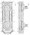
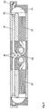
- the essential parts of the system consist of two impellers 1 of side ring duct blowers which rotate in the direction of the arrow as indicated.
- the laser gas is moved in the ring channel 2 above the impellers.
- the ring channel 2 opens into two longitudinal tubes 3, which tangentially connect the two channels 2 above the impellers.
- the metal intermediate piece 4 between the impellers and the longitudinal tubes serves as a scraper at the mouth of the impellers and directs the gas from the ring channel 2 into the longitudinal tubes 3, which simultaneously serve as laser tubes.
- the laser gas is excited in the isolated section 5 of the longitudinal tubes between the impellers; the gas discharge burns between annular electrodes 6 at high voltage in the insulated tube and the longitudinal tube at ground potential on the other side.
- the laser radiation runs in the interior of the resonator from the end mirror 7 via the deflecting mirror 9 to the coupling mirror 8 and vice versa, the channel 10 being an opening for the beam path without an essential gas flow occurring there.
- the whole system can be cooled with water.
- the cooling surface is sufficient for a laser output of more than 200 W.
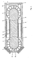
- the ring channel 11 is provided on the outside with an extension 12 on the side of the relevant axis of rotation and at the same time used as a channel for the deflecting beam path, so that the additional channel 10, shown in FIGS. 1 and 2 can be omitted.
- FIGS. 1 to 3 shows a further embodiment which is preferred for high performance and in which paddle wheels 13 are used as impellers.
- paddle wheels 13 are used as impellers.
- ring channel systems 14 and 15 with longitudinal tubes 16 are arranged in the manner of FIGS. 1 to 3. The entire system then contains four laser paths, and the beam must be deflected from one level with two mirrors to the other level.
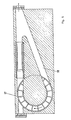
- FIG. 5 A particularly simple version is shown in FIG. 5. Only one impeller 17 is required here, and the return channel 18 is used for particularly efficient cooling of the laser gas.
- ring channels and longitudinal tubes can be equipped with a comparatively large cross section, so that the flow resistances are very low.
- impellers with a diameter of 40 cm and rotating speeds of approx. 4000 rpm, approximately 1000 m 3 of laser gas per hour can be circulated per laser tube. In a system with four laser tubes, this corresponds to an output power of more than 1 kW.
- the output can be increased to the multi-kilowatt range if you work with firmer wheels (e.g. made of titanium) at higher speeds and combine several arrangements by connecting in parallel or in series.
- the parallel connection can be done in such a way that z. B. sets several wheels each on one axis.
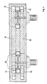
- the parallel connection is realized in the arrangement shown in FIGS. 6 and 7 in such a way that impellers 19 extended in the direction of the axis are used.
- an outer ring channel 20 comes into consideration as the ring channel, and the longitudinal tubes 21, 22 expand into wide channels.
- a preferred embodiment smaller impellers with a high speed of 16,000 rpm or more are used.
- the laser gas is only moved on one side with the impeller 19 and deflected into the laser channel 21 on the other side via a semicircular channel 24.
- the inlet channel 22 is expanded and designed as a cooler.
- the electrodes 25 are arranged at the beginning of the laser channel.
- Fig. 6 shows a section perpendicular through the axis of rotation of the impeller
- Fig. 7 shows a section through the laser channel.
- a doubling of the power with output powers into the multi-kilowatt range can be achieved if two arrangements of this embodiment, as shown in FIG. 1, are added to one another in mirror image. This has the additional advantage that the flow of the laser gas is directed away from the mirrors on both sides and contamination of the mirrors by particles carried in the gas stream is avoided.
- the problem of insulation without much reduction in the active length of the laser tube is also to be solved by using essentially ring-shaped, possibly subdivided intermediate electrodes.
Abstract
Description
Die Erfindung betrifft eine Laseranordnung nach dem Gastransport-Prinzip, mit schneller longitudinaler Gasströmung.The invention relates to a laser arrangement based on the gas transport principle, with a rapid longitudinal gas flow.
Leistung, Verstärkung und Wirkungsgrad der Moleküllaser, insbesondere der COz-Laser, nehmen mit steigender Temperatur im Lasergas ab. Die Abnahme der Leistungsfähigkeit beruht darauf, dass mit zunehmender Temperatur die Linienbreite grösser wird, die Anregungsenergie sich auf eine zunehmende Zahl von Rotationslinien verteilt, die Zahl der desaktivierenden Stösse zunimmt und die Besetzung des Laserendniveaus durch thermische Anregung zunimmt und damit die Inversion abnimmt (K. Gürs, «Laser 74 Optoelectronics», Conference proceedings, S. 30-37).The power, amplification and efficiency of the molecular laser, especially the CO z laser, decrease with increasing temperature in the laser gas. The decrease in performance is due to the fact that the line width increases with increasing temperature, the excitation energy is distributed over an increasing number of rotation lines, the number of deactivating bumps increases and the occupation of the laser end level by thermal excitation increases and thus the inversion decreases (K. Gürs, "Laser 74 Optoelectronics", Conference proceedings, pp. 30-37).
Aus diesem Grund wurden bereits Methoden entwickelt, die Wärme mit dem Lasergas durch Umwälzen und Kühlen des Gases abführen. Geeignete Laser bestehen aus einem aktiven Bereich, in dem das Gas angeregt wird, mit angrenzendem oder integriertem optischen Resonator, aus dem Gasführungssystem mit eingebautem Kühler und einer Pumpe. Da grosse Wärmemengen abzuführen sind, müssen grosse Gasmengen umgepumpt werden. Die entsprechenden bekannten Laser sind gross und aufwendig, ihre Einsatzmöglichkeit ist wegen ihrer Unhandlichkeit begrenzt.For this reason, methods have already been developed that dissipate heat with the laser gas by circulating and cooling the gas. Suitable lasers consist of an active area in which the gas is excited, with an adjacent or integrated optical resonator, the gas routing system with a built-in cooler and a pump. Since large amounts of heat have to be dissipated, large amounts of gas have to be pumped around. The corresponding known lasers are large and complex, their use is limited because of their unwieldiness.
Dieser Nachteil tritt bei den longitudinal durchströmten Lasern besonders in Erscheinung, bei denen - in den bekannten Anordnungen - lange Gasleitungen erforderlich sind. Ausserdem verursachen diese Leitungen einen entsprechend hohen Strömungswiderstand. Dadurch sinkt die Leistungsfähigkeit des Systems, oder man benötigt besonders grosse Pumpen.This disadvantage is particularly evident in the longitudinally flowed through lasers, in which - in the known arrangements - long gas lines are required. In addition, these lines cause a correspondingly high flow resistance. As a result, the performance of the system drops, or particularly large pumps are required.
Bei den transversal durchströmten Systemen ist der Wechselwirkungsweg der angeregten aktiven Moleküle im Laserresonator relativ klein. Da die Leistungsdichte der Laser nicht weit über der Sättigungsleistung liegt, geht auf diese Weise Anregungsenergie verloren, und die Laser haben einen vergleichsweise kleinen Wirkungsgrad von z. B. weniger als ca. 10%. Ausserdem ist die transversale Anregung relativ inhomogen, wodurch sich ungünstige Strahleigenschaften ergeben.In the case of systems with a transversal flow, the interaction path of the excited active molecules in the laser resonator is relatively small. Since the power density of the lasers is not far above the saturation power, excitation energy is lost in this way, and the lasers have a comparatively low efficiency of e.g. B. less than about 10%. In addition, the transverse excitation is relatively inhomogeneous, which results in unfavorable beam properties.
Die angegebenen Nachteile der bekannten Gastransport- bzw. Konvektionslaser konnten bereits durch eine Anordnung beseitigt werden, bei der die Laserkammer als gekühltes Rohr ausgebildet und konzentrisch innerhalb einer Umwälzturbine angeordnet ist (DE-OS 3 121 372). Dadurch wird in der Tat bereits ein wesentlicher Fortschritt gegenüber herkömmlichen Gastransport-Lasern mit longitudinaler. Gasströmung erzielt. Allerdings ist dieser Laser nur mit grossem technischem Aufwand zu realisieren. Besonders aufwendig und auch in der Serienproduktion teuer sind vier Komponenten und zwar
- - die Lager. Wegen des grossen Durchmessers bei Aussenlagerung und der grossen Drehgeschwindigkeit ergibt sich eine sehr grosse Geschwindigkeit der bewegten gegen die stehenden Teile. Das Problem konnte durch Einsatz von Gaslagern gelöst werden.
- - der Antrieb. Als schnellaufendes System (400 U/s) mit hohlem Innenläufer stellt der Motor eine aufwendige Sonderkonstruktion dar.
- -die Beschaufelung. Auch der Umwälzverdichter ist eine Sonderkonstruktion. Besonders ungewöhnlich und schwierig herzustellen ist das System der an einem rotierenden Aussenrohr befestigten Turbinenschaufeln. Auch die Verwendung von Radialverdichtern bringt wegen der damit verbundenen komplizierten Gasführung keine wesentliche Vereinfachung.
- -das Kühlsystem. Die kreissymmetrische Bauweise und die Notwendigkeit einer grossen Kühlleistung machen auch diese Komponente zu einer aufwendigen Konstruktion.
- - camps. Because of the large diameter in the case of external storage and the high rotational speed, there is a very high speed of the moving parts against the stationary parts. The problem could be solved by using gas bearings.
- - the drive. As a high-speed system (400 U / s) with a hollow inner rotor, the motor is a complex special design.
- -blading. The circulation compressor is also a special design. The system of turbine blades attached to a rotating outer tube is particularly unusual and difficult to manufacture. The use of radial compressors does not bring any significant simplification either because of the complicated gas flow involved.
- -the cooling system. The circular symmetrical design and the need for a high cooling capacity also make this component a complex construction.
Im übrigen werden in den bekannten Gastransportlasern Pumpen und Gebläse der verschiedensten Arten verwendet, z.B. Drehschieberpumpen, Roots-Gebläse (K. Gürs, «Laser 75, Opto-Electronics», Conference Proceedings, S. 30-37 oder H. Herbrich und B. Dellith, DE-OS 2925829), Querstromlüfter (J.D. Foster, US-PS 4 099 143) oder Radialgebläse (H.J. Seguin und G. Sedgwick, Appl. Optics 11, 1972, 745-748 oder K. Sasaki u.a., EP-A-0 015 003). In allen Fällen sind die verschiedenen Komponenten jeweils als Teilsysteme mit definierter Funktion getrennt zu identifizieren.Incidentally, pumps and blowers of various types are used in the known gas transport lasers, e.g. Rotary vane pumps, Roots blowers (K. Gürs, "Laser 75, Opto-Electronics", Conference Proceedings, pp. 30-37 or H. Herbrich and B. Dellith, DE-OS 2925829), cross-flow fans (JD Foster, US-PS 4,099,143) or radial blowers (HJ Seguin and G. Sedgwick, Appl. Optics 11, 1972, 745-748 or K. Sasaki et al., EP-A-0 015 003). In all cases, the various components must be identified separately as subsystems with a defined function.
Der vorliegenden Erfindung liegt daher die Aufgabe zugrunde, eine besonders kompakt aufgebaute und leistungsfähige Laseranordnung zu entwickeln, bei der alle Funktionen voll integriert sind, so dass in Kombination mit einer bestimmten Gasführung sehr kurze Gaswege realisiert werden können.The present invention is therefore based on the object of developing a particularly compact and powerful laser arrangement in which all functions are fully integrated, so that very short gas paths can be realized in combination with a specific gas routing.
Diese Aufgabe ist erfindungsgemäss dadurch gelöst, dass zur Gasumwälzung mindestens ein Gebläserad nach Art der Laufräder von Tangentialgebläsen mit angrenzendem Ringkanal vorgesehen ist, dass in den Ringkanal des Gebläserades mindestens zwei Längsrohre (Längskanäle) tangential münden und der Ringkanal zwischen den Längsrohren unterbrochen ist und dass der Ringkanal und die Längsrohre eine Kreislaufstrecke für das Lasergas bilden, wobei mindestens ein Längsrohr als Laserresonator ausgebildet ist. Vorteilhafte Weiterbildungen der erfindungsgemässen Laseranordnung sind in den Unteransprüchen 2 bis 14 erläutert.This object is achieved according to the invention in that at least one impeller in the manner of the impellers of tangential blowers with an adjacent ring duct is provided for gas circulation, that at least two longitudinal pipes (longitudinal ducts) open tangentially in the ring duct of the impeller and the ring duct between the longitudinal ducts is interrupted and that Ring channel and the longitudinal tubes form a circuit for the laser gas, at least one longitudinal tube being designed as a laser resonator. Advantageous developments of the laser arrangement according to the invention are explained in
Die Erfindung wird anhand beiliegender Zeichnung näher erläutert. Es zeigt in schematischer Vereinfachug
- Fig. 1 bis 3 im Horizontal- und Vertikalschnitt, eine bevorzugte Ausführungsform der erfindungsgemässen Anordnung, bei der Ringkanäle sich oberhalb der Laufräder befinden;
- Fig. 4 im Vertikalschnitt eine weitere Ausführungsform, bei der Schaufelräder zur Gasumwälzung vorgesehen sind;
- Fig. 5 im Horizontalschnitt ein erfindungsgemässer Laser mit einem einzigen Laufrad zur Gasumwälzung;
- Fig. 6 und 7 im Horizontal- und Vertikalschnitt eine weitere Ausführungsform, bei der ein in Richtung der Drehachse ausgedehntes Laufrad verwendet und somit ein Parallelschalten mehrerer Systeme ermöglicht wird und
- Fig. 8 im Horizontalschnitt eine Ausführungsform, bei der zwei Anordnungen gemäss Fig. 6 und 7 spiegelbildlich zusammengefügt sind.
- Figures 1 to 3 in horizontal and vertical section, a preferred embodiment of the arrangement according to the invention, in which ring channels are located above the impellers;
- 4 shows a further embodiment in vertical section, in which paddle wheels are provided for gas circulation;
- 5 is a horizontal section of a laser according to the invention with a single impeller for gas circulation;
- 6 and 7 in horizontal and vertical section a further embodiment in which a rich tion of the axis of rotation used extended impeller and thus a parallel connection of several systems is possible and
- Fig. 8 in horizontal section an embodiment in which two arrangements according to FIGS. 6 and 7 are put together in mirror image.
In dem in Fig. 1 und 2 dargestellten Ausführungsbeispiel bestehen die wesentlichen Teile des Systems aus zwei Laufrädern 1 von Seitenringkanalgebläsen, die sich wie angegeben in Pfeilrichtung drehen. Das Lasergas wird im Ringkanal 2 oberhalb der Laufräder mitbewegt. Der Ringkanal 2 mündet in zwei Längsrohre 3, die die beiden Kanäle 2 oberhalb der Laufräder tangential miteinander verbinden. Das Metall-Zwischenstück 4 zwischen den Laufrädern und den Längsrohren dient an der Einmündung der Laufräder als Abstreifer und lenkt das Gas aus dem Ringkanal 2 in die Längsrohre 3, die gleichzeitig als Laserrohre dienen. In dem isolierten Teilstück 5 der Längsrohre zwischen den Laufrädern wird das Lasergas angeregt; die Gasentladung brennt zwischen ringförmigen auf hoher Spannung liegenden Elektroden 6 im isolierten Rohr und dem auf Erdpotential liegenden Längsrohr auf der anderen Seite. Die Laserstrahlung läuft im Innern des Resonators von dem Endspiegel 7 über die Umlenkspiegel 9 zum Auskoppelspiegel 8 und umgekehrt, wobei der Kanal 10 eine Öffnung für den Strahlengang darstellt, ohne dass dort eine wesentliche Gasströmung auftritt.In the embodiment shown in FIGS. 1 and 2, the essential parts of the system consist of two
Das ganze System kann mit Wasser gekühlt werden. Die Kühlfläche reicht bei glatten Strömungskanälen für eine Laserleistung von mehr als 200 W aus. Durch Einschneiden von Rillen in Längsrichtung in den Ringkanälen und den Längsrohren kann die Oberfläche und damit die Kühlfläche vergrössert und eine entsprechend höhere Laserleistung erreicht werden.The whole system can be cooled with water. With smooth flow channels, the cooling surface is sufficient for a laser output of more than 200 W. By cutting grooves in the longitudinal direction in the ring channels and the longitudinal tubes, the surface and thus the cooling surface can be enlarged and a correspondingly higher laser power can be achieved.
In einer zweiten in Fig. 3 gezeigten Version wird der Ringkanal 11 auf der Aussenseite mit einer Erweiterung 12 auf der Seite der betreffenden Drehachse versehen und gleichzeitig als Kanal für den Umlenkstrahlengang genutzt, so dass der zusätzliche Kanal 10, dargestellt in Fig. 1 und 2 entfallen kann.In a second version shown in FIG. 3, the
In Fig. 4 wird eine weitere, bei hoher Leistung bevorzugte Ausführungsform gezeigt, bei der Schaufelräder 13 als Laufräder eingesetzt werden. In diesem Fall können auf beiden Seiten der Laufräder 13, d. h. oberhalb und unterhalb Ringkanalsysteme 14 und 15 mit Längsrohren 16 nach Art von Fig. 1 bis 3 angeordnet werden. Das Gesamtsystem enthält dann vier Laserstrecken, und der Strahl muss von einer Ebene mit zwei Spiegeln in die andere Ebene umgelenkt werden.4 shows a further embodiment which is preferred for high performance and in which
Eine besonders einfache Version wird in Fig. 5 dargestellt. Hierbei wird nur ein Laufrad 17 benötigt, und der Rücklaufkanal 18 wird zur besonders effizienten Kühlung des Lasergases genutzt.A particularly simple version is shown in FIG. 5. Only one
Bei allen Ausführungsformen können Ringkanäle und Längsrohre mit einem vergleichsweise grossen Querschnitt ausgestattet werden, so dass die Strömungswiderstände sehr gering sind. Bei Laufrädern mit 40 cm Durchmesser und Drehgeschwindigkeiten von ca. 4000 U/min können pro Laserrohr annähernd 1000 m3 Lasergas pro Stunde umgewälzt werden. Dem entspricht bei einem System mit vier Laserrohren eine Ausgangsleistung von mehr als 1 kW. Die Leistung lässt sich bis in den Multikilowatt-Bereich erhöhen, wenn man mit festeren Laufrädern (z. B. aus Titan) bei grösseren Drehgeschwindigkeiten arbeitet und mehrere Anordnungen durch Parallel- oder Hintereinanderschalten kombiniert.In all embodiments, ring channels and longitudinal tubes can be equipped with a comparatively large cross section, so that the flow resistances are very low. With impellers with a diameter of 40 cm and rotating speeds of approx. 4000 rpm, approximately 1000 m 3 of laser gas per hour can be circulated per laser tube. In a system with four laser tubes, this corresponds to an output power of more than 1 kW. The output can be increased to the multi-kilowatt range if you work with firmer wheels (e.g. made of titanium) at higher speeds and combine several arrangements by connecting in parallel or in series.
Das Parallelschalten kann in der Weise geschehen, dass man z. B. mehrere Laufräder jeweils auf eine Achse setzt. Das Parallelschalten wird bei der in Fig. 6 und 7 gezeigten Anordnung in der Weise realisiert, dass in Richtung der Achse ausgedehnte Laufräder 19 verwendet werden. In diesem Fall kommt als Ringkanal ein Aussenringkanal 20 in Betracht, und die Längsrohre 21, 22 erweitern sich zu breiten Kanälen. Allerdings hat sich als vorteilhaft erwiesen, die Längskanäle 21, 22 wieder in Laserrohre zu unterteilen. Durch Spiegel 23 wird die Strahlung von einem Rohr in das nächste umgelenkt.The parallel connection can be done in such a way that z. B. sets several wheels each on one axis. The parallel connection is realized in the arrangement shown in FIGS. 6 and 7 in such a way that impellers 19 extended in the direction of the axis are used. In this case, an
In einer bevorzugten Ausführungsform kommen kleinere Laufräder mit hoher Drehzahl von 16 000 U/min oder mehr zur Verwendung. Das Lasergas wird nur auf einer Seite mit dem Laufrad 19 bewegt und auf der anderen Seite über einem halbkreisförmigen Kanal 24 in den Laserkanal 21 umgelenkt. Der Hinlaufkanal 22 ist erweitert und als Kühler ausgebildet. Am Anfang des Laserkanals sind die Elektroden 25 angeordnet. Fig. 6 zeigt einen Schnitt senkrecht durch die Drehachse des Laufrads, Fig. 7 einen Schnitt durch den Laserkanal.In a preferred embodiment, smaller impellers with a high speed of 16,000 rpm or more are used. The laser gas is only moved on one side with the
Eine Verdoppelung der Leistung mit Ausgangsleistungen bis in den Multikilowatt-Bereich lässt sich erzielen, wenn man zwei Anordnungen dieser Ausführungsform, wie in Fig. dargestellt, spiegelbildlich aneinanderfügt. Hierbei ergibt sich der zusätzliche Vorteil, dass die Strömung des Lasergases auf beiden Seiten von den Spiegeln weggerichtet ist und eine Verschmutzung der Spiegel durch im Gasstrom mitgeführte Partikel vermieden wird.A doubling of the power with output powers into the multi-kilowatt range can be achieved if two arrangements of this embodiment, as shown in FIG. 1, are added to one another in mirror image. This has the additional advantage that the flow of the laser gas is directed away from the mirrors on both sides and contamination of the mirrors by particles carried in the gas stream is avoided.
Als vorteilhaft hat sich ferner erwiesen, den Laser nach Fig.6 und 7 in Modulbauweise, z.B. Teile (a), (b) und (c) auszuführen. Aus herstellungstechnischen Gründen ist es zweckmässig, das Antriebsteil mit Laufrad (Teil a) auf der einen Seite, das Endstück mit Umlenkkanal (Teil c) auf der anderen Seite sowie das Zwischenstück (Teil b) mit Kühler und Laserkanal jeweils getrennt zu fertigen und vakuumdicht mit Schrauben zu verbinden.It has also proven to be advantageous to use the laser according to FIGS. 6 and 7 in a modular design, e.g. Execute parts (a), (b) and (c). For manufacturing reasons, it is advisable to manufacture the drive part with impeller (part a) on one side, the end piece with deflection channel (part c) on the other side and the intermediate piece (part b) with cooler and laser channel separately and vacuum-tight Connect screws.
Damit ergibt sich auch die Möglichkeit, das Zwischenteil b mit Kühler aus einem isolierendem Material herzustellen und das Laserrohr in grosser Länge als Entladungskanal zu nutzen. Eine zweite Möglichkeit besteht darin, nicht das Mittelteil (b) mit Kühler sondern das Endstück (c) mit Umlenkkanal aus einem isolierenden Werkstoff herzustellen.This also makes it possible to produce the intermediate part b with a cooler from an insulating material and to use the laser tube over a large length as a discharge channel. A second possibility is not to produce the middle part (b) with a cooler but the end piece (c) with a deflection channel from an insulating material.
Das Problem der Isolierung ohne grosse Reduzierung der aktiven Länge des Laserrohres ist ferner auch durch Verwendung von im wesentlichen ringförmigen eventuell unterteilten Zwischenelektroden zu lösen.The problem of insulation without much reduction in the active length of the laser tube is also to be solved by using essentially ring-shaped, possibly subdivided intermediate electrodes.
Claims (15)
Priority Applications (1)
| Application Number | Priority Date | Filing Date | Title |
|---|---|---|---|
| AT83105117T ATE38300T1 (en) | 1982-12-11 | 1983-05-24 | LASER ARRANGEMENT. |
Applications Claiming Priority (2)
| Application Number | Priority Date | Filing Date | Title |
|---|---|---|---|
| DE19823245958 DE3245958A1 (en) | 1982-12-11 | 1982-12-11 | LASER ARRANGEMENT |
| DE3245958 | 1982-12-11 |
Publications (3)
| Publication Number | Publication Date |
|---|---|
| EP0111044A2 EP0111044A2 (en) | 1984-06-20 |
| EP0111044A3 EP0111044A3 (en) | 1986-12-03 |
| EP0111044B1 true EP0111044B1 (en) | 1988-10-26 |
Family
ID=6180470
Family Applications (1)
| Application Number | Title | Priority Date | Filing Date |
|---|---|---|---|
| EP83105117A Expired EP0111044B1 (en) | 1982-12-11 | 1983-05-24 | Laser device |
Country Status (6)
| Country | Link |
|---|---|
| US (1) | US4635270A (en) |
| EP (1) | EP0111044B1 (en) |
| JP (1) | JPS59117183A (en) |
| AT (1) | ATE38300T1 (en) |
| CA (1) | CA1206573A (en) |
| DE (2) | DE3245958A1 (en) |
Cited By (18)
| Publication number | Priority date | Publication date | Assignee | Title |
|---|---|---|---|---|
| US7824345B2 (en) | 2003-12-22 | 2010-11-02 | Boston Scientific Scimed, Inc. | Medical device with push force limiter |
| US7841994B2 (en) | 2007-11-02 | 2010-11-30 | Boston Scientific Scimed, Inc. | Medical device for crossing an occlusion in a vessel |
| US7850623B2 (en) | 2005-10-27 | 2010-12-14 | Boston Scientific Scimed, Inc. | Elongate medical device with continuous reinforcement member |
| US7878984B2 (en) | 2002-07-25 | 2011-02-01 | Boston Scientific Scimed, Inc. | Medical device for navigation through anatomy and method of making same |
| US7914466B2 (en) | 1995-12-07 | 2011-03-29 | Precision Vascular Systems, Inc. | Medical device with collapse-resistant liner and method of making same |
| US7914467B2 (en) | 2002-07-25 | 2011-03-29 | Boston Scientific Scimed, Inc. | Tubular member having tapered transition for use in a medical device |
| US8022331B2 (en) | 2003-02-26 | 2011-09-20 | Boston Scientific Scimed, Inc. | Method of making elongated medical devices |
| US8048060B2 (en) | 2003-03-27 | 2011-11-01 | Boston Scientific Scimed, Inc. | Medical device |
| US8105246B2 (en) | 2007-08-03 | 2012-01-31 | Boston Scientific Scimed, Inc. | Elongate medical device having enhanced torque and methods thereof |
| US8377035B2 (en) | 2003-01-17 | 2013-02-19 | Boston Scientific Scimed, Inc. | Unbalanced reinforcement members for medical device |
| US8376961B2 (en) | 2008-04-07 | 2013-02-19 | Boston Scientific Scimed, Inc. | Micromachined composite guidewire structure with anisotropic bending properties |
| US8409114B2 (en) | 2007-08-02 | 2013-04-02 | Boston Scientific Scimed, Inc. | Composite elongate medical device including distal tubular member |
| US8449526B2 (en) | 2001-07-05 | 2013-05-28 | Boston Scientific Scimed, Inc. | Torqueable soft tip medical device and method of usage |
| US8535243B2 (en) | 2008-09-10 | 2013-09-17 | Boston Scientific Scimed, Inc. | Medical devices and tapered tubular members for use in medical devices |
| US8551020B2 (en) | 2006-09-13 | 2013-10-08 | Boston Scientific Scimed, Inc. | Crossing guidewire |
| US8556914B2 (en) | 2006-12-15 | 2013-10-15 | Boston Scientific Scimed, Inc. | Medical device including structure for crossing an occlusion in a vessel |
| US8821477B2 (en) | 2007-08-06 | 2014-09-02 | Boston Scientific Scimed, Inc. | Alternative micromachined structures |
| US9445784B2 (en) | 2005-09-22 | 2016-09-20 | Boston Scientific Scimed, Inc | Intravascular ultrasound catheter |
Families Citing this family (23)
| Publication number | Priority date | Publication date | Assignee | Title |
|---|---|---|---|---|
| DE3600124A1 (en) * | 1986-01-04 | 1987-07-16 | Fortuna Werke Maschf Ag | BLOWERS FOR CIRCUITING LARGE QUANTITIES OF GAS, IN PARTICULAR FOR HIGH-PERFORMANCE LASERS |
| US4817111A (en) * | 1987-03-20 | 1989-03-28 | Prc Corp. | Gas laser apparatus, method and turbine compressor therefor |
| US4975925A (en) * | 1989-11-01 | 1990-12-04 | The Spectranetics Corporation | Unlubricated bearings for gas lasers |
| AT407898B (en) * | 1993-02-23 | 2001-07-25 | Wilfried Stummer | LIFTING PISTON ENGINE WITH STROKE ARRANGED ARRANGED ALONG THE CYLINDER AXLE |
| US6931046B1 (en) * | 2000-09-14 | 2005-08-16 | The Regents Of The University Of California | High power laser having a trivalent liquid host |
| US20040167437A1 (en) * | 2003-02-26 | 2004-08-26 | Sharrow James S. | Articulating intracorporal medical device |
| RU2270499C2 (en) * | 2004-05-21 | 2006-02-20 | Научное учреждение "Отдельное конструкторское бюро лазерной техники при СО РАН", (НУ ОКБ лазерной техники при СО РАН) | Flowing gas laser |
| US20070083132A1 (en) * | 2005-10-11 | 2007-04-12 | Sharrow James S | Medical device coil |
| US20080262474A1 (en) * | 2007-04-20 | 2008-10-23 | Boston Scientific Scimed, Inc. | Medical device |
| US20090036832A1 (en) * | 2007-08-03 | 2009-02-05 | Boston Scientific Scimed, Inc. | Guidewires and methods for manufacturing guidewires |
| US20090043228A1 (en) * | 2007-08-06 | 2009-02-12 | Boston Scientific Scimed, Inc. | Laser shock peening of medical devices |
| US9808595B2 (en) | 2007-08-07 | 2017-11-07 | Boston Scientific Scimed, Inc | Microfabricated catheter with improved bonding structure |
| US20100063479A1 (en) * | 2008-09-10 | 2010-03-11 | Boston Scientific Scimed, Inc. | Small profile, tubular component design and method of manufacture |
| US8795254B2 (en) * | 2008-12-10 | 2014-08-05 | Boston Scientific Scimed, Inc. | Medical devices with a slotted tubular member having improved stress distribution |
| RU2411619C1 (en) * | 2009-10-15 | 2011-02-10 | Александр Васильевич Краснов | High-frequency discharge excited gas laser |
| US8137293B2 (en) | 2009-11-17 | 2012-03-20 | Boston Scientific Scimed, Inc. | Guidewires including a porous nickel-titanium alloy |
| EP2552530A1 (en) | 2010-03-31 | 2013-02-06 | Boston Scientific Scimed, Inc. | Guidewire with a flexural rigidity profile |
| WO2012106628A1 (en) | 2011-02-04 | 2012-08-09 | Boston Scientific Scimed, Inc. | Guidewires and methods for making and using the same |
| US9072874B2 (en) | 2011-05-13 | 2015-07-07 | Boston Scientific Scimed, Inc. | Medical devices with a heat transfer region and a heat sink region and methods for manufacturing medical devices |
| US9901706B2 (en) | 2014-04-11 | 2018-02-27 | Boston Scientific Scimed, Inc. | Catheters and catheter shafts |
| US11351048B2 (en) | 2015-11-16 | 2022-06-07 | Boston Scientific Scimed, Inc. | Stent delivery systems with a reinforced deployment sheath |
| US11095088B1 (en) | 2018-02-21 | 2021-08-17 | Zoyka Llc | Multi-pass coaxial molecular gas laser |
| EP3594498B1 (en) | 2019-11-06 | 2022-01-05 | Pfeiffer Vacuum Gmbh | System with a recirculation device |
Family Cites Families (8)
| Publication number | Priority date | Publication date | Assignee | Title |
|---|---|---|---|---|
| US4099143A (en) * | 1977-01-14 | 1978-07-04 | Universal Laser Corp. | Gas recirculating stabilized laser |
| FR2449346A1 (en) * | 1979-02-16 | 1980-09-12 | Comp Generale Electricite | GAS LASER |
| JPS55113391A (en) * | 1979-02-21 | 1980-09-01 | Hitachi Ltd | Gas flow type laser device |
| US4283686A (en) * | 1979-03-21 | 1981-08-11 | Avco Everett Research Laboratory, Inc. | Laser operation with closed gas and tuned duct pulsing |
| GB2083687B (en) * | 1980-08-21 | 1984-02-01 | Secr Defence | Circulating gas laser |
| EP0065761B1 (en) * | 1981-05-29 | 1985-11-27 | Battelle-Institut e.V. | Laser device |
| JPS5843588A (en) * | 1981-09-09 | 1983-03-14 | Hitachi Ltd | Laser generating device |
| US4426705A (en) * | 1981-10-06 | 1984-01-17 | The United States Of America As Represented By The Secretary Of The Air Force | Double electric discharge coaxial laser |
-
1982
- 1982-12-11 DE DE19823245958 patent/DE3245958A1/en not_active Withdrawn
-
1983
- 1983-05-24 AT AT83105117T patent/ATE38300T1/en not_active IP Right Cessation
- 1983-05-24 DE DE8383105117T patent/DE3378338D1/en not_active Expired
- 1983-05-24 EP EP83105117A patent/EP0111044B1/en not_active Expired
- 1983-12-08 CA CA000442831A patent/CA1206573A/en not_active Expired
- 1983-12-09 JP JP58232639A patent/JPS59117183A/en active Granted
- 1983-12-12 US US06/560,378 patent/US4635270A/en not_active Expired - Fee Related
Cited By (31)
| Publication number | Priority date | Publication date | Assignee | Title |
|---|---|---|---|---|
| US7914466B2 (en) | 1995-12-07 | 2011-03-29 | Precision Vascular Systems, Inc. | Medical device with collapse-resistant liner and method of making same |
| US8449526B2 (en) | 2001-07-05 | 2013-05-28 | Boston Scientific Scimed, Inc. | Torqueable soft tip medical device and method of usage |
| US8939916B2 (en) | 2002-07-25 | 2015-01-27 | Precision Vascular Systems, Inc. | Medical device for navigation through anatomy and method of making same |
| US7878984B2 (en) | 2002-07-25 | 2011-02-01 | Boston Scientific Scimed, Inc. | Medical device for navigation through anatomy and method of making same |
| US8932235B2 (en) | 2002-07-25 | 2015-01-13 | Precision Vascular Systems, Inc. | Medical device for navigation through anatomy and method of making same |
| US7914467B2 (en) | 2002-07-25 | 2011-03-29 | Boston Scientific Scimed, Inc. | Tubular member having tapered transition for use in a medical device |
| US8048004B2 (en) | 2002-07-25 | 2011-11-01 | Precision Vascular Systems, Inc. | Medical device for navigation through anatomy and method of making same |
| US8915865B2 (en) | 2002-07-25 | 2014-12-23 | Precision Vascular Systems, Inc. | Medical device for navigation through anatomy and method of making same |
| US8900163B2 (en) | 2002-07-25 | 2014-12-02 | Precision Vascular Systems, Inc. | Medical device for navigation through anatomy and method of making same |
| US8870790B2 (en) | 2002-07-25 | 2014-10-28 | Boston Scientific Scimed, Inc. | Medical device for navigation through anatomy and method of making same |
| US8936558B2 (en) | 2002-07-25 | 2015-01-20 | Precision Vascular Systems, Inc. | Medical device for navigation through anatomy and method of making same |
| US8257279B2 (en) | 2002-07-25 | 2012-09-04 | Boston Scientific Scimed, Inc. | Medical device for navigation through anatomy and method of making same |
| US8377035B2 (en) | 2003-01-17 | 2013-02-19 | Boston Scientific Scimed, Inc. | Unbalanced reinforcement members for medical device |
| US8022331B2 (en) | 2003-02-26 | 2011-09-20 | Boston Scientific Scimed, Inc. | Method of making elongated medical devices |
| US8636716B2 (en) | 2003-03-27 | 2014-01-28 | Boston Scientific Scimed, Inc. | Medical device |
| US9023011B2 (en) | 2003-03-27 | 2015-05-05 | Boston Scientific Scimed, Inc. | Medical device |
| US8182465B2 (en) | 2003-03-27 | 2012-05-22 | Boston Scientific Scimed, Inc. | Medical device |
| US8048060B2 (en) | 2003-03-27 | 2011-11-01 | Boston Scientific Scimed, Inc. | Medical device |
| US7824345B2 (en) | 2003-12-22 | 2010-11-02 | Boston Scientific Scimed, Inc. | Medical device with push force limiter |
| US9445784B2 (en) | 2005-09-22 | 2016-09-20 | Boston Scientific Scimed, Inc | Intravascular ultrasound catheter |
| US8231551B2 (en) | 2005-10-27 | 2012-07-31 | Boston Scientific Scimed, Inc. | Elongate medical device with continuous reinforcement member |
| US7850623B2 (en) | 2005-10-27 | 2010-12-14 | Boston Scientific Scimed, Inc. | Elongate medical device with continuous reinforcement member |
| US8551020B2 (en) | 2006-09-13 | 2013-10-08 | Boston Scientific Scimed, Inc. | Crossing guidewire |
| US8556914B2 (en) | 2006-12-15 | 2013-10-15 | Boston Scientific Scimed, Inc. | Medical device including structure for crossing an occlusion in a vessel |
| US9375234B2 (en) | 2006-12-15 | 2016-06-28 | Boston Scientific Scimed, Inc. | Medical device including structure for crossing an occlusion in a vessel |
| US8409114B2 (en) | 2007-08-02 | 2013-04-02 | Boston Scientific Scimed, Inc. | Composite elongate medical device including distal tubular member |
| US8105246B2 (en) | 2007-08-03 | 2012-01-31 | Boston Scientific Scimed, Inc. | Elongate medical device having enhanced torque and methods thereof |
| US8821477B2 (en) | 2007-08-06 | 2014-09-02 | Boston Scientific Scimed, Inc. | Alternative micromachined structures |
| US7841994B2 (en) | 2007-11-02 | 2010-11-30 | Boston Scientific Scimed, Inc. | Medical device for crossing an occlusion in a vessel |
| US8376961B2 (en) | 2008-04-07 | 2013-02-19 | Boston Scientific Scimed, Inc. | Micromachined composite guidewire structure with anisotropic bending properties |
| US8535243B2 (en) | 2008-09-10 | 2013-09-17 | Boston Scientific Scimed, Inc. | Medical devices and tapered tubular members for use in medical devices |
Also Published As
| Publication number | Publication date |
|---|---|
| EP0111044A3 (en) | 1986-12-03 |
| EP0111044A2 (en) | 1984-06-20 |
| US4635270A (en) | 1987-01-06 |
| DE3378338D1 (en) | 1988-12-01 |
| CA1206573A (en) | 1986-06-24 |
| DE3245958A1 (en) | 1984-06-14 |
| JPS59117183A (en) | 1984-07-06 |
| JPH0357631B2 (en) | 1991-09-02 |
| ATE38300T1 (en) | 1988-11-15 |
Similar Documents
| Publication | Publication Date | Title |
|---|---|---|
| EP0111044B1 (en) | Laser device | |
| EP0111045B1 (en) | Laser device | |
| EP0065761B1 (en) | Laser device | |
| DE69820971T2 (en) | Cross flow fan with flow stabilizer | |
| EP2615299A1 (en) | Nacelle on a wind turbine mast | |
| EP0376178A1 (en) | Machine tool with motor spindle cooling | |
| CH532199A (en) | Axial turbo molecular pump | |
| EP0427229A2 (en) | Laser | |
| EP1006644A2 (en) | Gas cooled electrical machine with axial ventilator | |
| DE3344714C2 (en) | ||
| DE3335410A1 (en) | HIGH-PERFORMANCE LASERS | |
| DE1628361B2 (en) | CENTRIFUGAL FAN | |
| DE3643735C2 (en) | ||
| DE3330238A1 (en) | HIGH-PERFORMANCE LASERS | |
| DE3734570C2 (en) | Device for a longitudinally flowing CO¶2¶ power laser | |
| EP0089974B1 (en) | Laser | |
| DE1153914B (en) | Image projector with cooling fan | |
| DE3235170A1 (en) | Gas transport laser, in particular an axial current CO2 gas transport laser | |
| WO2016142192A1 (en) | Electric machine comprising a baffle | |
| DE2346219C3 (en) | Laser with cooling system | |
| DE19814485A1 (en) | Multistage turbofan for a carbon dioxide laser | |
| DE3031692A1 (en) | Gas transport laser with electrodes - having inlets at ends of laser tube and outlet at centre linked to cooling unit | |
| DE19515704A1 (en) | Cooled diode pumped solid state laser appts. | |
| AT394645B (en) | Longitudinal flow CO2 power laser | |
| DE1628361C3 (en) | Centrifugal fan |
Legal Events
| Date | Code | Title | Description |
|---|---|---|---|
| PUAI | Public reference made under article 153(3) epc to a published international application that has entered the european phase |
Free format text: ORIGINAL CODE: 0009012 |
|
| AK | Designated contracting states |
Designated state(s): AT BE CH DE FR GB IT LI NL SE |
|
| PUAL | Search report despatched |
Free format text: ORIGINAL CODE: 0009013 |
|
| AK | Designated contracting states |
Kind code of ref document: A3 Designated state(s): AT BE CH DE FR GB IT LI NL SE |
|
| 17P | Request for examination filed |
Effective date: 19870515 |
|
| 17Q | First examination report despatched |
Effective date: 19880330 |
|
| RAP1 | Party data changed (applicant data changed or rights of an application transferred) |
Owner name: TZN FORSCHUNGS- UND ENTWICKLUNGSZENTRUM UNTERLUESS |
|
| ITF | It: translation for a ep patent filed |
Owner name: CALVANI SALVI E VERONELLI S.R.L. |
|
| GRAA | (expected) grant |
Free format text: ORIGINAL CODE: 0009210 |
|
| AK | Designated contracting states |
Kind code of ref document: B1 Designated state(s): AT BE CH DE FR GB IT LI NL SE |
|
| REF | Corresponds to: |
Ref document number: 38300 Country of ref document: AT Date of ref document: 19881115 Kind code of ref document: T |
|
| GBT | Gb: translation of ep patent filed (gb section 77(6)(a)/1977) | ||
| REF | Corresponds to: |
Ref document number: 3378338 Country of ref document: DE Date of ref document: 19881201 |
|
| ET | Fr: translation filed | ||
| PLBE | No opposition filed within time limit |
Free format text: ORIGINAL CODE: 0009261 |
|
| STAA | Information on the status of an ep patent application or granted ep patent |
Free format text: STATUS: NO OPPOSITION FILED WITHIN TIME LIMIT |
|
| 26N | No opposition filed | ||
| PGFP | Annual fee paid to national office [announced via postgrant information from national office to epo] |
Ref country code: SE Payment date: 19900404 Year of fee payment: 8 |
|
| PGFP | Annual fee paid to national office [announced via postgrant information from national office to epo] |
Ref country code: DE Payment date: 19900412 Year of fee payment: 8 |
|
| PGFP | Annual fee paid to national office [announced via postgrant information from national office to epo] |
Ref country code: CH Payment date: 19900420 Year of fee payment: 8 Ref country code: AT Payment date: 19900420 Year of fee payment: 8 |
|
| PGFP | Annual fee paid to national office [announced via postgrant information from national office to epo] |
Ref country code: FR Payment date: 19900430 Year of fee payment: 8 |
|
| PGFP | Annual fee paid to national office [announced via postgrant information from national office to epo] |
Ref country code: GB Payment date: 19900522 Year of fee payment: 8 |
|
| PGFP | Annual fee paid to national office [announced via postgrant information from national office to epo] |
Ref country code: BE Payment date: 19900528 Year of fee payment: 8 |
|
| ITTA | It: last paid annual fee | ||
| PGFP | Annual fee paid to national office [announced via postgrant information from national office to epo] |
Ref country code: NL Payment date: 19900531 Year of fee payment: 8 |
|
| PG25 | Lapsed in a contracting state [announced via postgrant information from national office to epo] |
Ref country code: GB Effective date: 19910524 Ref country code: AT Effective date: 19910524 |
|
| PG25 | Lapsed in a contracting state [announced via postgrant information from national office to epo] |
Ref country code: SE Effective date: 19910525 |
|
| PG25 | Lapsed in a contracting state [announced via postgrant information from national office to epo] |
Ref country code: LI Effective date: 19910531 Ref country code: CH Effective date: 19910531 Ref country code: BE Effective date: 19910531 |
|
| BERE | Be: lapsed |
Owner name: TZN FORSCHUNGS- UND ENTWICKLUNGSZENTRUM UNTERLSS Effective date: 19910531 |
|
| PG25 | Lapsed in a contracting state [announced via postgrant information from national office to epo] |
Ref country code: NL Effective date: 19911201 |
|
| NLV4 | Nl: lapsed or anulled due to non-payment of the annual fee | ||
| GBPC | Gb: european patent ceased through non-payment of renewal fee | ||
| PG25 | Lapsed in a contracting state [announced via postgrant information from national office to epo] |
Ref country code: FR Effective date: 19920131 |
|
| REG | Reference to a national code |
Ref country code: CH Ref legal event code: PL |
|
| PG25 | Lapsed in a contracting state [announced via postgrant information from national office to epo] |
Ref country code: DE Effective date: 19920303 |
|
| REG | Reference to a national code |
Ref country code: FR Ref legal event code: ST |
|
| EUG | Se: european patent has lapsed |
Ref document number: 83105117.2 Effective date: 19911209 |