EP0112938A2 - Liquid outlet controller and pouring spout - Google Patents
Liquid outlet controller and pouring spout Download PDFInfo
- Publication number
- EP0112938A2 EP0112938A2 EP82306668A EP82306668A EP0112938A2 EP 0112938 A2 EP0112938 A2 EP 0112938A2 EP 82306668 A EP82306668 A EP 82306668A EP 82306668 A EP82306668 A EP 82306668A EP 0112938 A2 EP0112938 A2 EP 0112938A2
- Authority
- EP
- European Patent Office
- Prior art keywords
- liquid
- liquid outlet
- sleeve
- conduit
- valve
- Prior art date
- Legal status (The legal status is an assumption and is not a legal conclusion. Google has not performed a legal analysis and makes no representation as to the accuracy of the status listed.)
- Withdrawn
Links
Images

Classifications
-
- B—PERFORMING OPERATIONS; TRANSPORTING
- B67—OPENING, CLOSING OR CLEANING BOTTLES, JARS OR SIMILAR CONTAINERS; LIQUID HANDLING
- B67D—DISPENSING, DELIVERING OR TRANSFERRING LIQUIDS, NOT OTHERWISE PROVIDED FOR
- B67D3/00—Apparatus or devices for controlling flow of liquids under gravity from storage containers for dispensing purposes
- B67D3/04—Liquid-dispensing taps or cocks adapted to seal and open tapping holes of casks, e.g. for beer
- B67D3/043—Liquid-dispensing taps or cocks adapted to seal and open tapping holes of casks, e.g. for beer with a closing element having a linear movement, in a direction perpendicular to the seat
- B67D3/044—Liquid-dispensing taps or cocks adapted to seal and open tapping holes of casks, e.g. for beer with a closing element having a linear movement, in a direction perpendicular to the seat and venting means operated automatically with the tap
Definitions
- This invention relates to liquid dispensers and more particularly to dispensers suitable for dispensing liquid from containers and controllers for such liquid dispensers.
- liquid dispensing is required in for instance a refrigerator where a store of cooled drinks such as water or cordial may be kept and some dispensing means is required on the outside of the refrigerator which will allow the contents of the container to be dispensed quickly and cleanly into for instance a glass, cup or other receptacle without having to remove the liquid container from the fridge.
- a store of cooled drinks such as water or cordial
- some dispensing means is required on the outside of the refrigerator which will allow the contents of the container to be dispensed quickly and cleanly into for instance a glass, cup or other receptacle without having to remove the liquid container from the fridge.
- Dispensers such as the one shown in Australian Patent Application No. 29594/77 are known but these are adapted only to dispense known quantities of liquids. This may be suitable when dispensing fixed quantities of spirits for instance but not suitable for dispensing liquids to fill a glass or receptacle without the danger of over filling it.
- the invention is said to reside in a liquid outlet controller including at least two conduits, a first conduit adapted to facilitate from an air inlet to an air outlet, air ingress therethrough and the second conduit adapted to facilitate liquid egress from a liquid inlet to a liquid outlet, only during air passage through the said first conduit and valve means to close each of the said conduits.
- the air inlet is adjacent the air outlet. Further the air inlet conduit may be positioned within the air outlet conduit so as for instance to make the inlet conduit coaxial with the outlet conduit.
- valve means may be actuated by a manually operated device and in a further embodiment the valve means may be actuatable automatically by means of a sleeve having at least one abutment surface, the sleeve being positioned about the second conduit and being resiliently biased in relation to the second conduit such that the valves are normally closed.
- the first conduit being the air inlet conduit
- this air inlet conduit may carry means to actuate each of the valve means. This may be arranged such that the first conduit, the air inlet conduit, sequentially actuates the air valve means and then further movement of the sleeve, and hence the first conduit, actuates the liquid valve means.
- the invention may be said to reside in a liquid dispenser adapted to be secured to an outlet of a liquid holding container to assist in pouring liquid from the container, the dispenser including a body having a passageway passing therethrough, one end of which is adapted to sealably engage around the outlet of the container, the other end of the passageway having in association therewith a control member, the control member being movable with respect to the body so that in a first position a liquid outlet control valve within the passageway is closed and an airlet control valve with a passageway through the liquid outlet control valve is closed, in the second sequential position from the first said position the air inlet control valve is opened with the liquid outlet control valve remaining closed and in a sequential third position from the second position both the liquid outlet control valve and the air inlet control valve are opened.
- control member may comprise a sleeve located about the body, the sleeve being resiliently biased such that both the air inlet control valve and the liquid outlet control valve are normally closed. Pushing on the sleeve such as with the rim of a glass, cup or other receptacle or from the edge of the filling aperture of a petrol tank would cause the sleeve to he moved such as to sequentially open the air inlet and then the liquid outlet control valve.
- barometric pressure upon the liquid already dispensed into the receptacle will be such as to prevent further dispensing of liquid from the receptacle provided air cannot be allowed into the receptacle and this will not occur as the liquid level in the receptacle is such that the air inlet is closed.
- any abutment on the sleeve will of course determine the final level of fluid to be achieved in the receptacle.
- a liquid outlet controller of this type may be provided on for instance a fuel tank where fuel is being dispensed in a liquid form into some other container such as a fuel tank or a lawnmower. It may also be provided as indicated earlier on a liquid container with a liquid outlet on the outside of a refrigerator so that pushing a glass up against the abutment on the spring loaded sleeve will cause dispensing to occur until liquid level has risen in the glass or receptacle to such an extent that the air inlet is blocked and liquid flow will stop, removal of the glass or receptacle then will cause the valves to reseat and seal again.
- one great advantage of the present invention is that by introducing the air at a position above the liquid outlet control valve, laminar flow or pseudo-laminar flow of the liquid out of the dispenser will occur which will prevent slugging and turbulent flow of the liquid.
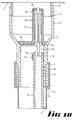
- FIG. 1A, B, and C of the drawings there is shown a portion of a liquid container 1 which has a screw threaded aperture 2 extending therefrom.
- a housing 3 is screwed and sealing means 4 prevents leakage of liquid between the housing and the screw threaded aperture.
- the housing 3 is tapered in the region 5 to provide a valve seating area 6 to be discussed further later.
- the housing 3 extends below the tapered portion 5 in a generally cylindrical manner and is further reduced in diameter at 7 to allow a sleeve 8 resiliently biased by compression spring 9 to slide in contact along the cylindrical portion 10 of the housing 3.
- the spring loaded sleeve also carries by means of an arm 11, an air inlet tube portion 12, which extends from being mounted on the sleeve up into the housing 3.
- a ring 13 fixed to the housing 3 supports the upper end of the air inlet tube portion 12.
- Flanges 14 mounted within the upper end of the tube 12 support a valve actuation rod 15 which extends further up within the housing 3.
- a valve member 16 seats against the valve sealing surfaces 6 to prevent liquid egress from the container in use.
- the valve member 16 has an extension 17 extending up into the upper portion of the housing 3 and it is up this extension 17 that the rod 15 passes to an upper end 18 of the extension upon which an air valve 19 is seated. Movement of the air valve 19 is by means of the rod 15. Movement of the rod 15 is guided within the extension 17 by means of flanges 20 on the rod 15.
- the sleeve 8 contains an abutment surface 21 and this abutment surface 21 includes raised portions 22 such that if the sleeve is inserted completely into the opening of a receptacle into which liquid is being dispensed, the abutments 22 allow air to depart from the receptacle being filled as liquid replaces it.
- This embodiment comprises a screw threaded aperture 30 suitable for fastening onto a liquid container of some sort. From this fastening 30 a housing 31 extends but in this embodiment the sleeve 32 is considerably larger and envelopes most of the housing 31.
- the liquid outlet 33 is formed into the lower end of the sleeve 32 and supports the air inlet tube 34.
- the liquid outlet valve 35 is essentially free floating but is held on its seat in 36 in a normally closed position by means of the helical spring 37 acting upon the sleeve 32,which acts on the liquid outlet valve 35 by means of the air inlet tube 34.
- the air inlet valve 38 is mounted on the upper end of the air inlet tube 34. At least one aperture 39 allows air ingress from the tube 34 into the space above the valve 35.
- the actual means for lifting the valve 35 are wings 40 affixed to the air inlet tube 34 which lift the valve upon movement upwards of the sleeve 32.
- Abutment means 41 are provided on the side of the sleeve 32 to facilitate compression of the spring 37 and hence opening of the valves 38 and 35 sequentially.
- the materials of construction of the liquid dispenser according to this invention may be of any suitable material and particularly plastics for the dispenser would be suitable and with the valve portions being made of a resilient rubber or plastics material.
- actuation of the air and liquid control valves may be by means of a manually operated lever with still the advantage that automatic cut-off of liquid flow will occur.
Abstract
Description
- This invention relates to liquid dispensers and more particularly to dispensers suitable for dispensing liquid from containers and controllers for such liquid dispensers.
- It is well known to use various forms of spouts and the like on containers but these have the disadvantage that as liquid is poured from the container, the container must be tipped to allow the spout to enter a funnel or wherever the liquid is required and-during this pouring operation almost invariably some liquid is spilt. It would be-advantageous therefore if a method of dispensing liquid could be devised which would be simple to operate and have a minimum of moving parts yet be able to prevent dispensing until liquid is required.
- It is of course possible to supply taps in liquid spouts but these have the problem that air must be .allowed to get back into a tank during the pouring operation and hence it is desirable that a liquid spout should have an air inlet which will extend into the container in use.
- It is important too that this air inlet be sealed when dispensing is not required so that highly volatile liquids such as petrol or the like will not evaporate when the air inlet is not required.
- Another instance where liquid dispensing is required is in for instance a refrigerator where a store of cooled drinks such as water or cordial may be kept and some dispensing means is required on the outside of the refrigerator which will allow the contents of the container to be dispensed quickly and cleanly into for instance a glass, cup or other receptacle without having to remove the liquid container from the fridge.
- Dispensers such as the one shown in Australian Patent Application No. 29594/77 are known but these are adapted only to dispense known quantities of liquids. This may be suitable when dispensing fixed quantities of spirits for instance but not suitable for dispensing liquids to fill a glass or receptacle without the danger of over filling it.
- As indicated above another problem with dispensing of liquids is that of over filling. Particularly when filling for instance the fuel tank of a lawnmower or the like, it is very difficult to know when the fuel level has reached the top of the tank and often over filling with potentially dangerous consequences can occur. It would be desirable therefore if some method could be found by which automatic cut off of the liquid flow could occur when a container such as. a petrol tank is nearly full.
- It is the object therefore of this invention to overcome at least some. of the above problems.
- In one form therefore the invention is said to reside in a liquid outlet controller including at least two conduits, a first conduit adapted to facilitate from an air inlet to an air outlet, air ingress therethrough and the second conduit adapted to facilitate liquid egress from a liquid inlet to a liquid outlet, only during air passage through the said first conduit and valve means to close each of the said conduits.
- In a preferred embodiment of the controller the air inlet is adjacent the air outlet. Further the air inlet conduit may be positioned within the air outlet conduit so as for instance to make the inlet conduit coaxial with the outlet conduit.
- In one preferred embodiment the valve means may be actuated by a manually operated device and in a further embodiment the valve means may be actuatable automatically by means of a sleeve having at least one abutment surface, the sleeve being positioned about the second conduit and being resiliently biased in relation to the second conduit such that the valves are normally closed.
- In one embodiment of this form the first conduit, being the air inlet conduit, may be affixed to the sleeve so as to move with the sleeve and this air inlet conduit may carry means to actuate each of the valve means. This may be arranged such that the first conduit, the air inlet conduit, sequentially actuates the air valve means and then further movement of the sleeve, and hence the first conduit, actuates the liquid valve means.
- In an alternative form the invention may be said to reside in a liquid dispenser adapted to be secured to an outlet of a liquid holding container to assist in pouring liquid from the container, the dispenser including a body having a passageway passing therethrough, one end of which is adapted to sealably engage around the outlet of the container, the other end of the passageway having in association therewith a control member, the control member being movable with respect to the body so that in a first position a liquid outlet control valve within the passageway is closed and an airlet control valve with a passageway through the liquid outlet control valve is closed, in the second sequential position from the first said position the air inlet control valve is opened with the liquid outlet control valve remaining closed and in a sequential third position from the second position both the liquid outlet control valve and the air inlet control valve are opened.
- In a preferred embodiment of this form of the invention the control member may comprise a sleeve located about the body, the sleeve being resiliently biased such that both the air inlet control valve and the liquid outlet control valve are normally closed. Pushing on the sleeve such as with the rim of a glass, cup or other receptacle or from the edge of the filling aperture of a petrol tank would cause the sleeve to he moved such as to sequentially open the air inlet and then the liquid outlet control valve. For this purpose there may be provided on the sleeve at least one abutment surface.
- The actual principle of operation of the liquid dispenser according to this invention is as follows: Upon actuation of the valve means by one of the processes indicated above with the dispenser outlet inserted into a receptacle of some sort, air will be allowed ingress into the container from which the liquid is being dispensed and liquid will run from the container with the air entering, replacing the liquid departing. With the air inlet also within the receptacle as the liquid level in the receptacle rises it will get to such a stage that air will' be prevented from entering the air inlet conduit and at this stage, as there will be no air to replace liquid leaving the container, liquid flow will cease.
- This is due to the fact that barometric pressure upon the liquid already dispensed into the receptacle will be such as to prevent further dispensing of liquid from the receptacle provided air cannot be allowed into the receptacle and this will not occur as the liquid level in the receptacle is such that the air inlet is closed.
- The result is that dispensing stops and then with removal of the dispenser from the receptacle the slight bit of liquid left in the dispensing conduit will depart as the valves are shut and by this means overfilling will be prevented.
- The spacing of any abutment on the sleeve will of course determine the final level of fluid to be achieved in the receptacle.
- It will be realised that a liquid outlet controller of this type may be provided on for instance a fuel tank where fuel is being dispensed in a liquid form into some other container such as a fuel tank or a lawnmower. It may also be provided as indicated earlier on a liquid container with a liquid outlet on the outside of a refrigerator so that pushing a glass up against the abutment on the spring loaded sleeve will cause dispensing to occur until liquid level has risen in the glass or receptacle to such an extent that the air inlet is blocked and liquid flow will stop, removal of the glass or receptacle then will cause the valves to reseat and seal again.
- It has been found that one great advantage of the present invention is that by introducing the air at a position above the liquid outlet control valve, laminar flow or pseudo-laminar flow of the liquid out of the dispenser will occur which will prevent slugging and turbulent flow of the liquid.
- To more clearly explain the invention however reference will be mnde to the accompanying illustrations which show various methods by which the present invention may be carried out as follows:
- FIG. 1, parts A, B, and C, show the various steps of actuation of the various valves and spring loaded sleeve,
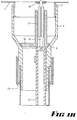
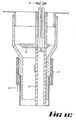
- FIG. 2, parts A, B, and C, show the various stages of actuation of an alternative form of liquid dispenser and
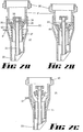
- FIG. 3 and FIG. 4 show preferred embodiments of a dispenser suitable for mounting on a fuel tank.
- Now looking more closely at FIG. 1A, B, and C, of the drawings there is shown a portion of a
liquid container 1 which has a screw threadedaperture 2 extending therefrom. Onto this screw threadedaperture 2, ahousing 3 is screwed and sealing means 4 prevents leakage of liquid between the housing and the screw threaded aperture. - The
housing 3 is tapered in theregion 5 to provide avalve seating area 6 to be discussed further later. - The
housing 3 extends below thetapered portion 5 in a generally cylindrical manner and is further reduced in diameter at 7 to allow asleeve 8 resiliently biased bycompression spring 9 to slide in contact along thecylindrical portion 10 of thehousing 3. - The spring loaded sleeve also carries by means of an
arm 11, an airinlet tube portion 12, which extends from being mounted on the sleeve up into thehousing 3. Aring 13 fixed to thehousing 3 supports the upper end of the airinlet tube portion 12. -
Flanges 14 mounted within the upper end of thetube 12 support avalve actuation rod 15 which extends further up within thehousing 3. - A
valve member 16 seats against thevalve sealing surfaces 6 to prevent liquid egress from the container in use. Thevalve member 16 has anextension 17 extending up into the upper portion of thehousing 3 and it is up thisextension 17 that therod 15 passes to anupper end 18 of the extension upon which anair valve 19 is seated. Movement of theair valve 19 is by means of therod 15. Movement of therod 15 is guided within theextension 17 by means offlanges 20 on therod 15. - The
sleeve 8 contains anabutment surface 21 and thisabutment surface 21 includes raisedportions 22 such that if the sleeve is inserted completely into the opening of a receptacle into which liquid is being dispensed, theabutments 22 allow air to depart from the receptacle being filled as liquid replaces it. - Now that the various components have been described the action of the dispenser will be described in relation to each of the drawings, Figures 1A,1B, and 1C. In the view shown in Figure 1 both the
air inlet valve 19 and theliquid outlet valve 16 are closed and neither air can enter the container or liquid can leave the container. - In Figure 1B the
abutment surface 22 has been depressed against an abutment shown generally as anarrow 23 to such an extent that the upper end of thetube 12 has abutted thevalve 16 but not yet lifted the valve off itsseat 6. At the same time therod 15 has moved upwards through theextension 17 and theair inlet valve 19 has opened. - In the third sequential position shown in Figure 1C further movement of the sleeve against the
abutment 23 has caused thevalve 16 to open which will allow liquid to pass out of the container and with thevalve 19 remaining open, air may enter through theair inlet tube 12 so as to allow smooth liquid flow out pass thevalve 16. - When liquid in the receptacle being filled reaches the level of the bottom of the
sleeve 8 no air may enter the container and hence liquid flow out of the container will cease. At this stage removal of the dispenser form the mouth of the receptacle being filled will cause the valves to return to the positions shown in Figure 1A and the remaining portion of liquid below thevalve 16 in thehousing 3 will be dispensed. - It will of couse be realised that with barometric pressure preventing further liquid flow there is a maximum head of liquid that can be supported but as normal atmospheric pressure will support a head of approximately 30 feet of water then for practical considerations for normal or reasonable sized containers such a dispenser as indicated in this invention will not be practically limited by barometric pressure.
- An alternative embodiment of the invention is shown in Figures 2, 3 and 4 of the illustrations.
- This embodiment comprises a screw threaded
aperture 30 suitable for fastening onto a liquid container of some sort. From this fastening 30 ahousing 31 extends but in this embodiment thesleeve 32 is considerably larger and envelopes most of thehousing 31. Theliquid outlet 33 is formed into the lower end of thesleeve 32 and supports theair inlet tube 34. - The
liquid outlet valve 35 is essentially free floating but is held on its seat in 36 in a normally closed position by means of thehelical spring 37 acting upon thesleeve 32,which acts on theliquid outlet valve 35 by means of the air inlet tube 34.Theair inlet valve 38 is mounted on the upper end of theair inlet tube 34. At least oneaperture 39 allows air ingress from thetube 34 into the space above thevalve 35. - The actual means for lifting the
valve 35 arewings 40 affixed to theair inlet tube 34 which lift the valve upon movement upwards of thesleeve 32. Abutment means 41 are provided on the side of thesleeve 32 to facilitate compression of thespring 37 and hence opening of thevalves - It will be realised that the materials of construction of the liquid dispenser according to this invention may be of any suitable material and particularly plastics for the dispenser would be suitable and with the valve portions being made of a resilient rubber or plastics material.
- It will be realised that this invention is not limtied to the embodiments disclosed but may extend to other embodiments within the scope of the broad disclosure.
- In particular actuation of the air and liquid control valves may be by means of a manually operated lever with still the advantage that automatic cut-off of liquid flow will occur.
Claims (11)
Priority Applications (1)
| Application Number | Priority Date | Filing Date | Title |
|---|---|---|---|
| EP82306668A EP0112938A3 (en) | 1981-06-15 | 1982-12-14 | Liquid outlet controller and pouring spout |
Applications Claiming Priority (2)
| Application Number | Priority Date | Filing Date | Title |
|---|---|---|---|
| AUPE930781 | 1981-06-15 | ||
| EP82306668A EP0112938A3 (en) | 1981-06-15 | 1982-12-14 | Liquid outlet controller and pouring spout |
Publications (2)
| Publication Number | Publication Date |
|---|---|
| EP0112938A2 true EP0112938A2 (en) | 1984-07-11 |
| EP0112938A3 EP0112938A3 (en) | 1984-10-03 |
Family
ID=25642478
Family Applications (1)
| Application Number | Title | Priority Date | Filing Date |
|---|---|---|---|
| EP82306668A Withdrawn EP0112938A3 (en) | 1981-06-15 | 1982-12-14 | Liquid outlet controller and pouring spout |
Country Status (1)
| Country | Link |
|---|---|
| EP (1) | EP0112938A3 (en) |
Cited By (17)
| Publication number | Priority date | Publication date | Assignee | Title |
|---|---|---|---|---|
| FR2608722A1 (en) * | 1986-12-17 | 1988-06-24 | Fabrication Ind | Tap for drawing off a liquid product, with manual control, air inlet and automatic closure for various tanks |
| DE3731820A1 (en) * | 1987-09-22 | 1989-04-13 | Bosch Siemens Hausgeraete | Tapping valve, especially for dispensing drinks |
| EP0422387A2 (en) * | 1989-09-05 | 1991-04-17 | Firma Alfred Kuehmichel | Filling funnel |
| US5118015A (en) * | 1989-09-05 | 1992-06-02 | Scholle Corporation | Method and apparatus for dispensing liquid |
| WO1999036349A1 (en) * | 1998-01-16 | 1999-07-22 | Waddington & Duval Limited | Tap with incorporated air passageway |
| WO2000002796A2 (en) * | 1998-07-10 | 2000-01-20 | Wax Technology S.A.S. | Apparatus and method for dispensing fluid from a container |
| WO2001004042A1 (en) * | 1999-07-12 | 2001-01-18 | Wax Technology S.A.S. | Apparatus for dispensing a fluid from container means |
| EP1190985A3 (en) * | 2000-09-26 | 2002-06-26 | Whirlpool Corporation | Drink dispenser device for domestic refrigerators |
| WO2003027547A3 (en) * | 2001-09-28 | 2003-07-31 | Colder Prod Co | Closure valve for fluid dispensing |
| EP1466835A2 (en) * | 2003-04-08 | 2004-10-13 | Sofiplast | Stopcock with pushbutton for carafes and the like |
| NL1030454C2 (en) * | 2005-11-17 | 2007-05-21 | Bravilor Holding Bv | Drain valve for a beverage reservoir and beverage reservoir provided with such a drain valve. |
| WO2009033277A1 (en) | 2007-09-12 | 2009-03-19 | Vachon Leandre | Auto-vented automatic stop flow pouring spout |
| US20110139829A1 (en) * | 2009-12-16 | 2011-06-16 | Techniplast | Filling device |
| US10472137B2 (en) | 2017-11-14 | 2019-11-12 | Le Groupe Dsd Inc. | Vented spout for a liquid storage container |
| US11479391B2 (en) | 2018-04-16 | 2022-10-25 | Le Groupe Dsd Inc. | Vented spout for a liquid storage container |
| US11713169B2 (en) | 2018-12-21 | 2023-08-01 | Le Groupe Dsd Inc. | Vented spout for a liquid storage container |
| US11827424B2 (en) | 2019-02-01 | 2023-11-28 | Le Groupe Dsd Inc. | Vented spout for a liquid storage container |
Citations (3)
| Publication number | Priority date | Publication date | Assignee | Title |
|---|---|---|---|---|
| US2272208A (en) * | 1939-01-28 | 1942-02-10 | Jorgensen Karl | Bottle filling mechanism |
| DE1182977B (en) * | 1963-06-12 | 1964-12-03 | Enzinger Union Werke Ag | Mass filling valve for vacuum filler |
| US3207190A (en) * | 1964-01-03 | 1965-09-21 | Huffman Mfg Company | Battery filler |
-
1982
- 1982-12-14 EP EP82306668A patent/EP0112938A3/en not_active Withdrawn
Patent Citations (3)
| Publication number | Priority date | Publication date | Assignee | Title |
|---|---|---|---|---|
| US2272208A (en) * | 1939-01-28 | 1942-02-10 | Jorgensen Karl | Bottle filling mechanism |
| DE1182977B (en) * | 1963-06-12 | 1964-12-03 | Enzinger Union Werke Ag | Mass filling valve for vacuum filler |
| US3207190A (en) * | 1964-01-03 | 1965-09-21 | Huffman Mfg Company | Battery filler |
Cited By (31)
| Publication number | Priority date | Publication date | Assignee | Title |
|---|---|---|---|---|
| FR2608722A1 (en) * | 1986-12-17 | 1988-06-24 | Fabrication Ind | Tap for drawing off a liquid product, with manual control, air inlet and automatic closure for various tanks |
| DE3731820A1 (en) * | 1987-09-22 | 1989-04-13 | Bosch Siemens Hausgeraete | Tapping valve, especially for dispensing drinks |
| EP0422387A2 (en) * | 1989-09-05 | 1991-04-17 | Firma Alfred Kuehmichel | Filling funnel |
| EP0422387A3 (en) * | 1989-09-05 | 1991-09-25 | Firma Alfred Kuehmichel | Filling funnel |
| US5118015A (en) * | 1989-09-05 | 1992-06-02 | Scholle Corporation | Method and apparatus for dispensing liquid |
| US6401752B1 (en) | 1998-01-16 | 2002-06-11 | Waddington & Duval Limited | Tap with incorporated air passageway |
| AU751491B2 (en) * | 1998-01-16 | 2002-08-15 | Waddington & Duval Limited | Tap with incorporated air passageway |
| US6470910B2 (en) | 1998-01-16 | 2002-10-29 | Waddington And Duval Limited | Tap with incorporated air passageway |
| WO1999036349A1 (en) * | 1998-01-16 | 1999-07-22 | Waddington & Duval Limited | Tap with incorporated air passageway |
| WO2000002796A2 (en) * | 1998-07-10 | 2000-01-20 | Wax Technology S.A.S. | Apparatus and method for dispensing fluid from a container |
| WO2000002796A3 (en) * | 1998-07-10 | 2000-04-20 | Wax Technology S A S | Apparatus and method for dispensing fluid from a container |
| WO2001004042A1 (en) * | 1999-07-12 | 2001-01-18 | Wax Technology S.A.S. | Apparatus for dispensing a fluid from container means |
| EP1190985A3 (en) * | 2000-09-26 | 2002-06-26 | Whirlpool Corporation | Drink dispenser device for domestic refrigerators |
| US6916007B2 (en) | 2001-09-28 | 2005-07-12 | Colder Products Company | Closure valve apparatus for fluid dispensing |
| WO2003027547A3 (en) * | 2001-09-28 | 2003-07-31 | Colder Prod Co | Closure valve for fluid dispensing |
| EP1466835A2 (en) * | 2003-04-08 | 2004-10-13 | Sofiplast | Stopcock with pushbutton for carafes and the like |
| EP1466835A3 (en) * | 2003-04-08 | 2006-05-17 | Sofiplast | Stopcock with pushbutton for carafes and the like |
| NL1030454C2 (en) * | 2005-11-17 | 2007-05-21 | Bravilor Holding Bv | Drain valve for a beverage reservoir and beverage reservoir provided with such a drain valve. |
| US8561858B2 (en) | 2007-09-12 | 2013-10-22 | Le Groupe Dsd Inc. | Auto-vented automatic stop flow pouring spout |
| EP2285731A1 (en) * | 2007-09-12 | 2011-02-23 | Léandre Vachon | Auto-vented automatic stop flow pouring spout |
| EP2285731A4 (en) * | 2007-09-12 | 2012-04-18 | Leandre Vachon | Auto-vented automatic stop flow pouring spout |
| US8403185B2 (en) | 2007-09-12 | 2013-03-26 | Leandre Vachon | Auto-vented automatic stop flow pouring spout |
| WO2009033277A1 (en) | 2007-09-12 | 2009-03-19 | Vachon Leandre | Auto-vented automatic stop flow pouring spout |
| US20110139829A1 (en) * | 2009-12-16 | 2011-06-16 | Techniplast | Filling device |
| FR2953818A1 (en) * | 2009-12-16 | 2011-06-17 | Techniplast | FILLING DEVICE |
| EP2336079A1 (en) * | 2009-12-16 | 2011-06-22 | Techniplast | Device for filling containers |
| US8668121B2 (en) * | 2009-12-16 | 2014-03-11 | Techniplast | Filling device |
| US10472137B2 (en) | 2017-11-14 | 2019-11-12 | Le Groupe Dsd Inc. | Vented spout for a liquid storage container |
| US11479391B2 (en) | 2018-04-16 | 2022-10-25 | Le Groupe Dsd Inc. | Vented spout for a liquid storage container |
| US11713169B2 (en) | 2018-12-21 | 2023-08-01 | Le Groupe Dsd Inc. | Vented spout for a liquid storage container |
| US11827424B2 (en) | 2019-02-01 | 2023-11-28 | Le Groupe Dsd Inc. | Vented spout for a liquid storage container |
Also Published As
| Publication number | Publication date |
|---|---|
| EP0112938A3 (en) | 1984-10-03 |
Similar Documents
| Publication | Publication Date | Title |
|---|---|---|
| EP0112938A2 (en) | Liquid outlet controller and pouring spout | |
| EP0147891B1 (en) | Pouring spout | |
| CA2268237C (en) | Spill inhibiting spout | |
| EP1212257B1 (en) | Non-spilling detachable pouring spout | |
| US4834151A (en) | Pour spout | |
| EP1324943B1 (en) | Fluid dispensing closure | |
| US5449029A (en) | Fill limit valve assembly | |
| US4314657A (en) | Measuring dispenser | |
| BG64592B1 (en) | Container for storing and dispensing beverages, in particular beer | |
| AU5944990A (en) | Improved pour spout | |
| AU2001296840A1 (en) | Fluid dispensing closure | |
| US4998571A (en) | Overfill valve apparatus | |
| US4712595A (en) | Magnetic safety funnel | |
| US5277233A (en) | Overfill safety adapter | |
| US5564459A (en) | Fob detector | |
| US2893444A (en) | Fluid handling device | |
| US2469746A (en) | Filling device with receptacle operated outlet valve | |
| US6318604B1 (en) | Spill inhibiting spout | |
| AU698520B2 (en) | A measure | |
| US4310038A (en) | Metering valve for beverage containers | |
| US4049162A (en) | Metering valve | |
| US6209567B1 (en) | Foam trap for beer or other gas propelled liquid dispensing systems | |
| US6499518B2 (en) | Nonoverflow, magnetic float valve assembly | |
| US3915357A (en) | Automatic vent valve | |
| JPS59116018A (en) | Liquid weighing partial injecting device |
Legal Events
| Date | Code | Title | Description |
|---|---|---|---|
| PUAI | Public reference made under article 153(3) epc to a published international application that has entered the european phase |
Free format text: ORIGINAL CODE: 0009012 |
|
| AK | Designated contracting states |
Designated state(s): AT BE CH DE FR GB IT LI SE |
|
| PUAL | Search report despatched |
Free format text: ORIGINAL CODE: 0009013 |
|
| RHK1 | Main classification (correction) |
Ipc: B67C 11/06 |
|
| AK | Designated contracting states |
Designated state(s): AT BE CH DE FR GB IT LI SE |
|
| 17P | Request for examination filed |
Effective date: 19841224 |
|
| 17Q | First examination report despatched |
Effective date: 19860305 |
|
| STAA | Information on the status of an ep patent application or granted ep patent |
Free format text: STATUS: THE APPLICATION IS DEEMED TO BE WITHDRAWN |
|
| 18D | Application deemed to be withdrawn |
Effective date: 19860716 |
|
| RIN1 | Information on inventor provided before grant (corrected) |
Inventor name: CLOUGH, RAYMOND JAMES |