EP0113086A2 - Image data processing system - Google Patents
Image data processing system Download PDFInfo
- Publication number
- EP0113086A2 EP0113086A2 EP83112632A EP83112632A EP0113086A2 EP 0113086 A2 EP0113086 A2 EP 0113086A2 EP 83112632 A EP83112632 A EP 83112632A EP 83112632 A EP83112632 A EP 83112632A EP 0113086 A2 EP0113086 A2 EP 0113086A2
- Authority
- EP
- European Patent Office
- Prior art keywords
- field
- scan line
- chain
- document
- pointer
- Prior art date
- Legal status (The legal status is an assumption and is not a legal conclusion. Google has not performed a legal analysis and makes no representation as to the accuracy of the status listed.)
- Granted
Links
Images

Classifications
-
- G—PHYSICS
- G06—COMPUTING; CALCULATING OR COUNTING
- G06V—IMAGE OR VIDEO RECOGNITION OR UNDERSTANDING
- G06V10/00—Arrangements for image or video recognition or understanding
- G06V10/10—Image acquisition
-
- G—PHYSICS
- G06—COMPUTING; CALCULATING OR COUNTING
- G06V—IMAGE OR VIDEO RECOGNITION OR UNDERSTANDING
- G06V30/00—Character recognition; Recognising digital ink; Document-oriented image-based pattern recognition
- G06V30/10—Character recognition
- G06V30/14—Image acquisition
- G06V30/1444—Selective acquisition, locating or processing of specific regions, e.g. highlighted text, fiducial marks or predetermined fields
-
- G—PHYSICS
- G06—COMPUTING; CALCULATING OR COUNTING
- G06V—IMAGE OR VIDEO RECOGNITION OR UNDERSTANDING
- G06V30/00—Character recognition; Recognising digital ink; Document-oriented image-based pattern recognition
- G06V30/10—Character recognition
- G06V30/14—Image acquisition
- G06V30/146—Aligning or centring of the image pick-up or image-field
-
- G—PHYSICS
- G06—COMPUTING; CALCULATING OR COUNTING
- G06V—IMAGE OR VIDEO RECOGNITION OR UNDERSTANDING
- G06V30/00—Character recognition; Recognising digital ink; Document-oriented image-based pattern recognition
- G06V30/10—Character recognition
- G06V30/14—Image acquisition
- G06V30/148—Segmentation of character regions
-
- G—PHYSICS
- G06—COMPUTING; CALCULATING OR COUNTING
- G06V—IMAGE OR VIDEO RECOGNITION OR UNDERSTANDING
- G06V30/00—Character recognition; Recognising digital ink; Document-oriented image-based pattern recognition
- G06V30/10—Character recognition
Definitions
- This invention relates to the processing of data from an image reading system, and has a particular application in the processing of digital image data received from an optical document reading system.
- Documents which are processed by an optical document reading system typically have one or more areas or "image fields" at various locations on the document which contain information in the form of images, such as printed or written alphabetic or numeric characters for example.
- the document reading system scans the document in a series of scan lines and converts the information in the images on the document into an output stream of digital image data.
- the output data stream from the image reading system consists of equal size picture elements or PEL's corresponding to the digital video output from an optical scanner.
- the data stream is usually divided into groups of data elements consisting of a fixed number of PEL'S, each group corresponding to one scan line. Images on the document relating to a particular subject are grouped in an area on the document referred to as an image field.
- a rectangular image field is completely defined by the index or value of the first and last scan lines, and the beginning and ending PEL locations in each group.
- the object of the present invention is to provide an improved image data processing system.
- an image data processing system for processing image data resulting from the scanning in a series of scan lines of a document on which have been printed images in predetermined fields of said document comprising means for storing a chain of sets of control instructions, each set relating to a corresponding field of said document, means for receiving said image data as a sequence of sets of data signals, each set relating to a corresponding scan line, and processing means operable upon receipt of said sets of data signals to process said sets of data signals according to said sets of control instructions in order to produce output data, characterised in that said processing means processes each set of data according to each set of control instructions in said chain in succession.
- the processing means deletes from said chains of sets of control instructions any set of instructions which relates to a field for which the data processing has been completed.
- a chain of control instructions is used to control the extraction of data in these image fields on a scan line by scan line basis.
- control instructions refers to instructions which define a field and specify the processing to be performed an image data derived from each scan line across that field.
- a separate control instruction is provided for each image field on the document.
- the control instructions are arranged in a chain ordered in the sequence of their contained initial scan line numbers.
- the forward pointers link the chain in the order in which image fields appear.
- the forward and rearward pointers are used in accordance with the invention to bypass a particular control instruction once the data from the field it relates to has been completely processed.
- a pointer to the first field in the chain and a current field pointer are also maintained.
- the current field pointer is set equal to the first field pointer prior to processing each sequential scan line.
- control instruction for that field is removed from the chain. This is accomplished by changing the forward pointer of the control instruction of the previous (still active) field and the rearward pointer of the control instruction of the next active field. Thus, an intermediate instruction is bypassed once the data in the field it relates to has been completely processed. This arrangement limits the number of operations necessary to separately act on a plurality of independently defined fields.
- the reference character 10 generally indicates an optical scanner, of known construction and operation, adapted for scanning and reading on a line-by-line basis information printed or written in selected areas or image fields of a document D.
- the optical scanner device 10 has a predetermined field of view extending widthwise of the document D in the form of a narrow line, and suitable means, such as drive rolls 11, are provided for advancing the document D through the field of view of the scanner device. As the document passes through the field of view of the scanner, it is scanned and read as a succession of closely arranged widthwise extending scan lines.
- the pattern of light and dark images present on the document D within the field of view of the scanning device is focused by a lens 12 onto a photodetecting device 13.
- the photodetecting device converts the pattern of light and dark images into electrical signals defining a series of successively arranged picture elements or PEL's which collectively constitute the scan line.
- the signals are then processed by a suitable signal converter 14, such as an A to D converter, into a digital data signal describing each PEL of the scan line.
- the optical scanner 10 is also provided with means for counting the number of lines which have been used in scanning the document and for providing a data signal representing the sequence number of each scan line.
- This is schematically illustrated in Figure 1 by the line counter 15.
- the image data for each scan line obtained from the signal processor 14, together with the sequence number for each scan line, as determined by the line counter 15, is stored in a buffer 16.
- the buffer 16 may have a capacity for storing as many as several hundred scan lines of image data at any given time, with successive new scan lines being overwritten into locations previously occupied by earlier scan lines for which processing has been completed.
- Image data for individual image fields of the document is extracted and processed under the control of the field cut function of the present invention, as schematically indicated at 17, with various operations being performed on the extracted data, such as for example character recognition, as indicated at 18, or image capture as indicated schematically at 19.
- FIG. 2 illustrates in more detail a representative document D which may be processed in accordance with the present invention.
- the document illustrated contains six areas or image fields, identified by the reference characters 1 to 6 respectively, which are of varying sizes and which are located at various locations on the document D. Additionally, the document contains a format field area, identified by the reference character F. While the image fields are represented in the drawing by boxes, it will be understood that the document need not necessarily contain printed boxes identifying the respective image fields, although in some instances this may be desirable. Contained within each of the image fields 1 to 6 are various types of printed or handwritten information which is to be optically scanned and processed.
- field 1 contains a sense mark, such as a darkened box, at a predetermined location, while field 2 contains preprinted numbers.
- Field 3 contains two lines of printed alphabetic characters, while fields 4 and 5 contain handwritten numeric characters.
- Field 6 may, for example, contain a handwritten signature.
- fields 1 and 2 begin at scan line 100 and end at scan line 200.
- Field 3 begins at scan line 250 and ends at scan line 600.
- Field 4, which is fully overlapped by field 3, begins at scan line 300 and ends at scan line 400.
- Field 5 begins at scan line 550 and ends at scan line 1,000, while field 6 begins at scan line 800 and ends at scan line 1,200, thus partially overlapping field 5. It is to be understood that the number of image fields, and their locations and sizes may vary, substantially without restriction, as to location, size or whether one image field overlaps another.
- each document is uniquely identified by a format identification number, in the instance of the illustrated document, the format number being 124.
- This format number is located at a predetermined field location on the document where it can be recognized by character recognition logic.
- the format identification field is scanned and the format identification number contained therein is recognized.
- This information enables the system to create, from prestored information, a particular chain of control instructions associated with that particular document format.
- This chain of control instructions is stored at predetermined memory addresses, and contains specific information for controlling the process of each field of the document.
- Each control instruction for each field includes information which defines the starting and ending locations of the field on the document, information designating the functions to be performed on the image data for the field, and pointers which identify the next field to be processed (i.e. a forward pointer) and the previous field (i.e. a rearward pointer).
- the processing system also provides a pointer to the first field in the chain of instructions and a pointer to the current field to which control instructions being used for processing relates.
- each sequential scan line in accordance with the present invention will be understood more fully from the flow chart of Figure 3.
- the current field pointer is set equal to the first field in the chain of instructions.
- a comparison is made to determine whether the scan line being processed is in the current field. This is accomplished by comparing the value of the scan line with the value for the first scan line of the current field. If the current scan line number is less than the first scan line number for the field, this indicates that the line is not in any field. Processing of the scan line is terminated and the next scan line is read. If the scan line is greater than or equal to the scan number for the current field, then that scan is processed in accordance with the stored function definition for that field.
- Various processing functions may be carried out, such as, for example, character recognition, image capture, rotation, blankout, etc.
- the particular processing function which is being carried out for the current field may determine that the current field is completed prior to reaching the last scan line for the field. For example, the character recognition function may determine that a character has been completely read and recognized and that no further characters may be expected to be found for the remaining scan lines of the current field. In this instance, the character recognition function itself may determine that the current field is completed.
- the current pointer is set equal to the next field, and then, by reiterating the above described steps, a comparison is made to determine if the current scan line is also in that field, and processing proceeds accordingly.
- next step is to determine whether all fields have been completed, which will be the situation if the next field pointer of the current field is equal to zero and the last field pointer of the current field is equal to zero. If all fields are not completed, the field just completed is immediately removed from the chain so that processing of the remaining scan lines will bypass the control instructions for that field. Removal of a particular field from the chain is accomplished by changing the value of the forward pointer of the last (previous) field to the value of the forward pointer of the field to be deleted, and changing the value of the rearward pointer of the next active field to the value of the rearward pointer of the field to be deleted.
- the box indicated by the reference character 29 represents a memory location containing the address of the current field, i.e. a "current field pointer".
- the box 30 represents a memory location containing a memory address or pointer for the starting or first field.
- the value of the starting field pointer at the beginning of processing is set equal to the memory address of the control instruction for the first field of the document, in this instance 1.
- the box indicated by the reference character 31 schematically represents a plurality of memory locations in which is stored the chain of control instructions for the illustrative document format number 124.
- the subboxes labelled “LAST” and “NEXT” represent the rearward and forward pointers respectively.
- the subboxes labelled "FORMAT" represent other control information or instructions for each respective field.
- the "FORMAT" information may, if desired, be stored in successive memory addresses in the chain of control instructions 31.
- the pertinent information for each field is stored in a table at another location in memory.
- the box indicated by the reference character 32 schematically represents such a table in which there is stored for each field 1 to 6, the starting scan line number Y , the final scan line number Yf3 the starting PEL location of the field X s, the final PEL location of the field X f , and a function controller OP which indicates the particular function to be carried out for that field.
- the table 32 may optionally include additional information as necessary or desirable. It will be understood that when the pertinent field information and instructions are stored in a static table 32, the subboxes labelled "FORMAT" in the chain of control instructions 31 comprise pointers to the appropriate memory addresses in the table 32.
- Figure 4 illustrates how the chain of control instructions 31 would appear at the beginning of processing of the document and during the scanning of each scan line from 1 to 200.
- the starting field pointer has a value of 1, the address of the control instruction for the first field to be processed.
- its scan line number is compared to the first scan line Y of the current field (field 1) identified by the pointer "Format 1".
- the current scan line number will be less than the first scan line (100) of the current field (field 1) and processing terminates and the next scan line is read.
- scan line 100 since the current scan line is equal to or greater than 100, processing of that scan line takes place in accordance with the function definition for that field.
- Processing then continues to the next control instruction in the chain, that for field 2.
- the current scan line number is again compared to the value of the first scan line for that field (field 2). Since the current scan line is equal to or greater than 100 (the value of the first scan line for field 2), that scan line is processed in accordance with the function definition for field 2. Processing then continues for the next control instruction in the chain, field 3.
- the current scan line number is compared to the first scan line number for field 3 (250), and since the current scan line number is less than 250, the scan is not in that field, processing terminates and the next scan line is processed.
- the starting field pointer 30 is equal to 1, the address of the first field to be processed.
- Processing of the scan line takes place in accordance with the function definition OP for field 1.
- the current scan line value is compared to the final scan line Y for field 1, and it is determined that field 1 has been completed.
- field 1 is removed from the chain. This is normally accomplished by referring to the rearward pointer of the current field to locate the previous field processed, and changing the value of the next field pointer in the previous field to the value of the next field pointer in the current field. In this instance, there is no previous field and removal of field 1 is performed by changing the value of the starting field pointer in location 30 from 1 to 2. Processing then continues for the next field in the chain, field 2. After the scan line has been processed in accordance with the function definition for field 2, a similar test is made to determine if field 2 has been completed. Since field 2 has also been completed, field 2 is removed from the chain by changing the starting field pointer 30 to 3.
- field 4 will be completed before field 3 is completed. This will occur, at the latest, upon processing of scan line 400, although the particular function controller for field 4 may determine that field 4 has been completed prior to reaching scan line 400. In either event, when it is determined that field 4 has been completed, the control instruction for field 4 is immediately removed from the chain. This is accomplished by changing the NEXT value of the last (previous) field to the NEXT value of the field to be deleted. Additionally, the LAST value of the next active field in the chain is changed to the LAST value of the field to be deleted.
- the field to be deleted is field 4, and the forward pointer (NEXT) of field 3 is changed to the NEXT value of field 4 (which is 5), and the rearward pointer (LAST) of field 5 is changed to the value of the LAST pointer of field 4 (which is 3). From then on, field 4 is effectively bypassed when the series of control instructions is executed for subsequent scan lines.
- NEXT forward pointer
- LAST rearward pointer
- control instructions for the other fields in the document are removed from the chain. It will thus be seen how the series of control instructions dynamically changes as the successive scan lines of a document are read, with the control instructions for completed fields being promptly removed from the chain of instructions to optimize processing.
Abstract
Description
- This invention relates to the processing of data from an image reading system, and has a particular application in the processing of digital image data received from an optical document reading system.
- Documents which are processed by an optical document reading system typically have one or more areas or "image fields" at various locations on the document which contain information in the form of images, such as printed or written alphabetic or numeric characters for example. The document reading system scans the document in a series of scan lines and converts the information in the images on the document into an output stream of digital image data.
- The output data stream from the image reading system consists of equal size picture elements or PEL's corresponding to the digital video output from an optical scanner. The data stream is usually divided into groups of data elements consisting of a fixed number of PEL'S, each group corresponding to one scan line. Images on the document relating to a particular subject are grouped in an area on the document referred to as an image field. A rectangular image field is completely defined by the index or value of the first and last scan lines, and the beginning and ending PEL locations in each group.
- In the past, a major problem of document image processing has been the high costs associated with handling and buffering of binary images. This is because the data representing the image fields of a document is typically extracted and placed in a buffer in its entirety before it is processed.
- The object of the present invention is to provide an improved image data processing system.
- According to the present invention an image data processing system for processing image data resulting from the scanning in a series of scan lines of a document on which have been printed images in predetermined fields of said document comprising means for storing a chain of sets of control instructions, each set relating to a corresponding field of said document, means for receiving said image data as a sequence of sets of data signals, each set relating to a corresponding scan line, and processing means operable upon receipt of said sets of data signals to process said sets of data signals according to said sets of control instructions in order to produce output data, characterised in that said processing means processes each set of data according to each set of control instructions in said chain in succession.
- According to a preferred embodiment of the invention the processing means deletes from said chains of sets of control instructions any set of instructions which relates to a field for which the data processing has been completed.
- To efficiently process a document sequentially, in accordance with the invention its format for all image fields is defined in advance. According to the present invention a chain of control instructions is used to control the extraction of data in these image fields on a scan line by scan line basis.
- The term "control instructions" as used herein, refers to instructions which define a field and specify the processing to be performed an image data derived from each scan line across that field. A separate control instruction is provided for each image field on the document. The control instructions are arranged in a chain ordered in the sequence of their contained initial scan line numbers. For the control instruction of each field there are two pointers maintained in the chain which correspond to the next field to be processed (i.e. a forward pointer) and the previous field (i.e. a rearward pointer). The forward pointers link the chain in the order in which image fields appear. The forward and rearward pointers are used in accordance with the invention to bypass a particular control instruction once the data from the field it relates to has been completely processed.
- A pointer to the first field in the chain and a current field pointer are also maintained. The current field pointer is set equal to the first field pointer prior to processing each sequential scan line. As data relating to a scan line is received from the video system, its scan line number is compared with the first scan line of the set of control instructions of the current (first) field. If this scan line number is less than the value of the first scan line, then this scan line is not part of this field. Because of the ordering of all fields, it will be understood that this scan line cannot belong to any other field defined in the chain, and processing of the data relating to this particular scan line is terminated and data relating to the next scan line is processed.
- If the current scan line number is greater than or equal to the value of the first scan line of the current field, then data relating to that field has been located and processing can be performed on the appropriate PEL's of that scan line according to the specified function definition for that field. Processing continues for each scan line in the field until the current field is completed.
- When all processing for a field is completed, the control instruction for that field is removed from the chain. This is accomplished by changing the forward pointer of the control instruction of the previous (still active) field and the rearward pointer of the control instruction of the next active field. Thus, an intermediate instruction is bypassed once the data in the field it relates to has been completely processed. This arrangement limits the number of operations necessary to separately act on a plurality of independently defined fields.
- Some of the features and advantages of the invention having now been described, others will become apparent from the detailed description which follows, when taken in connection with the accompanying drawings, in which --
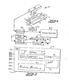
- Figure 1 is a schematic perspective view showing an optical reading system and the associated elements utilized in an image processing system according to the present invention;
- Figure 2 is a plan view illustrating a document with various fields of information thereon;
- Figure 3 is a schematic flow chart illustrating the sequence of operations carried out in the processing of image data obtained from the document in accordance with the present invention;
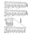
- Figure 4 is a block diagram schematic illustration of a series of control instructions for processing the data; and
- Figures 5 and 6 are block diagram schematic illustrations of the control instructions as they appear at various stages during the processing of successive fields of the document.
- Referring now more particularly to Figure 1, the
reference character 10 generally indicates an optical scanner, of known construction and operation, adapted for scanning and reading on a line-by-line basis information printed or written in selected areas or image fields of a document D. Theoptical scanner device 10 has a predetermined field of view extending widthwise of the document D in the form of a narrow line, and suitable means, such as drive rolls 11, are provided for advancing the document D through the field of view of the scanner device. As the document passes through the field of view of the scanner, it is scanned and read as a succession of closely arranged widthwise extending scan lines. The pattern of light and dark images present on the document D within the field of view of the scanning device is focused by alens 12 onto a photodetectingdevice 13. The photodetecting device converts the pattern of light and dark images into electrical signals defining a series of successively arranged picture elements or PEL's which collectively constitute the scan line. The signals are then processed by a suitable signal converter 14, such as an A to D converter, into a digital data signal describing each PEL of the scan line. - The
optical scanner 10 is also provided with means for counting the number of lines which have been used in scanning the document and for providing a data signal representing the sequence number of each scan line. This is schematically illustrated in Figure 1 by the line counter 15. As the document is successively scanned by theoptical scanner device 10, the image data for each scan line, obtained from the signal processor 14, together with the sequence number for each scan line, as determined by the line counter 15, is stored in a buffer 16. The buffer 16 may have a capacity for storing as many as several hundred scan lines of image data at any given time, with successive new scan lines being overwritten into locations previously occupied by earlier scan lines for which processing has been completed. - Image data for individual image fields of the document is extracted and processed under the control of the field cut function of the present invention, as schematically indicated at 17, with various operations being performed on the extracted data, such as for example character recognition, as indicated at 18, or image capture as indicated schematically at 19.
- Figure 2 illustrates in more detail a representative document D which may be processed in accordance with the present invention. The document illustrated contains six areas or image fields, identified by the
reference characters 1 to 6 respectively, which are of varying sizes and which are located at various locations on the document D. Additionally, the document contains a format field area, identified by the reference character F. While the image fields are represented in the drawing by boxes, it will be understood that the document need not necessarily contain printed boxes identifying the respective image fields, although in some instances this may be desirable. Contained within each of theimage fields 1 to 6 are various types of printed or handwritten information which is to be optically scanned and processed. Thus, for example, in the illustrative document D,field 1 contains a sense mark, such as a darkened box, at a predetermined location, whilefield 2 contains preprinted numbers.Field 3 contains two lines of printed alphabetic characters, whilefields Field 6 may, for example, contain a handwritten signature. - The numbers shown along the left hand side of the document represent the positions of the numbered scan lines for this document particularly in relation to the position of the image fields. Thus for example,
fields line 100 and end atscan line 200.Field 3 begins at scan line 250 and ends atscan line 600.Field 4, which is fully overlapped byfield 3, begins atscan line 300 and ends atscan line 400.Field 5 begins atscan line 550 and ends at scan line 1,000, whilefield 6 begins atscan line 800 and ends at scan line 1,200, thus partially overlappingfield 5. It is to be understood that the number of image fields, and their locations and sizes may vary, substantially without restriction, as to location, size or whether one image field overlaps another. - To facilitate processing different types of documents with differing image field arrangements, each document is uniquely identified by a format identification number, in the instance of the illustrated document, the format number being 124. This format number is located at a predetermined field location on the document where it can be recognized by character recognition logic.
- When a document is initially processed, the format identification field is scanned and the format identification number contained therein is recognized. This information enables the system to create, from prestored information, a particular chain of control instructions associated with that particular document format. This chain of control instructions is stored at predetermined memory addresses, and contains specific information for controlling the process of each field of the document. Each control instruction for each field includes information which defines the starting and ending locations of the field on the document, information designating the functions to be performed on the image data for the field, and pointers which identify the next field to be processed (i.e. a forward pointer) and the previous field (i.e. a rearward pointer). The processing system also provides a pointer to the first field in the chain of instructions and a pointer to the current field to which control instructions being used for processing relates.
- The operations which are carried out for each sequential scan line in accordance with the present invention will be understood more fully from the flow chart of Figure 3. As illustrated, prior to the processing of each sequential scan line, the current field pointer is set equal to the first field in the chain of instructions. Then, a comparison is made to determine whether the scan line being processed is in the current field. This is accomplished by comparing the value of the scan line with the value for the first scan line of the current field. If the current scan line number is less than the first scan line number for the field, this indicates that the line is not in any field. Processing of the scan line is terminated and the next scan line is read. If the scan line is greater than or equal to the scan number for the current field, then that scan is processed in accordance with the stored function definition for that field. Various processing functions may be carried out, such as, for example, character recognition, image capture, rotation, blankout, etc.
- After processing of the scan line for a given field, a determination is made whether the current field is completed. This may be accomplished, for example, by comparing the value of the current scan line number with the value for the last scan line of the current field. If the current scan line number is equal to the last scan line number for the field, then processing of that field is terminated. Alternatively, the particular processing function which is being carried out for the current field may determine that the current field is completed prior to reaching the last scan line for the field. For example, the character recognition function may determine that a character has been completely read and recognized and that no further characters may be expected to be found for the remaining scan lines of the current field. In this instance, the character recognition function itself may determine that the current field is completed.
- If the current field is not completed, the current pointer is set equal to the next field, and then, by reiterating the above described steps, a comparison is made to determine if the current scan line is also in that field, and processing proceeds accordingly.
- If it is determined that the current field is completed, the next step is to determine whether all fields have been completed, which will be the situation if the next field pointer of the current field is equal to zero and the last field pointer of the current field is equal to zero. If all fields are not completed, the field just completed is immediately removed from the chain so that processing of the remaining scan lines will bypass the control instructions for that field. Removal of a particular field from the chain is accomplished by changing the value of the forward pointer of the last (previous) field to the value of the forward pointer of the field to be deleted, and changing the value of the rearward pointer of the next active field to the value of the rearward pointer of the field to be deleted.
- When all fields have been completed, the next document may be processed.
- Referring now to Figure 4, the box indicated by the
reference character 29 represents a memory location containing the address of the current field, i.e. a "current field pointer". Thebox 30 represents a memory location containing a memory address or pointer for the starting or first field. The value of the starting field pointer at the beginning of processing is set equal to the memory address of the control instruction for the first field of the document, in thisinstance 1. The box indicated by thereference character 31 schematically represents a plurality of memory locations in which is stored the chain of control instructions for the illustrative document format number 124. The subboxes labelled "LAST" and "NEXT" represent the rearward and forward pointers respectively. The subboxes labelled "FORMAT" represent other control information or instructions for each respective field. The "FORMAT" information may, if desired, be stored in successive memory addresses in the chain ofcontrol instructions 31. Preferably however, and as illustrated in Figure 4, the pertinent information for each field is stored in a table at another location in memory. The box indicated by thereference character 32 schematically represents such a table in which there is stored for eachfield 1 to 6, the starting scan line number Y , the final scan line number Yf3 the starting PEL location of the field X s, the final PEL location of the field Xf, and a function controller OP which indicates the particular function to be carried out for that field. The table 32 may optionally include additional information as necessary or desirable. It will be understood that when the pertinent field information and instructions are stored in a static table 32, the subboxes labelled "FORMAT" in the chain ofcontrol instructions 31 comprise pointers to the appropriate memory addresses in the table 32. - Figure 4 illustrates how the chain of
control instructions 31 would appear at the beginning of processing of the document and during the scanning of each scan line from 1 to 200. As illustrated, the starting field pointer has a value of 1, the address of the control instruction for the first field to be processed. As each scan line is received, its scan line number is compared to the first scan line Y of the current field (field 1) identified by the pointer "Format 1". For each ofscan lines 1 to 99, the current scan line number will be less than the first scan line (100) of the current field (field 1) and processing terminates and the next scan line is read. Atscan line 100, since the current scan line is equal to or greater than 100, processing of that scan line takes place in accordance with the function definition for that field. Processing then continues to the next control instruction in the chain, that forfield 2. The current scan line number is again compared to the value of the first scan line for that field (field 2). Since the current scan line is equal to or greater than 100 (the value of the first scan line for field 2), that scan line is processed in accordance with the function definition forfield 2. Processing then continues for the next control instruction in the chain,field 3. The current scan line number is compared to the first scan line number for field 3 (250), and since the current scan line number is less than 250, the scan is not in that field, processing terminates and the next scan line is processed. Since the chain ofinstructions 31 is ordered in the sequence of the first appearance of scan lines, then, if the current scan line value is less than the value of the first scan line number of the current field, that scan line could not belong to any other field in the chain. Thus, unnecessary processing is avoided. - At the beginning of processing for
scan line 200, the startingfield pointer 30 is equal to 1, the address of the first field to be processed. - Processing of the scan line takes place in accordance with the function definition OP for
field 1. Upon completion of processing, the current scan line value is compared to the final scan line Y forfield 1, and it is determined thatfield 1 has been completed. Immediately,field 1 is removed from the chain. This is normally accomplished by referring to the rearward pointer of the current field to locate the previous field processed, and changing the value of the next field pointer in the previous field to the value of the next field pointer in the current field. In this instance, there is no previous field and removal offield 1 is performed by changing the value of the starting field pointer inlocation 30 from 1 to 2. Processing then continues for the next field in the chain,field 2. After the scan line has been processed in accordance with the function definition forfield 2, a similar test is made to determine iffield 2 has been completed. Sincefield 2 has also been completed,field 2 is removed from the chain by changing the startingfield pointer 30 to 3. - Thus, after
scan line 200 has been processed, the chain of instructions would appear as illustrated in Figure 5, and it will be seen that, as each scan line thereafter is processed, the sequential execution of the control instructions in the chain bypasses the control instructions forfields - Referring back to Figure 2, it will be seen that as the scan lines are sequentially processed, at some
point field 4 will be completed beforefield 3 is completed. This will occur, at the latest, upon processing ofscan line 400, although the particular function controller forfield 4 may determine thatfield 4 has been completed prior to reachingscan line 400. In either event, when it is determined thatfield 4 has been completed, the control instruction forfield 4 is immediately removed from the chain. This is accomplished by changing the NEXT value of the last (previous) field to the NEXT value of the field to be deleted. Additionally, the LAST value of the next active field in the chain is changed to the LAST value of the field to be deleted. Thus, as shown in Figure 6 the field to be deleted isfield 4, and the forward pointer (NEXT) offield 3 is changed to the NEXT value of field 4 (which is 5), and the rearward pointer (LAST) offield 5 is changed to the value of the LAST pointer of field 4 (which is 3). From then on,field 4 is effectively bypassed when the series of control instructions is executed for subsequent scan lines. - In a similar manner, the control instructions for the other fields in the document are removed from the chain. It will thus be seen how the series of control instructions dynamically changes as the successive scan lines of a document are read, with the control instructions for completed fields being promptly removed from the chain of instructions to optimize processing.
- In the drawings and specification, there has been set forth an exemplary embodiment of the invention. It should be understood that while specific terms are employed, they are used in a generic and descriptive sense only and not for purposes of limitation.
Claims (5)
characterised in that said processing means processes each set of data according to each set of control instructions in said chain in succession.
Applications Claiming Priority (2)
| Application Number | Priority Date | Filing Date | Title |
|---|---|---|---|
| US454582 | 1982-12-30 | ||
| US06/454,582 US4493108A (en) | 1982-12-30 | 1982-12-30 | Video image field cut processing |
Publications (3)
| Publication Number | Publication Date |
|---|---|
| EP0113086A2 true EP0113086A2 (en) | 1984-07-11 |
| EP0113086A3 EP0113086A3 (en) | 1986-10-15 |
| EP0113086B1 EP0113086B1 (en) | 1987-11-25 |
Family
ID=23805213
Family Applications (1)
| Application Number | Title | Priority Date | Filing Date |
|---|---|---|---|
| EP83112632A Expired EP0113086B1 (en) | 1982-12-30 | 1983-12-15 | Image data processing system |
Country Status (5)
| Country | Link |
|---|---|
| US (1) | US4493108A (en) |
| EP (1) | EP0113086B1 (en) |
| JP (1) | JPS59125476A (en) |
| CA (1) | CA1197004A (en) |
| DE (1) | DE3374724D1 (en) |
Cited By (7)
| Publication number | Priority date | Publication date | Assignee | Title |
|---|---|---|---|---|
| GB2162350A (en) * | 1984-06-28 | 1986-01-29 | Canon Kk | Image processing system |
| EP0217655A2 (en) * | 1985-09-27 | 1987-04-08 | Kabushiki Kaisha Toshiba | Method for reading a document and a document reading apparatus utilizing an image buffer |
| EP0374892A2 (en) * | 1988-12-20 | 1990-06-27 | Educational Testing Service | Image processing system |
| EP0415373A2 (en) * | 1989-08-31 | 1991-03-06 | Kabushiki Kaisha Toshiba | Document reader and reading processing method therefor |
| EP0442054A2 (en) * | 1990-02-12 | 1991-08-21 | International Business Machines Corporation | Method and apparatus for adaptive image processing |
| EP0504743A2 (en) * | 1991-03-19 | 1992-09-23 | T.A.S. & TRADING CO., Ltd. | Program creating method and method for automatic reading |
| US5369716A (en) * | 1989-08-31 | 1994-11-29 | Kabushiki Kaisha Toshiba | Document reader and reading processing method therefor |
Families Citing this family (12)
| Publication number | Priority date | Publication date | Assignee | Title |
|---|---|---|---|---|
| US4761818A (en) * | 1983-04-08 | 1988-08-02 | Canon Kabushiki Kaisha | Image processing apparatus |
| DE3442793A1 (en) * | 1983-11-25 | 1985-06-05 | Canon K.K., Tokio/Tokyo | IMAGE PROCESSING DEVICE |
| US4689824A (en) * | 1983-12-30 | 1987-08-25 | International Business Machines Corporation | Image rotation method |
| JPH07107694B2 (en) * | 1984-08-31 | 1995-11-15 | 株式会社日立製作所 | Document processor |
| US4821335A (en) * | 1985-04-05 | 1989-04-11 | Ricoh Company, Limited | Electronic blackboard |
| US4724307A (en) * | 1986-04-29 | 1988-02-09 | Gtech Corporation | Marked card reader |
| US4813077A (en) * | 1986-07-30 | 1989-03-14 | Scan-Optics, Inc. | Sales transaction record processing system and method |
| JPH0461730U (en) * | 1990-10-02 | 1992-05-27 | ||
| US5416308A (en) * | 1991-08-29 | 1995-05-16 | Video Lottery Technologies, Inc. | Transaction document reader |
| DE4330242A1 (en) * | 1993-09-07 | 1995-03-09 | Hell Ag Linotype | Method and device for the electronic assembly of printed sheets |
| US6357658B1 (en) | 1999-04-28 | 2002-03-19 | Peripheral Dynamics, Inc. | Apparatus and methods for scanning documents including OMR, bar-code, and image data |
| AU6336100A (en) * | 1999-06-22 | 2001-01-09 | Peripheral Dynamics Inc. | Apparatus and methods for image scanning of variable sized documents having variable orientations |
Citations (3)
| Publication number | Priority date | Publication date | Assignee | Title |
|---|---|---|---|---|
| US3571797A (en) * | 1969-06-02 | 1971-03-23 | Ibm | Area-format control in a character-recogniton system |
| US3618018A (en) * | 1969-06-02 | 1971-11-02 | Ibm | Unformatted scanning in a character-recognition system |
| JPS5743273A (en) * | 1980-08-28 | 1982-03-11 | Hitachi Ltd | Optical character reader |
Family Cites Families (4)
| Publication number | Priority date | Publication date | Assignee | Title |
|---|---|---|---|---|
| US29104A (en) * | 1860-07-10 | Improvement in plows | ||
| US3763467A (en) * | 1972-05-04 | 1973-10-02 | Ibm | Method and apparatus for reading documents |
| US4300123A (en) * | 1979-01-02 | 1981-11-10 | Westinghouse Electric Corp. | Optical reading system |
| JPS5654479A (en) * | 1979-10-12 | 1981-05-14 | Hitachi Ltd | Picture image data processor |
-
1982
- 1982-12-30 US US06/454,582 patent/US4493108A/en not_active Expired - Fee Related
-
1983
- 1983-09-19 JP JP58171445A patent/JPS59125476A/en active Granted
- 1983-11-14 CA CA000441048A patent/CA1197004A/en not_active Expired
- 1983-12-15 EP EP83112632A patent/EP0113086B1/en not_active Expired
- 1983-12-15 DE DE8383112632T patent/DE3374724D1/en not_active Expired
Patent Citations (3)
| Publication number | Priority date | Publication date | Assignee | Title |
|---|---|---|---|---|
| US3571797A (en) * | 1969-06-02 | 1971-03-23 | Ibm | Area-format control in a character-recogniton system |
| US3618018A (en) * | 1969-06-02 | 1971-11-02 | Ibm | Unformatted scanning in a character-recognition system |
| JPS5743273A (en) * | 1980-08-28 | 1982-03-11 | Hitachi Ltd | Optical character reader |
Non-Patent Citations (2)
| Title |
|---|
| IBM TECHNICAL DISCLOSURE BULLETIN, vol. 15, no. 8, January 1973, pages 2443-2444, New York, US; L.S. HEIM et al.: "Collection of noncoded data fields on an optical character recognition machine" * |
| PATENTS ABSTRACTS OF JAPAN, vol. 6, no. 112 (P-124)[990], 23rd June 1982; & JP - A - 57 43 273 (HITACHI SEISAKUSHO K.K.) 11-03-1982 * |
Cited By (14)
| Publication number | Priority date | Publication date | Assignee | Title |
|---|---|---|---|---|
| GB2162350A (en) * | 1984-06-28 | 1986-01-29 | Canon Kk | Image processing system |
| EP0217655A2 (en) * | 1985-09-27 | 1987-04-08 | Kabushiki Kaisha Toshiba | Method for reading a document and a document reading apparatus utilizing an image buffer |
| EP0217655A3 (en) * | 1985-09-27 | 1989-11-29 | Kabushiki Kaisha Toshiba | Method for reading a document and a document reading apparatus utilizing an image buffer |
| EP0374892A3 (en) * | 1988-12-20 | 1992-05-20 | Educational Testing Service | Image processing system |
| EP0374892A2 (en) * | 1988-12-20 | 1990-06-27 | Educational Testing Service | Image processing system |
| EP0415373A2 (en) * | 1989-08-31 | 1991-03-06 | Kabushiki Kaisha Toshiba | Document reader and reading processing method therefor |
| EP0415373A3 (en) * | 1989-08-31 | 1992-08-26 | Kabushiki Kaisha Toshiba | Document reader and reading processing method therefor |
| US5369716A (en) * | 1989-08-31 | 1994-11-29 | Kabushiki Kaisha Toshiba | Document reader and reading processing method therefor |
| EP0442054A2 (en) * | 1990-02-12 | 1991-08-21 | International Business Machines Corporation | Method and apparatus for adaptive image processing |
| EP0442054A3 (en) * | 1990-02-12 | 1992-12-16 | International Business Machines Corporation | Method and apparatus for adaptive image processing |
| EP0734146A2 (en) * | 1990-02-12 | 1996-09-25 | International Business Machines Corporation | Method and apparatus for adaptive image processing |
| EP0734146A3 (en) * | 1990-02-12 | 1997-01-29 | Ibm | Method and apparatus for adaptive image processing |
| EP0504743A2 (en) * | 1991-03-19 | 1992-09-23 | T.A.S. & TRADING CO., Ltd. | Program creating method and method for automatic reading |
| EP0504743A3 (en) * | 1991-03-19 | 1994-01-05 | T A S & Trading Co Ltd |
Also Published As
| Publication number | Publication date |
|---|---|
| US4493108A (en) | 1985-01-08 |
| JPS645351B2 (en) | 1989-01-30 |
| JPS59125476A (en) | 1984-07-19 |
| CA1197004A (en) | 1985-11-19 |
| EP0113086A3 (en) | 1986-10-15 |
| EP0113086B1 (en) | 1987-11-25 |
| DE3374724D1 (en) | 1988-01-07 |
Similar Documents
| Publication | Publication Date | Title |
|---|---|---|
| EP0113086B1 (en) | Image data processing system | |
| EP0372762B1 (en) | Minutia data extraction in fingerprint identification | |
| US4856074A (en) | Region recognizing device | |
| US5048107A (en) | Table region identification method | |
| US5260805A (en) | Process for identifying programming conflicts in electronic printing systems | |
| JP3048330B2 (en) | Apparatus and method for extracting articles from documents | |
| EP0920189A3 (en) | Image processing apparatus | |
| US4700402A (en) | Input method for graphic pattern data | |
| US7034879B2 (en) | Imaging device for ID card preparation and associated method | |
| US5157666A (en) | Disk timing diagnostic | |
| JPH06319023A (en) | Control method for copy image output order | |
| JP2906608B2 (en) | Optical character reader | |
| JP2001256491A (en) | Device and method for cutting picture and recording medium for recording its program | |
| JPS5920147B2 (en) | Information storage method and device | |
| JP2683711B2 (en) | How to recognize / correct character / symbol data | |
| JP2790276B2 (en) | Character reader | |
| JP3747602B2 (en) | Image processing method and image processing apparatus | |
| JPS596419B2 (en) | Character extraction method | |
| JP2665226B2 (en) | Character recognition device | |
| JP2504373B2 (en) | Character recognition device | |
| JPH0660217A (en) | Optical character reader | |
| EP0428795A1 (en) | Binary image thinning and feature extracting method and processing device thereof | |
| JPS61134883A (en) | Correction system in character reader | |
| JPH0528314A (en) | Optical character reader | |
| JPS62210591A (en) | Optical character reader |
Legal Events
| Date | Code | Title | Description |
|---|---|---|---|
| PUAI | Public reference made under article 153(3) epc to a published international application that has entered the european phase |
Free format text: ORIGINAL CODE: 0009012 |
|
| AK | Designated contracting states |
Designated state(s): CH DE FR GB IT LI NL |
|
| 17P | Request for examination filed |
Effective date: 19841029 |
|
| PUAL | Search report despatched |
Free format text: ORIGINAL CODE: 0009013 |
|
| AK | Designated contracting states |
Kind code of ref document: A3 Designated state(s): CH DE FR GB IT LI NL |
|
| 17Q | First examination report despatched |
Effective date: 19870204 |
|
| GRAA | (expected) grant |
Free format text: ORIGINAL CODE: 0009210 |
|
| AK | Designated contracting states |
Kind code of ref document: B1 Designated state(s): CH DE FR GB IT LI NL |
|
| REF | Corresponds to: |
Ref document number: 3374724 Country of ref document: DE Date of ref document: 19880107 |
|
| ET | Fr: translation filed | ||
| ITF | It: translation for a ep patent filed |
Owner name: IBM - DR. ARRABITO MICHELANGELO |
|
| PLBE | No opposition filed within time limit |
Free format text: ORIGINAL CODE: 0009261 |
|
| STAA | Information on the status of an ep patent application or granted ep patent |
Free format text: STATUS: NO OPPOSITION FILED WITHIN TIME LIMIT |
|
| 26N | No opposition filed | ||
| ITTA | It: last paid annual fee | ||
| PGFP | Annual fee paid to national office [announced via postgrant information from national office to epo] |
Ref country code: CH Payment date: 19950321 Year of fee payment: 12 |
|
| PGFP | Annual fee paid to national office [announced via postgrant information from national office to epo] |
Ref country code: GB Payment date: 19951127 Year of fee payment: 13 |
|
| PGFP | Annual fee paid to national office [announced via postgrant information from national office to epo] |
Ref country code: FR Payment date: 19951128 Year of fee payment: 13 |
|
| PGFP | Annual fee paid to national office [announced via postgrant information from national office to epo] |
Ref country code: DE Payment date: 19951229 Year of fee payment: 13 |
|
| PGFP | Annual fee paid to national office [announced via postgrant information from national office to epo] |
Ref country code: NL Payment date: 19951230 Year of fee payment: 13 |
|
| PG25 | Lapsed in a contracting state [announced via postgrant information from national office to epo] |
Ref country code: LI Effective date: 19951231 Ref country code: CH Effective date: 19951231 |
|
| REG | Reference to a national code |
Ref country code: CH Ref legal event code: PL |
|
| PG25 | Lapsed in a contracting state [announced via postgrant information from national office to epo] |
Ref country code: GB Effective date: 19961215 |
|
| PG25 | Lapsed in a contracting state [announced via postgrant information from national office to epo] |
Ref country code: NL Effective date: 19970701 |
|
| GBPC | Gb: european patent ceased through non-payment of renewal fee |
Effective date: 19961215 |
|
| PG25 | Lapsed in a contracting state [announced via postgrant information from national office to epo] |
Ref country code: FR Effective date: 19970829 |
|
| NLV4 | Nl: lapsed or anulled due to non-payment of the annual fee |
Effective date: 19970701 |
|
| PG25 | Lapsed in a contracting state [announced via postgrant information from national office to epo] |
Ref country code: DE Effective date: 19970902 |
|
| REG | Reference to a national code |
Ref country code: FR Ref legal event code: ST |