EP0113425A1 - Method of and apparatus for establishing the characteristics of a prerecorded two-channel audio program - Google Patents
Method of and apparatus for establishing the characteristics of a prerecorded two-channel audio program Download PDFInfo
- Publication number
- EP0113425A1 EP0113425A1 EP83111951A EP83111951A EP0113425A1 EP 0113425 A1 EP0113425 A1 EP 0113425A1 EP 83111951 A EP83111951 A EP 83111951A EP 83111951 A EP83111951 A EP 83111951A EP 0113425 A1 EP0113425 A1 EP 0113425A1
- Authority
- EP
- European Patent Office
- Prior art keywords
- audio
- video
- channels
- signal
- test
- Prior art date
- Legal status (The legal status is an assumption and is not a legal conclusion. Google has not performed a legal analysis and makes no representation as to the accuracy of the status listed.)
- Granted
Links
Images


Classifications
-
- G—PHYSICS
- G11—INFORMATION STORAGE
- G11B—INFORMATION STORAGE BASED ON RELATIVE MOVEMENT BETWEEN RECORD CARRIER AND TRANSDUCER
- G11B5/00—Recording by magnetisation or demagnetisation of a record carrier; Reproducing by magnetic means; Record carriers therefor
- G11B5/84—Processes or apparatus specially adapted for manufacturing record carriers
-
- G—PHYSICS
- G11—INFORMATION STORAGE
- G11B—INFORMATION STORAGE BASED ON RELATIVE MOVEMENT BETWEEN RECORD CARRIER AND TRANSDUCER
- G11B20/00—Signal processing not specific to the method of recording or reproducing; Circuits therefor
- G11B20/02—Analogue recording or reproducing
- G11B20/025—Error detection or correction
-
- G—PHYSICS
- G11—INFORMATION STORAGE
- G11B—INFORMATION STORAGE BASED ON RELATIVE MOVEMENT BETWEEN RECORD CARRIER AND TRANSDUCER
- G11B20/00—Signal processing not specific to the method of recording or reproducing; Circuits therefor
- G11B20/10—Digital recording or reproducing
- G11B20/18—Error detection or correction; Testing, e.g. of drop-outs
- G11B20/1816—Testing
- G11B20/182—Testing using test patterns
-
- G—PHYSICS
- G11—INFORMATION STORAGE
- G11B—INFORMATION STORAGE BASED ON RELATIVE MOVEMENT BETWEEN RECORD CARRIER AND TRANSDUCER
- G11B27/00—Editing; Indexing; Addressing; Timing or synchronising; Monitoring; Measuring tape travel
- G11B27/02—Editing, e.g. varying the order of information signals recorded on, or reproduced from, record carriers
- G11B27/022—Electronic editing of analogue information signals, e.g. audio or video signals
- G11B27/024—Electronic editing of analogue information signals, e.g. audio or video signals on tapes
-
- G—PHYSICS
- G11—INFORMATION STORAGE
- G11B—INFORMATION STORAGE BASED ON RELATIVE MOVEMENT BETWEEN RECORD CARRIER AND TRANSDUCER
- G11B27/00—Editing; Indexing; Addressing; Timing or synchronising; Monitoring; Measuring tape travel
- G11B27/02—Editing, e.g. varying the order of information signals recorded on, or reproduced from, record carriers
- G11B27/022—Electronic editing of analogue information signals, e.g. audio or video signals
- G11B27/028—Electronic editing of analogue information signals, e.g. audio or video signals with computer assistance
-
- G—PHYSICS
- G11—INFORMATION STORAGE
- G11B—INFORMATION STORAGE BASED ON RELATIVE MOVEMENT BETWEEN RECORD CARRIER AND TRANSDUCER
- G11B27/00—Editing; Indexing; Addressing; Timing or synchronising; Monitoring; Measuring tape travel
- G11B27/36—Monitoring, i.e. supervising the progress of recording or reproducing
-
- H—ELECTRICITY
- H04—ELECTRIC COMMUNICATION TECHNIQUE
- H04N—PICTORIAL COMMUNICATION, e.g. TELEVISION
- H04N17/00—Diagnosis, testing or measuring for television systems or their details
- H04N17/04—Diagnosis, testing or measuring for television systems or their details for receivers
-
- H—ELECTRICITY
- H04—ELECTRIC COMMUNICATION TECHNIQUE
- H04N—PICTORIAL COMMUNICATION, e.g. TELEVISION
- H04N17/00—Diagnosis, testing or measuring for television systems or their details
- H04N17/06—Diagnosis, testing or measuring for television systems or their details for recorders
-
- G—PHYSICS
- G11—INFORMATION STORAGE
- G11B—INFORMATION STORAGE BASED ON RELATIVE MOVEMENT BETWEEN RECORD CARRIER AND TRANSDUCER
- G11B2220/00—Record carriers by type
- G11B2220/20—Disc-shaped record carriers
-
- G—PHYSICS
- G11—INFORMATION STORAGE
- G11B—INFORMATION STORAGE BASED ON RELATIVE MOVEMENT BETWEEN RECORD CARRIER AND TRANSDUCER
- G11B2220/00—Record carriers by type
- G11B2220/90—Tape-like record carriers
Definitions
- This invention relates to the evaluation of the quality of audio and/or video transfer characteristics of a device upon which, or through which, audio and/or video information is contained, or passes, respectively.
- the invention concerns both method and apparatus for evaluating the quality of information transfer in the recording and playing back of a recording medium or in the transferring of audio and/or video information through an information handling device referred to herein as a "throughput" device.
- this invention can be effective in the evaluation of a recording medium per se, of the quality of transfer of information contained on one recording medium to a similar or another recording medium, or of a throughput electronic apparatus such as an amplifier or other signal processing apparatus through which audio and/or video information passes.
- a large number of audio and video measurements are performed on the unit under test electronically to determine out-of-tolerance conditions of the unit as a basis for passing or rejecting the unit in a production line.
- a unit evaluation method and means is described which will eliminate subjectivity and provide consistency in the quality level of device testing.
- unit evaluation is accomplished by establishing an input signal of known content, measuring selected parameters of selected parts of the input signal, feeding the input signal to the unit under test, measuring the parameters of parts of the output signal from the unit under test corresponding to the same selected parts of the input signal, and comparing the selected parameters of the input signal with the corresponding parameters of the output signal.
- unit in the phrase “unit evaluation” includes tapes, discs, audio records, electronic storage, various electronic circuits ranging from simple integrated circuits or printed circuit boards to macrosize amplifier or other complex information handling equipment.
- signature Another term used through this application is “signature”.
- signature has been used in the prior art to designate a parameter listing against which devices being tested are compared.
- the term "signature” as used in this application has a degree of identity or “personality” of the unit under test, insofar as the “signature” is comprised of a multiplicity of test parameters, each parameter having limits within which comparable measurements of the unit under test must fall. Accordingly, the "signature” as used with this invention is a practical, as opposed to theoritical, model against which all further units are compared.
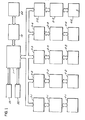
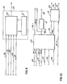
- Figure 1 shows a complete audio/video quality monitoring system utilizing a central controller 1 and a plurality of terminals each comprising an interface subsystem 3, an audio/video test subsystem 2, and the unit under test 4 connected to the audio/video test subsystem 2.
- the peripheral equipment associated with the central controller 1 comprises a memory unit 13, a keyboard 70, a data evaluation subsystem 19, and a data readout device or devices 64.
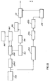
- Figure 3 shows a greatly expanded version of the arrangement shown in Figure 1 with central controller 1 and its associated peripheral equipment connected with only a single interface subsystem 3, audio test subsystem 5, video test subsystem 7, and unit under test 4.
- the unit under test 4 has been treated as strictly a player-type unit capable of reproducing audio and video signals from a prerecorded tape or disc.
- the phrase "unit under test”, however, carries with it, for the purposes of this application, a more complex arrangement comprised of a tape recorder/player 11, a disc player 9, and an audio and video selector 53 as shown within the unit under test block 4 in Figure 3.
- the disc player is capable of outputting both video and audio signals to the selector 53 on lines 147 and 151, respectively.
- the tape recorder/player 11 outputs video on line 149, and audio on line 153.
- the audio lines 151 and 153 carry two lines of audio for the purposes of accommodating a stereophonic or two channel signal.
- Operation control i.e., stop, play, reverse, fast forward, rewind, etc.
- operation control 117 in interface substystem 3 via cable 133 shown in Figure 3 as a single line for simplifying the drawing.
- Operation control is also effective to select either audio channel, or both, and video from either the disc player 9 or tape recorder/player 11. Audio and video are thus outputted on lines 58 and 118, respectively, leaving the audio and video selector 53.
- Tape position is outputted on the data channel output line of the tape player-11, and audio test tones are applied to the tape by tape recorder 11 as will be discussed in connection with more detailed figures later.
- the first step in the process is to transfer the customer's program from the master tape to a submaster or pre-mastering tape. Simultaneously with the transferring of the video portion of the program to the pre-mastering tape, appropriate video test signals are inserted on lines 19 and 20 of the vertical interval. A timed sequence of audio test signals is recorded at a predetermined location on the lead-in and lead-out portions of the pre-mastering tape. The signals will be used to analyze the audio quality of the signals recorded on the tape and Q n the disc to be made from the tape. Details of the lead-in and lead-out audio testing will now be discussed.
- the data channel from the tape player 11 is outputted on line 34 and is sent to time code selector 51, a second input of which is a time code signal from time code register 116 as set up by the keyboard 70 via central controller 1.
- the operator thus rewinds the tape on recorder 11 to a position upstream of the start position for the test tones and sets the tape recorder into a recording mode through actuation of operation control 117 over line 133.
- the time code selector 51 sends an output compare signal to the audio controller 21 which then initiates, over line 30, test tone generator 49 to apply test tones to both channels 1 and 2 of tape recorder 11.
- the operator performs a high speed tape wind to a point corresponding to the end of the active program and enters a second beginning point for the test tones to occur, during lead-out of the tape, beginning at least 150 frames after the program end.
- a match is again detected by time code selector 51 at at least 150 frames after the program end, the tape recorder is put into record mode, and the test tone generator 49 is enabled by audio controller 21 to deposit test tones on channels 1 and 2 of the tape recorded by tape recorder 11.
- the present invention can be utilized to insert audio test tones in between isolated program segments, as well as during lead-in and lead-out locations.
- analyzing the signal transferring characteristics of a signal processing unit can be accomplished by establishing an input signal of known content, measuring selected parameters of selected parts of such input signal, feeding that input signal to the signal processing unit, measuring the parameters of parts of the output signal from the signal processing unit corresponding to the similar selected parts of the input signal, and comparing the selected parameters of the input signal with the corresponding parameters of the output signal.
- the tolerance limits for the measurement of parameters of the output signal are derived as deviation levels from the measurement of the corresponding parameters of the selected parts of the input signal.
- the method involves establishing an input signal of known content, measuring selected parameters of selected parts of the input signal, storing the input measurement results to define a stored signature of the input signal comprising the selected parameters of selected parts of the input signal, feeding the input signal to the processing unit, measuring the parameters of parts of the output signal from the signal processing unit corresponding to selected parts of the input signal, and subsequently comparing the parameters of the output signal with the corresponding input signature parameters.
- the method of analyzing just described can be supplemented by a further step in the evaluation process. That is, before comparing the output signal measurement with the stored selected input signature parameters, the measurements of the output signal can also be stored to define a stored signature of the output signal comprising selected parameters of selected parts of the output signal, and the comparing step would then comprise comparing the stored output signal signature with the stored input signal signature.
- a 6734 head tone is recorded and retrieved from only one channel (e.g., channel 2 of a two channel audio program). This head tone identifies the beginning of the audio test tone sequence, and the audio on line 58 ( Figure 3) or line 58-2 ( Figure 4) from the audio and video selector 53 is routed to the 6734 tone detector 41. The output of 6734 detector 41 is routed over line 82 to the audio controller 21 which provides, under internal process control, all of the timing functions for the remainder of the audio test subsystem 5.
- Audio controller 1 is enabled preparatory to the system recognizing the 6734 tone burst by the operator, through keyboard 70, central controller 1, and interface subsystem 3 by the sending of a request to the audio subsystem to load its internal acquisition program and to activate the audio test subsystem.
- a SMPTE start code is entered by the tape operator to indicate the start of active program as expressed in hours and minutes.
- a SMPTE end code as entered by the tape operator indicates the end of active program as expressed hours and minutes.
- the central controller then instructs the operator to rewind and start the tape or disc from the beginning.
- the central controller sends the SMPTE start code minus 25 seconds to the interface subsystem 3 and loads it into time code registers 116.
- time code selector 51 alerts the audio controller 21 over line 76 that lead-in of the tape or disc is being read.
- detection of the 6734 tone burst initiates the action of audio controller 21 to perform its timing sequences for the various analyzing functions of the audio test subsystem over line 30.
- One of the output control signals over line 30 is a control and trigger signal routed to the multiprogrammer 23.
- multiprogrammer 23 Upon receipt of the control and trigger signal, multiprogrammer 23 digitizes the segmented audio test tones on line 58, stores the digitized version of the test tones in memory, and under control of the audio controller 21, converts a selected segment of the audio test tones to a continuous analog representation and sends such representation over line 46 to audio signal analyzer 25 for general analysis, and to audio spectrum analyzer 27 for spectrum analysis of the lead-in and lead-out test tones.
- Direct audio on line 58 from the audio/video selector 53 is routed to an active program spectrum analyzer 43 and a mono/non-mono signal check 62, the former performing spectrum analysis of selected portions of the active program material, and the latter making a determination as to whether or not the two audio signals on the two audio channels of the playback audio are substantially the same or different, thereby indicating that the audio portion of the program is either monophonic or non-monophonic.
- the term "stereo" is not used in describing the function of the signal check block 62, since the invention is equally suited for analyzing audio signals on the two channels in the form of monophonic, stereophonic, or totally separate audio tracks.
- each of the signal analysis blocks of the audio test subsystem are routed to a data evaluation subsystem 19 which, under instructions from the operator through central controller 1 compares the audio analysis results with standards, i.e., performs a signature comparison, and outputs the results of the evaluation onto a printer 15 or visual display 17.
- the video from audio and video selector 53 overline 118 is routed to the video test subsystem 7, the video signal being converted from analog to digital form by A/D converter 123, the digitized version being stored in digital memory 124 and selectively processed or analyzed in video processor 125.
- the output of video processor 125 is thus a video "signature" of the recovered video signal, is outputted over line 126 to the data evaluation subsystem 19, and the thus obtained output "signature” is compared with a stored signature in the data evaluation subsystem 19, the results of which is printed on printer 15 and/or displayed at display station 17.
- Program start and end signals on line 76 and evaluate start on line 78 all from code or frame number selector 51 enable audio controller 21 to initiate and periodically check active audio as a result of decoding frame time codes from the vertical interval of the video received from the audio/video selector 53 on line 118.
- Figure 5 shows a schematic representation of a length of video tape containing a lead-in portion, a lead-out portion, and a program material portion sandwiched therebetween.
- the beginning of the tape 55 has a lead-in portion 57, a test tone zone 59 on the lead-in portion, and a guard portion 65 of lead-in, all followed by the program material portion 67.
- the test tone zone 59 on lead-in is comprised of two tracks of audio test tones, track 1 being represented by numeral 61 and track 2 by numeral 63.
- a lead-out guard portion 65 precedes test tone zone 59 comprised of audio track 1 shown at 61, audio track 2 shown at 63, and lead-out portions 57 extending to the end of the tape.
- the dotted line at 66 represents a control track for use in synchronizing the tape drive of the tape recorder upon playback, among other things, and a cue track 68 upon which can be recorded a variety of signals, including tim code frame numbers, editing data, additional audio, etc.
- a segmented signal train of appropriate test signals is recorded on both the lead-in and lead-out areas of the pre-mastering tape.
- audio test tones are recorded on both audio channels of the tape and occupy 12 vertical frame times in corresponding areas on both of the audio channels as represented by the vertical dotted lines in Figure 6.
- Preceding the 12 frames of test tones, on channel 2 is the 6734 test tone location signal.
- the top half of Figure 6 schematically shows the two audio channels 61 and 63 with a literal designation of the type of signal contained in each frame time period of each audio channel.
- the bottom half of Figure 6 is a drawing of the approximate waveforms of the signals identified in the upper half of Figure 6.
- phase amplitude, signal-to-noise, and harmonic distortion measurements are taken. Since the two channels contain, for the durations of segments 2 and 3, one kilohertz on one channel simultaneously with DC (i.e., no signal) on the other channel, cross talk measurements from one channel to the other are taken during segments 2 and 3.
- each channel contains a DC level, and thus noise level measurements are taken during these time slots.
- a prescribed summation of 60HZ and 7KHZ tones is contained on segments 5 and 6, and when analyzed with appropriate test equipment indicate the intermodulation distortion level through the recording and playback process.
- segments 8-12 contain audio tones continuously sweeping through a wide range of frequencies, i.e., from 20HZ to 20KHZ, and the analysis of the recovered test tones in this area reflect the frequency response of the transfer characteristics.
- test tone recording process upon command from the keyboard operator, an enabling signal over line 18 is routed to audio controller 21.
- the tape is rewound and put into play condition, whereupon the .SMPTE code derived by the central controller 1 is loaded into lead-in location register 87 and sent over line 86 to comparator 91.
- a position detector 85 reads the SMPTE time code off the data channel tape recorder 11 and sends the detected position information over line 84 also to comparator 91.
- controller 21 After enabling of the audio controller 21, the controller 21 interrogates comparator 91 for detection of correspondence between the present position detected by position detector 85 and the predetermined point at which lead-in test tone signals are to be applied, the latter location information taken from lead-in location register 87. When a'comparison is found, an output of the comparator 91 over line 28 initiates the subsequent multiplexing action under control of audio controller 21.
- controller 21, over line 72 selectively and at a video vertical repetition rate enables one or two of the function generators feeding multiplexer 71. Multiplexer 71 then sums the outputs of the selected function generators, and outputs the desired combinations shown in Figure 6 over lines 76 and 78 to be routed to the input channels 1 and 2 of tape recorder 11.
- audio controller 21 Simultaneously with detection of the compare signal on line 28, audio controller 21 outputs a record enable signal on line 80 to tape recorder 11 in order to change the recorder from the play to the record mode so that the audio test tones will be deposited, in the fashion shown in Figure 6, on the separate audio channels.
- Control of forward, reverse, play, and stop motions of the tape recorder 11 are effectuated under control of audio controller 21 over the lines in cable 133.
- Not shown in Figure 7 are communication links between the central controller 1, interface subsystem 3, and the audio test subsystem 5 which communicate the operator's keyboard commands to the audio controller for effectuating the various motion functions of the tape recorder 11.
- These are typical control communication paths which can be inplemented in a variety of known ways.
- FIG. 8 A general block diagram of the audio analysis logic is shown in Figure 8.
- both a disc player 9 and a tape recorder/player 11 are shown connected to an audio selector 53 (the audio portion of audio and video selector 53) the two audio outputs of disc player 9 being carried by line 32, while the two channels out of the tape player 11 are carried by line 16.
- Channels 1 and 2 audio out of the audio selector 53 are carried on lines 58-1 (channel 1) and 58-2 (channel 2). It will be noted that only channel 2 audio is sent to the 6734 detector 41, consistent with the waveforms shown in Figure 6.
- the audio on line 58-1 enters A/D converter 37, is digitized thereby and sent over line 36 to the digitized test tones memory 33 for storage.
- a control and trigger signal on line 30 is effective to cause recirculate control 99-1 to recirculate a selected test tone segment in the digitized memory 33 and output that selected tone segment in a continuous manner over line 38 to D/A converter 39.
- the continuous representation of the selected test tone is then routed over line 46 to the audio signal analyzer 25 and lead-in/lead-out spectrum analyzer 27 as described briefly earlier.
- the outputs of the two analyzers 25 and 27 are routed over lines 48 and 50 to audio analysis memory 47.
- the memory unit 45 thereof has information written into it by memory write gates 44 which receive outputs from multiplexer 42 in a timed manner under control of audio controller 21 over line 30.
- comparator 95 makes a comparison of the time code contained in the video information of the active program material so as to identify program start, program end, and various points along the program material content at which active audio and/or video tests are to be carried out.
- comparator 91 since there is no video contained in the lead-in and lead-out portions of a tape or disc, comparator 91 must rely upon SMPTE time code detection from either the data channel out or audio out signals of the tape and disc player.
- the audio test subsystem proceeds to analyze active audio program material at predetermined time intervals during the active programming.
- Comparator 95 is thus provided with present position data from the vertical interval of the video signal, and location register 109, when matched with present position, outputs a program start signal to the audio controller 21 to ready the audio controller for subsequent active program analysis control.
- location register 111 will have a position location match with present position from position detector 85, and comparator 95 will output an evaluate start signal over line 78 to audio controller 21. Control then of two additional audio analysis functions of the audio test subsystem commences under control of audio controller 21 over the control line generally designated at 30 in Figure 8.
- Analyzer 43 contains two analyzer arrays, one for each of the audio channels. Since the audio to be analyzed during active program material is continuous, it is not necessary to digitize and recirculate audio segments in the multiprogrammer 23 as was necessary with the short segment deration test tones of the lead-in and lead-out portions of the tape or disc. Accordingly, the audio entering spectrum analyzer 43 is selected audio direct from the playback devices. Both arrays 113 and 115 of the spectrum analyzer 43 operate in identical fashion, i.e., a 45 second audio waveform from each audio channel is acquired and transformed into two frequency spectrum of 128 separate frequency points for each channel.
- Point spacing is in 200HZ increments, and each value analyzed at each point is expressed in decibels.
- the frequency spectrum for each sample represents a unique audio "print”, and the 128 points for each channel have their values contained on lines 56 and 60, respectively, and these values are multiplexed with the other analyzer signals in multiplexer 42, and ultimately stored in memory unit 45.
- a signal on line 4 54 indicating whether or not the audio portion of the program is monophonic or non-monophonic.
- the signal is developed in the mono/non-mono signal check block 62.
- Channel 1 and channel 2 audio are received by block 62 over lines 58-1 and 58-2, respectively, these two signals being compared with each other in amplitude comparator 105.
- Mono/non-mono testing is performed at intervals throughout the active programs areas of the tape or disc. Each test consists of 65,536 measurements, the measurements being spaced one millisecond apart.
- Block 62 illustrates a preferred embodiment of the mono/non-mono check in which the amplitudes of the two audio channels are continuously compared in comparator 105 with the difference between the two audio channels being outputed on line 84. If the amplitudes are within 5% of each other, threshold detector 107 does not react to the signal on line 84, there is no output on line 86, and a 1 KHZ clock 103 is applied over line 88 to the mono/non-mono counter 101. Without an input on line 86, i.e. the amplitudes of the audio on both audio channels are within 5% of one another, counter 101 is incremented by 1 count.
- counter 101 is again incremented if the amplitudes are again within 5% of one another. This procedure continues in like manner until the measured amplitudes between the two audio channels are greater than 5% in difference, at which time threshold detector 107 outputs a step waveform on line 86 to inhibit counter 101 from incrementing one count.
- the accumulated count is sent over line 54 to multiplexer 42 and stored in memory unit 45 by memory write gate 44 to become a part of the "signature" for the unit tested.
- the greater the number count on line 54 i.e. the closer the accumulated count is to 65,536, the more definite it is that the two audio signals on the two audio channels are the same, i.e. the audio program is monophonic.
- An alternate implementation of the mono/non-mono check block 62 is represented by the dotted line 88' from 1KHZ clock 103 to amplitude comparator 105.
- the amplitude of the audio on the two channels 58-1 and 58-2 are not compared continuously, but rather are compared under the gating action of the 1KHZ clock, that is, a comparison is made every millisecond.
- Comparator 105 is then arranged such that, when the amplitudes of the signals of the two audio input lines 58-1 and 58-2 are within 5% of one another, an output pulse is routed to threshold detector 107 along line 84.
- threshold detector 107 is then a step when the amplitudes on the two audio channels are within 5% of one another and DC when the amplitudes are greater than 5% of one another. Since comparator 105 is clocked at a 1KHZ rate, the maximum frequency step signal out of threshold detector 107 is also 1KHZ, and when a stereophonic or non-monophonic program is being and counter 101 is incremented fewer times.
- this embodiment of the mono/non-mono signal check merely counts the number of times that the amplitudes of the samples from the two audio channels are within a prescribed percentage tolerance of one another (5%) to provide information regarding whether or not the signals on the two channels are substantially similar in informational content.
- FIG. 9 is a more detailed diagram of the audio controller 21, showing that is basically comprised of a processor 29 and read-only memory 31.
- Read-only memory 31 can take on any of various forms of memory such as tape cassette, hard wired or burned in micro chips, and the like.
- the purpose of the memory is to set up the control functions of the audio controller in a prescribed manner upon enablement by the central controller 1 and/or interface subsystem and line 18, the processor instructs the read-only memory 31 to prepare the processor 29 for outputting its control logic on line 30, (representing a plurality of actual signal lines) depending upon subsequent signals received by processor 29.
- the lead-in and lead-out identification signal can, in a simplified system be comprised of a non-standard frequency such as 6734 HZ lasting the time of one picture frame preceding the sequence of test tones of the lead-in and lead-out portions of the tape or disc.
- a better identification signal is preferably a coded form for a sequence of numerical digits such as 6, 7, 3, and 4.
- the code is a self-clocking digital representation of the number series 6734 which is chosen so as to remove from chance (for all practical purposes) the possibility that any other randomly recovered signal from tape or disc would falsely appear to be the identification signal.
- the coded digits are represented in binary by switching between two square wave source tones, a 1 KHZ tone and a 2.5 KHZ tone, according to 1 and 0 binary states, respectively.
- the transitions attributed to the 1 KHZ tone are interpreted as logital l's, while the transitions attributed to the 2.5 KHZ tone are interpreted as logical O's.
- detector 41 Upon detection of a proper combination of l's and O's making up the binary representations of 6, 7, 3, and 4, detector 41 outputs a "match" signal to indicate that the series of lead-in and lead-out test signals follow.
- video signals are utilized in the audio test subsystem for the purpose of determining when active audio is to be analyzed, and such information is derived from the frame number codes in the vertical interval of the video signal. Accordingly, the video from disc player on line 147 and the video from tape player on line 149 are routed to selector 53, and _ depending upon which program is to be analyzed, disc or tape, an output video signal on line 118 is rounted to frame number selector 51.
- a "program start” signal is generated on line 76 upon coincidence of the first frame of the active video program with the predetermined frame code number, and subsequently an "evaluate start” signal is generated on line 78 upon coincidence of the predetermined points of analyzing the active audio portion of the program with predeatermined frame codes. Since audio analyzing is accomplished in a rather short period of time as compared with the length of most programs (e.g. 45 seconds for spectrum analysis and 65.5 seconds for mono/non-mono check), a number of predetermined frame codes on line 18-2 received by selector 51 will result in a plurality of spaced "evaluate start” signals on line 78.
- multiprogrammer 23 Details of the multiprogrammer 23 is shown in Figure 11.
- the purpose of the multiprogrammer 23 is to receive audio in on line 58 from the lead-in and lead-out portion of the program and to output a continuous version of the audio on line 46. Additionally, multiprogrammer receives a control and trigger on line 30 for synchronizing the inner workings of the multiprogrammer, and outputs a 1KHZ clock as the one millisecond timing signal for mono/non-mono signal check 62.
- the segmented audio test signal train is received one line 58 and converted to digital form by A/D converter 37.
- audio controller 21 Upon sensing the 6734 tone in detector 41, audio controller 21 sends control and trigger signals along line 30 to the program storage 35, A/D converter 37, and timer pacer 103.
- Control to program storage 35 merely resets the internal program of the multiprogrammer so as to acquire, recirculate, and output audio at the appropriate times.
- the trigger on line 30 to pulser 97 and pacer 103 is generated upon detection of the 6734 start tone.
- pulser 97 outputs a 32KHZ square wave for activation of the A/D converter 37
- pacer 103 outputs a 64KHZ square wave for digital-to-analog conversion timing in D/A converter 39.
- the 1KHZ clock output on line 88a is the basic timing source for the mono/non-mono check block 62.
- the 1KHg clock circuit 103 in Figure 8 shades the closk for distribution within the mono/non-mono check bloe4 62 .
- A/D converter 37 converts the real-time audio in on line 58 and stores it in acquisition storage 33. It should be recalled that, subsequent to the 6734 start tone, twelve segments of audio test tones are received by multiprogrammer 23, and at a 30 frame per second rate, all twleve frames will be written into acquisition storage 33 in 0.4 seconds.
- program storage 35 In order to analyze a continuous form of each segment of the audio test train in lead-in and lead-out, program storage 35, under control of audio controller 21, retreives, in turn, each selected segment of the audio test tone train, recirculates it via - control of recirculate control 99 over line 80, and causes a continuous form of the particular selected segment to be outputted over line 38.
- D/A converter 39 timed by pacer 103, then outputs a continuous analog version of the selected audio test tone segment over line 46 for analyzing by the signal analyzer 25 and spectrum analyzer 27 shown in Figures 4 and 8.
- FIG. 1 2 should serve to clarify the signal routing details and provide a timing analysis of the many signals described only verbally heretofore.
- the audio waveform of channel 1 is shown schematically at 90 in Figure 12, while the channel 2 waveform is shown at 92.
- the beginning of the tape or disc is to the left in Figure 12.
- Both channels 1 and 2 show the test tones in lead-in, followed by program material, followed by lead-out test tones.
- digitized audio waveform 94 indicates that multiprogrammer 23 is performing its digitizing under control of audio controller 21 only during lead-in and lead-out time. As explained earlier, analysis of the program material is accomplished in real-time and need no digitizing technique applied.
- Program start waveform 96 occurs as a single pulse at the beginning of the program material. As explained earlier, this pulse is sent to the audio controller 21 to clear and reset the internal audio processer preparatory to taking active audio samples for analysis.
- "evaluate start” waveform 98 occurs periodically throughout the program material and is shown by way of example in Figure 12 as occurring four times. Since the longest active analyzing time is approximately 65.5 seconds, it is obvious that "evaluate start” pulses could occur at a corresponding or slightly lower rate.
- Figure 12 shows an "evaluate start" pulse at the beginning of program material, and as a result, the count from counter 101 ( Figure 8) begins to be accumulated.
- Waveform 100a shows a plurality of counts occurring at a 1KHZ rate, and assuming that a theoretical monophonic signal has been recorded in both audio channels 1 and 2, most, or all of the 65,536 samplings are shown to exist, thereby indicating the presence of a monophonic program on the two audio channels.
- waveform 100b illustrates the effect of acquiring and analyzing a non-monophonic audio program on the two channels, and only occasional 1KHZ pulses are present to be accumulated, and the scarcity of counter pulses will accumulate, after 65.536 seconds, to a small number indicating the existence of a non-monophonic program on the two audio channels.
- the pulses indicated at 102a and 102b of waveforms 100a and 100b, respectively are only schematic representations of the actual waveforms when viewed on an oscilloscope.
- audio controller 21 creates the approximate 45 second enabling pulse 110 of waveform 108 to activate the spectrum analyzer 43, and during the relaxation time after the 45 second analysis pulse 110, a pulse 114 shown on waveform 112 is effective to cause spectrum analyzer 43 to output the test results from the spectrum analyzer, such results being referred to "spectral print" to become a part of the signature after evaluation.
- the video subsystem 7 comprises essentially two logical units, an acquisition unit 119 and a processing unit 125.
- Acquisition unit 119 has the capability to acquire a video signal in a controlled manner, convert it from analog signal to digital values in A/D converter 123 and store a digitized signal in acquisition digital memory 124 over line 130.
- digital memory 124 has 32K bytes of acquisition memory, and an analog-to- digital conversion results in an 8 bit byte.
- One of the 525 lines in a frame is represented by 910 conversions or bytes, converted in real-time, each Each picture horizontal line being 63.5 microseconds in duration.
- the video test signals are encoded during vertical intervals in lines 19 and 20, and under program control of processing unit 125, selected lines or portions of lines from a frame or from consecutive frames may be converted and stored until the 32K bytes of acquisition storage is filled.
- Control of the acquistion unit 119 and computation of the acquired data is performed by processing unit 125.
- the processing unit 125 features a microprocessor computer 120, processing storage 121, and a real-time clock 122. Having acquired and stored the selected video test signals, control of processing unit 125 is effected by a control line 135 from interface subsystem 3. In a manner of control analogous to that associated with the audio test subsystem discussed earlier, microprocessor computer 120 accesses over line 128 the digitized and stored video test signal from digital memory 124 over line 127.
- lines 19 and 20 preceding the recurrence of the video picture information in a standard NTSC video signal are made available to contain the aforementioned video test signals.
- a composite VITS test signal is located in each frame in field 1, line 20 and with appropriate measuring devices can provide some 15 measurements of different video parameters.
- a combination VITS video test signal is located on each frame in field 2, line 20 and provides some 11 measurable parameters.
- a standard test procedure for evaluating noise levels is to measure the peak-to-peak amplitude of the noise deviation during the horizontal sync pulse which is theoretically to be at a DC level for approximately 4 microseconds.
- CAV constant angular velocity
- the noise test according to the present invention is taken on each horizontal blanking pulse of any desirable portion of video program.
- the back porch 201 of the horizontal blanking pulse following the color burst 180 has a theoretically flat shape during the time indicated by arrow 202.
- a noise evaluation is made during the time indicated by arrow 202, and since this is accomplished on each horizontal blanking pulse, substantially the entire area of the disc can be tested for noise problems, and this is shown in Figure 15- wherein, rather than the radial line of evaluation shown at 208, noise figures are taken from the disc at each of the dash lines 209.
- Figure 15- wherein, rather than the radial line of evaluation shown at 208, noise figures are taken from the disc at each of the dash lines 209.
- the video of field 1 is routed to mean detector 139-1 which calculates the mean value for the eight samples, and the variance detector 141-1 outputs the variance from the mean, such variance being forwarded to the averaging circuit 152.
- the sampled noise of field 2 is routed to mean detector 139-2, the variance from the mean thereof being detected by variance detector 141-2, and the results also sent to averaging circuit 152.
- the average of the two noise figures are thus outputted on line 126 as measurement data out, and such measurement data is sent to the data evaluation subsystem to be discussed later.
- a memory 138 is provided to contain a list of frames to be measured.
- controller 142 Upon receiving an "enable" signal from interface subsystem 3, controller 142 initiates forward, reverse, stop, and play functions of the disc player 9 or tape player 11 to ultimately cause one of these devices to output its video information over lines 147 and 149, respectively, to video selector 53.
- controller 142 clears over line 161 counter 140, and the first frame number to be measured is outputted from memory 138 over line 169 to comparator 136.
- controller 142 When the video on line 118 out of video selector 53 is decoded as to frame number by frame decoder 134, a comparison in comparator 136 is made, and a "take measurement" signal on line 157 is routed to controller 142. Controller 142 then initiates the testing of the video test subsystem 7 by outputting an "enable” signal on line 175. Simultaneously, controller 142 enables memory write gates 144 so that the video test data on line 126 out of video test subsystem 7 can be stored over lines 167 into video analysis memory 146. The position in memory 146 to which each test analysis signal is to be written is controlled by address bus 165 having coincidence with the frame number under test.
- the second in the list of frames to be measured is outputted from memory 138 over line 169, and another comparison is made in comparator 136 with present frame number in order to again instruct controller 142 to "take measurement" over line 157.
- Controller 142 uninhibits memory gates 144 to again write the new test data analysis in memory 146 at the address from counter 140 over address bus 165. Again, controller 142 increments over line 163 counter 140 so that the next frame number to be measured is read out of memory 138.
- test samples have been taken for analysis by video test subsystem 7 and written into memory 146.
- the output of memory 146 is routed over line 126 to the evaluation subsystem.
- Figure 18 shows a block diagram of the audio/video data evaluation subsystem.
- all of the audio and video analysis data from either tape, disc, or throughput device is sent to the data evaluation subsystem.
- the analytical processing by the electronics Prior to processing in the evaluation subsystem 19, the analytical processing by the electronics has been referred to supra as "analysis".
- evaluation has the special meaning of processing the "analysis” information in such a manner so as to "evaluate” the unit under test, and in a specific practical application of the invention, such evaluation is tantamount to a pass or fail statement for the unit under test.
- Figure 18 shows the typical evaluation of audio and video from a copy of a master program.
- a block numbered 211 represents the audio analysis data from the master source of program material, while block 212 represents the analysis of corresponding data from the copy made from the master.
- master video analysis is represented by block 213, while corresponding video analysis of the copy is represented by block 214.
- An audio comparator 215 compares the master and copy analysis data, and the differences are routed to a printer 15 to enable visual and permanent storage of the list of differences.
- video comparator 216 processes the differences in video analysis between master and copy and prints the results in the list of differences.
- the audio and video comparators 215 and 216 do more than make mere line-for-line comparisons of the signals from master and copy, but rather involve the unique concept of comparing "signatures" as hereinbefore defined.
- Figures 19-22 illustrate different "evaluation" schemes utilizing the concepts of the present invention.
- the first of these figures, Figure 19, "tape evaluation”, shows that a video tape 154 is prepared by recording on program tape recorder 145 the picture and/or sound from a program source 143.
- the picture and sound program source is that of a customer's master video tape or a motion picture film.
- tape 154 is prepared from the customer's tape or film program source for the purposes of using tape 154 as a pre-mastering tape for eventual use in preparing the disc master.
- appropriate video test signals from test signal generator 148 are recorded during the vertical interval portions of the program.
- a player 156 outputs the audio and video signals to their respective analyzer 158, and the characteristics of the test parameters measured by analyzer 158 form parameter list 154 which can take the form of a visual display or hard copy readout.
- parameter list 154 which can take the form of a visual display or hard copy readout.
- the range of parameter deviations permitted by limits setter 166 can be established by applying a percentage figure to the measured parameter of the parameter list 164 and storing the deviation limits so derived in a signature store 168.
- a fixed standards table 162 is used as a common (e.g. NTSC, PAL, or SECAM) standard for comparing the output of the analyzer 158 in comparator 160.
- comparator 160 ensures that the parameters listed in parameter list 164 are within such industry standards.
- limits setter 166 is more in line with acceptable limits permitted by the particular process involved in a particular manufacturer's recording process.
- corresponding signals from master and copy are analyzed in analyzer 158 and evaluated in evaluator 171 by comparing the signature 4 in signature store 168 with the output of analyzer 158.
- the quality of the copy is thus compared against essentially two standards, the industry accepted standards according to standards table 162, and an internal manufacturer's standards set by limits setter 166.
- evaluator 171 may fail a tested unit because the parameter of interest lies outside the limits set by limits setter 166, even though analysis of that parameter shows that it is within acceptable industry standards according to standards table 162. Knowing the relationship between the manufacturing process for the tape and the particular parameter tested, immediate corrective action can be taken. Otherwise, such a defect, especially in combination with other defects, could render the product (tape in this example) unusable, and such knowledge would come to the attention of the manufacturer after the fact, i.e., after receiving many complaints by its customers.
- Evaluator 171 may be implemented in some form of sophisticated comparator in which each of a large number of parameter values from analyzer 158 is compared with a pair of numbers for each such value stored in signature store 168, the two values from signature store 168 being upper and lower limits within which the parameter being evaluated must fall.
- the evaluation output signal is then a printed table of data showing a list of parameters, the tolerances established by limits setter 166, the value of each parameter being evaluated by evaluator 171, and out-of-tolerance limits information.
- Tables I, II, and III which are more closely associated with the "disc evaluation" shown in Figure 20.
- the "disc evaluation” scheme is represented.
- the same components are shown as were shown in Figure 19 with the addition of the disc mastering recorder 173 and associated functional blocks.
- evaluator 171 evaluates the tape signature stored in signature store 168 relative to the corresponding disc signature stored in signature store 231.
- the program material and test tones are transferred to video disc 177 by" disc mastering recorder 173. It is to be noted that both lead-in and lead-out signals are transferred to the video disc 177 along with program material in order that analysis of a disc can be performed using the same test signal sources as those associated with the pre-mastering tape.
- Blocks 217 through 223 represents the major process steps in the production of a video disc from exposure and development in block 217 through applying adhesive and putting together the two disc halves to form a completed two-sided disc in block 223.
- a disc player 224 then plays the completed disc, and the results are analyzed in analyzer 226 in a manner similar to that of analyzer 158. Again, it is preferable to compare the output of analyzer 226 with fixed standards from a standard's table 227 in a comparator 225. This kind of preliminary checking eliminates those discs which might contain defects causing the parameters tested to be very far out of acceptable industry standard limits.
- the "personality" of a "signature” is totally characterized with all of the information to make a signature comparison at any time and at any step in the process, in Figure 20, for example, the master disc has a photoresist layer at point A in the process, is exposed and developed at point B, metalized at point C, made into a stamper at point D to produce a one-sided (IX) plastic replica at point E, provided with a reflective coating at point F, and a protective coating at point G, and finally, combined with a second-half disc to form a completed disc (2X) at point H.
- IX one-sided
- out-of-tolerance parameter trends can be readily sensed, and the information gathered by comparing process signatures at each step in the process, so as to improve specific manufacturing processes or process steps due to the highly accurate and repetitive objective testing capabilities that "signature" testing provides. Such trend information can be used to foresee potential problems, even though on an absolute scale, the parameters tested are within acceptable limits.
- disc evaluation in view of the fact that video disc players are of recent design, the present invention can be used in evaluating player consistency. For example, instead of changing discs in Figure 20, the same disc can be played back on a number of disc players 224, and a "signature" of the players can be developed and compared with the "signature" established from a known good player.
- FIG. 21 Since the evaluation procedure requires preparing a "signature" of a throughout reference unit 234, a separate path for a throughput under test 235 is shown in Figure 21.
- the unit under test is shown to have its own analyzer 226, signature table 229, and signature store 231.
- analyzer 158 could be time shared with the referenced unit 234 and unit under test 235. In such a case, analyzer 226, signature table 229, and signature store 231 would be unnecessary.
- Figure 22 illustrates the manner in which digital signature evaluation is accomplished.
- the signal to be evaluated is audio or video
- a player termed device under test 238, outputs its signal to the A/V converter 237, and the digital form of the signal is stored in digital memory 233.
- a recirculate control 240 feeds back the selected digital portion of the stored signal in a loop around fashion so as to output a continuous version of the stored signal to D/A converter 239.
- the analog version of the signal is then analyzed in analyzer 226, a signature table is established, and the analyzing results are stored in signature store 231 for later evaluation in comparator 171.
- Table I is a printout of the results of "signature" evaluation during lead-in of a video disc.
- the selected parameters analyzed for the disc example used are listed in the lefthand column, and the "signature" comparison is shown in the two groups of three columns each, one group for audio channel 1 and another group for audio channel 2.
- the center column for each channel lists the value of the disc analysis measurement for each parameter, while the two values on either side of the center column indicate the "signature" limits set by limits setter 166 of Figure 20.
- Table II shows similar evaluation comparison results for lead-out of the disc under test.
- Table III shows the video evaluation test results.
- an additional column of information is shown, that of the actual tape analysis measurements from which upper and lower limits for the "signature" comparison were generated in limits setter block 166.
- the twelve segments of audio lead-in tones are retrieved at the rate of 30 segments per second (vertical frame rate), and instruments such as the Hewlett Packard 8903A Audio Analyzer are available which can measure a given parameter in typically 2.5 seconds or less. Since each segment of the lead-in test tones is used for more than one audio measurement, it is recirculated, as explained earlier, to produce a continuous version thereof for the length of time necessary to perform all audiq measurements by the analyzer before going on to retrieving and continuously looping the second test segment.
- the maximum length of time necessary for the analyzer to make say as many as 11 measurements in test frame 1 is about 27.5 seconds. Accordingly, the recirculate control 99 shown in Figures 8 and 11 need only recirculate the tone segment for a maximum time of 27.5 seconds. Furthermore, and although the present invention is not limited to the specific tests listed above, to complete all 23 audio test measurements would require no more than 57.5 seconds. Conservatively then, the repetition rate at which the complete audio measurement cycle is repeated can conservatively be one cycle every minute.
Abstract
Description
- This invention relates to the evaluation of the quality of audio and/or video transfer characteristics of a device upon which, or through which, audio and/or video information is contained, or passes, respectively. Thus, the invention concerns both method and apparatus for evaluating the quality of information transfer in the recording and playing back of a recording medium or in the transferring of audio and/or video information through an information handling device referred to herein as a "throughput" device. Accordingly, this invention can be effective in the evaluation of a recording medium per se, of the quality of transfer of information contained on one recording medium to a similar or another recording medium, or of a throughput electronic apparatus such as an amplifier or other signal processing apparatus through which audio and/or video information passes.
- The art of performing a variety of audio and/or video tests on various electronic information handling devices is well known. It is an additionally well-known technique to perform certain audio and/or video .tests upon virgin recording mediums such as magnetic tape in order to evaluate the characteristics of the tapes for purposes of quality assurance and for grading, i.e. for categorizing the quality as to grade of the tapes exiting a production line.
- However, such tests for sample testing of blank tapes in a production run are performed for purposes of evaluating the magnetic characteristics of the medium only and are performed under ideal recording and playback conditions resulting in specifications for the medium per se.
- Since the test procedures noted above are for evaluating the recording medium itself-, there were heretofore no procedures known for evaluating a medium which had material prerecorded on it and for subsequently comparing the results of such evaluation with the evaluation of a duplicate copy recorded on another storage medium.
- Accordingly, it is an object of this invention to provide a method of, and means for, analyzing the signal transferring characteristics of a signal processing unit. A large number of audio and video measurements are performed on the unit under test electronically to determine out-of-tolerance conditions of the unit as a basis for passing or rejecting the unit in a production line. A unit evaluation method and means is described which will eliminate subjectivity and provide consistency in the quality level of device testing.
- According to the invention, "unit evaluation" is accomplished by establishing an input signal of known content, measuring selected parameters of selected parts of the input signal, feeding the input signal to the unit under test, measuring the parameters of parts of the output signal from the unit under test corresponding to the same selected parts of the input signal, and comparing the selected parameters of the input signal with the corresponding parameters of the output signal.
- In the following discussion, the term "unit" in the phrase "unit evaluation" includes tapes, discs, audio records, electronic storage, various electronic circuits ranging from simple integrated circuits or printed circuit boards to macrosize amplifier or other complex information handling equipment.
- Since this invention is exceptionally useful in the evaluation of videodiscs, a special form of the phrase "unit evaluation" will be used throughout this application, and thus, "disc evaluatidn" will refer to the analysis of information retrieved from a videodisc as compared with the analysis of the recording medium (generally tape) of which the information recorded on the disc is duplicative. Thus, "tape evaluation" will refer to evaluating the contents of a master tape, while "disc evaluation" will refer to the information retrieved from a replicated disc.
- Another term used through this application is "signature". The term "signature" has been used in the prior art to designate a parameter listing against which devices being tested are compared.
- The term "signature" as used in this application has a degree of identity or "personality" of the unit under test, insofar as the "signature" is comprised of a multiplicity of test parameters, each parameter having limits within which comparable measurements of the unit under test must fall. Accordingly, the "signature" as used with this invention is a practical, as opposed to theoritical, model against which all further units are compared.
- The invention will be described in detail having reference to the appended drawings in which:
- Figure 1 shows in block diagram form a complete audio/video quality monitoring system in which a common central controller cooperates with multiple interface subsystems and associated multiple audio/video test subsystems;
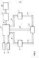
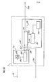
- Figure 2 shows a modified version of Figure 1 in which, rather than having a central controller, the audio and video test subsystems communicate with and are under the control of an isolated and independent interface subsystem and controller;
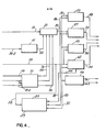
- Figure 3 is a more detailed block diagram of the audio/video quality monitoring system of Figure 1 showing the interrelationship between.the central controller and one of the plurality of interface subsystems and its associated audio and video test- subsystems;
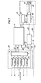
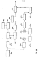
- Figure 4 is a block diagram showing a further breakdown of the audio test subsystem of Figure 3;
- Figure 5 illustrates a representation of a length of video tape showing the position of lead-in, lead-out program material, and track locations for audio and control and cue tracks;
- Figure 6 shows, in the upper half thereof, a spacial representation of the placement of audio test tones at the lead-in and lead-out portion of a video tape or video disc, and in the bottom half thereof, a pictorial representation of the signals in the corresponding blocks of the top-half of the figure;
- Figure 7 shows, in block diagram form, the audio test tone generator logic for creating the audio test tones for placement on lead-in and lead-out of the video tape or video disc;
- Figure 8 is a general block diagram illustration of the audio analysis logic portion of the audio test subsystem;
- Figure 9 illustrates a more detailed portion of the audio analysis logic, and in particular, the audio controller portion thereof;
- Figure 10 shows details of a portion of the audio analysis logic, and in particular, the audio and video selector, 6734 tone detector, and time code or frame number selector;
- Figure 11 shows the details of the multi-programmer portion of the audio analysis logic of Figure 8;
- Figure 12 is a timing chart showing the relationship between the signals operative for carrying out the audio analysis according to the logic diagram of Figure 8;
- Figure 13 illustrates, in block diagram form, the operative functional blocks of the video test subsystem;
- Figure 14 is a waveform showing the theoretical flattened portion of the waveform of the back porch of the horizontal blanking pulse immediately following the color burst signal;
- Figure 15 is a pictorial representation of the distribution of points on a video disc on which noise characteristics are measured;
- Figure 16 shows, in block diagram form, the circuitry useful in measuring the noise content on the back porch of the horizontal blanking pulse of Figure 14;
- Figure 17 is a general block diagram showing the video analysis logic associated with the video test subsystem;
- Figure 18 is a general block diagram of the audio/video data evaluation subsystem;
- Figure 19 is an overall procedural block diagram showing the manner in which tape evaluation is accomplished according to the present invention;
- Figure 20 is an overall procedural block diagram showing the manner in which the disc evaluation is accomplished according to the present invention;
- Figure 21 is an overall procedural block diagram showing the manner in which the throughput device evaluation is accomplished according to the present invention; and
- Figure 22 is an overall procedural block diagram showing the manner in which the digital signature evaluation is accomplished according to the present invention.
- Figure 1 shows a complete audio/video quality monitoring system utilizing a
central controller 1 and a plurality of terminals each comprising aninterface subsystem 3, an audio/video test subsystem 2, and the unit under test 4 connected to the audio/video test subsystem 2. The peripheral equipment associated with thecentral controller 1 comprises amemory unit 13, akeyboard 70, adata evaluation subsystem 19, and a data readout device ordevices 64. - While Figure 1 shows a single
central controller 1 withmultiple interface subsystems 3, an alternative to such a "centralized" system is the arrangement of Figure 2 in which eachinterface subsystem 3 is inclusive of its own, perhaps less sophisticated, controller, and has itsown memory unit 13,keyboard 70, anddata readout devices 64. Figure 2 further shows a slightly more detailed communication link between the various components of the interface, test, and evaluation subsystems. - Figure 3 shows a greatly expanded version of the arrangement shown in Figure 1 with
central controller 1 and its associated peripheral equipment connected with only asingle interface subsystem 3,audio test subsystem 5,video test subsystem 7, and unit under test 4. To this point, the unit under test 4 has been treated as strictly a player-type unit capable of reproducing audio and video signals from a prerecorded tape or disc. The phrase "unit under test", however, carries with it, for the purposes of this application, a more complex arrangement comprised of a tape recorder/player 11, adisc player 9, and an audio andvideo selector 53 as shown within the unit under test block 4 in Figure 3. The disc player is capable of outputting both video and audio signals to theselector 53 onlines player 11 outputs video online 149, and audio online 153. Later, it will be evident that theaudio lines - Operation control, i.e., stop, play, reverse, fast forward, rewind, etc., is effected by
operation control 117 ininterface substystem 3 viacable 133 shown in Figure 3 as a single line for simplifying the drawing. Operation control is also effective to select either audio channel, or both, and video from either thedisc player 9 or tape recorder/player 11. Audio and video are thus outputted onlines video selector 53. - Tape position is outputted on the data channel output line of the tape player-11, and audio test tones are applied to the tape by
tape recorder 11 as will be discussed in connection with more detailed figures later. - Having reference to Figures 3 and 4, the function of the audio test subsystem will now be described.
- Upon receiving a customers tape, a duplicate is made, and while the duplicate copy is properly termed a submaster, it is also referred to as a pre-mastering tape preparatory to producing a disc master. In any event, the first step in the process is to transfer the customer's program from the master tape to a submaster or pre-mastering tape. Simultaneously with the transferring of the video portion of the program to the pre-mastering tape, appropriate video test signals are inserted on
lines - In Figures 3 and 4, the data channel from the
tape player 11 is outputted online 34 and is sent totime code selector 51, a second input of which is a time code signal fromtime code register 116 as set up by thekeyboard 70 viacentral controller 1. The operator thus rewinds the tape onrecorder 11 to a position upstream of the start position for the test tones and sets the tape recorder into a recording mode through actuation ofoperation control 117 overline 133. When the time code ondata channel line 34 matches the time code fromregister 116, thetime code selector 51 sends an output compare signal to theaudio controller 21 which then initiates, overline 30,test tone generator 49 to apply test tones to bothchannels tape recorder 11. - In a similar manner, after the test tones have been applied to the lead-in portion of the tape, the operator performs a high speed tape wind to a point corresponding to the end of the active program and enters a second beginning point for the test tones to occur, during lead-out of the tape, beginning at least 150 frames after the program end. Under control of
central controller 1, when the operator permits the tape to resume normal speed prior to passing the end of active program area, a match is again detected bytime code selector 51 at at least 150 frames after the program end, the tape recorder is put into record mode, and thetest tone generator 49 is enabled byaudio controller 21 to deposit test tones onchannels tape recorder 11. - It is contemplated that the present invention can be utilized to insert audio test tones in between isolated program segments, as well as during lead-in and lead-out locations.
- In any event, the method of characterizing the information transfer characteristics of the recording medium basically involves recording, and simultaneously making a first measurement of, known values of one or more test signals on the recording medium, followed by playing back the recording medium and making a second measurement of the recorded test signal or signals. In the manner of establishing a "signature" as a representation of the signal transfer characteristics, and unlike prior art procedures involving merely checking properties of the medium (e.g., magnetic properties of a video tape), deviation levels from the first measurement results are set up as prescribed tolerance limits for the aforementioned second measurement, and the results of the first measurement are compared with the results of the second measurement to determine if the second measurement results are within the prescribed tolerance limits established from the first measurement results.
- When testing throughput devices (such as amplifiers, printed circuit boards, microelectronic chips, etc.), or in generally applying the present invention, analyzing the signal transferring characteristics of a signal processing unit can be accomplished by establishing an input signal of known content, measuring selected parameters of selected parts of such input signal, feeding that input signal to the signal processing unit, measuring the parameters of parts of the output signal from the signal processing unit corresponding to the similar selected parts of the input signal, and comparing the selected parameters of the input signal with the corresponding parameters of the output signal. Again, the tolerance limits for the measurement of parameters of the output signal are derived as deviation levels from the measurement of the corresponding parameters of the selected parts of the input signal.
- A method of analyzing the signal transfer characteristics of a signal processing unit will now be described in a slightly modified version than previously described, in that advantage is taken of an information storage device which can retain information gathered quickly from the unit under test and which can be accessed later for information analysis. In effect, the method involves establishing an input signal of known content, measuring selected parameters of selected parts of the input signal, storing the input measurement results to define a stored signature of the input signal comprising the selected parameters of selected parts of the input signal, feeding the input signal to the processing unit, measuring the parameters of parts of the output signal from the signal processing unit corresponding to selected parts of the input signal, and subsequently comparing the parameters of the output signal with the corresponding input signature parameters. When it is desirable to carry out the actual evaluation of the output signal measurements at a later time, the method of analyzing just described can be supplemented by a further step in the evaluation process. That is, before comparing the output signal measurement with the stored selected input signature parameters, the measurements of the output signal can also be stored to define a stored signature of the output signal comprising selected parameters of selected parts of the output signal, and the comparing step would then comprise comparing the stored output signal signature with the stored input signal signature. Reference is made to Figures 3 and 4 and the following discussion for an understanding of this aspect of the invention.
- A 6734 head tone is recorded and retrieved from only one channel (e.g.,
channel 2 of a two channel audio program). This head tone identifies the beginning of the audio test tone sequence, and the audio on line 58 (Figure 3) or line 58-2 (Figure 4) from the audio andvideo selector 53 is routed to the 6734tone detector 41. The output of 6734detector 41 is routed overline 82 to theaudio controller 21 which provides, under internal process control, all of the timing functions for the remainder of theaudio test subsystem 5. -
Audio controller 1 is enabled preparatory to the system recognizing the 6734 tone burst by the operator, throughkeyboard 70,central controller 1, andinterface subsystem 3 by the sending of a request to the audio subsystem to load its internal acquisition program and to activate the audio test subsystem. - At the time audio test signals were generated and applied to the tape, a SMPTE start code is entered by the tape operator to indicate the start of active program as expressed in hours and minutes. Similarly, a SMPTE end code as entered by the tape operator indicates the end of active program as expressed hours and minutes. Thus, upon command from the operator to perform tape or disc evaluation, the
central controller 1, viainterface subsystem 3, enables theaudio controller 21 in theaudio test subsystem 5 overline 18 with an "enable" signal. - The central controller then instructs the operator to rewind and start the tape or disc from the beginning. The central controller sends the SMPTE start code minus 25 seconds to the
interface subsystem 3 and loads it into time code registers 116. In the same manner as previously described with-depositing the test tone sequence to the pre-mastering tape,time code selector 51 alerts theaudio controller 21 overline 76 that lead-in of the tape or disc is being read. With theaudio controller 21 now enabled, detection of the 6734 tone burst initiates the action ofaudio controller 21 to perform its timing sequences for the various analyzing functions of the audio test subsystem overline 30. One of the output control signals overline 30 is a control and trigger signal routed to themultiprogrammer 23. Upon receipt of the control and trigger signal,multiprogrammer 23 digitizes the segmented audio test tones online 58, stores the digitized version of the test tones in memory, and under control of theaudio controller 21, converts a selected segment of the audio test tones to a continuous analog representation and sends such representation overline 46 toaudio signal analyzer 25 for general analysis, and toaudio spectrum analyzer 27 for spectrum analysis of the lead-in and lead-out test tones. Direct audio online 58 from the audio/video selector 53 is routed to an activeprogram spectrum analyzer 43 and a mono/non-mono signal check 62, the former performing spectrum analysis of selected portions of the active program material, and the latter making a determination as to whether or not the two audio signals on the two audio channels of the playback audio are substantially the same or different, thereby indicating that the audio portion of the program is either monophonic or non-monophonic. The term "stereo" is not used in describing the function of thesignal check block 62, since the invention is equally suited for analyzing audio signals on the two channels in the form of monophonic, stereophonic, or totally separate audio tracks. - The outputs of each of the signal analysis blocks of the audio test subsystem are routed to a
data evaluation subsystem 19 which, under instructions from the operator throughcentral controller 1 compares the audio analysis results with standards, i.e., performs a signature comparison, and outputs the results of the evaluation onto aprinter 15 orvisual display 17. - With specific reference to Figure 3, the video from audio and
video selector 53overline 118 is routed to thevideo test subsystem 7, the video signal being converted from analog to digital form by A/D converter 123, the digitized version being stored indigital memory 124 and selectively processed or analyzed invideo processor 125. The output ofvideo processor 125 is thus a video "signature" of the recovered video signal, is outputted overline 126 to thedata evaluation subsystem 19, and the thus obtained output "signature" is compared with a stored signature in thedata evaluation subsystem 19, the results of which is printed onprinter 15 and/or displayed atdisplay station 17. - Program start and end signals on
line 76 and evaluate start online 78 all from code orframe number selector 51 enableaudio controller 21 to initiate and periodically check active audio as a result of decoding frame time codes from the vertical interval of the video received from the audio/video selector 53 online 118. - For purposes of illustration and to insure consistency of terminology used in this specification with that normally used and accepted in the art, references made to Figure 5 which shows a schematic representation of a length of video tape containing a lead-in portion, a lead-out portion, and a program material portion sandwiched therebetween. Assuming tape motion is to the right in Figure 5, the beginning of the
tape 55 has a lead-inportion 57, atest tone zone 59 on the lead-in portion, and aguard portion 65 of lead-in, all followed by theprogram material portion 67. Thetest tone zone 59 on lead-in is comprised of two tracks of audio test tones,track 1 being represented by numeral 61 andtrack 2 bynumeral 63. - In symmetrical fashion, following the
program material portion 67, a lead-out guard portion 65 precedestest tone zone 59 comprised ofaudio track 1 shown at 61,audio track 2 shown at 63, and lead-outportions 57 extending to the end of the tape. - The dotted line at 66 represents a control track for use in synchronizing the tape drive of the tape recorder upon playback, among other things, and a
cue track 68 upon which can be recorded a variety of signals, including tim code frame numbers, editing data, additional audio, etc. - Referring to Figure 6, in order to have a known measurable set of standards up on which to qualify audio signals, a segmented signal train of appropriate test signals is recorded on both the lead-in and lead-out areas of the pre-mastering tape. In a preferred embodiment of the invention, audio test tones are recorded on both audio channels of the tape and occupy 12 vertical frame times in corresponding areas on both of the audio channels as represented by the vertical dotted lines in Figure 6. Preceding the 12 frames of test tones, on
channel 2 is the 6734 test tone location signal. , - The top half of Figure 6 schematically shows the two
audio channels - When the contents of the first segment of the audio test tone train is analyzed, phase amplitude, signal-to-noise, and harmonic distortion measurements are taken. Since the two channels contain, for the durations of
segments segments - During
segments 4 and 7, each channel contains a DC level, and thus noise level measurements are taken during these time slots. - A prescribed summation of 60HZ and 7KHZ tones is contained on
segments - Finally, segments 8-12 contain audio tones continuously sweeping through a wide range of frequencies, i.e., from 20HZ to 20KHZ, and the analysis of the recovered test tones in this area reflect the frequency response of the transfer characteristics.
- For the purposes of this invention, the contribution to the electronics involved in the recording/ playback process is considered negligible.
- Turning now to Figure 7, a schematic diagram is shown which produces the audio test tones. A test tone generator and
multiplexer 49 contains a plurality of function generators including a 6734generator 73, a1KNZ tone generator 75, a 60HZ tone generator 77, a7KHZ tone generator 79, asweep generator 81, and aDC source 83. - In the test tone recording process, upon command from the keyboard operator, an enabling signal over
line 18 is routed toaudio controller 21. The tape is rewound and put into play condition, whereupon the .SMPTE code derived by thecentral controller 1 is loaded into lead-inlocation register 87 and sent overline 86 tocomparator 91. As the tape progress in its play mode, aposition detector 85 reads the SMPTE time code off the datachannel tape recorder 11 and sends the detected position information overline 84 also tocomparator 91. After enabling of theaudio controller 21, thecontroller 21 interrogatescomparator 91 for detection of correspondence between the present position detected byposition detector 85 and the predetermined point at which lead-in test tone signals are to be applied, the latter location information taken from lead-inlocation register 87. When a'comparison is found, an output of thecomparator 91 overline 28 initiates the subsequent multiplexing action under control ofaudio controller 21. Basically,controller 21, overline 72, selectively and at a video vertical repetition rate enables one or two of the function generators feeding multiplexer 71. Multiplexer 71 then sums the outputs of the selected function generators, and outputs the desired combinations shown in Figure 6 overlines input channels tape recorder 11. - Simultaneously with detection of the compare signal on
line 28,audio controller 21 outputs a record enable signal online 80 totape recorder 11 in order to change the recorder from the play to the record mode so that the audio test tones will be deposited, in the fashion shown in Figure 6, on the separate audio channels. - Control of forward, reverse, play, and stop motions of the
tape recorder 11 are effectuated under control ofaudio controller 21 over the lines incable 133. Not shown in Figure 7 are communication links between thecentral controller 1,interface subsystem 3, and theaudio test subsystem 5 which communicate the operator's keyboard commands to the audio controller for effectuating the various motion functions of thetape recorder 11. These are typical control communication paths which can be inplemented in a variety of known ways. - A general block diagram of the audio analysis logic is shown in Figure 8. In the manner described in connection with Figure 3, both a
disc player 9 and a tape recorder/player 11 are shown connected to an audio selector 53 (the audio portion of audio and video selector 53) the two audio outputs ofdisc player 9 being carried byline 32, while the two channels out of thetape player 11 are carried byline 16.Channels audio selector 53 are carried on lines 58-1 (channel 1) and 58-2 (channel 2). It will be noted thatonly channel 2 audio is sent to the 6734detector 41, consistent with the waveforms shown in Figure 6. The audio on line 58-1 enters A/D converter 37, is digitized thereby and sent overline 36 to the digitizedtest tones memory 33 for storage. Under command of theaudio controller 21, a control and trigger signal online 30 is effective to cause recirculate control 99-1 to recirculate a selected test tone segment in the digitizedmemory 33 and output that selected tone segment in a continuous manner overline 38 to D/A converter 39. The continuous representation of the selected test tone is then routed overline 46 to theaudio signal analyzer 25 and lead-in/lead-out spectrum analyzer 27 as described briefly earlier. The outputs of the twoanalyzers lines audio analysis memory 47. Thememory unit 45 thereof has information written into it bymemory write gates 44 which receive outputs from multiplexer 42 in a timed manner under control ofaudio controller 21 overline 30. Thus, all inputs to the multiplexer 42 are sequentially acted upon to be stored inmemory unit 45 for later evaluation by the evaluation subsystem. - L The analysis of the appropriate locations during lead-in and lead-out for recovering audio test tones to be analyzed is controlled by outputting a signal on
line 28 fromcomparator 91 when the appropriate frame numbers during lead-in and lead-out have been detected. Whether the audio test subsystem is analyzing the tape or the disc, present position data is received overlines position detector 85. The present position is then routed overline 84 tocomparators Comparators audio controller 21 at coincidence thereof. In Figure 8, the twocomparators - That is,
comparator 95 makes a comparison of the time code contained in the video information of the active program material so as to identify program start, program end, and various points along the program material content at which active audio and/or video tests are to be carried out. On the other hand, since there is no video contained in the lead-in and lead-out portions of a tape or disc,comparator 91 must rely upon SMPTE time code detection from either the data channel out or audio out signals of the tape and disc player. - After lead-in analysis has been accomplished, the audio test subsystem proceeds to analyze active audio program material at predetermined time intervals during the active programming.,
Comparator 95 is thus provided with present position data from the vertical interval of the video signal, andlocation register 109, when matched with present position, outputs a program start signal to theaudio controller 21 to ready the audio controller for subsequent active program analysis control. At the first predetermined location in the active program wherein audio is to be analyzed, location register 111 will have a position location match with present position fromposition detector 85, andcomparator 95 will output an evaluate start signal overline 78 toaudio controller 21. Control then of two additional audio analysis functions of the audio test subsystem commences under control ofaudio controller 21 over the control line generally designated at 30 in Figure 8. - The audio from both channels of the playback device exiting
audio selector 53 enters active program twochannel spectrum analyzer 43.Analyzer 43 contains two analyzer arrays, one for each of the audio channels. Since the audio to be analyzed during active program material is continuous, it is not necessary to digitize and recirculate audio segments in themultiprogrammer 23 as was necessary with the short segment deration test tones of the lead-in and lead-out portions of the tape or disc. Accordingly, the audioentering spectrum analyzer 43 is selected audio direct from the playback devices. Botharrays spectrum analyzer 43 operate in identical fashion, i.e., a 45 second audio waveform from each audio channel is acquired and transformed into two frequency spectrum of 128 separate frequency points for each channel. Point spacing is in 200HZ increments, and each value analyzed at each point is expressed in decibels. The frequency spectrum for each sample represents a unique audio "print", and the 128 points for each channel have their values contained onlines memory unit 45. - Another part of the "signature", and therefore another input to multiplexer 42, is a signal on
line 454 indicating whether or not the audio portion of the program is monophonic or non-monophonic. The signal is developed in the mono/non-monosignal check block 62.Channel 1 andchannel 2 audio are received byblock 62 over lines 58-1 and 58-2, respectively, these two signals being compared with each other inamplitude comparator 105. Mono/non-mono testing is performed at intervals throughout the active programs areas of the tape or disc. Each test consists of 65,536 measurements, the measurements being spaced one millisecond apart. -
Block 62 illustrates a preferred embodiment of the mono/non-mono check in which the amplitudes of the two audio channels are continuously compared incomparator 105 with the difference between the two audio channels being outputed online 84. If the amplitudes are within 5% of each other,threshold detector 107 does not react to the signal online 84, there is no output online 86, and a 1KHZ clock 103 is applied overline 88 to the mono/non-mono counter 101. Without an input online 86, i.e. the amplitudes of the audio on both audio channels are within 5% of one another, counter 101 is incremented by 1 count. One millisecond later, as determined by the pulse recurrent rate of1KHZ clock 103, counter 101 is again incremented if the amplitudes are again within 5% of one another. This procedure continues in like manner until the measured amplitudes between the two audio channels are greater than 5% in difference, at whichtime threshold detector 107 outputs a step waveform online 86 to inhibit counter 101 from incrementing one count. As a result, after counter 101- permits 65,536 clock pulses to increment or not increment the counter, the accumulated count is sent overline 54 to multiplexer 42 and stored inmemory unit 45 bymemory write gate 44 to become a part of the "signature" for the unit tested. - Obviously, in the printout of the analysis performed by the audio test subsystem, the greater the number count on
line 54, i.e. the closer the accumulated count is to 65,536, the more definite it is that the two audio signals on the two audio channels are the same, i.e. the audio program is monophonic. - An alternate implementation of the mono/
non-mono check block 62 is represented by the dotted line 88' from1KHZ clock 103 toamplitude comparator 105. In this embodiment, the amplitude of the audio on the two channels 58-1 and 58-2 are not compared continuously, but rather are compared under the gating action of the 1KHZ clock, that is, a comparison is made every millisecond.Comparator 105 is then arranged such that, when the amplitudes of the signals of the two audio input lines 58-1 and 58-2 are within 5% of one another, an output pulse is routed tothreshold detector 107 alongline 84. The output ofthreshold detector 107 is then a step when the amplitudes on the two audio channels are within 5% of one another and DC when the amplitudes are greater than 5% of one another. Sincecomparator 105 is clocked at a 1KHZ rate, the maximum frequency step signal out ofthreshold detector 107 is also 1KHZ, and when a stereophonic or non-monophonic program is being and counter 101 is incremented fewer times. Again, assuming that amplitude comparisons are made incomparator 105 65,536 times, this embodiment of the mono/non-mono signal check merely counts the number of times that the amplitudes of the samples from the two audio channels are within a prescribed percentage tolerance of one another (5%) to provide information regarding whether or not the signals on the two channels are substantially similar in informational content. - Figure 9 is a more detailed diagram of the
audio controller 21, showing that is basically comprised of aprocessor 29 and read-only memory 31. Read-onlymemory 31 can take on any of various forms of memory such as tape cassette, hard wired or burned in micro chips, and the like. The purpose of the memory is to set up the control functions of the audio controller in a prescribed manner upon enablement by thecentral controller 1 and/or interface subsystem andline 18, the processor instructs the read-only memory 31 to prepare theprocessor 29 for outputting its control logic online 30, (representing a plurality of actual signal lines) depending upon subsequent signals received byprocessor 29. - In Figure 10, there is shown, in more detail than before, signal routing associated with the audio and
video selector 53 and time code orframe number selector 51. - The lead-in and lead-out identification signal, herein referred to as the 6734 tone or code signal, can, in a simplified system be comprised of a non-standard frequency such as 6734 HZ lasting the time of one picture frame preceding the sequence of test tones of the lead-in and lead-out portions of the tape or disc. However, a better identification signal is preferably a coded form for a sequence of numerical digits such as 6, 7, 3, and 4. The code is a self-clocking digital representation of the
number series 6734 which is chosen so as to remove from chance (for all practical purposes) the possibility that any other randomly recovered signal from tape or disc would falsely appear to be the identification signal. The coded digits are represented in binary by switching between two square wave source tones, a 1 KHZ tone and a 2.5 KHZ tone, according to 1 and 0 binary states, respectively. Upon detection by 6734detector 41, the transitions attributed to the 1 KHZ tone are interpreted as logital l's, while the transitions attributed to the 2.5 KHZ tone are interpreted as logical O's. Upon detection of a proper combination of l's and O's making up the binary representations of 6, 7, 3, and 4,detector 41 outputs a "match" signal to indicate that the series of lead-in and lead-out test signals follow. - Although the discussion so far has involved processing, analyzing, and evaluating audio program material,video signals are utilized in the audio test subsystem for the purpose of determining when active audio is to be analyzed, and such information is derived from the frame number codes in the vertical interval of the video signal. Accordingly, the video from disc player on
line 147 and the video from tape player online 149 are routed toselector 53, and _ depending upon which program is to be analyzed, disc or tape, an output video signal online 118 is rounted to framenumber selector 51. When the predetermined frame code from the interface subsystem on line 18-2 is compared with the video frame number code inselector 51, a "program start" signal is generated online 76 upon coincidence of the first frame of the active video program with the predetermined frame code number, and subsequently an "evaluate start" signal is generated online 78 upon coincidence of the predetermined points of analyzing the active audio portion of the program with predeatermined frame codes. Since audio analyzing is accomplished in a rather short period of time as compared with the length of most programs (e.g. 45 seconds for spectrum analysis and 65.5 seconds for mono/non-mono check), a number of predetermined frame codes on line 18-2 received byselector 51 will result in a plurality of spaced "evaluate start" signals online 78. - Details of the
multiprogrammer 23 is shown in Figure 11. The purpose of themultiprogrammer 23 is to receive audio in online 58 from the lead-in and lead-out portion of the program and to output a continuous version of the audio online 46. Additionally, multiprogrammer receives a control and trigger online 30 for synchronizing the inner workings of the multiprogrammer, and outputs a 1KHZ clock as the one millisecond timing signal for mono/non-mono signal check 62. - The segmented audio test signal train is received one
line 58 and converted to digital form by A/D converter 37. Upon sensing the 6734 tone indetector 41,audio controller 21 sends control and trigger signals alongline 30 to the program storage 35, A/D converter 37, andtimer pacer 103. - Control to program storage 35 merely resets the internal program of the multiprogrammer so as to acquire, recirculate, and output audio at the appropriate times. The trigger on
line 30 to pulser 97 andpacer 103 is generated upon detection of the 6734 start tone. Typically,pulser 97 outputs a 32KHZ square wave for activation of the A/D converter 37, whilepacer 103 outputs a 64KHZ square wave for digital-to-analog conversion timing in D/A converter 39. The 1KHZ clock output online 88a is the basic timing source for the mono/non-mono check block 62. In this connection, the1KHg clock circuit 103 in Figure 8 shades the closk for distribution within the mono/non-mono check bloe4 62 . - With the digitizing pulses configured as described above, A/
D converter 37 converts the real-time audio in online 58 and stores it inacquisition storage 33. It should be recalled that, subsequent to the 6734 start tone, twelve segments of audio test tones are received bymultiprogrammer 23, and at a 30 frame per second rate, all twleve frames will be written intoacquisition storage 33 in 0.4 seconds. - In order to analyze a continuous form of each segment of the audio test train in lead-in and lead-out, program storage 35, under control of
audio controller 21, retreives, in turn, each selected segment of the audio test tone train, recirculates it via - control of recirculate control 99 overline 80, and causes a continuous form of the particular selected segment to be outputted overline 38. D/A converter 39, timed bypacer 103, then outputs a continuous analog version of the selected audio test tone segment overline 46 for analyzing by thesignal analyzer 25 andspectrum analyzer 27 shown in Figures 4 and 8. - The functioning of the audio test subsystem has been described in terms of signal routing between circuit blocks of the foregoing figures. Figure 12 should serve to clarify the signal routing details and provide a timing analysis of the many signals described only verbally heretofore. The audio waveform of
channel 1 is shown schematically at 90 in Figure 12, while thechannel 2 waveform is shown at 92. The beginning of the tape or disc is to the left in Figure 12. Bothchannels - Since only lead-in and lead-out test tones are acquired from the recording medium of a rate too fast for analyzing, only these test signals need to be digitized, stored, and recalled for further analysis at a later time. Accordingly, digitized audio waveform 94 indicates that
multiprogrammer 23 is performing its digitizing under control ofaudio controller 21 only during lead-in and lead-out time. As explained earlier, analysis of the program material is accomplished in real-time and need no digitizing technique applied. - "Program start" waveform 96 occurs as a single pulse at the beginning of the program material. As explained earlier, this pulse is sent to the
audio controller 21 to clear and reset the internal audio processer preparatory to taking active audio samples for analysis. - On the other hand, "evaluate start" waveform 98, occurs periodically throughout the program material and is shown by way of example in Figure 12 as occurring four times. Since the longest active analyzing time is approximately 65.5 seconds, it is obvious that "evaluate start" pulses could occur at a corresponding or slightly lower rate.
- Figure 12 shows an "evaluate start" pulse at the beginning of program material, and as a result, the count from counter 101 (Figure 8) begins to be accumulated. Waveform 100a shows a plurality of counts occurring at a 1KHZ rate, and assuming that a theoretical monophonic signal has been recorded in both
audio channels -
Audio controller 21, overline 80, createswaveform 104 having "save accumulated count and clear counter"pulses 106 applied to mono/non-mono counter 101 so as to output the accumulated count overline 54 to be analyzed byaudio analysis memory 47, having reference again to Figure 8. - In a similiar manner,
audio controller 21 creates the approximate 45 second enablingpulse 110 ofwaveform 108 to activate thespectrum analyzer 43, and during the relaxation time after the 45second analysis pulse 110, apulse 114 shown onwaveform 112 is effective to causespectrum analyzer 43 to output the test results from the spectrum analyzer, such results being referred to "spectral print" to become a part of the signature after evaluation. - Shown in Figure 13 is the video test subsystem. The
video subsystem 7 comprises essentially two logical units, anacquisition unit 119 and aprocessing unit 125.Acquisition unit 119 has the capability to acquire a video signal in a controlled manner, convert it from analog signal to digital values in A/D converter 123 and store a digitized signal in acquisitiondigital memory 124 overline 130. Typically,digital memory 124 has 32K bytes of acquisition memory, and an analog-to- digital conversion results in an 8 bit byte. One of the 525 lines in a frame is represented by 910 conversions or bytes, converted in real-time, each Each picture horizontal line being 63.5 microseconds in duration. The video test signals are encoded during vertical intervals inlines processing unit 125, selected lines or portions of lines from a frame or from consecutive frames may be converted and stored until the 32K bytes of acquisition storage is filled. - Control of the
acquistion unit 119 and computation of the acquired data is performed by processingunit 125. Theprocessing unit 125 features amicroprocessor computer 120,processing storage 121, and a real-time clock 122. Having acquired and stored the selected video test signals, control ofprocessing unit 125 is effected by acontrol line 135 frominterface subsystem 3. In a manner of control analogous to that associated with the audio test subsystem discussed earlier,microprocessor computer 120 accesses overline 128 the digitized and stored video test signal fromdigital memory 124 overline 127. Time based from real-time clock 122 overline 129,computer 120 andprocessing storage 121 interplay to output overline 126 the analog equivalent of the video test signal or portion thereof being processed and route same to the data evaluation subsystem to become a part of the "signature" of the tape or disc being evaluated.lines field 1,line 20 and with appropriate measuring devices can provide some 15 measurements of different video parameters. - A combination VITS video test signal is located on each frame in
field 2,line 20 and provides some 11 measurable parameters. - Finally, a VIRS test signal is located in each . frame in both vertical fields on
line 19 to provide some 9 additional measurable parameters. Modern - video test equipment can be used to measure substantially all of the VITS and VIRS test signals. - An exception lines in the noise test which is generally carried out during vertical interval times of a broadcast program.
- A standard test procedure for evaluating noise levels is to measure the peak-to-peak amplitude of the noise deviation during the horizontal sync pulse which is theoretically to be at a DC level for approximately 4 microseconds. On a video disc, and especially on one which uses a constant angular velocity (CAV) format, if the noise test was taken only during vertical interval, only a small percentage of the disc's surface area would be contributory to the noise measurement. This is illustrated in Figure 15 which shows, schematically, the two vertical interval V-shaped
portions 207, and assuming the disc rotates.in a counterclockwise direction, the dottedline 208 represents the position at which noise tests would normally be taken, i.e., on a given horizontal sync tip- at a given line number of each vertical interval. Even if such a noise test were taken during each vertical interval between alternate fields, it can be appreciated by reference to Figure 15 that only a very slim localized area of the disc would be evaluated by the noise test. Accordingly, and consistent with one of the objects of the present" invention to perform evaluation tests on video discs, the noise test according to the present invention is taken on each horizontal blanking pulse of any desirable portion of video program. As shown in Figure 14, theback porch 201 of the horizontal blanking pulse following the color burst 180 has a theoretically flat shape during the time indicated byarrow 202. According to the present invention, a noise evaluation is made during the time indicated byarrow 202, and since this is accomplished on each horizontal blanking pulse, substantially the entire area of the disc can be tested for noise problems, and this is shown in Figure 15- wherein, rather than the radial line of evaluation shown at 208, noise figures are taken from the disc at each of the dash lines 209. Although only two rows ofdash lines 209 are shown represented in Figure 15, it can be appreciated that each of some 54,000 circles of dashedlines 209 would show on a full scale drawing, and therefore it can be appreciated that any blemishes on a disc outside the vertical interval will be taken into account in the noise measurement. This represents a substantial improvement in videodisc quality assurance as compared with the normal noise tests taken only on a singlehorizontal sync tip 200 as seen in Figure 14, and then only during vertical interval occurrences. - A block diagram of the circuitry used for effectuating the unique noise test according to the aforedescribed procedure is shown in Figure 16. Figure 16 should be analyzed with a view to Figure 13 wherein like numbers represent like functional blocks of the two diagrams. In the noise test arrangement of Figure 16 video in over
line 118 is'digitized in analog/digital converter 123 and advanced to a sample and holdcircuit 137. Sample and holdcircuit 137 makes eight samples of thewaveform portion 202, shown in Figure 14, and stores the results indigital memory 124. The processing of the noise test data is accomplished in separate fields of the video signal. It should also be noted that, since it is necessary for the sampling of thecircuit 137 to sample identical parts of adjacent horizontal blanking signals, only the horizontal blanking signals outside the vertical interval are noise tested. Accordingly, typically about 480 lines per frame are sampled for the noise test measurement. - The video of
field 1 is routed to mean detector 139-1 which calculates the mean value for the eight samples, and the variance detector 141-1 outputs the variance from the mean, such variance being forwarded to the averagingcircuit 152. In like manner, the sampled noise offield 2 is routed to mean detector 139-2, the variance from the mean thereof being detected by variance detector 141-2, and the results also sent to averagingcircuit 152. The average of the two noise figures are thus outputted online 126 as measurement data out, and such measurement data is sent to the data evaluation subsystem to be discussed later. - With reference to Figure 17, the video analysis logic is shown. Because the testing of different sources of video program material require different control of the sample points for making measurements, a
memory 138 is provided to contain a list of frames to be measured. Upon receiving an "enable" signal frominterface subsystem 3,controller 142 initiates forward, reverse, stop, and play functions of thedisc player 9 ortape player 11 to ultimately cause one of these devices to output its video information overlines video selector 53. In the meantime,controller 142 clears over line 161counter 140, and the first frame number to be measured is outputted frommemory 138 overline 169 tocomparator 136. When the video online 118 out ofvideo selector 53 is decoded as to frame number byframe decoder 134, a comparison incomparator 136 is made, and a "take measurement" signal online 157 is routed tocontroller 142.Controller 142 then initiates the testing of thevideo test subsystem 7 by outputting an "enable" signal online 175. Simultaneously,controller 142 enables memory writegates 144 so that the video test data online 126 out ofvideo test subsystem 7 can be stored overlines 167 intovideo analysis memory 146. The position inmemory 146 to which each test analysis signal is to be written is controlled byaddress bus 165 having coincidence with the frame number under test. - Upon conclusion of memory storage for one sampling of video test signal, the second in the list of frames to be measured is outputted from
memory 138 overline 169, and another comparison is made incomparator 136 with present frame number in order to again instructcontroller 142 to "take measurement" overline 157.Controller 142uninhibits memory gates 144 to again write the new test data analysis inmemory 146 at the address from counter 140 overaddress bus 165. Again,controller 142 increments over line 163counter 140 so that the next frame number to be measured is read out ofmemory 138. - This process continues until all of the test samples have been taken for analysis by
video test subsystem 7 and written intomemory 146. The output ofmemory 146, as discussed earlier, is routed overline 126 to the evaluation subsystem. - Figure 18 shows a block diagram of the audio/video data evaluation subsystem. As explained in connection with Figures 3, 4, 8, 13, and 16, all of the audio and video analysis data from either tape, disc, or throughput device, is sent to the data evaluation subsystem. Prior to processing in the
evaluation subsystem 19, the analytical processing by the electronics has been referred to supra as "analysis". In this specification, the term "evaluation" has the special meaning of processing the "analysis" information in such a manner so as to "evaluate" the unit under test, and in a specific practical application of the invention, such evaluation is tantamount to a pass or fail statement for the unit under test. - Although throughput devices have been described earlier as being evaluatable using the concepts of this invention, Figure 18 shows the typical evaluation of audio and video from a copy of a master program. A block numbered 211 represents the audio analysis data from the master source of program material, while
block 212 represents the analysis of corresponding data from the copy made from the master. Similarly, master video analysis is represented byblock 213, while corresponding video analysis of the copy is represented byblock 214. Anaudio comparator 215 compares the master and copy analysis data, and the differences are routed to aprinter 15 to enable visual and permanent storage of the list of differences. Similarly, video comparator 216 processes the differences in video analysis between master and copy and prints the results in the list of differences. As will be seen in subsequent figures, the audio andvideo comparators 215 and 216 do more than make mere line-for-line comparisons of the signals from master and copy, but rather involve the unique concept of comparing "signatures" as hereinbefore defined. - Figures 19-22 illustrate different "evaluation" schemes utilizing the concepts of the present invention. The first of these figures, Figure 19, "tape evaluation", shows that a
video tape 154 is prepared by recording onprogram tape recorder 145 the picture and/or sound from aprogram source 143. Generally, the picture and sound program source is that of a customer's master video tape or a motion picture film. In either case,tape 154 is prepared from the customer's tape or film program source for the purposes of usingtape 154 as a pre-mastering tape for eventual use in preparing the disc master. At the time the program is recorded ontape 154 byrecorder 155, appropriate video test signals fromtest signal generator 148 are recorded during the vertical interval portions of the program. In preparing thepre-mastering tape 154, sufficient time is left before the program material and after the program material on the tape so as to allow for insertion of the lead-in and lead-out audio test tones. Thus, at the time the program is recorded on thepre-mastering tape 154, or at a later time, as desired, audio test tones are recorded on tape recorder 150 (ortape recorder 145 if desired), and the resultingtape 154 now contains lead-in test tones, program material, and lead-out test tones. - A
player 156 outputs the audio and video signals to theirrespective analyzer 158, and the characteristics of the test parameters measured byanalyzer 158form parameter list 154 which can take the form of a visual display or hard copy readout. At this point, other than the application of audio test tones during lead-in and lead-out, "tape analyzing" has been accomplished, and the character of the tape is reflected in the analysis of the tested parameters listed inparameter list 164, and this type of analyzing is not uncommon in the tape manufacturing field. The present invention, however, goes beyond mere analysis of a signal source in that, from theparameter list 164, parameter deviation limits are set, either manually or under computer control bylimits setter 166. The range of parameter deviations permitted bylimits setter 166 can be established by applying a percentage figure to the measured parameter of theparameter list 164 and storing the deviation limits so derived in asignature store 168. Desirably, prior to the listing of the parameter analyzed inparameter list 164, a fixed standards table 162 is used as a common (e.g. NTSC, PAL, or SECAM) standard for comparing the output of theanalyzer 158 incomparator 160. For example, where the Federal Communications Commission, SMPTE, EIA, or other standards group has established precise parameter tolerance limitations on audio and video signals,comparator 160 ensures that the parameters listed inparameter list 164 are within such industry standards. On the other hand, limitssetter 166 is more in line with acceptable limits permitted by the particular process involved in a particular manufacturer's recording process. Thus, when a copy is made ofpre-mastering tape 154, corresponding signals from master and copy are analyzed inanalyzer 158 and evaluated inevaluator 171 by comparing the signature 4insignature store 168 with the output ofanalyzer 158. The quality of the copy is thus compared against essentially two standards, the industry accepted standards according to standards table 162, and an internal manufacturer's standards set bylimits setter 166. As a result, the signal evaluated byevaluator 171 is not merely weighted against fixed industry standards as has been done in the past, but is rather compared against a "signature" which is representative of the character of the recording process which should be repeatable within certain limitations. In this way, the degradation of the copying process can be evaluated against a more realistic reference, i.e., against a previously recorded signal using the same kind of tape, same recorder, and same signal source so that these latter items can be nullified as to their contributory effects. - As compared with analyzing processes which evaluate a recovered tape signal against fixed, often calculated, standards, evaluating a copy, or similar recorded program, against a "signature" permits the manufacturer to pinpoint smaller out-of-tolerance deviations and thus allow isolation of the problem areas of a process so that corrective action can be taken. Similarly, comparing against a "signature" characteristic can show the degrading effect of a process even when the signal retrieved from the second and subsequent recordings are within tolerances as compared to fixed standards. In other words, it is conceivable that for a particular recording process, the test results of analyzing a particular parameter is within extremely tight limits and of more optimum value than industry standards requires. As a result, the signature will reflect an unusually high standard for that particular parameter. This is a result of setting the limits on the basis of prior test results and not industry standards. Thus, 4As some part of the recording process degrades, for example, in the production of the tape itself,
evaluator 171 may fail a tested unit because the parameter of interest lies outside the limits set bylimits setter 166, even though analysis of that parameter shows that it is within acceptable industry standards according to standards table 162. Knowing the relationship between the manufacturing process for the tape and the particular parameter tested, immediate corrective action can be taken. Otherwise, such a defect, especially in combination with other defects, could render the product (tape in this example) unusable, and such knowledge would come to the attention of the manufacturer after the fact, i.e., after receiving many complaints by its customers. -
Evaluator 171 may be implemented in some form of sophisticated comparator in which each of a large number of parameter values fromanalyzer 158 is compared with a pair of numbers for each such value stored insignature store 168, the two values fromsignature store 168 being upper and lower limits within which the parameter being evaluated must fall. The evaluation output signal is then a printed table of data showing a list of parameters, the tolerances established bylimits setter 166, the value of each parameter being evaluated byevaluator 171, and out-of-tolerance limits information. A sample of a table so constructed is shown in Tables I, II, and III which are more closely associated with the "disc evaluation" shown in Figure 20. - Referring to Figure 20, the "disc evaluation" scheme is represented. Here, the same components are shown as were shown in Figure 19 with the addition of the
disc mastering recorder 173 and associated functional blocks. In this scheme,evaluator 171 evaluates the tape signature stored insignature store 168 relative to the corresponding disc signature stored insignature store 231. Whenpre-mastering tape 154 is played inplayer 156, assuming that a tape "signature" has been acquired as described in connection with Figure 19, the program material and test tones are transferred tovideo disc 177 by"disc mastering recorder 173. It is to be noted that both lead-in and lead-out signals are transferred to thevideo disc 177 along with program material in order that analysis of a disc can be performed using the same test signal sources as those associated with the pre-mastering tape.Blocks 217 through 223 represents the major process steps in the production of a video disc from exposure and development inblock 217 through applying adhesive and putting together the two disc halves to form a completed two-sided disc inblock 223. Adisc player 224 then plays the completed disc, and the results are analyzed inanalyzer 226 in a manner similar to that ofanalyzer 158. Again, it is preferable to compare the output ofanalyzer 226 with fixed standards from a standard's table 227 in acomparator 225. This kind of preliminary checking eliminates those discs which might contain defects causing the parameters tested to be very far out of acceptable industry standard limits. Additionally, and common to all evaluation schemes in Figures 19-22 performing this initial analysis against "world" standards is a check on the quality of a customer's original material, and this can be of great benefit when deviations from such "world" standards can be detected early, e.g., before disc mastering is initiated. - In any event, assuming the results of
analyzer 226 are tolerable against fixed industry standards, the analyzer results are sent to signature table 229 and stored insignature store 231. Recalling that the lead-in and lead-out test tones are accumulated in real time in less than one-half second and that certain audio and video tests are performed oil the active program material, under manual or computer control,evaluator 171 recalls the tape signature fromstore 168 and the disc signature fromstore 231 and compares parameter-for-parameter the two signatures. Again, a visual display or hard print readout is available to show how well the particular disc has performed against its pre-mastering counterpart (reference again Tables I, II and III). - The importance of measuring like parts of the copy and master has been mentioned previously, and the logic and wisdom of this is rather obvious. Accordingly, in addition to the "signature" containing parameter analysis results and tolerance range limits, it is essential that the "tape signature" comprise in its make-up the particular frame numbers at which video and audio active program analysis is to take place. In this manner, the "personality" of a "signature" is totally characterized with all of the information to make a signature comparison at any time and at any step in the process, in Figure 20, for example, the master disc has a photoresist layer at point A in the process, is exposed and developed at point B, metalized at point C, made into a stamper at point D to produce a one-sided (IX) plastic replica at point E, provided with a reflective coating at point F, and a protective coating at point G, and finally, combined with a second-half disc to form a completed disc (2X) at point H.
- It is important to note at this point that, as with any replicating process, some degradation of the program material through each step of the process can be expected at points A-H. Furthermore, the degradation to be expected between points A and B may be less than that expected between points B and C, etc. Accordingly, an application of the present invention concerns playing the disc from any point in the process and establishing a "signature" for each of the points A through H. The invention thus provides substantially "real-time" evaluation for correlation with "in process" activities to cause supervisorial personnel to shut down or modify equipment before any great loss of material and employee time. Additionally, out-of-tolerance parameter trends can be readily sensed, and the information gathered by comparing process signatures at each step in the process, so as to improve specific manufacturing processes or process steps due to the highly accurate and repetitive objective testing capabilities that "signature" testing provides. Such trend information can be used to foresee potential problems, even though on an absolute scale, the parameters tested are within acceptable limits. Finally, by varying the process parameters at each major step in the process, product improvement-can be enhanced by observing the "signature" comparisons when temperatures, pressures, process times, etc., are varied.
- Concerning "disc evaluation", in view of the fact that video disc players are of recent design, the present invention can be used in evaluating player consistency. For example, instead of changing discs in Figure 20, the same disc can be played back on a number of
disc players 224, and a "signature" of the players can be developed and compared with the "signature" established from a known good player. - The use of this invention with "throughput" devices, such as audio and video amplifiers and special effects devices, i.e., echo units, distribution amplifiers, limiters, and the like, has been mentioned earlier. Figure 21 shows such a scheme.
- Since the evaluation procedure requires preparing a "signature" of a throughout
reference unit 234, a separate path for a throughput undertest 235 is shown in Figure 21. The unit under test is shown to have itsown analyzer 226, signature table 229, andsignature store 231. Of course, in the interest of economy, a scheme similar to that of Figure 19 could also have been used, whereinanalyzer 158 could be time shared with the referencedunit 234 and unit undertest 235. In such a case,analyzer 226, signature table 229, andsignature store 231 would be unnecessary. - Likewise, in case of need, rather than taking the output of
analyzer 158 in Figure 19 directly toevaluator 171, a separate analyzer, signature table,


- Finally, Figure 22 illustrates the manner in which digital signature evaluation is accomplished. The same analogy follows in this figure insofar as forming a signature in
store 168. However, whether the signal to be evaluated is audio or video, a player, termed device undertest 238, outputs its signal to the A/V converter 237, and the digital form of the signal is stored indigital memory 233. If necessary, as was with the audio test tones during lead-in and lead-out, arecirculate control 240 feeds back the selected digital portion of the stored signal in a loop around fashion so as to output a continuous version of the stored signal to D/A converter 239. The analog version of the signal is then analyzed inanalyzer 226, a signature table is established, and the analyzing results are stored insignature store 231 for later evaluation incomparator 171. - Table I is a printout of the results of "signature" evaluation during lead-in of a video disc. The selected parameters analyzed for the disc example used are listed in the lefthand column, and the "signature" comparison is shown in the two groups of three columns each, one group for
audio channel 1 and another group foraudio channel 2. The center column for each channel lists the value of the disc analysis measurement for each parameter, while the two values on either side of the center column indicate the "signature" limits set bylimits setter 166 of Figure 20. - Table II shows similar evaluation comparison results for lead-out of the disc under test.
- In like manner, Table III shows the video evaluation test results. Here, an additional column of information is shown, that of the actual tape analysis measurements from which upper and lower limits for the "signature" comparison were generated in
limits setter block 166. - In this connection, the twelve segments of audio lead-in tones are retrieved at the rate of 30 segments per second (vertical frame rate), and instruments such as the Hewlett Packard 8903A Audio Analyzer are available which can measure a given parameter in typically 2.5 seconds or less. Since each segment of the lead-in test tones is used for more than one audio measurement, it is recirculated, as explained earlier, to produce a continuous version thereof for the length of time necessary to perform all audiq measurements by the analyzer before going on to retrieving and continuously looping the second test segment.
- Since a large number of measurements may be made at any one test frame, and since the available analyzer can perform its analysis in 2.5 seconds or less, the maximum length of time necessary for the analyzer to make say as many as 11 measurements in
test frame 1 is about 27.5 seconds. Accordingly, the recirculate control 99 shown in Figures 8 and 11 need only recirculate the tone segment for a maximum time of 27.5 seconds. Furthermore, and although the present invention is not limited to the specific tests listed above, to complete all 23 audio test measurements would require no more than 57.5 seconds. Conservatively then, the repetition rate at which the complete audio measurement cycle is repeated can conservatively be one cycle every minute. Then, since the longest active program test is the nono/non-mono check, and since this check can be completed each 65.5 seconds, it is clear that advantage can be taken of the AVQMS system to weed out defective discs in only a few minutes of recording/playing time. This concept can be carried out on video discs produced by the method illustrated in Figure 20 (as opposed to the direct read-after-write process) so as to be able to detect defective discs at any point along the process in only a few minutes. Of course, defects not contained close to the lead-in portion of the disc being evaluated will not show up instantaneously, but process defects which cause uniform parameter degradation throughout the video disc will be caught in the first couple of minutes of playing time. Furthermore, the speed at which information can be analyzed with the AVQMS eliminates much time taken in manually observing and/or manually taking measurements under prior techniques. Then again, all subjective evaluation of the disc is eliminated. - Only preferred embodiments of the invention have been described above. One skilled in the art, however, will recognize that where audio signal measurements were made in the manner of Figures 7-11, clearly video signal measurements,custom or standard, can be performed in a similar manner. Accordingly, the blocks labeled with "audio" designations merely need being renamed to illustrate the equivalent manner of multiplexing and subsequent analyzing of the lead-in and lead-out for video qualities (with appropriate changes of signal sources and timing figures, of course.)
- Similarly, the manner in which video parameter analysis and evaluation have been described herein could, with like analogy, apply to the analysis and evaluation of audio parameters.
Claims (4)
Priority Applications (1)
| Application Number | Priority Date | Filing Date | Title |
|---|---|---|---|
| AT83111951T ATE31991T1 (en) | 1982-01-12 | 1982-09-14 | METHOD AND DEVICE FOR DETERMINING THE CHARACTERISTICS OF A PRE-RECORDED TWO-CHANNEL AUDIO SIGNAL. |
Applications Claiming Priority (2)
| Application Number | Priority Date | Filing Date | Title |
|---|---|---|---|
| US339011 | 1982-01-12 | ||
| US06/339,011 US4746991A (en) | 1982-01-12 | 1982-01-12 | Recording characteristic evaluation of a recording medium with a time sequence of test signals |
Related Parent Applications (1)
| Application Number | Title | Priority Date | Filing Date |
|---|---|---|---|
| EP82108473.8 Division | 1982-09-14 |
Publications (2)
| Publication Number | Publication Date |
|---|---|
| EP0113425A1 true EP0113425A1 (en) | 1984-07-18 |
| EP0113425B1 EP0113425B1 (en) | 1988-01-13 |
Family
ID=23327082
Family Applications (9)
| Application Number | Title | Priority Date | Filing Date |
|---|---|---|---|
| EP83111951A Expired EP0113425B1 (en) | 1982-01-12 | 1982-09-14 | Method of and apparatus for establishing the characteristics of a prerecorded two-channel audio program |
| EP83111964A Expired EP0117910B1 (en) | 1982-01-12 | 1982-09-14 | Apparatus for signal evaluation by accumulation at one rate and releasing and testing at a slower rate |
| EP84112826A Ceased EP0152535A3 (en) | 1982-01-12 | 1982-09-14 | Method and apparatus for encoding an information storage medium with audio test signals |
| EP83111962A Expired EP0117908B1 (en) | 1982-01-12 | 1982-09-14 | Method of and apparatus for analyzing the signal transfer characteristics of a signal processing unit |
| EP82108473A Expired EP0083686B1 (en) | 1982-01-12 | 1982-09-14 | Audio/video quality monitoring system |
| EP83111963A Ceased EP0117909A1 (en) | 1982-01-12 | 1982-09-14 | Method of and apparatus for evaluating the audio characteristics under the control of a video picture frame number |
| EP83111960A Expired EP0116135B1 (en) | 1982-01-12 | 1982-09-14 | Method of evaluating and apparatus for analyzing recording characteristics of a recording medium with a prescribed analog electrical signal |
| EP88104680A Withdrawn EP0309639A3 (en) | 1982-01-12 | 1982-09-14 | A method of automatically evaluating the quality of an audio-video program recorded on a recording medium |
| EP83111961A Expired EP0113426B1 (en) | 1982-01-12 | 1982-09-14 | Method and apparatus for analyzing the information transfer characteristics of a recording medium |
Family Applications After (8)
| Application Number | Title | Priority Date | Filing Date |
|---|---|---|---|
| EP83111964A Expired EP0117910B1 (en) | 1982-01-12 | 1982-09-14 | Apparatus for signal evaluation by accumulation at one rate and releasing and testing at a slower rate |
| EP84112826A Ceased EP0152535A3 (en) | 1982-01-12 | 1982-09-14 | Method and apparatus for encoding an information storage medium with audio test signals |
| EP83111962A Expired EP0117908B1 (en) | 1982-01-12 | 1982-09-14 | Method of and apparatus for analyzing the signal transfer characteristics of a signal processing unit |
| EP82108473A Expired EP0083686B1 (en) | 1982-01-12 | 1982-09-14 | Audio/video quality monitoring system |
| EP83111963A Ceased EP0117909A1 (en) | 1982-01-12 | 1982-09-14 | Method of and apparatus for evaluating the audio characteristics under the control of a video picture frame number |
| EP83111960A Expired EP0116135B1 (en) | 1982-01-12 | 1982-09-14 | Method of evaluating and apparatus for analyzing recording characteristics of a recording medium with a prescribed analog electrical signal |
| EP88104680A Withdrawn EP0309639A3 (en) | 1982-01-12 | 1982-09-14 | A method of automatically evaluating the quality of an audio-video program recorded on a recording medium |
| EP83111961A Expired EP0113426B1 (en) | 1982-01-12 | 1982-09-14 | Method and apparatus for analyzing the information transfer characteristics of a recording medium |
Country Status (7)
| Country | Link |
|---|---|
| US (1) | US4746991A (en) |
| EP (9) | EP0113425B1 (en) |
| JP (2) | JPH0711548B2 (en) |
| KR (2) | KR880002665B1 (en) |
| AT (5) | ATE28958T1 (en) |
| DE (1) | DE3272153D1 (en) |
| HK (6) | HK16091A (en) |
Families Citing this family (40)
| Publication number | Priority date | Publication date | Assignee | Title |
|---|---|---|---|---|
| US4746991A (en) * | 1982-01-12 | 1988-05-24 | Discovision Associates | Recording characteristic evaluation of a recording medium with a time sequence of test signals |
| US4773094A (en) * | 1985-12-23 | 1988-09-20 | Dolby Ray Milton | Apparatus and method for calibrating recording and transmission systems |
| US5148291A (en) * | 1986-05-21 | 1992-09-15 | Canon Kabushiki Kaisha | Apparatus for displaying image signal drop-out |
| US4752825A (en) * | 1986-10-10 | 1988-06-21 | Grumman Aerospace Corporation | Video display simulator and analyzer |
| JPH0337801A (en) * | 1989-07-04 | 1991-02-19 | Jonan Denki Kogyosho:Kk | Inspecting device for recorded video tape |
| US6141300A (en) | 1989-06-20 | 2000-10-31 | Discovision Associates | Optical actuator including lens assembly with optical axis having symmetric suspensory forces acting thereon and optical disc system including same |
| US5265079A (en) | 1991-02-15 | 1993-11-23 | Applied Magnetics Corporation | Seek actuator for optical recording |
| US5121260A (en) * | 1989-06-22 | 1992-06-09 | Digital Equipment Corporation | Read channel optimization system |
| JPH03178057A (en) * | 1989-12-06 | 1991-08-02 | Sony Corp | Disk evaluating device |
| GB2239976B (en) * | 1989-12-20 | 1993-12-22 | Toshiba Emi Kk | Method of inspecting pancake tape |
| US5677899A (en) | 1991-02-15 | 1997-10-14 | Discovision Associates | Method for moving carriage assembly from initial position to target position relative to storage medium |
| US5808980A (en) * | 1991-02-15 | 1998-09-15 | Discovision Associates | Seek actuator for optical recording |
| US6069857A (en) | 1991-02-15 | 2000-05-30 | Discovision Associates | Optical disc system having improved circuitry for performing blank sector check on readable disc |
| US6236625B1 (en) | 1991-02-15 | 2001-05-22 | Discovision Associates | Optical disc system having current monitoring circuit with controller for laser driver and method for operating same |
| US5729511A (en) | 1991-02-15 | 1998-03-17 | Discovision Associates | Optical disc system having servo motor and servo error detection assembly operated relative to monitored quad sum signal |
| DE4124378A1 (en) * | 1991-07-23 | 1993-01-28 | Basf Magnetics Gmbh | METHOD FOR AUTOMATIC QUALITY MONITORING OF AUDIO VIDEO PROGRAMS, WHICH ARE RECORDED ON A RECORDING CARRIER |
| US5363250A (en) * | 1991-07-31 | 1994-11-08 | U.S. Philips Corporation | Prerecorded record carrier |
| JPH06131618A (en) * | 1991-12-27 | 1994-05-13 | Teac Corp | Method for recording and reproducing reference signal in magnetic tape |
| US5357520A (en) * | 1992-01-31 | 1994-10-18 | International Business Machines Corporation | Method and apparatus for precompensation value determination in a PRML data channel |
| GB9203911D0 (en) * | 1992-02-24 | 1992-04-08 | Emi Plc Thorn | Alignment corresponding segments of a digital signal and a digital reference signal |
| EP0564916B1 (en) * | 1992-04-10 | 2001-07-25 | Wea Manufacturing Inc. | Compact disc analyzer system |
| US5812506A (en) * | 1992-04-10 | 1998-09-22 | Wea Manufacturing, Inc. | System and methods for measuring and correcting for overshoot in a high frequency (HF) signal generated by a compact disc player during testing of a compact disc |
| US5450247A (en) * | 1992-11-06 | 1995-09-12 | Future Network, Inc. | Simultaneous contact duplication of a plurality of magnetic copy tapes from a single magnetic master tape |
| US5424881A (en) | 1993-02-01 | 1995-06-13 | Cirrus Logic, Inc. | Synchronous read channel |
| US5748578A (en) * | 1995-01-25 | 1998-05-05 | Discovision Associates | Colpitts type oscillator having reduced ringing and improved optical disc system utilizing same |
| US6091684A (en) * | 1995-01-25 | 2000-07-18 | Discovision Associates | Optical disc system and method for changing the rotational rate of an information storage medium |
| US5920539A (en) * | 1995-01-25 | 1999-07-06 | Discovision Associates | Apparatus and method for suppression of electromagnetic emissions having a groove on an external surface for passing an electrical conductor |
| US6434087B1 (en) | 1995-01-25 | 2002-08-13 | Discovision Associates | Optical disc system and method for controlling bias coil and light source to process information on a storage medium |
| US6269482B1 (en) * | 1997-07-14 | 2001-07-31 | Altinex, Inc. | Methods of testing electrical signals and compensating for degradation |
| US5927988A (en) * | 1997-12-17 | 1999-07-27 | Jenkins; William M. | Method and apparatus for training of sensory and perceptual systems in LLI subjects |
| US6157505A (en) * | 1998-06-19 | 2000-12-05 | The United States Of America As Represented By The Secretary Of The Navy | System and a method of operation thereof for analyzing the performance of a tape recorder |
| EP1245118A2 (en) * | 1999-12-03 | 2002-10-02 | MTI Film LLC | System and method for identifying inconsistencies in duplicate digital videos |
| GB2407910B (en) | 2003-11-05 | 2006-07-19 | Zoo Digital Group Plc | Automated testing of digital content |
| ITMI20040985A1 (en) * | 2004-05-17 | 2004-08-17 | Technicolor S P A | AUTOMATIC SOUND SYNCHRONIZATION DETECTION |
| EP1908211A2 (en) * | 2005-07-27 | 2008-04-09 | Doug Carson & Associates, Inc. | Verifying provenance data associated with digital content |
| JP2008016128A (en) * | 2006-07-06 | 2008-01-24 | Fujifilm Corp | Method and device for inspecting recording medium, and method and device for inspecting recording medium driving device |
| CN103747407B (en) * | 2013-12-27 | 2017-04-12 | 深圳英飞拓科技股份有限公司 | Audio module automatic test method based on FFT frequency sweep |
| CN106154096B (en) * | 2015-04-27 | 2019-12-10 | 中兴通讯股份有限公司 | audio connecting line detection method and device |
| CN105548865B (en) * | 2016-01-19 | 2018-07-06 | 歌尔股份有限公司 | A kind of camera module electrifying timing sequence testing device and test method |
| CN113096694B (en) * | 2019-12-23 | 2023-02-21 | 北京声智科技有限公司 | Electronic terminal and play quality detection method thereof |
Citations (4)
| Publication number | Priority date | Publication date | Assignee | Title |
|---|---|---|---|---|
| GB1198148A (en) * | 1966-09-30 | 1970-07-08 | Eastman Kodak Co | Control System for Re-Recording Apparatus |
| GB1408818A (en) * | 1973-06-25 | 1975-10-08 | Burroughs Corp | Magnetic recording verification |
| DE2650891A1 (en) * | 1976-11-06 | 1978-05-11 | Basf Ag | Sound recording quality control during playback from master tape - stores signal at certain tape part and same signal compared with it during subsequent playing |
| US4404603A (en) * | 1980-05-27 | 1983-09-13 | Warren Eugene D | Apparatus and method for inspecting magnetic tape recorded material for alterations |
Family Cites Families (24)
| Publication number | Priority date | Publication date | Assignee | Title |
|---|---|---|---|---|
| DE1084751B (en) * | 1959-07-02 | 1960-07-07 | Siemens Ag | Device to control magnetic image recording |
| US3225135A (en) * | 1960-06-25 | 1965-12-21 | Fuji Telecasting Co Ltd | Method and apparatus for monitoring a television tape recording operation |
| DE1159010B (en) * | 1962-12-04 | 1963-12-12 | Telefunken Patent | Monitoring and switching device for amplifier stages in television transmitters |
| US3551608A (en) * | 1967-04-07 | 1970-12-29 | Bell & Howell Co | Discrepancy indicator for record duplicating apparatus |
| US3576390A (en) * | 1968-05-29 | 1971-04-27 | Rca Corp | Apparatus for generating test signals useful in measuring television transmission performance without affecting receiver synchronization |
| US3517305A (en) * | 1968-10-22 | 1970-06-23 | Us Navy | Magnetic tape tester in which,after comparison with a standard,an erroneous signal is stored for later analysis |
| US3659044A (en) * | 1970-07-31 | 1972-04-25 | Rca Corp | Test system for electrical apparatus |
| DE2049259B1 (en) * | 1970-10-07 | 1972-03-23 | Fernseh Gmbh | System for the automatic testing of video studio equipment |
| US3879749A (en) * | 1973-08-20 | 1975-04-22 | Sencore Inc | TV test pattern and method of testing |
| US4003084A (en) * | 1973-11-28 | 1977-01-11 | Nasa | Method of and means for testing a tape record/playback system |
| US3932894A (en) * | 1974-03-14 | 1976-01-13 | International Business Machines Corporation | Magnetic record member for use with rotating head magnetic recording apparatus |
| US3938183A (en) * | 1974-10-03 | 1976-02-10 | The United States Of Amercia As Represented By The Secretary Of The Navy | Magnetic tape signature signal injection device |
| GB1532405A (en) * | 1974-11-01 | 1978-11-15 | Indep Broadcasting Authority | Television systems |
| DE2536585C3 (en) * | 1975-08-16 | 1981-04-02 | Philips Patentverwaltung Gmbh, 2000 Hamburg | Arrangement for statistical signal analysis |
| JPS5231777A (en) * | 1975-09-04 | 1977-03-10 | Matsushita Electric Ind Co Ltd | S/n ratio measuring apparatus |
| JPS5937784B2 (en) * | 1975-12-20 | 1984-09-12 | 日本ビクター株式会社 | Jikitape Karano Saisei Shingounoshingou Rebelno Heikinchi Hantei Hoshiki |
| JPS52123606A (en) * | 1976-04-09 | 1977-10-18 | Sony Corp | Recorder/reproducer |
| GB1604678A (en) * | 1978-05-30 | 1981-12-16 | Indep Broadcasting Authority | Television systems |
| DE2827422C3 (en) * | 1978-06-22 | 1985-01-31 | Wandel & Goltermann Gmbh & Co, 7412 Eningen | Method and circuit arrangement for measuring characteristic values of a quadrupole, in particular a data transmission link |
| JPS5575822A (en) * | 1978-12-05 | 1980-06-07 | Niigataken | Hydraulic bulging method for metallic container |
| US4408226A (en) * | 1980-01-11 | 1983-10-04 | Independent Broadcasting Authority | Test apparatus for monitoring digital transmissions |
| JPS5733409A (en) * | 1980-08-06 | 1982-02-23 | Sony Corp | Reproducer of coded signal |
| US4746991A (en) * | 1982-01-12 | 1988-05-24 | Discovision Associates | Recording characteristic evaluation of a recording medium with a time sequence of test signals |
| US4455634A (en) * | 1982-01-12 | 1984-06-19 | Discovision Associates | Audio/video quality monitoring system |
-
1982
- 1982-01-12 US US06/339,011 patent/US4746991A/en not_active Expired - Lifetime
- 1982-09-10 KR KR8204106A patent/KR880002665B1/en active
- 1982-09-14 AT AT83111962T patent/ATE28958T1/en not_active IP Right Cessation
- 1982-09-14 EP EP83111951A patent/EP0113425B1/en not_active Expired
- 1982-09-14 EP EP83111964A patent/EP0117910B1/en not_active Expired
- 1982-09-14 AT AT83111964T patent/ATE28713T1/en not_active IP Right Cessation
- 1982-09-14 EP EP84112826A patent/EP0152535A3/en not_active Ceased
- 1982-09-14 EP EP83111962A patent/EP0117908B1/en not_active Expired
- 1982-09-14 AT AT83111951T patent/ATE31991T1/en active
- 1982-09-14 EP EP82108473A patent/EP0083686B1/en not_active Expired
- 1982-09-14 EP EP83111963A patent/EP0117909A1/en not_active Ceased
- 1982-09-14 EP EP83111960A patent/EP0116135B1/en not_active Expired
- 1982-09-14 AT AT83111961T patent/ATE29638T1/en not_active IP Right Cessation
- 1982-09-14 DE DE8282108473T patent/DE3272153D1/en not_active Expired
- 1982-09-14 EP EP88104680A patent/EP0309639A3/en not_active Withdrawn
- 1982-09-14 EP EP83111961A patent/EP0113426B1/en not_active Expired
- 1982-09-14 AT AT83111960T patent/ATE37112T1/en not_active IP Right Cessation
- 1982-12-28 JP JP57227895A patent/JPH0711548B2/en not_active Expired - Lifetime
-
1988
- 1988-07-12 KR KR1019880008799A patent/KR880002667B1/en not_active IP Right Cessation
-
1991
- 1991-03-07 HK HK160/91A patent/HK16091A/en not_active IP Right Cessation
- 1991-03-07 HK HK154/91A patent/HK15491A/en not_active IP Right Cessation
- 1991-03-07 HK HK156/91A patent/HK15691A/en not_active IP Right Cessation
- 1991-03-21 HK HK208/91A patent/HK20891A/en not_active IP Right Cessation
- 1991-04-18 HK HK299/91A patent/HK29991A/en not_active IP Right Cessation
- 1991-04-18 HK HK300/91A patent/HK30091A/en not_active IP Right Cessation
-
1992
- 1992-12-14 JP JP4333067A patent/JP2839058B2/en not_active Expired - Lifetime
Patent Citations (4)
| Publication number | Priority date | Publication date | Assignee | Title |
|---|---|---|---|---|
| GB1198148A (en) * | 1966-09-30 | 1970-07-08 | Eastman Kodak Co | Control System for Re-Recording Apparatus |
| GB1408818A (en) * | 1973-06-25 | 1975-10-08 | Burroughs Corp | Magnetic recording verification |
| DE2650891A1 (en) * | 1976-11-06 | 1978-05-11 | Basf Ag | Sound recording quality control during playback from master tape - stores signal at certain tape part and same signal compared with it during subsequent playing |
| US4404603A (en) * | 1980-05-27 | 1983-09-13 | Warren Eugene D | Apparatus and method for inspecting magnetic tape recorded material for alterations |
Also Published As
Similar Documents
| Publication | Publication Date | Title |
|---|---|---|
| EP0117908B1 (en) | Method of and apparatus for analyzing the signal transfer characteristics of a signal processing unit | |
| US4455634A (en) | Audio/video quality monitoring system | |
| US4755884A (en) | Audio evaluation of information stored on a record medium under control of video picture frame number | |
| US5126990A (en) | Method of evaluating a storage medium by recirculating a test sample of a signal | |
| US4524444A (en) | Analyzing the signal transfer characteristics of a signal processing unit | |
| US4623837A (en) | Audio/video quality monitoring system | |
| US4682246A (en) | Characterizing the information transfer characteristics of a recording medium | |
| US4598324A (en) | Audio evaluation under control of video picture frame number | |
| US5001568A (en) | Signal evaluation by accumulation at one rate and releasing and testing at a slower rate | |
| US4764915A (en) | Method and apparatus for recording a multiplexed signal on a record medium | |
| US5256965A (en) | Quality inspecting method and apparatus for detecting defects in magnetic disks by dividing a plurality of concentric tracks into numbered sectors | |
| US4829249A (en) | Method of inspecting magnetic disks for surface defects | |
| EP0564916B1 (en) | Compact disc analyzer system | |
| KR880002653B1 (en) | Method and apparatus for analyzing the signal transfer characteristics of a signal processing | |
| KR880002666B1 (en) | Audio/video program | |
| KR880002651B1 (en) | Method and apparatus for analyzing the information transfer characteristics of a recording medium | |
| JPS62212546A (en) | Disk measuring apparatus | |
| SU1727172A1 (en) | Method of measurement of time distortions of video tape recorder | |
| EP0431859B1 (en) | Disc evaluating apparatus | |
| EP0014327A2 (en) | Electronic video tape evaluator | |
| JPH0720594Y2 (en) | Fluorescent magnetic particle flaw detector | |
| JPH02289915A (en) | Fm envelope waveform inspecting device for magnetic recording and reproducing device | |
| JPH08107571A (en) | Image inspection method | |
| JPH0371446A (en) | Disk evaluation device | |
| EP0110901A1 (en) | Data synchronization |
Legal Events
| Date | Code | Title | Description |
|---|---|---|---|
| PUAI | Public reference made under article 153(3) epc to a published international application that has entered the european phase |
Free format text: ORIGINAL CODE: 0009012 |
|
| 17P | Request for examination filed |
Effective date: 19831219 |
|
| AC | Divisional application: reference to earlier application |
Ref document number: 83686 Country of ref document: EP |
|
| AK | Designated contracting states |
Designated state(s): AT BE CH DE FR GB IT LI LU NL SE |
|
| 17Q | First examination report despatched |
Effective date: 19860313 |
|
| GRAA | (expected) grant |
Free format text: ORIGINAL CODE: 0009210 |
|
| AC | Divisional application: reference to earlier application |
Ref document number: 83686 Country of ref document: EP |
|
| AK | Designated contracting states |
Kind code of ref document: B1 Designated state(s): AT BE CH DE FR GB IT LI LU NL SE |
|
| REF | Corresponds to: |
Ref document number: 31991 Country of ref document: AT Date of ref document: 19880115 Kind code of ref document: T |
|
| REF | Corresponds to: |
Ref document number: 3277997 Country of ref document: DE Date of ref document: 19880218 |
|
| ET | Fr: translation filed | ||
| ITF | It: translation for a ep patent filed |
Owner name: SOCIETA' ITALIANA BREVETTI S.P.A. |
|
| PLBE | No opposition filed within time limit |
Free format text: ORIGINAL CODE: 0009261 |
|
| STAA | Information on the status of an ep patent application or granted ep patent |
Free format text: STATUS: NO OPPOSITION FILED WITHIN TIME LIMIT |
|
| 26N | No opposition filed | ||
| ITTA | It: last paid annual fee | ||
| EPTA | Lu: last paid annual fee | ||
| EAL | Se: european patent in force in sweden |
Ref document number: 83111951.6 |
|
| PGFP | Annual fee paid to national office [announced via postgrant information from national office to epo] |
Ref country code: FR Payment date: 20010817 Year of fee payment: 20 |
|
| PGFP | Annual fee paid to national office [announced via postgrant information from national office to epo] |
Ref country code: SE Payment date: 20010820 Year of fee payment: 20 Ref country code: DE Payment date: 20010820 Year of fee payment: 20 Ref country code: CH Payment date: 20010820 Year of fee payment: 20 |
|
| PGFP | Annual fee paid to national office [announced via postgrant information from national office to epo] |
Ref country code: NL Payment date: 20010821 Year of fee payment: 20 Ref country code: GB Payment date: 20010821 Year of fee payment: 20 Ref country code: AT Payment date: 20010821 Year of fee payment: 20 |
|
| PGFP | Annual fee paid to national office [announced via postgrant information from national office to epo] |
Ref country code: LU Payment date: 20010905 Year of fee payment: 20 |
|
| PGFP | Annual fee paid to national office [announced via postgrant information from national office to epo] |
Ref country code: BE Payment date: 20010914 Year of fee payment: 20 |
|
| REG | Reference to a national code |
Ref country code: GB Ref legal event code: IF02 |
|
| PG25 | Lapsed in a contracting state [announced via postgrant information from national office to epo] |
Ref country code: LI Free format text: LAPSE BECAUSE OF EXPIRATION OF PROTECTION Effective date: 20020913 Ref country code: GB Free format text: LAPSE BECAUSE OF EXPIRATION OF PROTECTION Effective date: 20020913 Ref country code: CH Free format text: LAPSE BECAUSE OF EXPIRATION OF PROTECTION Effective date: 20020913 |
|
| PG25 | Lapsed in a contracting state [announced via postgrant information from national office to epo] |
Ref country code: NL Free format text: LAPSE BECAUSE OF EXPIRATION OF PROTECTION Effective date: 20020914 Ref country code: LU Free format text: LAPSE BECAUSE OF EXPIRATION OF PROTECTION Effective date: 20020914 Ref country code: AT Free format text: LAPSE BECAUSE OF EXPIRATION OF PROTECTION Effective date: 20020914 |
|
| BE20 | Be: patent expired |
Owner name: *DISCOVISION ASSOCIATES Effective date: 20020914 |
|
| REG | Reference to a national code |
Ref country code: GB Ref legal event code: PE20 Effective date: 20020913 |
|
| REG | Reference to a national code |
Ref country code: CH Ref legal event code: PL |
|
| EUG | Se: european patent has lapsed |
Ref document number: 83111951.6 |
|
| NLV7 | Nl: ceased due to reaching the maximum lifetime of a patent |
Effective date: 20020914 |