EP0114505A1 - Apparatus and method for robot calibration - Google Patents
Apparatus and method for robot calibration Download PDFInfo
- Publication number
- EP0114505A1 EP0114505A1 EP83307827A EP83307827A EP0114505A1 EP 0114505 A1 EP0114505 A1 EP 0114505A1 EP 83307827 A EP83307827 A EP 83307827A EP 83307827 A EP83307827 A EP 83307827A EP 0114505 A1 EP0114505 A1 EP 0114505A1
- Authority
- EP
- European Patent Office
- Prior art keywords
- arm
- operative end
- target
- camera
- work station
- Prior art date
- Legal status (The legal status is an assumption and is not a legal conclusion. Google has not performed a legal analysis and makes no representation as to the accuracy of the status listed.)
- Granted
Links
Images
Classifications
-
- B—PERFORMING OPERATIONS; TRANSPORTING
- B23—MACHINE TOOLS; METAL-WORKING NOT OTHERWISE PROVIDED FOR
- B23P—METAL-WORKING NOT OTHERWISE PROVIDED FOR; COMBINED OPERATIONS; UNIVERSAL MACHINE TOOLS
- B23P19/00—Machines for simply fitting together or separating metal parts or objects, or metal and non-metal parts, whether or not involving some deformation; Tools or devices therefor so far as not provided for in other classes
- B23P19/10—Aligning parts to be fitted together
-
- A—HUMAN NECESSITIES
- A01—AGRICULTURE; FORESTRY; ANIMAL HUSBANDRY; HUNTING; TRAPPING; FISHING
- A01B—SOIL WORKING IN AGRICULTURE OR FORESTRY; PARTS, DETAILS, OR ACCESSORIES OF AGRICULTURAL MACHINES OR IMPLEMENTS, IN GENERAL
- A01B69/00—Steering of agricultural machines or implements; Guiding agricultural machines or implements on a desired track
- A01B69/007—Steering or guiding of agricultural vehicles, e.g. steering of the tractor to keep the plough in the furrow
- A01B69/008—Steering or guiding of agricultural vehicles, e.g. steering of the tractor to keep the plough in the furrow automatic
-
- B—PERFORMING OPERATIONS; TRANSPORTING
- B25—HAND TOOLS; PORTABLE POWER-DRIVEN TOOLS; MANIPULATORS
- B25J—MANIPULATORS; CHAMBERS PROVIDED WITH MANIPULATION DEVICES
- B25J19/00—Accessories fitted to manipulators, e.g. for monitoring, for viewing; Safety devices combined with or specially adapted for use in connection with manipulators
- B25J19/02—Sensing devices
- B25J19/021—Optical sensing devices
- B25J19/023—Optical sensing devices including video camera means
-
- B—PERFORMING OPERATIONS; TRANSPORTING
- B25—HAND TOOLS; PORTABLE POWER-DRIVEN TOOLS; MANIPULATORS
- B25J—MANIPULATORS; CHAMBERS PROVIDED WITH MANIPULATION DEVICES
- B25J9/00—Programme-controlled manipulators
- B25J9/16—Programme controls
- B25J9/1679—Programme controls characterised by the tasks executed
- B25J9/1692—Calibration of manipulator
-
- G—PHYSICS
- G05—CONTROLLING; REGULATING
- G05B—CONTROL OR REGULATING SYSTEMS IN GENERAL; FUNCTIONAL ELEMENTS OF SUCH SYSTEMS; MONITORING OR TESTING ARRANGEMENTS FOR SUCH SYSTEMS OR ELEMENTS
- G05B2219/00—Program-control systems
- G05B2219/30—Nc systems
- G05B2219/39—Robotics, robotics to robotics hand
- G05B2219/39057—Hand eye calibration, eye, camera on hand, end effector
Definitions
- This invention relates to robotics, and in particular it relates to a method and apparatus for calibrating a robot.
- the very essence of a robotic apparatus is that its movements are accurately predetermined so as to accurately carry out an intended operation such as handling or working on an object, the latter including, for example, welding or inspecting an object.
- Systems for guiding the robots through the course of their intended movements, to further enhance the accuracy of such movements have therefore been proposed.
- this is achieved in accordance with the present invention by calibrating the robot's position as it approaches the work station, utilizing sensing means independent from the robot's own system for predetermining and guiding the robot's movements, and'then sensing any deviation between a calibration signal and a reference signal. This deviation is then used to re-set the robot's basic computer guidance system. As a result thereof, as the robot's operative end approaches the work station, any error signals in its basic computerized program are re-set so that the robot's arm with its operating end are essentially given a fresh start from the location at which the calibration occurred, which will be in close proximity to the object, thereby in effect cancelling out any errors which preceded the point of calibration.
- Apparatus in accordance with the invention and having an arm with an operative end for automatically handling or working on an object at a work station is thus characterised by a computerized guidance means for controlling movements of the arm and operative end for carrying out an intended handling or working on the object, a calibration means for checking and if necessary re-setting the guidance means, the calibration means comprising means for sensing the position of the arm and operative end independently of the guidance means, as the arm and operative end approach the work station, for generating a calibration signal, and means for comparing the calibration signal against a reference signal and noting any deviation therebetween and for re-setting the computerized guidance means in response to the deviation.
- the calibration means comprises at least one target mounted on the arm and operative end, and including at least one camera mounted at a location independent of the arm and operative end appropriate for viewing the target as the arm and operative end approach the work station.
- one or more cameras are located on the robot's arm while the target or targets are located at fixed locations in the vicinity of the work station such as on the floor, on a pillar, on the fixed part of a conveyor, or the like.
- the cameras can be mounted at a remote location and in communication with sensing points on the robot's arm through fiber optics.
- the targets can be mounted on the robot's arm and the cameras located at fixed positions on the floor, pillars, or the like in the vicinity of the work station.
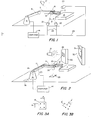
- Figure 1 illustrates a first preferred embodiment of the invention wherein a robotic apparatus 10 fixed to the floor includes an arm 11, in this case a multi- joint arm having an operative end 12. While this operative end can take any form for the purpose of handling or working on an object, including a camera which inspects an object, in the illustrated example there is shown an end effector 12.
- the work station 13, shown schematically in Figure 1, represents the area at which the operative end 12 would perform its function on the object.
- this system includes one or more targets mounted on the robot arm 11, as illustrated at 15 and 16, and one or more cameras, as illustrated at 20, 21 and 22, each of which cameras are fixed relative to the surrounding environment, as illustrated by the floor level, independently of the robot arm 11.
- the cameras communicate through lines 23 with the computer 14.
- a camera unit for example, camera 21 which may be fixed with respect to the floor and in fact buried in the floor of the plant at a location which is presighted with respect to the robot's own coordinate axis.
- camera 21 does not have to be presighted but it can be assured that the camera is returned to a certain initial condition point or in any event, its position relative to the robot can be determined.
- the target 15 has four dots. Three dots are the minimum for checking the position of the robot arm 11 up to six axes of coordinate data including X, Y, Z, roll, pitch and yaw.
- the fourth dot in the pattern provides a check and hence a more accurate calibration.
- the computer 14 dictated that the arm 11 should be in a certain predetermined position. Camera 21 will either confirm this position or note a deviation therein. If a deviation is noted, camera 21 will convey this information back to the computer 14 through lines 23, whereupon the computer 14 will make the corrections in the robot's memory for that position. Since the calibrating system is performing its function in a very limited area, i.e. only in the area close to the work station as the operative end 12 approaches same, it is only correcting the robot position over a very small range. This enables the system to have a high resolution, typically 0.02mm.
- a two camera solution may be desirable.
- a second camera 22 would be provided, which camera also views the target 15, this camera being spaced from the target 15 by an acute included angle 0 .
- the second camera can be located at position 20 which is 90° and in this case the camera would view a duplicate target 16.
- the targets may take many different forms such as white dots on a black background, illuminated points of diode lasers or light emitting diodes, fiber ends illuminated from a remote light source, etc.
- the camera units are typically solid state photo detector arrays of the type having a large number of separate photo detectors, and having an intrinsic digital measuring capability. Such units may have at least ten but preferably over a hundred separate photo detectors.
- a flashed (strobe)target illumination light 17 or flashed target points may be used. This provides the advantage of reading the dots and making the correction while the robot is in motion, i.e.”on-the-fly". If such a flashed light source is utilized, then a position sensing analogue photo detector such as a UDT SC-10 can be used. However, this is drift prone and therefore not necessarily suited to the most accurate mensuration. For calibration over larger zones of the work area, it may be necessary to mechanically sweep the field of view.
- Figure 2 illustrates a calibration system according to the present invention in which the basic features thereof have been reversed, i.e. in this case, the robot arm carries the cameras while the dotted targets are fixed with respect to the work station,i.e. on the floor, on pillars or the like, independently of the robot arm 11.
- Figure 2 illustrates a pair of cameras 25 and 26 mounted on the robot arm 11 and targets 28 and 29 fixed to the floor and to a pillar 30, respectively.
- a larger target 31 is mounted on a more distant pillar 32.
- Adding the cameras to the robot arm has the disadvantage of adding additional weight thereto.
- these cameras are relatively light.
- the camera can be located at a remote position, as illustrated diagrammitically at 35, and connected to viewing points at the end of the robot arm 11 through fiber optics 36.
- the robot arm 11 with the cameras thereon moves toward the work station 13 and as it approaches the work station the targets 28 or 29 come within view of the cameras 26 and 25, respectively.
- four dot matrix targets are desirable, although the system is operable for correcting in all six directions utilizing a minimum of three dots.
- the targets since the targets are not carried by the robot arm, the targets may be larger. Consequently, the accuracy of the solution may be considerably higher than in the case of a single closely spaced target. This is particularly true in range and angle dimensions.
- a target may be located directly behind a work object being conveyed such that when the work is transferred out, the target remains and is viewed by a camera, thus indicating removal of the object.
- many more target views can easily be utilized.
- the robot can be calibrated and hence corrected from a variety of angles by simply looking at the same target plate with different cameras or different points in time. This can give improved resolution as encoder errors are statistically averaged and the average of multiple transform equations are used. Since targets are cheap, one or more target plates can be used very easily.
- more than one camera can be used on the robot. Two are illustrated in this embodiment. Given the fiber optic system for remotely locating the camera, each camera can view different directions simultaneously.
- a strobe target illumination light 17 may be used for making readings on-the-fly. This can be important for maximum cycle rate since the robot need not stop.
- the flash source "freezes" the target image on the photodetector (for example, the matrix array) which then is read out subsequently. To accomplish this on the present matrix arrays, it may be necessary to provide a dump pulse to clear the array moments before the flash.
- the trigger to flash generally would come from the robot axis controller which would convey a signal indicating that the robot is at the calibration position.
- flash sources also provides good background light level discrimination. Where laser or light emitting diode sources are used, further discrimination results by using wave length band pass filters in front of the detector.
- targets may also be located on pallets, on automation equipment or on the objects themselves to provide a very local calibration to the robot axes.
- Figure 3 illustrates a practical example of the present invention using a typical four dot matrix target to correct in all six directions, X, Y, Z, ⁇ , 0 ⁇ , ⁇ .
- Figure 3A illustrates the correct reference position of the matrix, i.e. the view of the matrix if the robot arm 11 were perfectly positioned as the target came into the view of the camera.
- Figure 3B illustrates the matrix as actually viewed by the camera.
- the target image, as viewed on the computer screen is off center and tilted such that the distances a' and b' are less than the reference distances a and b. This indicates a tilt and also a Z axis range lengthening.
- These variables can be solved independently given equations such as are known in the photogrammetric art and referred to in the above noted Pinkney et al U.S. patent no. 4,219,847.
- the calibration system does not have to be permanently attached to the robot but can be brought up to it at any time, assuming that some reliable procedure exists for accurately positioning the calibration system for each subsequent application.
- periodic calibration of may robots in a plant can be done with a single calibration system.
Abstract
Description
- This invention relates to robotics, and in particular it relates to a method and apparatus for calibrating a robot.
- The very essence of a robotic apparatus is that its movements are accurately predetermined so as to accurately carry out an intended operation such as handling or working on an object, the latter including, for example, welding or inspecting an object. Systems for guiding the robots through the course of their intended movements, to further enhance the accuracy of such movements have therefore been proposed.
- However, no matter how perfect the original predetermined movements or no matter how accurate the guidance systems for enhancing the robot's movements, the nature of the environment in which the robots are utilised, including environmental conditions exterior to the robot make it virtually impossible to assure perfect positional accuracy at all times.
- For example, many robots, particularly multi- joint articulated robots, are generally not capable of maintaining their positional actions over a long period of time. Furthermore, when approaching a given desired position from different paths, they often provide different results, even when functioning as a result of the same computer input commands. This can be extremely difficult in a fully flexible automatic factory situation where different path commands may have to be generated by the computer and the robot is expected to follow them under all conditions. Apparatus quite suitable for the purpose of enhancing the accuracy of the predetermined robot movements is shown in U.S. patent no: 4,219,847.
- Hence, notwithstanding the improved means discussed above and known heretofore for enhancing guiding of the robot arm, there still exists a need to correct inaccuracies in the robot's position which cannot be corrected using known predetermined and improved guidance means and the primary object of the invention is to satisfy this need.
- In principle this is achieved in accordance with the present invention by calibrating the robot's position as it approaches the work station, utilizing sensing means independent from the robot's own system for predetermining and guiding the robot's movements, and'then sensing any deviation between a calibration signal and a reference signal. This deviation is then used to re-set the robot's basic computer guidance system. As a result thereof, as the robot's operative end approaches the work station, any error signals in its basic computerized program are re-set so that the robot's arm with its operating end are essentially given a fresh start from the location at which the calibration occurred, which will be in close proximity to the object, thereby in effect cancelling out any errors which preceded the point of calibration.
- Apparatus in accordance with the invention and having an arm with an operative end for automatically handling or working on an object at a work station is thus characterised by a computerized guidance means for controlling movements of the arm and operative end for carrying out an intended handling or working on the object, a calibration means for checking and if necessary re-setting the guidance means, the calibration means comprising means for sensing the position of the arm and operative end independently of the guidance means, as the arm and operative end approach the work station, for generating a calibration signal, and means for comparing the calibration signal against a reference signal and noting any deviation therebetween and for re-setting the computerized guidance means in response to the deviation.
- In a preferred arrangement, the calibration means comprises at least one target mounted on the arm and operative end, and including at least one camera mounted at a location independent of the arm and operative end appropriate for viewing the target as the arm and operative end approach the work station. In one arrangement, one or more cameras are located on the robot's arm while the target or targets are located at fixed locations in the vicinity of the work station such as on the floor, on a pillar, on the fixed part of a conveyor, or the like. In lieu of being mounted on the robot's arm, the cameras can be mounted at a remote location and in communication with sensing points on the robot's arm through fiber optics.
- In another arrangement, the targets can be mounted on the robot's arm and the cameras located at fixed positions on the floor, pillars, or the like in the vicinity of the work station.
- Examples in accordance with the present invention will now be described in more detail, with reference to the accompanying drawings, in which:-
- Figure 1 is a perspective, schematic view of a robot and its work station, utilizing the features of the present invention;
- Figure 2 is a schematic, perspective view similar to Figure 1 but showing a modification thereof; and
- Figures 3A and 3B are diagrammatic views of the target, illustrating the operation of the invention.
- There follows a detailed description of the preferred-embodiments of the invention, to be read together with the accompanying drawings, wherein like elements are represented by like numerals throughout the several views.
- Figure 1 illustrates a first preferred embodiment of the invention wherein a
robotic apparatus 10 fixed to the floor includes an arm 11, in this case a multi- joint arm having anoperative end 12. While this operative end can take any form for the purpose of handling or working on an object, including a camera which inspects an object, in the illustrated example there is shown anend effector 12. Thework station 13, shown schematically in Figure 1, represents the area at which theoperative end 12 would perform its function on the object. - In a known manner, the movements of the computer for purposes of carrying out the intended operation are controlled by
computer 14. However, since it is impossible to guarantee positional accuracy of theoperative end 12 under all conditions, there is provided in accordance with the present invention a system for checking and calibrating the position of the robot as it approaches thework station 13. In this embodiment this system includes one or more targets mounted on the robot arm 11, as illustrated at 15 and 16, and one or more cameras, as illustrated at 20, 21 and 22, each of which cameras are fixed relative to the surrounding environment, as illustrated by the floor level, independently of the robot arm 11. The cameras communicate throughlines 23 with thecomputer 14. - In the embodiment of Figure 1, as the robot's
operative end 12 approaches thework station 13, it passes itstarget 15 over a camera unit, for example,camera 21 which may be fixed with respect to the floor and in fact buried in the floor of the plant at a location which is presighted with respect to the robot's own coordinate axis. Alternatively, if repeatability is the only factor in question,camera 21 does not have to be presighted but it can be assured that the camera is returned to a certain initial condition point or in any event, its position relative to the robot can be determined. - As illustrated, the
target 15 has four dots. Three dots are the minimum for checking the position of the robot arm 11 up to six axes of coordinate data including X, Y, Z, roll, pitch and yaw. The fourth dot in the pattern provides a check and hence a more accurate calibration. Hence, as thetarget 15 approached the view ofcamera 21 thecomputer 14 dictated that the arm 11 should be in a certain predetermined position.Camera 21 will either confirm this position or note a deviation therein. If a deviation is noted,camera 21 will convey this information back to thecomputer 14 throughlines 23, whereupon thecomputer 14 will make the corrections in the robot's memory for that position. Since the calibrating system is performing its function in a very limited area, i.e. only in the area close to the work station as theoperative end 12 approaches same, it is only correcting the robot position over a very small range. This enables the system to have a high resolution, typically 0.02mm. - For further resolution, especially in other axes, a two camera solution may be desirable. In this case, a
second camera 22 would be provided, which camera also views thetarget 15, this camera being spaced from thetarget 15 by an acute included angle 0 . In the alternative, the second camera can be located atposition 20 which is 90° and in this case the camera would view aduplicate target 16. There may be provided a cube at the end of the robot arm having a plurality of these targets fixed thereon and of course geometrically fixed in reference with respect to each other. The targets may take many different forms such as white dots on a black background, illuminated points of diode lasers or light emitting diodes, fiber ends illuminated from a remote light source, etc. The camera units are typically solid state photo detector arrays of the type having a large number of separate photo detectors, and having an intrinsic digital measuring capability. Such units may have at least ten but preferably over a hundred separate photo detectors. - A flashed (strobe)
target illumination light 17 or flashed target points (diode lasers or light emitting diodes) may be used. This provides the advantage of reading the dots and making the correction while the robot is in motion, i.e."on-the-fly". If such a flashed light source is utilized, then a position sensing analogue photo detector such as a UDT SC-10 can be used. However, this is drift prone and therefore not necessarily suited to the most accurate mensuration. For calibration over larger zones of the work area, it may be necessary to mechanically sweep the field of view. - Figure 2 illustrates a calibration system according to the present invention in which the basic features thereof have been reversed, i.e. in this case, the robot arm carries the cameras while the dotted targets are fixed with respect to the work station,i.e. on the floor, on pillars or the like, independently of the robot arm 11. Figure 2 illustrates a pair of
cameras 25 and 26 mounted on the robot arm 11 and targets 28 and 29 fixed to the floor and to apillar 30, respectively. Alarger target 31 is mounted on a moredistant pillar 32. - Adding the cameras to the robot arm has the disadvantage of adding additional weight thereto. However, these cameras are relatively light. Moreover, as an improvement thereof, the camera can be located at a remote position, as illustrated diagrammitically at 35, and connected to viewing points at the end of the robot arm 11 through fiber optics 36.
- As illustrated in Figure 2, the robot arm 11 with the cameras thereon moves toward the
work station 13 and as it approaches the work station thetargets cameras 26 and 25, respectively. As in Figure 1, four dot matrix targets are desirable, although the system is operable for correcting in all six directions utilizing a minimum of three dots. In the embodiment of Figure 2, since the targets are not carried by the robot arm, the targets may be larger. Consequently, the accuracy of the solution may be considerably higher than in the case of a single closely spaced target. This is particularly true in range and angle dimensions. - In this embodiment with the targets fixed at selected locations in the vicinity of the work station, additional targets may be provided at especially advantageous points. For example, a target may be located directly behind a work object being conveyed such that when the work is transferred out, the target remains and is viewed by a camera, thus indicating removal of the object. Also, in the embodiment of Figure 2, many more target views can easily be utilized. Hence, the robot can be calibrated and hence corrected from a variety of angles by simply looking at the same target plate with different cameras or different points in time. This can give improved resolution as encoder errors are statistically averaged and the average of multiple transform equations are used. Since targets are cheap, one or more target plates can be used very easily. In addition, more than one camera can be used on the robot. Two are illustrated in this embodiment. Given the fiber optic system for remotely locating the camera, each camera can view different directions simultaneously.
- Also, in Figure 2, a strobe
target illumination light 17 may be used for making readings on-the-fly. This can be important for maximum cycle rate since the robot need not stop. The flash source "freezes" the target image on the photodetector (for example, the matrix array) which then is read out subsequently. To accomplish this on the present matrix arrays, it may be necessary to provide a dump pulse to clear the array moments before the flash. - In this case the trigger to flash generally would come from the robot axis controller which would convey a signal indicating that the robot is at the calibration position. Use of flash sources also provides good background light level discrimination. Where laser or light emitting diode sources are used, further discrimination results by using wave length band pass filters in front of the detector.
- It will be noted that the targets may also be located on pallets, on automation equipment or on the objects themselves to provide a very local calibration to the robot axes.
- Figure 3 illustrates a practical example of the present invention using a typical four dot matrix target to correct in all six directions, X, Y, Z, θ, 0̸, γ. Figure 3A illustrates the correct reference position of the matrix, i.e. the view of the matrix if the robot arm 11 were perfectly positioned as the target came into the view of the camera. However, Figure 3B illustrates the matrix as actually viewed by the camera. The target image, as viewed on the computer screen is off center and tilted such that the distances a' and b' are less than the reference distances a and b. This indicates a tilt and also a Z axis range lengthening. These variables can be solved independently given equations such as are known in the photogrammetric art and referred to in the above noted Pinkney et al U.S. patent no. 4,219,847.
- In addition, the dots in Figure 3B illustrate that the target is off center in both axes. All of the correction data is then fed into the
computer 14 to re-set the memory which controls the computers movements, whereupon the servos operating the robot arm 11 are actually moved to reposition the robot so that its target appears as in Figure 3A. This new position of the correct reading is then locked into the memory and becomes a new reference point from which the robot goes forward. - It is noted that the calibration system does not have to be permanently attached to the robot but can be brought up to it at any time, assuming that some reliable procedure exists for accurately positioning the calibration system for each subsequent application. Thus, once the system has been operated, periodic calibration of may robots in a plant can be done with a single calibration system.
Claims (13)
Applications Claiming Priority (2)
| Application Number | Priority Date | Filing Date | Title |
|---|---|---|---|
| US45391082A | 1982-12-28 | 1982-12-28 | |
| US453910 | 1982-12-28 |
Publications (2)
| Publication Number | Publication Date |
|---|---|
| EP0114505A1 true EP0114505A1 (en) | 1984-08-01 |
| EP0114505B1 EP0114505B1 (en) | 1987-05-13 |
Family
ID=23802543
Family Applications (1)
| Application Number | Title | Priority Date | Filing Date |
|---|---|---|---|
| EP19830307827 Expired EP0114505B1 (en) | 1982-12-28 | 1983-12-21 | Apparatus and method for robot calibration |
Country Status (2)
| Country | Link |
|---|---|
| EP (1) | EP0114505B1 (en) |
| DE (1) | DE3371487D1 (en) |
Cited By (111)
| Publication number | Priority date | Publication date | Assignee | Title |
|---|---|---|---|---|
| EP0149806A2 (en) * | 1984-01-18 | 1985-07-31 | International Business Machines Corporation | Robotic apparatus with improved positioning accuracy |
| FR2576005A1 (en) * | 1985-01-15 | 1986-07-18 | Realisa Indles Et | Automatic method and device for depalletising |
| EP0221643A3 (en) * | 1985-08-30 | 1988-10-12 | Texas Instruments Incorporated | Vision navigation system for free-roaming mobile robots |
| EP0330382A2 (en) * | 1988-02-23 | 1989-08-30 | The University Of British Columbia | Manipulator arm position sensing |
| EP0355050A2 (en) * | 1988-08-15 | 1990-02-21 | Kulicke And Soffa Industries Inc. | X-Y table error mapping apparatus and method |
| EP0456103A2 (en) * | 1990-05-11 | 1991-11-13 | International Business Machines Corporation | Image-directed robotic system for precise surgery |
| WO1991019240A1 (en) * | 1990-05-30 | 1991-12-12 | Fanuc Ltd | Calibration system of visual sensor |
| EP0528054A1 (en) * | 1991-03-07 | 1993-02-24 | Fanuc Ltd. | Detected position correcting method |
| US5219264A (en) * | 1986-09-19 | 1993-06-15 | Texas Instruments Incorporated | Mobile robot on-board vision system |
| EP0549805A1 (en) * | 1991-07-04 | 1993-07-07 | Fanuc Ltd. | Automatic calibration method |
| EP0560331A1 (en) * | 1992-03-11 | 1993-09-15 | Bodenseewerk Gerätetechnik GmbH | Positioning device for a part of the body for therapeutic treatment |
| FR2702856A1 (en) * | 1993-03-19 | 1994-09-23 | Deutsche Aerospace | Image-assisted position tracking method and device for carrying out said method. |
| WO1994029774A1 (en) * | 1993-06-11 | 1994-12-22 | Bertin & Cie | Method and device for spatial calibration of a mobile object such as a sensor or a tool carried by a robot |
| WO1995025475A1 (en) * | 1994-03-24 | 1995-09-28 | Elekta Instrument Ab | Device for detecting position of surgical instruments |
| US5602967A (en) * | 1981-05-11 | 1997-02-11 | Sensor Adaptive Machines, Inc. | Vision target based assembly |
| US5608847A (en) * | 1981-05-11 | 1997-03-04 | Sensor Adaptive Machines, Inc. | Vision target based assembly |
| DE19637822C1 (en) * | 1996-09-17 | 1998-03-26 | Deutsch Zentr Luft & Raumfahrt | Micromechanical tool |
| US6163946A (en) * | 1981-05-11 | 2000-12-26 | Great Lakes Intellectual Property | Vision target based assembly |
| US6167607B1 (en) | 1981-05-11 | 2001-01-02 | Great Lakes Intellectual Property | Vision target based assembly |
| WO2001000371A1 (en) * | 1999-06-26 | 2001-01-04 | Bae Systems Plc | Method and apparatus for calibrating visual guided robot |
| EP1152212A2 (en) * | 2000-03-29 | 2001-11-07 | VA TECH Transport- und Montagesysteme GmbH & Co | Device and procedure to calibrate the actuating arm of a robot |
| DE10237724A1 (en) * | 2002-08-17 | 2004-03-11 | Bayerische Motoren Werke Ag | Device for precision mounting tool relative to workpiece has several cameras in workpiece area and markers on tool and an evaluator unit to determine position of tool |
| WO2005108020A1 (en) * | 2004-05-04 | 2005-11-17 | Kuka Roboter Gmbh | Robot-controlled optical measurement array, and method and auxiliary mechanism for calibrating said measurement array |
| US7336814B2 (en) | 2004-07-14 | 2008-02-26 | Braintech Canada, Inc. | Method and apparatus for machine-vision |
| JP2010520075A (en) * | 2007-03-05 | 2010-06-10 | アブソルート ロボティクス リミテッド | Locating |
| US7957583B2 (en) | 2007-08-02 | 2011-06-07 | Roboticvisiontech Llc | System and method of three-dimensional pose estimation |
| US7967868B2 (en) | 2007-04-17 | 2011-06-28 | Biomet Manufacturing Corp. | Patient-modified implant and associated method |
| US8070752B2 (en) | 2006-02-27 | 2011-12-06 | Biomet Manufacturing Corp. | Patient specific alignment guide and inter-operative adjustment |
| US8095237B2 (en) | 2002-01-31 | 2012-01-10 | Roboticvisiontech Llc | Method and apparatus for single image 3D vision guided robotics |
| US8092465B2 (en) | 2006-06-09 | 2012-01-10 | Biomet Manufacturing Corp. | Patient specific knee alignment guide and associated method |
| US8133234B2 (en) | 2006-02-27 | 2012-03-13 | Biomet Manufacturing Corp. | Patient specific acetabular guide and method |
| US8170641B2 (en) | 2009-02-20 | 2012-05-01 | Biomet Manufacturing Corp. | Method of imaging an extremity of a patient |
| US8241293B2 (en) | 2006-02-27 | 2012-08-14 | Biomet Manufacturing Corp. | Patient specific high tibia osteotomy |
| US8265949B2 (en) | 2007-09-27 | 2012-09-11 | Depuy Products, Inc. | Customized patient surgical plan |
| US8282646B2 (en) | 2006-02-27 | 2012-10-09 | Biomet Manufacturing Corp. | Patient specific knee alignment guide and associated method |
| US8298237B2 (en) | 2006-06-09 | 2012-10-30 | Biomet Manufacturing Corp. | Patient-specific alignment guide for multiple incisions |
| US8343159B2 (en) | 2007-09-30 | 2013-01-01 | Depuy Products, Inc. | Orthopaedic bone saw and method of use thereof |
| US8357111B2 (en) | 2007-09-30 | 2013-01-22 | Depuy Products, Inc. | Method and system for designing patient-specific orthopaedic surgical instruments |
| US8377066B2 (en) | 2006-02-27 | 2013-02-19 | Biomet Manufacturing Corp. | Patient-specific elbow guides and associated methods |
| US8407067B2 (en) | 2007-04-17 | 2013-03-26 | Biomet Manufacturing Corp. | Method and apparatus for manufacturing an implant |
| US8437535B2 (en) | 2006-09-19 | 2013-05-07 | Roboticvisiontech Llc | System and method of determining object pose |
| US8473305B2 (en) | 2007-04-17 | 2013-06-25 | Biomet Manufacturing Corp. | Method and apparatus for manufacturing an implant |
| US8532807B2 (en) | 2011-06-06 | 2013-09-10 | Biomet Manufacturing, Llc | Pre-operative planning and manufacturing method for orthopedic procedure |
| US8535387B2 (en) | 2006-02-27 | 2013-09-17 | Biomet Manufacturing, Llc | Patient-specific tools and implants |
| US8559699B2 (en) | 2008-10-10 | 2013-10-15 | Roboticvisiontech Llc | Methods and apparatus to facilitate operations in image based systems |
| US8568487B2 (en) | 2006-02-27 | 2013-10-29 | Biomet Manufacturing, Llc | Patient-specific hip joint devices |
| US8591516B2 (en) | 2006-02-27 | 2013-11-26 | Biomet Manufacturing, Llc | Patient-specific orthopedic instruments |
| US8597365B2 (en) | 2011-08-04 | 2013-12-03 | Biomet Manufacturing, Llc | Patient-specific pelvic implants for acetabular reconstruction |
| US8603180B2 (en) | 2006-02-27 | 2013-12-10 | Biomet Manufacturing, Llc | Patient-specific acetabular alignment guides |
| US8608749B2 (en) | 2006-02-27 | 2013-12-17 | Biomet Manufacturing, Llc | Patient-specific acetabular guides and associated instruments |
| US8608748B2 (en) | 2006-02-27 | 2013-12-17 | Biomet Manufacturing, Llc | Patient specific guides |
| US8632547B2 (en) | 2010-02-26 | 2014-01-21 | Biomet Sports Medicine, Llc | Patient-specific osteotomy devices and methods |
| US8668700B2 (en) | 2011-04-29 | 2014-03-11 | Biomet Manufacturing, Llc | Patient-specific convertible guides |
| US8715289B2 (en) | 2011-04-15 | 2014-05-06 | Biomet Manufacturing, Llc | Patient-specific numerically controlled instrument |
| US8764760B2 (en) | 2011-07-01 | 2014-07-01 | Biomet Manufacturing, Llc | Patient-specific bone-cutting guidance instruments and methods |
| US8858561B2 (en) | 2006-06-09 | 2014-10-14 | Blomet Manufacturing, LLC | Patient-specific alignment guide |
| US8864769B2 (en) | 2006-02-27 | 2014-10-21 | Biomet Manufacturing, Llc | Alignment guides with patient-specific anchoring elements |
| US8956364B2 (en) | 2011-04-29 | 2015-02-17 | Biomet Manufacturing, Llc | Patient-specific partial knee guides and other instruments |
| US9060788B2 (en) | 2012-12-11 | 2015-06-23 | Biomet Manufacturing, Llc | Patient-specific acetabular guide for anterior approach |
| US9066734B2 (en) | 2011-08-31 | 2015-06-30 | Biomet Manufacturing, Llc | Patient-specific sacroiliac guides and associated methods |
| US9066727B2 (en) | 2010-03-04 | 2015-06-30 | Materialise Nv | Patient-specific computed tomography guides |
| US9084618B2 (en) | 2011-06-13 | 2015-07-21 | Biomet Manufacturing, Llc | Drill guides for confirming alignment of patient-specific alignment guides |
| US9113971B2 (en) | 2006-02-27 | 2015-08-25 | Biomet Manufacturing, Llc | Femoral acetabular impingement guide |
| US9125690B2 (en) | 2006-05-11 | 2015-09-08 | Brainlab Ag | Medical position determination using redundant position detection means and priority weighting for the position detection means |
| US9173661B2 (en) | 2006-02-27 | 2015-11-03 | Biomet Manufacturing, Llc | Patient specific alignment guide with cutting surface and laser indicator |
| US9204977B2 (en) | 2012-12-11 | 2015-12-08 | Biomet Manufacturing, Llc | Patient-specific acetabular guide for anterior approach |
| US9237950B2 (en) | 2012-02-02 | 2016-01-19 | Biomet Manufacturing, Llc | Implant with patient-specific porous structure |
| US9241745B2 (en) | 2011-03-07 | 2016-01-26 | Biomet Manufacturing, Llc | Patient-specific femoral version guide |
| US9271744B2 (en) | 2010-09-29 | 2016-03-01 | Biomet Manufacturing, Llc | Patient-specific guide for partial acetabular socket replacement |
| US9289253B2 (en) | 2006-02-27 | 2016-03-22 | Biomet Manufacturing, Llc | Patient-specific shoulder guide |
| US9295497B2 (en) | 2011-08-31 | 2016-03-29 | Biomet Manufacturing, Llc | Patient-specific sacroiliac and pedicle guides |
| US9301812B2 (en) | 2011-10-27 | 2016-04-05 | Biomet Manufacturing, Llc | Methods for patient-specific shoulder arthroplasty |
| CN105538341A (en) * | 2016-01-12 | 2016-05-04 | 昆明理工大学 | Robot calibration system and method based on incomplete end coordinate information |
| US9339278B2 (en) | 2006-02-27 | 2016-05-17 | Biomet Manufacturing, Llc | Patient-specific acetabular guides and associated instruments |
| US9345548B2 (en) | 2006-02-27 | 2016-05-24 | Biomet Manufacturing, Llc | Patient-specific pre-operative planning |
| US9351743B2 (en) | 2011-10-27 | 2016-05-31 | Biomet Manufacturing, Llc | Patient-specific glenoid guides |
| US9386993B2 (en) | 2011-09-29 | 2016-07-12 | Biomet Manufacturing, Llc | Patient-specific femoroacetabular impingement instruments and methods |
| US9393028B2 (en) | 2009-08-13 | 2016-07-19 | Biomet Manufacturing, Llc | Device for the resection of bones, method for producing such a device, endoprosthesis suited for this purpose and method for producing such an endoprosthesis |
| US9408616B2 (en) | 2014-05-12 | 2016-08-09 | Biomet Manufacturing, Llc | Humeral cut guide |
| US9451973B2 (en) | 2011-10-27 | 2016-09-27 | Biomet Manufacturing, Llc | Patient specific glenoid guide |
| US9498233B2 (en) | 2013-03-13 | 2016-11-22 | Biomet Manufacturing, Llc. | Universal acetabular guide and associated hardware |
| US9517145B2 (en) | 2013-03-15 | 2016-12-13 | Biomet Manufacturing, Llc | Guide alignment system and method |
| US9554910B2 (en) | 2011-10-27 | 2017-01-31 | Biomet Manufacturing, Llc | Patient-specific glenoid guide and implants |
| US9561040B2 (en) | 2014-06-03 | 2017-02-07 | Biomet Manufacturing, Llc | Patient-specific glenoid depth control |
| US9579107B2 (en) | 2013-03-12 | 2017-02-28 | Biomet Manufacturing, Llc | Multi-point fit for patient specific guide |
| CN106625774A (en) * | 2016-12-27 | 2017-05-10 | 中国科学院长春光学精密机械与物理研究所 | Space mechanical arm geometric parameter calibration method |
| US9675400B2 (en) | 2011-04-19 | 2017-06-13 | Biomet Manufacturing, Llc | Patient-specific fracture fixation instrumentation and method |
| US9795399B2 (en) | 2006-06-09 | 2017-10-24 | Biomet Manufacturing, Llc | Patient-specific knee alignment guide and associated method |
| US9820868B2 (en) | 2015-03-30 | 2017-11-21 | Biomet Manufacturing, Llc | Method and apparatus for a pin apparatus |
| US9826981B2 (en) | 2013-03-13 | 2017-11-28 | Biomet Manufacturing, Llc | Tangential fit of patient-specific guides |
| US9826994B2 (en) | 2014-09-29 | 2017-11-28 | Biomet Manufacturing, Llc | Adjustable glenoid pin insertion guide |
| US9833245B2 (en) | 2014-09-29 | 2017-12-05 | Biomet Sports Medicine, Llc | Tibial tubercule osteotomy |
| US9839438B2 (en) | 2013-03-11 | 2017-12-12 | Biomet Manufacturing, Llc | Patient-specific glenoid guide with a reusable guide holder |
| US9839436B2 (en) | 2014-06-03 | 2017-12-12 | Biomet Manufacturing, Llc | Patient-specific glenoid depth control |
| US9907659B2 (en) | 2007-04-17 | 2018-03-06 | Biomet Manufacturing, Llc | Method and apparatus for manufacturing an implant |
| US9918740B2 (en) | 2006-02-27 | 2018-03-20 | Biomet Manufacturing, Llc | Backup surgical instrument system and method |
| US9968376B2 (en) | 2010-11-29 | 2018-05-15 | Biomet Manufacturing, Llc | Patient-specific orthopedic instruments |
| CN108705518A (en) * | 2018-06-20 | 2018-10-26 | 珠海格力智能装备有限公司 | The processing method of industrial robot, apparatus and system |
| US10226262B2 (en) | 2015-06-25 | 2019-03-12 | Biomet Manufacturing, Llc | Patient-specific humeral guide designs |
| US10278711B2 (en) | 2006-02-27 | 2019-05-07 | Biomet Manufacturing, Llc | Patient-specific femoral guide |
| US10282488B2 (en) | 2014-04-25 | 2019-05-07 | Biomet Manufacturing, Llc | HTO guide with optional guided ACL/PCL tunnels |
| GB2574064A (en) * | 2018-05-25 | 2019-11-27 | Imetrum Ltd | Motion encoder |
| US10492798B2 (en) | 2011-07-01 | 2019-12-03 | Biomet Manufacturing, Llc | Backup kit for a patient-specific arthroplasty kit assembly |
| US10568647B2 (en) | 2015-06-25 | 2020-02-25 | Biomet Manufacturing, Llc | Patient-specific humeral guide designs |
| US10603179B2 (en) | 2006-02-27 | 2020-03-31 | Biomet Manufacturing, Llc | Patient-specific augments |
| US10722310B2 (en) | 2017-03-13 | 2020-07-28 | Zimmer Biomet CMF and Thoracic, LLC | Virtual surgery planning system and method |
| US10926414B2 (en) | 2017-09-29 | 2021-02-23 | Industrial Technology Research Institute | System and method for calibrating tool center point of robot |
| US11051829B2 (en) | 2018-06-26 | 2021-07-06 | DePuy Synthes Products, Inc. | Customized patient-specific orthopaedic surgical instrument |
| US11179165B2 (en) | 2013-10-21 | 2021-11-23 | Biomet Manufacturing, Llc | Ligament guide registration |
| US11419618B2 (en) | 2011-10-27 | 2022-08-23 | Biomet Manufacturing, Llc | Patient-specific glenoid guides |
| EP4335599A1 (en) * | 2022-09-12 | 2024-03-13 | fruitcore robotics GmbH | Robot cell calibration |
Families Citing this family (3)
| Publication number | Priority date | Publication date | Assignee | Title |
|---|---|---|---|---|
| JP2017019072A (en) * | 2015-07-14 | 2017-01-26 | トヨタ自動車株式会社 | Position measurement system |
| JP6430986B2 (en) * | 2016-03-25 | 2018-11-28 | ファナック株式会社 | Positioning device using robot |
| CN107167072A (en) * | 2017-05-05 | 2017-09-15 | 华南理工大学 | A kind of vision detection system corrected for LED filament spot welding and detection method |
Citations (6)
| Publication number | Priority date | Publication date | Assignee | Title |
|---|---|---|---|---|
| US3888362A (en) * | 1973-05-31 | 1975-06-10 | Nasa | Cooperative multiaxis sensor for teleoperation of article manipulating apparatus |
| DE2430058A1 (en) * | 1974-06-22 | 1976-01-08 | Kyborg Ges | Monitoring system for robot arm - has TV cameras connected to computer to analyse position of symbols on arm joints |
| JPS534964A (en) * | 1976-07-02 | 1978-01-18 | Hitachi Ltd | Handler with visual sensor |
| US4146924A (en) * | 1975-09-22 | 1979-03-27 | Board Of Regents For Education Of The State Of Rhode Island | System for visually determining position in space and/or orientation in space and apparatus employing same |
| EP0042960A1 (en) * | 1980-06-30 | 1982-01-06 | International Business Machines Corporation | Method and apparatus for calibrating a robot |
| US4356554A (en) * | 1980-09-12 | 1982-10-26 | Thermwood Corporation | Method and apparatus for compensating for system error in an industrial robot control |
-
1983
- 1983-12-21 EP EP19830307827 patent/EP0114505B1/en not_active Expired
- 1983-12-21 DE DE8383307827T patent/DE3371487D1/en not_active Expired
Patent Citations (6)
| Publication number | Priority date | Publication date | Assignee | Title |
|---|---|---|---|---|
| US3888362A (en) * | 1973-05-31 | 1975-06-10 | Nasa | Cooperative multiaxis sensor for teleoperation of article manipulating apparatus |
| DE2430058A1 (en) * | 1974-06-22 | 1976-01-08 | Kyborg Ges | Monitoring system for robot arm - has TV cameras connected to computer to analyse position of symbols on arm joints |
| US4146924A (en) * | 1975-09-22 | 1979-03-27 | Board Of Regents For Education Of The State Of Rhode Island | System for visually determining position in space and/or orientation in space and apparatus employing same |
| JPS534964A (en) * | 1976-07-02 | 1978-01-18 | Hitachi Ltd | Handler with visual sensor |
| EP0042960A1 (en) * | 1980-06-30 | 1982-01-06 | International Business Machines Corporation | Method and apparatus for calibrating a robot |
| US4356554A (en) * | 1980-09-12 | 1982-10-26 | Thermwood Corporation | Method and apparatus for compensating for system error in an industrial robot control |
Non-Patent Citations (1)
| Title |
|---|
| ROBOTICS TODAY, Winter 1979-80, Society of Manufacturing Engineers, pages 20-22; * |
Cited By (214)
| Publication number | Priority date | Publication date | Assignee | Title |
|---|---|---|---|---|
| US5602967A (en) * | 1981-05-11 | 1997-02-11 | Sensor Adaptive Machines, Inc. | Vision target based assembly |
| US5608847A (en) * | 1981-05-11 | 1997-03-04 | Sensor Adaptive Machines, Inc. | Vision target based assembly |
| US6163946A (en) * | 1981-05-11 | 2000-12-26 | Great Lakes Intellectual Property | Vision target based assembly |
| US6167607B1 (en) | 1981-05-11 | 2001-01-02 | Great Lakes Intellectual Property | Vision target based assembly |
| US6301763B1 (en) * | 1981-05-11 | 2001-10-16 | Great Lakes Intellectual Property Ltd. | Determining position or orientation of object in three dimensions |
| US6314631B1 (en) * | 1981-05-11 | 2001-11-13 | Great Lakes Intellectual Property | Vision target based assembly |
| US6317953B1 (en) * | 1981-05-11 | 2001-11-20 | Lmi-Diffracto | Vision target based assembly |
| EP0149806A2 (en) * | 1984-01-18 | 1985-07-31 | International Business Machines Corporation | Robotic apparatus with improved positioning accuracy |
| EP0149806A3 (en) * | 1984-01-18 | 1985-08-14 | International Business Machines Corporation | Robotic apparatus with improved positioning accuracy |
| FR2576005A1 (en) * | 1985-01-15 | 1986-07-18 | Realisa Indles Et | Automatic method and device for depalletising |
| EP0221643A3 (en) * | 1985-08-30 | 1988-10-12 | Texas Instruments Incorporated | Vision navigation system for free-roaming mobile robots |
| US5219264A (en) * | 1986-09-19 | 1993-06-15 | Texas Instruments Incorporated | Mobile robot on-board vision system |
| EP0330382A3 (en) * | 1988-02-23 | 1989-12-27 | The University Of British Columbia | Manipulator arm position sensing |
| EP0330382A2 (en) * | 1988-02-23 | 1989-08-30 | The University Of British Columbia | Manipulator arm position sensing |
| EP0355050A3 (en) * | 1988-08-15 | 1991-05-02 | Kulicke And Soffa Industries Inc. | X-y table error mapping apparatus and method |
| EP0355050A2 (en) * | 1988-08-15 | 1990-02-21 | Kulicke And Soffa Industries Inc. | X-Y table error mapping apparatus and method |
| US5086401A (en) * | 1990-05-11 | 1992-02-04 | International Business Machines Corporation | Image-directed robotic system for precise robotic surgery including redundant consistency checking |
| US5299288A (en) * | 1990-05-11 | 1994-03-29 | International Business Machines Corporation | Image-directed robotic system for precise robotic surgery including redundant consistency checking |
| EP0456103A2 (en) * | 1990-05-11 | 1991-11-13 | International Business Machines Corporation | Image-directed robotic system for precise surgery |
| US5408409A (en) * | 1990-05-11 | 1995-04-18 | International Business Machines Corporation | Image-directed robotic system for precise robotic surgery including redundant consistency checking |
| EP0456103A3 (en) * | 1990-05-11 | 1992-04-29 | International Business Machines Corporation | Image-directed robotic system for precise surgery |
| WO1991019240A1 (en) * | 1990-05-30 | 1991-12-12 | Fanuc Ltd | Calibration system of visual sensor |
| EP0528054A4 (en) * | 1991-03-07 | 1995-06-07 | Fanuc Ltd | |
| EP0528054A1 (en) * | 1991-03-07 | 1993-02-24 | Fanuc Ltd. | Detected position correcting method |
| US5471312A (en) * | 1991-07-04 | 1995-11-28 | Fanuc Ltd. | Automatic calibration method |
| EP0549805A1 (en) * | 1991-07-04 | 1993-07-07 | Fanuc Ltd. | Automatic calibration method |
| EP0549805A4 (en) * | 1991-07-04 | 1994-11-02 | Fanuc Ltd | Automatic calibration method |
| EP0560331A1 (en) * | 1992-03-11 | 1993-09-15 | Bodenseewerk Gerätetechnik GmbH | Positioning device for a part of the body for therapeutic treatment |
| FR2702856A1 (en) * | 1993-03-19 | 1994-09-23 | Deutsche Aerospace | Image-assisted position tracking method and device for carrying out said method. |
| WO1994029774A1 (en) * | 1993-06-11 | 1994-12-22 | Bertin & Cie | Method and device for spatial calibration of a mobile object such as a sensor or a tool carried by a robot |
| US5784282A (en) * | 1993-06-11 | 1998-07-21 | Bertin & Cie | Method and apparatus for identifying the position in three dimensions of a movable object such as a sensor or a tool carried by a robot |
| WO1995025475A1 (en) * | 1994-03-24 | 1995-09-28 | Elekta Instrument Ab | Device for detecting position of surgical instruments |
| DE19637822C1 (en) * | 1996-09-17 | 1998-03-26 | Deutsch Zentr Luft & Raumfahrt | Micromechanical tool |
| US6080957A (en) * | 1996-09-17 | 2000-06-27 | Deutsche Forschungsanstalt Fuer Luft-Und Raumfahrt E.V. | Micromechanical tool |
| US6618633B1 (en) | 1999-06-26 | 2003-09-09 | Bae Systems Plc | Method and apparatus for calibrating a first co-ordinate frame of an indexing means in a second frame of reference of a sensing means |
| WO2001000371A1 (en) * | 1999-06-26 | 2001-01-04 | Bae Systems Plc | Method and apparatus for calibrating visual guided robot |
| EP1152212A3 (en) * | 2000-03-29 | 2002-08-07 | VA TECH Transport- und Montagesysteme GmbH & Co | Device and procedure to calibrate the actuating arm of a robot |
| EP1152212A2 (en) * | 2000-03-29 | 2001-11-07 | VA TECH Transport- und Montagesysteme GmbH & Co | Device and procedure to calibrate the actuating arm of a robot |
| US8095237B2 (en) | 2002-01-31 | 2012-01-10 | Roboticvisiontech Llc | Method and apparatus for single image 3D vision guided robotics |
| DE10237724A1 (en) * | 2002-08-17 | 2004-03-11 | Bayerische Motoren Werke Ag | Device for precision mounting tool relative to workpiece has several cameras in workpiece area and markers on tool and an evaluator unit to determine position of tool |
| WO2005108020A1 (en) * | 2004-05-04 | 2005-11-17 | Kuka Roboter Gmbh | Robot-controlled optical measurement array, and method and auxiliary mechanism for calibrating said measurement array |
| US7952728B2 (en) * | 2004-05-04 | 2011-05-31 | Kuka Roboter Gmbh | Robot-controlled optical measurement array, and method and auxiliary mechanism for calibrating said measurement array |
| US7336814B2 (en) | 2004-07-14 | 2008-02-26 | Braintech Canada, Inc. | Method and apparatus for machine-vision |
| US10507029B2 (en) | 2006-02-27 | 2019-12-17 | Biomet Manufacturing, Llc | Patient-specific acetabular guides and associated instruments |
| US10426492B2 (en) | 2006-02-27 | 2019-10-01 | Biomet Manufacturing, Llc | Patient specific alignment guide with cutting surface and laser indicator |
| US8070752B2 (en) | 2006-02-27 | 2011-12-06 | Biomet Manufacturing Corp. | Patient specific alignment guide and inter-operative adjustment |
| US9480490B2 (en) | 2006-02-27 | 2016-11-01 | Biomet Manufacturing, Llc | Patient-specific guides |
| US10603179B2 (en) | 2006-02-27 | 2020-03-31 | Biomet Manufacturing, Llc | Patient-specific augments |
| US8133234B2 (en) | 2006-02-27 | 2012-03-13 | Biomet Manufacturing Corp. | Patient specific acetabular guide and method |
| US9522010B2 (en) | 2006-02-27 | 2016-12-20 | Biomet Manufacturing, Llc | Patient-specific orthopedic instruments |
| US8241293B2 (en) | 2006-02-27 | 2012-08-14 | Biomet Manufacturing Corp. | Patient specific high tibia osteotomy |
| US9539013B2 (en) | 2006-02-27 | 2017-01-10 | Biomet Manufacturing, Llc | Patient-specific elbow guides and associated methods |
| US8282646B2 (en) | 2006-02-27 | 2012-10-09 | Biomet Manufacturing Corp. | Patient specific knee alignment guide and associated method |
| US9113971B2 (en) | 2006-02-27 | 2015-08-25 | Biomet Manufacturing, Llc | Femoral acetabular impingement guide |
| US9662216B2 (en) | 2006-02-27 | 2017-05-30 | Biomet Manufacturing, Llc | Patient-specific hip joint devices |
| US9662127B2 (en) | 2006-02-27 | 2017-05-30 | Biomet Manufacturing, Llc | Patient-specific acetabular guides and associated instruments |
| US9700329B2 (en) | 2006-02-27 | 2017-07-11 | Biomet Manufacturing, Llc | Patient-specific orthopedic instruments |
| US10278711B2 (en) | 2006-02-27 | 2019-05-07 | Biomet Manufacturing, Llc | Patient-specific femoral guide |
| US9345548B2 (en) | 2006-02-27 | 2016-05-24 | Biomet Manufacturing, Llc | Patient-specific pre-operative planning |
| US8377066B2 (en) | 2006-02-27 | 2013-02-19 | Biomet Manufacturing Corp. | Patient-specific elbow guides and associated methods |
| US10390845B2 (en) | 2006-02-27 | 2019-08-27 | Biomet Manufacturing, Llc | Patient-specific shoulder guide |
| US9339278B2 (en) | 2006-02-27 | 2016-05-17 | Biomet Manufacturing, Llc | Patient-specific acetabular guides and associated instruments |
| US8864769B2 (en) | 2006-02-27 | 2014-10-21 | Biomet Manufacturing, Llc | Alignment guides with patient-specific anchoring elements |
| US9005297B2 (en) | 2006-02-27 | 2015-04-14 | Biomet Manufacturing, Llc | Patient-specific elbow guides and associated methods |
| US9913734B2 (en) | 2006-02-27 | 2018-03-13 | Biomet Manufacturing, Llc | Patient-specific acetabular alignment guides |
| US9289253B2 (en) | 2006-02-27 | 2016-03-22 | Biomet Manufacturing, Llc | Patient-specific shoulder guide |
| US9918740B2 (en) | 2006-02-27 | 2018-03-20 | Biomet Manufacturing, Llc | Backup surgical instrument system and method |
| US8535387B2 (en) | 2006-02-27 | 2013-09-17 | Biomet Manufacturing, Llc | Patient-specific tools and implants |
| US10206695B2 (en) | 2006-02-27 | 2019-02-19 | Biomet Manufacturing, Llc | Femoral acetabular impingement guide |
| US8568487B2 (en) | 2006-02-27 | 2013-10-29 | Biomet Manufacturing, Llc | Patient-specific hip joint devices |
| US8591516B2 (en) | 2006-02-27 | 2013-11-26 | Biomet Manufacturing, Llc | Patient-specific orthopedic instruments |
| US9480580B2 (en) | 2006-02-27 | 2016-11-01 | Biomet Manufacturing, Llc | Patient-specific acetabular alignment guides |
| US8603180B2 (en) | 2006-02-27 | 2013-12-10 | Biomet Manufacturing, Llc | Patient-specific acetabular alignment guides |
| US8608749B2 (en) | 2006-02-27 | 2013-12-17 | Biomet Manufacturing, Llc | Patient-specific acetabular guides and associated instruments |
| US8608748B2 (en) | 2006-02-27 | 2013-12-17 | Biomet Manufacturing, Llc | Patient specific guides |
| US11534313B2 (en) | 2006-02-27 | 2022-12-27 | Biomet Manufacturing, Llc | Patient-specific pre-operative planning |
| US8900244B2 (en) | 2006-02-27 | 2014-12-02 | Biomet Manufacturing, Llc | Patient-specific acetabular guide and method |
| US9173661B2 (en) | 2006-02-27 | 2015-11-03 | Biomet Manufacturing, Llc | Patient specific alignment guide with cutting surface and laser indicator |
| US10743937B2 (en) | 2006-02-27 | 2020-08-18 | Biomet Manufacturing, Llc | Backup surgical instrument system and method |
| US8828087B2 (en) | 2006-02-27 | 2014-09-09 | Biomet Manufacturing, Llc | Patient-specific high tibia osteotomy |
| US9125690B2 (en) | 2006-05-11 | 2015-09-08 | Brainlab Ag | Medical position determination using redundant position detection means and priority weighting for the position detection means |
| US11576689B2 (en) | 2006-06-09 | 2023-02-14 | Biomet Manufacturing, Llc | Patient-specific knee alignment guide and associated method |
| US8858561B2 (en) | 2006-06-09 | 2014-10-14 | Blomet Manufacturing, LLC | Patient-specific alignment guide |
| US10893879B2 (en) | 2006-06-09 | 2021-01-19 | Biomet Manufacturing, Llc | Patient-specific knee alignment guide and associated method |
| US9993344B2 (en) | 2006-06-09 | 2018-06-12 | Biomet Manufacturing, Llc | Patient-modified implant |
| US8979936B2 (en) | 2006-06-09 | 2015-03-17 | Biomet Manufacturing, Llc | Patient-modified implant |
| US9861387B2 (en) | 2006-06-09 | 2018-01-09 | Biomet Manufacturing, Llc | Patient-specific knee alignment guide and associated method |
| US8398646B2 (en) | 2006-06-09 | 2013-03-19 | Biomet Manufacturing Corp. | Patient-specific knee alignment guide and associated method |
| US9795399B2 (en) | 2006-06-09 | 2017-10-24 | Biomet Manufacturing, Llc | Patient-specific knee alignment guide and associated method |
| US10206697B2 (en) | 2006-06-09 | 2019-02-19 | Biomet Manufacturing, Llc | Patient-specific knee alignment guide and associated method |
| US8298237B2 (en) | 2006-06-09 | 2012-10-30 | Biomet Manufacturing Corp. | Patient-specific alignment guide for multiple incisions |
| US8092465B2 (en) | 2006-06-09 | 2012-01-10 | Biomet Manufacturing Corp. | Patient specific knee alignment guide and associated method |
| US8437535B2 (en) | 2006-09-19 | 2013-05-07 | Roboticvisiontech Llc | System and method of determining object pose |
| JP2010520075A (en) * | 2007-03-05 | 2010-06-10 | アブソルート ロボティクス リミテッド | Locating |
| US8407067B2 (en) | 2007-04-17 | 2013-03-26 | Biomet Manufacturing Corp. | Method and apparatus for manufacturing an implant |
| US7967868B2 (en) | 2007-04-17 | 2011-06-28 | Biomet Manufacturing Corp. | Patient-modified implant and associated method |
| US11554019B2 (en) | 2007-04-17 | 2023-01-17 | Biomet Manufacturing, Llc | Method and apparatus for manufacturing an implant |
| US8486150B2 (en) | 2007-04-17 | 2013-07-16 | Biomet Manufacturing Corp. | Patient-modified implant |
| US8473305B2 (en) | 2007-04-17 | 2013-06-25 | Biomet Manufacturing Corp. | Method and apparatus for manufacturing an implant |
| US9907659B2 (en) | 2007-04-17 | 2018-03-06 | Biomet Manufacturing, Llc | Method and apparatus for manufacturing an implant |
| US7957583B2 (en) | 2007-08-02 | 2011-06-07 | Roboticvisiontech Llc | System and method of three-dimensional pose estimation |
| US8265949B2 (en) | 2007-09-27 | 2012-09-11 | Depuy Products, Inc. | Customized patient surgical plan |
| US11696768B2 (en) | 2007-09-30 | 2023-07-11 | DePuy Synthes Products, Inc. | Apparatus and method for fabricating a customized patient-specific orthopaedic instrument |
| US8398645B2 (en) | 2007-09-30 | 2013-03-19 | DePuy Synthes Products, LLC | Femoral tibial customized patient-specific orthopaedic surgical instrumentation |
| US8377068B2 (en) | 2007-09-30 | 2013-02-19 | DePuy Synthes Products, LLC. | Customized patient-specific instrumentation for use in orthopaedic surgical procedures |
| US8361076B2 (en) | 2007-09-30 | 2013-01-29 | Depuy Products, Inc. | Patient-customizable device and system for performing an orthopaedic surgical procedure |
| US8357111B2 (en) | 2007-09-30 | 2013-01-22 | Depuy Products, Inc. | Method and system for designing patient-specific orthopaedic surgical instruments |
| US8357166B2 (en) | 2007-09-30 | 2013-01-22 | Depuy Products, Inc. | Customized patient-specific instrumentation and method for performing a bone re-cut |
| US8343159B2 (en) | 2007-09-30 | 2013-01-01 | Depuy Products, Inc. | Orthopaedic bone saw and method of use thereof |
| US10828046B2 (en) | 2007-09-30 | 2020-11-10 | DePuy Synthes Products, Inc. | Apparatus and method for fabricating a customized patient-specific orthopaedic instrument |
| US11931049B2 (en) | 2007-09-30 | 2024-03-19 | DePuy Synthes Products, Inc. | Apparatus and method for fabricating a customized patient-specific orthopaedic instrument |
| US10028750B2 (en) | 2007-09-30 | 2018-07-24 | DePuy Synthes Products, Inc. | Apparatus and method for fabricating a customized patient-specific orthopaedic instrument |
| US10159498B2 (en) | 2008-04-16 | 2018-12-25 | Biomet Manufacturing, Llc | Method and apparatus for manufacturing an implant |
| US8559699B2 (en) | 2008-10-10 | 2013-10-15 | Roboticvisiontech Llc | Methods and apparatus to facilitate operations in image based systems |
| US8170641B2 (en) | 2009-02-20 | 2012-05-01 | Biomet Manufacturing Corp. | Method of imaging an extremity of a patient |
| US9393028B2 (en) | 2009-08-13 | 2016-07-19 | Biomet Manufacturing, Llc | Device for the resection of bones, method for producing such a device, endoprosthesis suited for this purpose and method for producing such an endoprosthesis |
| US9839433B2 (en) | 2009-08-13 | 2017-12-12 | Biomet Manufacturing, Llc | Device for the resection of bones, method for producing such a device, endoprosthesis suited for this purpose and method for producing such an endoprosthesis |
| US10052110B2 (en) | 2009-08-13 | 2018-08-21 | Biomet Manufacturing, Llc | Device for the resection of bones, method for producing such a device, endoprosthesis suited for this purpose and method for producing such an endoprosthesis |
| US11324522B2 (en) | 2009-10-01 | 2022-05-10 | Biomet Manufacturing, Llc | Patient specific alignment guide with cutting surface and laser indicator |
| US9456833B2 (en) | 2010-02-26 | 2016-10-04 | Biomet Sports Medicine, Llc | Patient-specific osteotomy devices and methods |
| US8632547B2 (en) | 2010-02-26 | 2014-01-21 | Biomet Sports Medicine, Llc | Patient-specific osteotomy devices and methods |
| US9579112B2 (en) | 2010-03-04 | 2017-02-28 | Materialise N.V. | Patient-specific computed tomography guides |
| US9066727B2 (en) | 2010-03-04 | 2015-06-30 | Materialise Nv | Patient-specific computed tomography guides |
| US10893876B2 (en) | 2010-03-05 | 2021-01-19 | Biomet Manufacturing, Llc | Method and apparatus for manufacturing an implant |
| US9271744B2 (en) | 2010-09-29 | 2016-03-01 | Biomet Manufacturing, Llc | Patient-specific guide for partial acetabular socket replacement |
| US10098648B2 (en) | 2010-09-29 | 2018-10-16 | Biomet Manufacturing, Llc | Patient-specific guide for partial acetabular socket replacement |
| US11234719B2 (en) | 2010-11-03 | 2022-02-01 | Biomet Manufacturing, Llc | Patient-specific shoulder guide |
| US9968376B2 (en) | 2010-11-29 | 2018-05-15 | Biomet Manufacturing, Llc | Patient-specific orthopedic instruments |
| US9743935B2 (en) | 2011-03-07 | 2017-08-29 | Biomet Manufacturing, Llc | Patient-specific femoral version guide |
| US9445907B2 (en) | 2011-03-07 | 2016-09-20 | Biomet Manufacturing, Llc | Patient-specific tools and implants |
| US9241745B2 (en) | 2011-03-07 | 2016-01-26 | Biomet Manufacturing, Llc | Patient-specific femoral version guide |
| US8715289B2 (en) | 2011-04-15 | 2014-05-06 | Biomet Manufacturing, Llc | Patient-specific numerically controlled instrument |
| US9717510B2 (en) | 2011-04-15 | 2017-08-01 | Biomet Manufacturing, Llc | Patient-specific numerically controlled instrument |
| US9675400B2 (en) | 2011-04-19 | 2017-06-13 | Biomet Manufacturing, Llc | Patient-specific fracture fixation instrumentation and method |
| US10251690B2 (en) | 2011-04-19 | 2019-04-09 | Biomet Manufacturing, Llc | Patient-specific fracture fixation instrumentation and method |
| US8956364B2 (en) | 2011-04-29 | 2015-02-17 | Biomet Manufacturing, Llc | Patient-specific partial knee guides and other instruments |
| US8668700B2 (en) | 2011-04-29 | 2014-03-11 | Biomet Manufacturing, Llc | Patient-specific convertible guides |
| US9743940B2 (en) | 2011-04-29 | 2017-08-29 | Biomet Manufacturing, Llc | Patient-specific partial knee guides and other instruments |
| US9474539B2 (en) | 2011-04-29 | 2016-10-25 | Biomet Manufacturing, Llc | Patient-specific convertible guides |
| US9757238B2 (en) | 2011-06-06 | 2017-09-12 | Biomet Manufacturing, Llc | Pre-operative planning and manufacturing method for orthopedic procedure |
| US8903530B2 (en) | 2011-06-06 | 2014-12-02 | Biomet Manufacturing, Llc | Pre-operative planning and manufacturing method for orthopedic procedure |
| US8532807B2 (en) | 2011-06-06 | 2013-09-10 | Biomet Manufacturing, Llc | Pre-operative planning and manufacturing method for orthopedic procedure |
| US9687261B2 (en) | 2011-06-13 | 2017-06-27 | Biomet Manufacturing, Llc | Drill guides for confirming alignment of patient-specific alignment guides |
| US9084618B2 (en) | 2011-06-13 | 2015-07-21 | Biomet Manufacturing, Llc | Drill guides for confirming alignment of patient-specific alignment guides |
| US11253269B2 (en) | 2011-07-01 | 2022-02-22 | Biomet Manufacturing, Llc | Backup kit for a patient-specific arthroplasty kit assembly |
| US9173666B2 (en) | 2011-07-01 | 2015-11-03 | Biomet Manufacturing, Llc | Patient-specific-bone-cutting guidance instruments and methods |
| US10492798B2 (en) | 2011-07-01 | 2019-12-03 | Biomet Manufacturing, Llc | Backup kit for a patient-specific arthroplasty kit assembly |
| US8764760B2 (en) | 2011-07-01 | 2014-07-01 | Biomet Manufacturing, Llc | Patient-specific bone-cutting guidance instruments and methods |
| US9668747B2 (en) | 2011-07-01 | 2017-06-06 | Biomet Manufacturing, Llc | Patient-specific-bone-cutting guidance instruments and methods |
| US8597365B2 (en) | 2011-08-04 | 2013-12-03 | Biomet Manufacturing, Llc | Patient-specific pelvic implants for acetabular reconstruction |
| US9427320B2 (en) | 2011-08-04 | 2016-08-30 | Biomet Manufacturing, Llc | Patient-specific pelvic implants for acetabular reconstruction |
| US9066734B2 (en) | 2011-08-31 | 2015-06-30 | Biomet Manufacturing, Llc | Patient-specific sacroiliac guides and associated methods |
| US9439659B2 (en) | 2011-08-31 | 2016-09-13 | Biomet Manufacturing, Llc | Patient-specific sacroiliac guides and associated methods |
| US9603613B2 (en) | 2011-08-31 | 2017-03-28 | Biomet Manufacturing, Llc | Patient-specific sacroiliac guides and associated methods |
| US9295497B2 (en) | 2011-08-31 | 2016-03-29 | Biomet Manufacturing, Llc | Patient-specific sacroiliac and pedicle guides |
| US9386993B2 (en) | 2011-09-29 | 2016-07-12 | Biomet Manufacturing, Llc | Patient-specific femoroacetabular impingement instruments and methods |
| US10456205B2 (en) | 2011-09-29 | 2019-10-29 | Biomet Manufacturing, Llc | Patient-specific femoroacetabular impingement instruments and methods |
| US11406398B2 (en) | 2011-09-29 | 2022-08-09 | Biomet Manufacturing, Llc | Patient-specific femoroacetabular impingement instruments and methods |
| US9301812B2 (en) | 2011-10-27 | 2016-04-05 | Biomet Manufacturing, Llc | Methods for patient-specific shoulder arthroplasty |
| US11419618B2 (en) | 2011-10-27 | 2022-08-23 | Biomet Manufacturing, Llc | Patient-specific glenoid guides |
| US9554910B2 (en) | 2011-10-27 | 2017-01-31 | Biomet Manufacturing, Llc | Patient-specific glenoid guide and implants |
| US11298188B2 (en) | 2011-10-27 | 2022-04-12 | Biomet Manufacturing, Llc | Methods for patient-specific shoulder arthroplasty |
| US10426549B2 (en) | 2011-10-27 | 2019-10-01 | Biomet Manufacturing, Llc | Methods for patient-specific shoulder arthroplasty |
| US11602360B2 (en) | 2011-10-27 | 2023-03-14 | Biomet Manufacturing, Llc | Patient specific glenoid guide |
| US9351743B2 (en) | 2011-10-27 | 2016-05-31 | Biomet Manufacturing, Llc | Patient-specific glenoid guides |
| US10842510B2 (en) | 2011-10-27 | 2020-11-24 | Biomet Manufacturing, Llc | Patient specific glenoid guide |
| US9451973B2 (en) | 2011-10-27 | 2016-09-27 | Biomet Manufacturing, Llc | Patient specific glenoid guide |
| US10426493B2 (en) | 2011-10-27 | 2019-10-01 | Biomet Manufacturing, Llc | Patient-specific glenoid guides |
| US9936962B2 (en) | 2011-10-27 | 2018-04-10 | Biomet Manufacturing, Llc | Patient specific glenoid guide |
| US9237950B2 (en) | 2012-02-02 | 2016-01-19 | Biomet Manufacturing, Llc | Implant with patient-specific porous structure |
| US9827106B2 (en) | 2012-02-02 | 2017-11-28 | Biomet Manufacturing, Llc | Implant with patient-specific porous structure |
| US9060788B2 (en) | 2012-12-11 | 2015-06-23 | Biomet Manufacturing, Llc | Patient-specific acetabular guide for anterior approach |
| US9597201B2 (en) | 2012-12-11 | 2017-03-21 | Biomet Manufacturing, Llc | Patient-specific acetabular guide for anterior approach |
| US9204977B2 (en) | 2012-12-11 | 2015-12-08 | Biomet Manufacturing, Llc | Patient-specific acetabular guide for anterior approach |
| US10441298B2 (en) | 2013-03-11 | 2019-10-15 | Biomet Manufacturing, Llc | Patient-specific glenoid guide with a reusable guide holder |
| US9839438B2 (en) | 2013-03-11 | 2017-12-12 | Biomet Manufacturing, Llc | Patient-specific glenoid guide with a reusable guide holder |
| US11617591B2 (en) | 2013-03-11 | 2023-04-04 | Biomet Manufacturing, Llc | Patient-specific glenoid guide with a reusable guide holder |
| US9700325B2 (en) | 2013-03-12 | 2017-07-11 | Biomet Manufacturing, Llc | Multi-point fit for patient specific guide |
| US9579107B2 (en) | 2013-03-12 | 2017-02-28 | Biomet Manufacturing, Llc | Multi-point fit for patient specific guide |
| US10426491B2 (en) | 2013-03-13 | 2019-10-01 | Biomet Manufacturing, Llc | Tangential fit of patient-specific guides |
| US10376270B2 (en) | 2013-03-13 | 2019-08-13 | Biomet Manufacturing, Llc | Universal acetabular guide and associated hardware |
| US11191549B2 (en) | 2013-03-13 | 2021-12-07 | Biomet Manufacturing, Llc | Tangential fit of patient-specific guides |
| US9498233B2 (en) | 2013-03-13 | 2016-11-22 | Biomet Manufacturing, Llc. | Universal acetabular guide and associated hardware |
| US9826981B2 (en) | 2013-03-13 | 2017-11-28 | Biomet Manufacturing, Llc | Tangential fit of patient-specific guides |
| US9517145B2 (en) | 2013-03-15 | 2016-12-13 | Biomet Manufacturing, Llc | Guide alignment system and method |
| US11179165B2 (en) | 2013-10-21 | 2021-11-23 | Biomet Manufacturing, Llc | Ligament guide registration |
| US10282488B2 (en) | 2014-04-25 | 2019-05-07 | Biomet Manufacturing, Llc | HTO guide with optional guided ACL/PCL tunnels |
| US9408616B2 (en) | 2014-05-12 | 2016-08-09 | Biomet Manufacturing, Llc | Humeral cut guide |
| US9561040B2 (en) | 2014-06-03 | 2017-02-07 | Biomet Manufacturing, Llc | Patient-specific glenoid depth control |
| US9839436B2 (en) | 2014-06-03 | 2017-12-12 | Biomet Manufacturing, Llc | Patient-specific glenoid depth control |
| US10335162B2 (en) | 2014-09-29 | 2019-07-02 | Biomet Sports Medicine, Llc | Tibial tubercle osteotomy |
| US9826994B2 (en) | 2014-09-29 | 2017-11-28 | Biomet Manufacturing, Llc | Adjustable glenoid pin insertion guide |
| US11026699B2 (en) | 2014-09-29 | 2021-06-08 | Biomet Manufacturing, Llc | Tibial tubercule osteotomy |
| US9833245B2 (en) | 2014-09-29 | 2017-12-05 | Biomet Sports Medicine, Llc | Tibial tubercule osteotomy |
| US9820868B2 (en) | 2015-03-30 | 2017-11-21 | Biomet Manufacturing, Llc | Method and apparatus for a pin apparatus |
| US10226262B2 (en) | 2015-06-25 | 2019-03-12 | Biomet Manufacturing, Llc | Patient-specific humeral guide designs |
| US10925622B2 (en) | 2015-06-25 | 2021-02-23 | Biomet Manufacturing, Llc | Patient-specific humeral guide designs |
| US10568647B2 (en) | 2015-06-25 | 2020-02-25 | Biomet Manufacturing, Llc | Patient-specific humeral guide designs |
| US11801064B2 (en) | 2015-06-25 | 2023-10-31 | Biomet Manufacturing, Llc | Patient-specific humeral guide designs |
| CN105538341A (en) * | 2016-01-12 | 2016-05-04 | 昆明理工大学 | Robot calibration system and method based on incomplete end coordinate information |
| CN106625774A (en) * | 2016-12-27 | 2017-05-10 | 中国科学院长春光学精密机械与物理研究所 | Space mechanical arm geometric parameter calibration method |
| US10722310B2 (en) | 2017-03-13 | 2020-07-28 | Zimmer Biomet CMF and Thoracic, LLC | Virtual surgery planning system and method |
| US10926414B2 (en) | 2017-09-29 | 2021-02-23 | Industrial Technology Research Institute | System and method for calibrating tool center point of robot |
| GB2574064B (en) * | 2018-05-25 | 2020-05-27 | Imetrum Ltd | Motion encoder |
| CN112352137B (en) * | 2018-05-25 | 2023-03-14 | 艾美创有限公司 | Motion encoder |
| GB2574064A (en) * | 2018-05-25 | 2019-11-27 | Imetrum Ltd | Motion encoder |
| WO2019224522A1 (en) * | 2018-05-25 | 2019-11-28 | Imetrum Ltd | Motion encoder |
| US11885650B2 (en) | 2018-05-25 | 2024-01-30 | Imetrum Ltd. | Motion encoder |
| JP2021524599A (en) * | 2018-05-25 | 2021-09-13 | アイメトラム リミテッド | Motion encoder |
| CN112352137A (en) * | 2018-05-25 | 2021-02-09 | 艾美创有限公司 | Motion encoder |
| CN108705518A (en) * | 2018-06-20 | 2018-10-26 | 珠海格力智能装备有限公司 | The processing method of industrial robot, apparatus and system |
| US11950786B2 (en) | 2018-06-26 | 2024-04-09 | DePuy Synthes Products, Inc. | Customized patient-specific orthopaedic surgical instrument |
| US11051829B2 (en) | 2018-06-26 | 2021-07-06 | DePuy Synthes Products, Inc. | Customized patient-specific orthopaedic surgical instrument |
| EP4335599A1 (en) * | 2022-09-12 | 2024-03-13 | fruitcore robotics GmbH | Robot cell calibration |
Also Published As
| Publication number | Publication date |
|---|---|
| DE3371487D1 (en) | 1987-06-19 |
| EP0114505B1 (en) | 1987-05-13 |
Similar Documents
| Publication | Publication Date | Title |
|---|---|---|
| US4753569A (en) | Robot calibration | |
| EP0114505B1 (en) | Apparatus and method for robot calibration | |
| CN111095355B (en) | Real-time positioning and orientation tracker | |
| US5706408A (en) | Target based determination of robot and sensor alignment | |
| US4788440A (en) | Electro-optical systems for control of robots, manipulator arms and coordinate measuring machines | |
| EP0493612B1 (en) | Method of calibrating visual sensor | |
| US4796200A (en) | Target based determination of robot and sensor alignment | |
| US4453085A (en) | Electro-optical systems for control of robots, manipulator arms and co-ordinate measuring machines | |
| US4862047A (en) | Apparatus for guiding movement of an unmanned moving body | |
| US4602163A (en) | Electro-optical systems for control of robots, manipulator arms and co-ordinate measuring machines | |
| US6741364B2 (en) | Apparatus for determining relative positioning of objects and related methods | |
| US4754415A (en) | Robotic alignment and part simulation | |
| US4481592A (en) | Calibration system for a programmable manipulator | |
| US8346392B2 (en) | Method and system for the high-precision positioning of at least one object in a final location in space | |
| US6763284B2 (en) | Robot teaching apparatus | |
| US4891767A (en) | Machine vision system for position sensing | |
| US6081257A (en) | Control stick rotatably positionable in three axes | |
| EP0432848B1 (en) | Apparatus for sensing a position of a lead of a component | |
| US20080252248A1 (en) | Device and Method for Calibrating the Center Point of a Tool Mounted on a Robot by Means of a Camera | |
| EP0489919A1 (en) | Calibration system of visual sensor | |
| EP0812662A1 (en) | Composite sensor robot system | |
| DE102018124478B4 (en) | Measuring system | |
| NO170368B (en) | PROCEDURE FOR THREE-DIMENSIONAL MAPPING OF AN OBJECTS | |
| CN210819622U (en) | Large-scale space high-precision online calibration system of mobile operation robot | |
| EP0147066A2 (en) | Sensing arrangement |
Legal Events
| Date | Code | Title | Description |
|---|---|---|---|
| PUAI | Public reference made under article 153(3) epc to a published international application that has entered the european phase |
Free format text: ORIGINAL CODE: 0009012 |
|
| AK | Designated contracting states |
Designated state(s): DE FR GB IT SE |
|
| 17P | Request for examination filed |
Effective date: 19841212 |
|
| GRAA | (expected) grant |
Free format text: ORIGINAL CODE: 0009210 |
|
| AK | Designated contracting states |
Kind code of ref document: B1 Designated state(s): DE FR GB IT SE |
|
| REF | Corresponds to: |
Ref document number: 3371487 Country of ref document: DE Date of ref document: 19870619 |
|
| ITF | It: translation for a ep patent filed |
Owner name: SOCIETA' ITALIANA BREVETTI S.P.A. |
|
| ET | Fr: translation filed | ||
| PLBE | No opposition filed within time limit |
Free format text: ORIGINAL CODE: 0009261 |
|
| STAA | Information on the status of an ep patent application or granted ep patent |
Free format text: STATUS: NO OPPOSITION FILED WITHIN TIME LIMIT |
|
| 26N | No opposition filed | ||
| PG25 | Lapsed in a contracting state [announced via postgrant information from national office to epo] |
Ref country code: GB Effective date: 19881221 |
|
| GBPC | Gb: european patent ceased through non-payment of renewal fee | ||
| PG25 | Lapsed in a contracting state [announced via postgrant information from national office to epo] |
Ref country code: FR Free format text: LAPSE BECAUSE OF NON-PAYMENT OF DUE FEES Effective date: 19890831 |
|
| REG | Reference to a national code |
Ref country code: FR Ref legal event code: ST |
|
| PG25 | Lapsed in a contracting state [announced via postgrant information from national office to epo] |
Ref country code: SE Effective date: 19891222 |
|
| PGFP | Annual fee paid to national office [announced via postgrant information from national office to epo] |
Ref country code: DE Payment date: 19930217 Year of fee payment: 10 |
|
| PG25 | Lapsed in a contracting state [announced via postgrant information from national office to epo] |
Ref country code: DE Effective date: 19940901 |
|
| EUG | Se: european patent has lapsed |
Ref document number: 83307827.2 Effective date: 19900104 |