EP0114617A2 - Manually operable dosage device - Google Patents
Manually operable dosage device Download PDFInfo
- Publication number
- EP0114617A2 EP0114617A2 EP84100254A EP84100254A EP0114617A2 EP 0114617 A2 EP0114617 A2 EP 0114617A2 EP 84100254 A EP84100254 A EP 84100254A EP 84100254 A EP84100254 A EP 84100254A EP 0114617 A2 EP0114617 A2 EP 0114617A2
- Authority
- EP
- European Patent Office
- Prior art keywords
- counting
- ring
- actuating
- counting ring
- metering
- Prior art date
- Legal status (The legal status is an assumption and is not a legal conclusion. Google has not performed a legal analysis and makes no representation as to the accuracy of the status listed.)
- Granted
Links
Images


Classifications
-
- G—PHYSICS
- G01—MEASURING; TESTING
- G01F—MEASURING VOLUME, VOLUME FLOW, MASS FLOW OR LIQUID LEVEL; METERING BY VOLUME
- G01F15/00—Details of, or accessories for, apparatus of groups G01F1/00 - G01F13/00 insofar as such details or appliances are not adapted to particular types of such apparatus
-
- A—HUMAN NECESSITIES
- A61—MEDICAL OR VETERINARY SCIENCE; HYGIENE
- A61M—DEVICES FOR INTRODUCING MEDIA INTO, OR ONTO, THE BODY; DEVICES FOR TRANSDUCING BODY MEDIA OR FOR TAKING MEDIA FROM THE BODY; DEVICES FOR PRODUCING OR ENDING SLEEP OR STUPOR
- A61M15/00—Inhalators
-
- A—HUMAN NECESSITIES
- A61—MEDICAL OR VETERINARY SCIENCE; HYGIENE
- A61M—DEVICES FOR INTRODUCING MEDIA INTO, OR ONTO, THE BODY; DEVICES FOR TRANSDUCING BODY MEDIA OR FOR TAKING MEDIA FROM THE BODY; DEVICES FOR PRODUCING OR ENDING SLEEP OR STUPOR
- A61M15/00—Inhalators
- A61M15/0065—Inhalators with dosage or measuring devices
- A61M15/0068—Indicating or counting the number of dispensed doses or of remaining doses
- A61M15/007—Mechanical counters
- A61M15/0071—Mechanical counters having a display or indicator
- A61M15/0073—Mechanical counters having a display or indicator on a ring
-
- A—HUMAN NECESSITIES
- A61—MEDICAL OR VETERINARY SCIENCE; HYGIENE
- A61M—DEVICES FOR INTRODUCING MEDIA INTO, OR ONTO, THE BODY; DEVICES FOR TRANSDUCING BODY MEDIA OR FOR TAKING MEDIA FROM THE BODY; DEVICES FOR PRODUCING OR ENDING SLEEP OR STUPOR
- A61M15/00—Inhalators
- A61M15/0065—Inhalators with dosage or measuring devices
- A61M15/0068—Indicating or counting the number of dispensed doses or of remaining doses
- A61M15/0081—Locking means
-
- B—PERFORMING OPERATIONS; TRANSPORTING
- B05—SPRAYING OR ATOMISING IN GENERAL; APPLYING FLUENT MATERIALS TO SURFACES, IN GENERAL
- B05B—SPRAYING APPARATUS; ATOMISING APPARATUS; NOZZLES
- B05B11/00—Single-unit hand-held apparatus in which flow of contents is produced by the muscular force of the operator at the moment of use
- B05B11/01—Single-unit hand-held apparatus in which flow of contents is produced by the muscular force of the operator at the moment of use characterised by the means producing the flow
- B05B11/10—Pump arrangements for transferring the contents from the container to a pump chamber by a sucking effect and forcing the contents out through the dispensing nozzle
- B05B11/1042—Components or details
- B05B11/1059—Means for locking a pump or its actuation means in a fixed position
-
- B—PERFORMING OPERATIONS; TRANSPORTING
- B05—SPRAYING OR ATOMISING IN GENERAL; APPLYING FLUENT MATERIALS TO SURFACES, IN GENERAL
- B05B—SPRAYING APPARATUS; ATOMISING APPARATUS; NOZZLES
- B05B11/00—Single-unit hand-held apparatus in which flow of contents is produced by the muscular force of the operator at the moment of use
- B05B11/01—Single-unit hand-held apparatus in which flow of contents is produced by the muscular force of the operator at the moment of use characterised by the means producing the flow
- B05B11/10—Pump arrangements for transferring the contents from the container to a pump chamber by a sucking effect and forcing the contents out through the dispensing nozzle
- B05B11/1042—Components or details
- B05B11/108—Means for counting the number of dispensing strokes
-
- G—PHYSICS
- G01—MEASURING; TESTING
- G01F—MEASURING VOLUME, VOLUME FLOW, MASS FLOW OR LIQUID LEVEL; METERING BY VOLUME
- G01F11/00—Apparatus requiring external operation adapted at each repeated and identical operation to measure and separate a predetermined volume of fluid or fluent solid material from a supply or container, without regard to weight, and to deliver it
- G01F11/02—Apparatus requiring external operation adapted at each repeated and identical operation to measure and separate a predetermined volume of fluid or fluent solid material from a supply or container, without regard to weight, and to deliver it with measuring chambers which expand or contract during measurement
- G01F11/021—Apparatus requiring external operation adapted at each repeated and identical operation to measure and separate a predetermined volume of fluid or fluent solid material from a supply or container, without regard to weight, and to deliver it with measuring chambers which expand or contract during measurement of the piston type
- G01F11/023—Apparatus requiring external operation adapted at each repeated and identical operation to measure and separate a predetermined volume of fluid or fluent solid material from a supply or container, without regard to weight, and to deliver it with measuring chambers which expand or contract during measurement of the piston type with provision for varying the stroke of the piston
-
- G—PHYSICS
- G01—MEASURING; TESTING
- G01F—MEASURING VOLUME, VOLUME FLOW, MASS FLOW OR LIQUID LEVEL; METERING BY VOLUME
- G01F13/00—Apparatus for measuring by volume and delivering fluids or fluent solid materials, not provided for in the preceding groups
- G01F13/008—Apparatus for measuring by volume and delivering fluids or fluent solid materials, not provided for in the preceding groups taps comprising counting- and recording means
Definitions
- the invention relates to an actuatable metering device with an actuating button for dispensing a unit of quantity of a flowable substance with each actuation stroke from a container, in particular a metering or atomizing pump.
- Such metering devices are used for a wide variety of applications and dispensing materials, including medical purposes. These can be metering or atomizing pumps, which convey and dispense a quantity unit of material with each pump stroke, and atomize if necessary. However, metering valves can also be used as metering devices, which are attached to containers with an internal pressure and open when actuated to dispense a certain amount and then close again.
- the quantity units output during an actuation stroke can be kept constant within relatively narrow limits with a suitable design of the metering device, so that metering of such pharmaceuticals is also possible. the effect of which depends on the dosage.
- the object of the invention is to provide an actuatable metering device with which the exact metering can be monitored or an incorrect metering in terms of number and / or duration is largely excluded.
- the counting device is thus triggered by the actuation of the actuation button and can be designed in various ways.
- it can contain an optical display which shows the number of actuation strokes.
- the counting device can contain a rotatable counting ring, preferably with a scale.
- an additional ring can be provided, which can preferably be coupled into the counting ring by axial displacement. With this additional ring, a second scaling can be provided in addition to a number, for example in addition to a date sequence of a weekday sequence.
- the counting ring counts this number of days for a certain number of days during a single application, while the additional ring shows the associated weekday, so that the user can also determine whether he is on the relevant day has already done the application or not.
- An embodiment with a lock for the actuation stroke that can be actuated as a function of the counting device is particularly preferred.
- the metering device can be blocked in order to avoid overdosing over time. In this way it is possible to use very dose-dependent pharmaceuticals in the form of sprays, in which an exact sequence of days of use must be offset by a corresponding number of breaks in use.
- variable doses in a simple and sensible manner in that this different dosing is predetermined by appropriate scaling and / or locking, which may also be able to be solved.
- the dosing device can already be provided for a dosing that decreases over the course of the treatment period.
- the provision of a releasable lock enables use without the need for counting by the user, for example by the lock becoming effective with a daily maximum dosage of a certain number of strokes, but then being able to be released again.
- a particularly simple and advantageous embodiment of a metering device which can be combined constructively with a conventional small hand-held atomizer pump is preferably designed in such a way that the metering device has a base part, the actuating pusher which is mounted so as to be axially movable thereto and a surrounding part of the base part Has counting ring, a step-by-step device operating step-wise with axial displacement being provided between the actuating button and the counting ring.
- the actuating pusher can advantageously be connected to the base part in a rotationally fixed but axially displaceable manner.
- the relaying device can contain beveled buttons and a preferably one-way locking mechanism. Due to the beveled buttons, the counter ring is transported further and the locking mechanism prevents an impermissible reverse rotation. At the same time, the locking mechanism is advantageously designed as a certain resilient inhibition to prevent unintentional further rotation.
- a step-by-step device could also be used, in which there is a positive locking against further rotation.
- the locking mechanism can have a snap-in device, which rotates the counting ring into a specific position each time a predetermined rotational position is exceeded.
- the indexing device does not need to carry out the full switching path, but the further rotation into the respective end position is effected by the snap-in device and fixed there until the next actuation.
- the lock for the actuation stroke can be formed by cooperating projections or surfaces on the actuation push button and counting ring. When the counting ring has reached its specified end position, the lock becomes effective and the actuation stroke is prevented. In the case of a releasable lock, there could be a handle on the counting ring with which a new starting position can be turned.
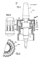
- FIGS. 1 to 6 shows a metering device 11 in the form of a pump atomizer, which is screwed onto a container 12 shown in broken lines.
- This pump atomizer has a pump chamber 13, not shown in detail, into which liquid is sucked from the interior of the container via a suction hose 14 and, under the action of a piston running in the pump chamber 13, which is connected to a piston rod 15, outputs liquid sucked in via an atomizer nozzle 16 , which is arranged at the upper end of a slightly conical shaft 17.
- the shaft is part of a plastic component that forms an actuation push button 18 for actuating the pump. It has a wide shoulder 19 which surrounds the shaft 17 and forms an actuating surface for the user's fingers.
- a stepped jacket 20 projects downwards, which largely surrounds the inner parts of the pump atomizer.
- a ring 21 projects downward from the shoulder 19 and has an axial, i.e. carries vertically extending toothing 22 which engages with a corresponding toothing 23 of a pump base part 24 and forms an axial guide for the actuating pusher, i.e. axial movement allowed, but rotation prevented.
- the base part like all the other parts of the atomizer pump described, is made of injection molded plastic and has a triple graduated, tapering sleeve shape. In the middle area there is the internal fastening thread 25 for screwing onto the container 12.
- the outside of the middle step of the cover part 24 is surrounded by a counting ring 26, which is axially fixed on the cover part 24 by snapping an annular projection 27 into an annular groove, but is rotatable is.
- the counting ring 26 is slightly worn on the outside, in a lower one outside projecting area of its casing characters 28, for example a consecutive numbering that corresponds to the number of the actuation stroke that the atomizer pump is to perform (FIG. 6).
- the counting ring has essentially axially extending ribs 29 on the outside, which belong to a relay device 30 and are arranged around the entire circumference.
- the ribs 29 have beveled buttons 31 on their free upper side (FIG. 2), to which correspondingly beveled buttons 32 on inner ribs 33 in the actuation button are assigned. From Fig. 2 it can be seen that the number of ribs 29 is twice as large as that of the ribs 33rd
- a ratchet 35 also belongs to the indexing device 30 (FIG. 4). It consists of a locking star 36 in the form of an external toothing of the base part 24, with which four resilient plastic tabs 37 of the counting ring 26 cooperate.
- the plastic tabs work with the locking star in the manner of ratchet pawls.
- the shape of the toothing which consists of relatively flat inclined tooth flanks with an asymmetrical incision on the tooth base, ensures that the obliquely arranged plastic tabs automatically rotate the counting ring 26 into the position shown in FIG. 4 by their own spring, and also from one position position rotated by a few degrees compared to the position shown.
- the counting ring can rotate clockwise, but is prevented from rotating by the plastic tabs counterclockwise.
- An additional ring 38 is rotatably mounted on the base part, which can be moved axially upwards by hand and is then coupled into the counting ring 26 by means of a corresponding toothing, so that it rotates together with the counting ring.
- This ring can also bear a label 39, for example in the form of the days of the week (FIG. 6).
- the respectively valid character 28 on the counter ring 26 can be identified by any identification on the actuating button, but preferably by a window-like cutout 40 in the casing 20.
- the actuating button 18 is secured against the counting ring 26 against being pulled upwards by a resilient snap-in nose 41.
- the counting ring 26 has on its upper inner side an inwardly projecting projection 42, which lies in the circumferential path of a corresponding projection 43 of the actuating button 18.
- the projections are dimensioned in relation to one another in such a way that, if they do not work together, they do not hinder the axial movement of the actuating button 18 relative to the counting ring 26 or the base part 24, but the position shown in FIG. 3, in which a shoulder 44 of the projection 42 cooperates with the projection 43, prevent the axial movement.
- a stop 45 of the projection 42 which extends upwards over the shoulder 44 prevents further rotation of the counting ring beyond the locking position shown in FIG.
- the stops 42, 43 thus form a lock for the actuation stroke of the atomizer pump.
- a transport lock 46 is provided which, when the actuating position 18 is rotated relative to the actuating position shown in Fig. 5, becomes effective in the clockwise direction and prevents actuation.
- the teeth of the toothing 22 on the actuating pushers move overcoming a hump-like projection 47 into a position in which they no longer run in the groove 48 corresponding to them, but are prevented from axial movement by a locking surface 49.
- the hump-like projections secure the corresponding transport and operating position against accidental rotation.
- the metering device 11 is normally fixedly mounted on the container 12, which is filled with the corresponding amount of a substance to be dispensed. It can be a liquid, but it can also be other flowable substances up to a paste or cream form; which are then not atomized, but are only dispensed at an outlet opening. It is ensured that the pump chamber is already filled, so that dispensing takes place during the first actuation stroke. However, it would also be possible to deliberately provide an initial intake stroke before the actual counting begins.
- the atomizer pump is secured for transport in that 5 shown position of the actuating button 18 is pivoted somewhat clockwise, so that its teeth or ribs 22 are above the locking surface 4 9.
- the actuation lever is pivoted counterclockwise and is then in the position that can be seen in FIG. 5.
- the container For example, filled with a pharmaceutical that is absorbed through the nasal mucosa, the shaft 17 is inserted into a nasal cavity and the pump is actuated by pressure on the shoulder 19.
- the ribs 22 run in the grooves 48 and do not hinder the axial movement during the actuation stroke, but secure the actuation pusher against rotation.
- the additional ring had been shifted upwards from the position shown in FIG. 1, specifically to a position in which the inscriptions 28, 39 match each other (for example, date and day of the week).
- This cycle is repeated until the projections 42 and 43 are in the position shown in FIG. 3. This is done after a number of actuation strokes that correspond to the cycle of use. With a three-week period of use, for example, this position would be reached after the 21st stroke and the pump would be blocked against further use. Since in the embodiment shown no handle is shown to reset the pump, the service life would have ended. Accidental further rotation is prevented by the stop 45. With a pharmaceutical zeuti.kum, the use of which should be repeated after a certain time, however, the stop 45 could be missing and instead a strong rest could be provided, which could be overridden by manually rotating the handle 26 provided with a handle, so that the cycle of use could then begin again .
- FIGS. Another embodiment is shown in FIGS.
- the same parts have the same reference numerals, which are supplemented by the index "a” for similar parts. Because of their detailed description, reference is made to the above to avoid repetition.
- the jacket 20a of the actuating button 18a and the counting ring 26a are made axially shorter.
- the ribs 29a on the counting ring 26a have a stronger design in the radial direction and, in addition to the continuation ribs 33 designed as individual free-standing axially extending webs, cooperate on their outer circumference with detent springs 37a which are shaped as leaf spring-like strips and are formed by axially extending incisions in the casing 20a .
- the number of these plastic spring clips 37a corresponds to the number of ribs 29a, so that they thereby form a locking mechanism 35a.
- This version is particularly simple. In the illustrated embodiment, however, there is no protection against reverse rotation. However, this could be done by an asymmetrical design of the plastic spring tabs 37a. Like the ratchet 35 in the embodiment according to FIGS. 1 to 6, the ratchet 35a also takes over the task of advancing to a defined rotational position with each stroke. To achieve a good spring action is inside half of these tabs a puncture that separates them from the ribs 33. This embodiment has no additional ring with otherwise the same design.
Abstract
Description
Die Erfindung betrifft eine betätigbare Dosiereinrichtung mit einem Betätigungsdrücker zur Ausgabe einer Mengeneinheit eines fließfähigen Stoffes bei jedem Betätigungshub aus einem Behälter, insbesondere eine Dosier- oder Zerstäuberpumpe.The invention relates to an actuatable metering device with an actuating button for dispensing a unit of quantity of a flowable substance with each actuation stroke from a container, in particular a metering or atomizing pump.
Derartige Dosiereinrichtungen werden für die verschiedensten Anwendungszwecke und Ausgabematerialien verwendet, unter anderem auch für medizinische Zwecke. Es kann sich dabei um Dosier- oder Zerstäuberpumpen handeln, die bei jedem Pumpenhub eine Mengeneinheit des Materials fördern und ausgeben sowie ggf. zerstäuben. Es können jedoch als Dosiereinrichtung auch Dosierventile benutzt werden, die an Behälter mit einem Innendruck angebracht sind und bei Betätigung zur Ausgabe einer bestimmten Menge öffnen und danach wieder schließen.Such metering devices are used for a wide variety of applications and dispensing materials, including medical purposes. These can be metering or atomizing pumps, which convey and dispense a quantity unit of material with each pump stroke, and atomize if necessary. However, metering valves can also be used as metering devices, which are attached to containers with an internal pressure and open when actuated to dispense a certain amount and then close again.
Die bei einem Betätigungshub ausgegebenen Mengeneinheiten können bei geeigneter Ausbildung der Dosiereinrichtung in relativ engen Grenzen konstant gehalten werden, sodaß auch eine Dosierung von solchen Pharmazeutika möglich ist, deren Wirkung von der Dosierung abhängig ist. Es läßt sich jedoch bisher nicht vermeiden, daß versehentlich durch eine zu geringe oder zu große Zahl von Betätigungshüben unter- bzw. überdosiert wurde oder die Anwendung über eine zu lange Zeit oder in der falschen Aufeinanderfolge erfolgte.The quantity units output during an actuation stroke can be kept constant within relatively narrow limits with a suitable design of the metering device, so that metering of such pharmaceuticals is also possible. the effect of which depends on the dosage. However, it has so far not been possible to avoid inadvertently underdosing or overdosing due to a too small or too large number of actuation strokes or that the application has been carried out for too long a time or in the wrong sequence.
Aufgabe der Erfindung ist es, eine betätigbare Dosiereinrichtung zu schaffen, mit der die Überwachung der genauen Dosierung möglich ist, bzw eine Fehldosierung in Bezug auf Zahl und/oder Zeitdauer weitgehend ausgeschlossen ist.The object of the invention is to provide an actuatable metering device with which the exact metering can be monitored or an incorrect metering in terms of number and / or duration is largely excluded.
Diese Aufgabe wird gemäß der Erfindung durch eine Zähleinrichtung für die Betätigungshübe gelöst.This object is achieved according to the invention by a counting device for the actuation strokes.
Die Zähleinrichtung wird also von der Betätigung des Betätigungsdrückers ausgelöst und kann in verschiedenartiger Weise ausgebildet sein. Sie kann beispielsweise eine optische Anzeige enthalten, die die Zahl der Betätigungshübe anzeigt. Dazu kann bei einer vorteilhaften Ausführungsform der Erfindung die Zähleinrichtung einen drehbaren Zählring, vorzugsweise mit einer Skalierung, enthalten. Ferner kann ein Zusatzring vorgesehen sein, der vorzugsweise durch Axialverschiebung in den Zählring einkuppelbar ist. Durch diesen Zusatzring kann zusätzlich zu einer Zahl eine zweite Skalierung vorgesehen sein, beispielweise zusätzlich zu einer Datumsfolge einer Wochentagsfolge. Es ist somit möglich, daß beispielsweise durch den Zählring bei einer täglich einmaligen Anwendung über eine bestimmte Anzahl von Tagen der Zählring diese Tagesanzahl zählt, während der Zusatzring den jeweils zugehörigen Wochentag anzeigt, sodaß der Anwender jeweils auch feststellen kann, ob er an dem betreffenden Tag die Anwendung schon vorgenommen hat oder nicht.The counting device is thus triggered by the actuation of the actuation button and can be designed in various ways. For example, it can contain an optical display which shows the number of actuation strokes. For this purpose, in an advantageous embodiment of the invention, the counting device can contain a rotatable counting ring, preferably with a scale. Furthermore, an additional ring can be provided, which can preferably be coupled into the counting ring by axial displacement. With this additional ring, a second scaling can be provided in addition to a number, for example in addition to a date sequence of a weekday sequence. It is therefore possible that, for example, the counting ring counts this number of days for a certain number of days during a single application, while the additional ring shows the associated weekday, so that the user can also determine whether he is on the relevant day has already done the application or not.
Besonders bevorzugt ist eine Ausführung mit einer in Abhängigkeit von der Zähleinrichtung betätigbaren Sperre für den Betätigungshub. Hier kann beispielsweise bei einer beabsichtigten Beendigung der Anwendungsdauer nach einer bestimmten Anzahl von Betätigungshüben (oder beispielsweise Tagen ) die Dosiereinrichtung blockiert werden, um eine zeitliche 0berdosierung zu vermeiden. Auf diese Weise ist es möglich, auch sehr dosierungsabhängige Pharmazeutika in Form von Sprays zu verwenden, bei denen eine genaue Folge von Anwendungstagen einer entsprechenden Zahl von Anwendungspausen gegenüberstehen muß.An embodiment with a lock for the actuation stroke that can be actuated as a function of the counting device is particularly preferred. Here, for example, if the intended duration of use ends after a certain number of actuation strokes (or days, for example), the metering device can be blocked in order to avoid overdosing over time. In this way it is possible to use very dose-dependent pharmaceuticals in the form of sprays, in which an exact sequence of days of use must be offset by a corresponding number of breaks in use.
Außerdem ist es jedoch möglich, auf diese Weise veränderliche Dosierungen einfach und sinnfällig vorzunehmen, indem diese unterschiedliche Dosierung durch eine entsprechende Skalierung und/oder Sperren, die ggf. auch lösbar sein können, vorgegeben wird. So kann die Dosiereinrichtung bereits für eine im Laufe der Behandlungsdauer abnehmende Dosierung vorgesehen sein. Das Vorsehen einer lösbaren Sperre ermöglicht die Anwendung ohne die Notwendigkeit des Mitzählens beim Anwender, indem beispielsweise die Sperre bei einer täglichen Maximaldosierung von einer gewissen Anzahl von Hüben wirksam wird, dann aber wieder gelöst werden kann.In addition, however, it is possible to carry out variable doses in a simple and sensible manner in that this different dosing is predetermined by appropriate scaling and / or locking, which may also be able to be solved. Thus, the dosing device can already be provided for a dosing that decreases over the course of the treatment period. The provision of a releasable lock enables use without the need for counting by the user, for example by the lock becoming effective with a daily maximum dosage of a certain number of strokes, but then being able to be released again.
Eine besonders einfache und vorteilhafte Ausführungsform einer Dosierungseinrichtung, die sich mit einer üblichen kleinen Hand-Zerstäuberpumpe konstuktiv vereinigen läßt, ist vorzugsweise derart ausgebildet, daß die Dosierungseinrichtung einen Basisteil, den axial dazu beweglich gelagerten Betätigungsdrücker und einen den Basisteil umgebenen Zählring aufweist, wobei zwischen dem Betätigungsdrücker und dem Zählring eine bei Axialverschiebung schrittweise arbeitende Weiterschalteinrichtung vorgesehen ist.A particularly simple and advantageous embodiment of a metering device which can be combined constructively with a conventional small hand-held atomizer pump is preferably designed in such a way that the metering device has a base part, the actuating pusher which is mounted so as to be axially movable thereto and a surrounding part of the base part Has counting ring, a step-by-step device operating step-wise with axial displacement being provided between the actuating button and the counting ring.
Vorteilhaft kann der Betätigungsdrücker mit dem Basisteil drehfest, aber axial verschieblich verbunden sein. Die Weiterschalteinrichtung kann abgeschrägte Schaltflächen und ein vorzugsweise einseitig wirkendes Gesperre enthalten. Durch die abgeschrägten Schaltflächen wird der Weitertransport des Zählringes vorgenommen und das Gesperre verhindert eine unzulässige Rückdrehung. Vorteilhaft ist das Gesperre gleichzeitig als eine gewisse federnde Hemmung zum Verhindern einer unbeabsichtigten Weiterdrehung ausgerichtet. Hier könnte jedoch auch eine Weiterschalteinrichtung Verwendung finden, bei der eine formschlüßige Sperrung gegen Weiterdrehung vorliegt.The actuating pusher can advantageously be connected to the base part in a rotationally fixed but axially displaceable manner. The relaying device can contain beveled buttons and a preferably one-way locking mechanism. Due to the beveled buttons, the counter ring is transported further and the locking mechanism prevents an impermissible reverse rotation. At the same time, the locking mechanism is advantageously designed as a certain resilient inhibition to prevent unintentional further rotation. Here, however, a step-by-step device could also be used, in which there is a positive locking against further rotation.
Das Gesperre kann eire Einrasteinrichtung aufweisen, die den Zählring jeweils nach Oberschreiten einer vorgegebenen Drehstellung jeweils in eine bestimmte Lage weiterdreht. Hierbei braucht also die Weiterschalteinrichtung nicht den vollen Schaltweg durchzuführen, sondern die Weiterdrehung in die jeweilige Endlage wird durch die Einrasteinrichtung bewirkt und dort bis zur nächsten Betätigung fixiert.The locking mechanism can have a snap-in device, which rotates the counting ring into a specific position each time a predetermined rotational position is exceeded. In this case, the indexing device does not need to carry out the full switching path, but the further rotation into the respective end position is effected by the snap-in device and fixed there until the next actuation.
Die Sperre für den Betätigungshub kann durch zusammenwirkende Vorsprünge bzw. Flächen an Betätigungsdrücker und Zählring ausgebildet sein. Wenn der Zählring also seine vorgegebene Endlage erreicht hat, wird die Sperre wirksam und der Betätigungshub verhindert. Bei einer lösbaren Sperre könnte am Zählring eine Handhabe sein, mit der erineineneue Ausgangslage gedreht werden kann.The lock for the actuation stroke can be formed by cooperating projections or surfaces on the actuation push button and counting ring. When the counting ring has reached its specified end position, the lock becomes effective and the actuation stroke is prevented. In the case of a releasable lock, there could be a handle on the counting ring with which a new starting position can be turned.
Merkmale von bevorzugten Weiterbildungen der Erfindung gehen aus den Unteransprüchen und der Beschreibung im Zusammenhang mit den Zeichnungen hervor, wobei die einzelnen Merkmale jeweils für sich allein oder zu mehreren in Form von Unterkombinationen bei einer Ausführungsform der Erfindung verwirklicht sein können. Ausführungsbeispiele der Erfindung sind in der Zeichnung dargestellt und werden im folgenden näher erläutert. In der Zeichnung zeigen:
- Fig. 1 einen vertikalen Teilschnitt durch eine.. Zerstäuberpumpe,
- Fig. 2 Teilschnitt nach der Linie II in Fig. 1,
- Fig. 3 einen Teilschnitt nach der Linie III in Fig. 1,
- Fig. 4 einen horizontalen Schnitt nach der Linie IV (ohne Pumpeninnenteil),
- Fig. 5 einen horizontalen Teilschnitt nach der Linie V in Fig. 1 (ebenfalls ohne Pumpeninnenteil),
- Fig. 6 eine Seitenansicht der Zerstäuberpumpe nach Fig. 1,
- Fig. 7 einen vertikalen Teilschnitt durch eine andere Ausführungsform,
- Fig. 8 einen Detailschnitt nach der Linie VIII und
- Fig. 9 einen horizontalen Detailschnitt nach der Linie IX (ohne Pumpeninnenteil).
- 1 is a partial vertical section through an atomizer pump,
- 2 partial section along the line II in Fig. 1,
- 3 shows a partial section along the line III in FIG. 1,
- 4 shows a horizontal section along line IV (without inner pump part),
- 5 is a partial horizontal section along the line V in Fig. 1 (also without inner pump part),
- 6 is a side view of the atomizer pump of FIG. 1,
- 7 is a partial vertical section through another embodiment,
- Fig. 8 shows a detail section along the line VIII and
- Fig. 9 shows a horizontal detail section along the line IX (without inner pump part).
Die Ausführungsform nach den Fig. 1 bis 6 zeigt eine Dosiereinrichtung 11 in Form eines Pumpenzerstäubers, der auf einen strichpunktiert gezeichneten Behälter 12 aufgeschraubt ist. Dieser Pumpenzerstäuber hat eine im einzelnen nicht dargestellte Pumpenkammer 13, in die über einen Saugschlauch 14 Flüssigkeit aus dem Behälterinneren angesaugt wird und unter der Wirkung eines in der Pumpenkammer 13 laufenden Kolbens, der mit einer Kolbenstange 15 verbunden ist, angesaugte Flüssigkeit über eine Zerstäuberdüse 16 ausgibt, die am oberen Ende eines leicht konischen Schaftes 17 angeordnet ist. Der Schaft gehört zu einem Kunststoff-Bauteil, das einen Betätigungsdrücker 18 zur Betätigung der Pumpe bildet. Er hat eine breite Schulter 19, die den Schaft 17 umgibt und eine Betätigungsfläche für die Finger des Benutzers bildet. Von dort aus ragt ein stufig abgesetzter Mantel 20 abwärts, der die inneren Teile des Pumpenzerstäubers weitgehend umgibt. Von der Schulter 19 ragt ein Ring 21 abwärts, der an seiner Innenseite eine axial, d.h. vertikal verlaufende Verzahnung 22 trägt, die mit einer entsprechenden Verzahnung 23 eines Pumpen- Basisteils 24 in Eingriff ist und eine Axialführung für den Betätigungsdrücker bildet, d.h. axiale Bewegungen erlaubt, jedoch Drehbewegungen verhindert.The embodiment according to FIGS. 1 to 6 shows a
Das Basisteil besteht, wie alle übrigen beschriebenen Teile der Zerstäuberpumpe, aus Kunststoffspritzguß und hat eine dreifach abgestufte, sich nach oben verjüngende Hülsenform. Im mittleren Bereich befindet sich das Befestiguns-Innengewinde 25 zum Aufschrauben auf den Behälter 12. Die Außenseite der mittleren Stufe des Deckelteils 24 ist von einem Zählring 26 umgeben, der an dem Deckelteil 24 durch Einschnappen eines Ringvorsprunges 27 in eine Ringnut axial festgelegt, jedoch drehbar ist. Der Zählring 26 trägt an seiner Außenseite, in einem unteren, etwas nach außen vorspringenden Bereich seines Mantels Schriftzeichen 28, beispielsweise eine fortlaufende Nummerierung, die der Zahl der Betätigungshube entspricht, die die Zerstäuberpumpe ausführen soll (Fig. 6). Im oberen Teil hat der Zählring an der Außenseite im wesentlichen axial verlaufende Rippen 29, die zu einer Weiterschalteinrichtung 30 gehören und um den gesamten Umfang herum angeordnet sind. Die Rippen 29 haben an ihrer freien Oberseite abgeschrägte Schaltflächen 31 (Fig. 2), denen in entsprechender Weise abgeschrägte Schaltflächen 32 an inneren Rippen 33 im Betätigungsdrücker zugeordnet sind. Aus Fig. 2 ist zu erkennen, daß die Zahl der Rippen 29 doppelt so groß ist, wie die der Rippen 33.The base part, like all the other parts of the atomizer pump described, is made of injection molded plastic and has a triple graduated, tapering sleeve shape. In the middle area there is the
Ebenfalls zur Weiterschalteinrichtung 30 gehört ein Gesperre 35 (Fig. 4). Es besteht aus einem Raststern 36 in Form einer äußeren Verzahnung des Basisteils 24, mit dem vier federnde Kunststofflaschen 37 des Zählringes 26 zusammenwirken. Die Kunststofflaschen arbeiten mit dem Raststern nach Art von Schaltklinken zusammen. Durch die Form der Verzahnung, die aus relativ flach geneigten Zahnflanken mit einem unsymmetrischen Einschnitt am Zahngrund besteht, ist sichergestellt, daß die schräg angeordneten Kunststofflaschen durch ihre Eigenfederung den Zählring 26 selbsttätig in die in Fig. 4 dargestellte Position drehen, und zwar auch aus einer gegenüber der dargestellten Lage um einige Grad verdrehten Stellung. Der Zählring kann sich im Uhrzeigersinn drehen, wird jedoch entgegen dem Uhrzeigersinn an einer Drehung durch die Kunststofflaschen gehindert. Auf dem Basisteil ist ferner ein Zusatzring 38 verdrehbar gelagert, der von Hand axial nach oben verschiebbar ist und dann durch eine entsprechende Verzahnung in den Zählring 26 eingekuppelt wird, sodaß er sich zusammen mit dem Zählring dreht. Auch dieser Ring kann eine Beschriftung 39 tragen, zum Beispiel in Form der Wochentage (Fig. 6). Das jeweils gültige Schriftzeichen 28 auf dem Zählring 26 kann durch eine beliebige Kennzeichnung an dem Betätigungsdrücker bezeichnet sein, vorzugsweise jedoch durch einen fensterartigen Ausschnitt 40 im Mantel 20.A
Der Betätigungsdrücker 18 ist gegenüber dem Zählring 26 gegen Abziehen nach oben durch eine federnde Schnapp-Rastnase 41 gesichert.The
Der Zählring 26 hat an seiner oberen Innenseite einen nach innen ragenden Vorsprung 42, der in der Umfangsbahn eines entsprechenden Vorsprunges 43 des Betätigungsdrückers 18 liegt. Die Vorsprünge sind in Axialrichtung so zueinander bemessen, daß sie, wenn sie nicht zusammenarbeiten, die Axialbewegung des Betätigungsdrücker 18 gegenüber dem Zählring 26 bzw. dem Basisteil 24 nicht behindern, jedoch der in Fig. 3 dargestellten Lage, in der ein Absatz 44 des Vorsprunges 42 mit dem Vorsprung 43 zusammenwirkt, die Axialbewegung verhindern. Ein über den Absatz 44 nach oben reichender Anschlag 45 des Vorsprunges 42 verhindert eine weitere Drehung des Zählringes über die in Fig.3 gezeigte Sperrstellung hinaus. Die Anschläge 42, 43 bilden also eine Sperre für den Betätigungshub der Zerstäuberpumpe.The
Aus Fig. 5 ist zusätzlich noch zu erkennen, daß eine Transportsicherung 46 vorgesehen ist, die bei einer der gegerüber Fig. 5 dargestellten Betätigungsstellung vorgenommenenVerdrehung des Betätigungsdrückers 18 gegenüber dem Basisteil im Uhrzeigersinne wirksam wird und eine Betätigung verhindert. Dabei verschieben sich die Zähne der Verzahnung 22 am Betätigungsdrücker unter überwindung eines buckelartigen Vorsprunges 47 in eine Stellung, in der sie nicht mehr in der ihnen entsprechende Nut 48 laufen, sondern von einer Sperrfläche 49 an einer Axialbewegung gehindert werden. Die buckelartigen Vorsprünge sichern die entsprechende Transport- und Betätigungsstellung gegen versehentliche Verdrehung.From Fig. 5 it can also be seen that a
Die Funktion der Ausführungsform nach den Fig. 1 bis 6 ist wie folgt: die Dosiereinrichtung 11 ist normalerweise fest auf dem Behälter 12 montiert, der mit der entsprechenden Menge eines auszugebenden Stoffes gefüllt ist. Es kann sich dabei um Flüssigkeit handeln, jedoch auch um andere fließfähige Stoffe bis zur Brei- oder Cremeform; die dann nicht zerstäubt, sondern lediglich an einer Auslaßöffnung ausgegeben werden. Es wird dafür gesorgt, daß die Pumpenkammer bereits gefüllt ist, sodaß schon beim ersten Betätgungshub eine Ausgabe erfolgt. Es wäre jedoch auch möglich, bewußt eine anfängliche Ansaug-Hübe vorzusehen, bevor die eigentliche Zählung beginnt.The function of the embodiment according to FIGS. 1 to 6 is as follows: the
Zum Transport ist die Zerstäuberpumpe dadurch gesichert, daß gegenüberderinFig. 5 gezeigten Stellung der Betätigungsdrücker 18 etwas im Uhrzeigersinne verschwenkt ist, sodaß seine Verzahnung oder Rippen 22 über der Sperrfläche 49 stehen. Zu Inbetriebnahme wird der Betätigungsdrücker entgegen dem Uhrzeigersinn verschwenkt und steht dann in der Stellung, die aus Fig. 5 ersichtlich ist. Wenn der Behälter beispielweise mit einem Pharmazeutikum gefüllt ist, das über die Nasenschleimhäute aufgenommen wird, so wird der Schaft 17 in eine Nasenhöhle eingeführt und die Pumpe durch Druck auf die Schulter 19 betätigt. Die Rippen 22 laufen dabei in den Nuten 48 und behindern die Axialbewegung während des Betätigungshubes nicht, sichern den Betätigungsdrücker jedoch gegen Verdrehung. Gleichzeitig kamen jedoch die Schrägflächen 31, 32 der Rippen 29. 33 miteinander in Eingriff und transportierten den Zählring 26 in Fig.2 nach links, und zwar um eine Stecken, die etwas geringer ist, als der Abstand zwischen den Rippen 29. Dabei werden auch die Kunststofflaschen 37 jeweils über die Scheitel des an sie angrenzenden Zahns des Raststerns 36 transportiert. Beim Rückwärtshub nach erfolgter Zerstäubung des auszugebenden Stoffes durch die Zerstäuberdüse 16 kommen die beiden Rippen 29, 33 wieder außer Eingriff und die Kunststofflaschen 37 laufen auf den schrägen Zahnflanken abwärts und drehen den Raststern weiter in eine Lage entsprechend Fig. 4. In dieser Lage steht dann die nächstfolgende Zahl 28 und die nächstfolgende Beschriftung 39 auf dem Zusatzring 38 im Bereich des Fensters 40.The atomizer pump is secured for transport in that 5 shown position of the
Der Zusatzring war gegenüber der in Fig. 1 gezeigten Stellung aufwärts verschoben worden, und zwar in eine Stellung, in der die Beschriftunaen28 ,39 zueinander passen (beispielsweise Datum und Wochentag).The additional ring had been shifted upwards from the position shown in FIG. 1, specifically to a position in which the
Dieser Zyklus wiederholt sich solange bis die Vorsprünge 42 und 43 sich in der Lage nach Fig. 3 befinden. Dies erfolgt nach einer Zahl von Betätigungshüben, die dem Benutzungszyklus entspricht. Bei einer dreiwöchigen Benutzungsdauer würde beispielsweise nach dem 21. Hub diese Stellung erreicht sein und die Pumpe wäre gegen weitere Benutzung gesperrt. Da bei der gezeigten Ausführungsform keine Handhabe gezeigt ist, um die Pumpe wieder zurückzustellen, wäre damit die Benutzungsdauer beendet. Eine versehentliche Weiterdrehuno wird durch den Anschlag 45 verhindert. Bei einem Pharma- zeuti.kum, dessen Verwendung nach einer bestimmten Zeit wiederholt werden sollte, könnte jedoch der Anschlag 45 fehlen und stattdessen eine kräftige Rast vorgesehen sein, die durch manuelle Verdrehung des mit einer Handhabe versehenen Zählringes 26 überfahren werden könnte, sodaß dann der Benutzungszyklus erneut beginnen könnte.This cycle is repeated until the
In den Fig. 7 bis 9 ist eine andere Ausführungsform gezeigt. In diesen Figuren tragen gleiche Teile gleiche Bezugszeichen, die bei ähnlichen Teilen durch den Index "a" ergänzt sind. Wegen ihrer Beschreibung im einzelnen wird zur Vermeidung von Wiederholung auf das Vorstehende Bezug genommen.Another embodiment is shown in FIGS. In these figures, the same parts have the same reference numerals, which are supplemented by the index "a" for similar parts. Because of their detailed description, reference is made to the above to avoid repetition.
Bei dieser Ausführung sind der Mantel 20a des Betätigungsdrückers 18a und der Zählring 26a axial kürzer ausgeführt. Die Rippen 29a am Zählring 26a sind in radialer Richtung stärker ausgeführt und arbeiten außer mit den als einzelne freistehende axial verlaufende Stege ausgebildeten Weiterschalterippen 33 an ihrem Außenumfang mit Rastfedern 37a zusammen, die als blattfederartige Streifen geformt sind und durch axial verlaufende Einschnitte im Mantel 20a gebildet sind. Die Zahl dieser Kunststoff-Federlaschen 37a entspricht der Zahl der Rippen 29a, sodaß sie dadurch ein Gesperre 35a bilden.In this embodiment, the
Diese Ausführung ist besonders einfach. In der dargestellten Ausführungsform ist jedoch keine Sicherung gegen Rückdrehung vorhanden. Dies könnte jedoch durch eine unsymmetrische Gestaltung der Kunststoff-Federlaschen 37a geschehen. Wie das Gesperre 35 bei der Ausführungsform nach Fig. 1 bis 6 übernimmt auch das Gesperre 35a die Aufgabe der Weiterschaltung bis in eine definierte Drehstellung bei jedem Hub. Zum Erreichen einer guten Federwirkung befindet sich innerhalb dieser Laschen ein Einstich, der sie von den Rippen 33 trennt. Diese Ausführungsform hat bei im Übrigen gleicher Gestaltung keinen Zusatzring.This version is particularly simple. In the illustrated embodiment, however, there is no protection against reverse rotation. However, this could be done by an asymmetrical design of the
Claims (10)
Priority Applications (1)
| Application Number | Priority Date | Filing Date | Title |
|---|---|---|---|
| AT84100254T ATE41613T1 (en) | 1983-01-22 | 1984-01-12 | ACTUABLE DOSING DEVICE. |
Applications Claiming Priority (2)
| Application Number | Priority Date | Filing Date | Title |
|---|---|---|---|
| DE3302160A DE3302160A1 (en) | 1983-01-22 | 1983-01-22 | OPERATING DOSING DEVICE |
| DE3302160 | 1983-01-22 |
Publications (3)
| Publication Number | Publication Date |
|---|---|
| EP0114617A2 true EP0114617A2 (en) | 1984-08-01 |
| EP0114617A3 EP0114617A3 (en) | 1985-10-09 |
| EP0114617B1 EP0114617B1 (en) | 1989-03-22 |
Family
ID=6189009
Family Applications (1)
| Application Number | Title | Priority Date | Filing Date |
|---|---|---|---|
| EP84100254A Expired EP0114617B1 (en) | 1983-01-22 | 1984-01-12 | Manually operable dosage device |
Country Status (6)
| Country | Link |
|---|---|
| US (1) | US4565302A (en) |
| EP (1) | EP0114617B1 (en) |
| JP (1) | JPH0818629B2 (en) |
| AT (1) | ATE41613T1 (en) |
| DE (2) | DE3302160A1 (en) |
| ES (1) | ES8500173A1 (en) |
Cited By (26)
| Publication number | Priority date | Publication date | Assignee | Title |
|---|---|---|---|---|
| DE4027670A1 (en) * | 1990-08-31 | 1992-03-05 | Pfeiffer Erich Gmbh & Co Kg | DISCHARGE DEVICE FOR MEDIA |
| EP0709142A1 (en) | 1994-10-27 | 1996-05-01 | Ing. Erich Pfeiffer Gmbh | Fluid dispenser |
| DE19549033C1 (en) * | 1995-12-28 | 1997-05-28 | Boehringer Ingelheim Int | Mechanical counter for a dosing device |
| EP0950423A2 (en) | 1998-04-18 | 1999-10-20 | Ing. Erich Pfeiffer GmbH | Product dispenser, especially for powder |
| WO2001003851A1 (en) * | 1999-07-12 | 2001-01-18 | Astrazeneca Ab | Delivery device |
| DE3645354C2 (en) * | 1985-09-14 | 2003-05-08 | Pfeiffer Erich Gmbh & Co Kg | Disposable medicament sprayer discharge mechanism |
| US6729330B2 (en) | 1998-05-05 | 2004-05-04 | Trudell Medical International | Indicating device for aerosol container |
| US6745760B2 (en) | 2001-05-15 | 2004-06-08 | Trudell Medical International | Medicament applicator |
| US6761161B2 (en) | 1998-05-05 | 2004-07-13 | Trudell Medical International | Indicating device |
| EP1695922A1 (en) * | 2003-12-12 | 2006-08-30 | Taisho Pharmaceutical Co. Ltd. | Small fixed quantity dispenser for aerosol container |
| US7743945B2 (en) | 2005-01-20 | 2010-06-29 | Trudell Medical International | Dispensing device |
| US7984826B2 (en) | 1998-01-16 | 2011-07-26 | Trudell Medical International | Indicating device |
| US8074594B2 (en) | 2003-12-15 | 2011-12-13 | Trudell Medical International | Dose indicating device |
| US8079362B2 (en) | 2004-09-20 | 2011-12-20 | Trudell Medical International | Method for displaying dosage indicia |
| US8082873B2 (en) | 2008-05-05 | 2011-12-27 | Trudell Medical International | Drive mechanism for an indicating device |
| US8141550B2 (en) | 2006-08-01 | 2012-03-27 | Trudell Medical International | Dispensing device |
| US8181591B1 (en) | 2008-05-23 | 2012-05-22 | Trudell Medical International | Domed actuator for indicating device |
| US8327847B2 (en) | 2002-03-21 | 2012-12-11 | Trudell Medical International | Indicating device for aerosol container |
| WO2013113899A1 (en) * | 2012-02-02 | 2013-08-08 | Soerensen Bjoern O | Device for delivering a metering aerosol |
| US8578934B2 (en) | 2003-10-28 | 2013-11-12 | Trudell Medical International | Indicating device with warning dosage indicator |
| US8596265B2 (en) | 2008-10-22 | 2013-12-03 | Trudell Medical International | Modular aerosol delivery system |
| EP2692328A1 (en) * | 2012-08-03 | 2014-02-05 | Becton Dickinson France | Dose counting device for coupling with a medical container |
| WO2017021296A1 (en) * | 2015-07-31 | 2017-02-09 | Sulzer Mixpac Ag | Child-resistant discharger |
| EP1633421B1 (en) | 2003-05-15 | 2020-03-04 | Aptar France SAS | Fluid product dispenser |
| EP3884976A1 (en) * | 2017-07-21 | 2021-09-29 | Boehringer Ingelheim International GmbH | Nebulizer |
| FR3111625A1 (en) * | 2020-06-22 | 2021-12-24 | Aptar France Sas | Fluid dispenser device |
Families Citing this family (76)
| Publication number | Priority date | Publication date | Assignee | Title |
|---|---|---|---|---|
| DK481884D0 (en) * | 1984-10-09 | 1984-10-09 | Karl Holm | MEDICAL ORAL OR SWALLOW SPRAY APPLIANCES |
| DE3544985A1 (en) * | 1985-12-19 | 1987-06-25 | Pfeiffer Erich Gmbh & Co Kg | DISCHARGE DEVICE FOR FLOWABLE MEDIA |
| EP0254391A1 (en) * | 1986-04-25 | 1988-01-27 | Glaxo Group Limited | Indicating device for aerosol dispensers |
| FR2606506B1 (en) * | 1986-11-06 | 1992-12-31 | Valois | MEASURING VAPORIZER DEVICE PROVIDED WITH A MEANS FOR COUNTING EMITTED DOSES |
| US4944429A (en) * | 1987-08-28 | 1990-07-31 | Schering Corporation | Manually-operable spray dispenser with locking mechanism |
| FR2635214B1 (en) * | 1988-08-02 | 1993-02-12 | Union Pharma Scient Appl | DAILY DATE TUBE |
| US5718355A (en) * | 1989-02-03 | 1998-02-17 | Senetics, Inc. | Indicator device responsive to axial force for use with inhaler |
| US5421482A (en) * | 1989-02-03 | 1995-06-06 | Senetics, Inc. | Indicator device responsive to axial force |
| FR2651837B1 (en) * | 1989-09-08 | 1993-04-23 | Aerosol Inventions Dev | PRE-ORIENTABLE MANUAL PUMP ON THE CONE OF A CONTAINER. |
| US5301873A (en) * | 1990-03-26 | 1994-04-12 | Kold Ban International | Low fluid indicator for pressurized canister |
| DE4027669A1 (en) * | 1990-08-31 | 1992-03-05 | Pfeiffer Erich Gmbh & Co Kg | DISCHARGE DEVICE FOR MEDIA |
| EP0472915B2 (en) * | 1990-08-31 | 2002-03-20 | Ing. Erich Pfeiffer GmbH | Dispenser for fluid |
| DE4027672A1 (en) * | 1990-08-31 | 1992-03-05 | Pfeiffer Erich Gmbh & Co Kg | DISCHARGE DEVICE FOR MEDIA |
| DE4030530A1 (en) * | 1990-09-27 | 1992-04-02 | Pfeiffer Erich Gmbh & Co Kg | DISCHARGE DEVICE FOR MEDIA |
| IT1243820B (en) * | 1990-10-09 | 1994-06-28 | Elettro Plastica Spa | CONTADOSI DEVICE FOR DISPENSING DOSES OF FLUID PRODUCT, PARTICULARLY FOR PHARMACEUTICAL USE |
| US5243970A (en) * | 1991-04-15 | 1993-09-14 | Schering Corporation | Dosing device for administering metered amounts of powdered medicaments to patients |
| IT222834Z2 (en) * | 1991-07-23 | 1995-05-08 | Sandoz Prodotti Farmaceutici S | BUTTON-TYPE DOSING DEVICE WITH STROKE NUMBER COUNTER |
| PL173090B1 (en) * | 1992-12-18 | 1998-01-30 | Schering Corp | Powdered drug inhaler |
| FR2721106B1 (en) * | 1994-06-10 | 1996-09-13 | Step | Dose counter for inhalers. |
| US5624059A (en) * | 1995-04-05 | 1997-04-29 | Axys Environmental Systems Ltd. | Device for dispensing corrosive liquids accurately and without contamination |
| US5785048A (en) * | 1996-08-16 | 1998-07-28 | Koerner; Steve J. | Inhaler device with means for assessing its depletion level |
| DE19638508A1 (en) * | 1996-09-20 | 1998-03-26 | Meinrad Jungblut | Activity recorder for filling or removal of medium from container esp. for drugs |
| GB2320489A (en) | 1996-12-20 | 1998-06-24 | Norton Healthcare Ltd | Inhaler dose counter |
| US5860387A (en) * | 1997-05-30 | 1999-01-19 | Giveen; Samuel Charles | Automatic squeeze-bottle utilization cycle counting device |
| TW533865U (en) * | 1997-06-10 | 2003-05-21 | Glaxo Group Ltd | Dispenser for dispensing medicament and actuation indicating device |
| US6142339A (en) * | 1998-01-16 | 2000-11-07 | 1263152 Ontario Inc. | Aerosol dispensing device |
| US6336453B1 (en) | 1999-04-30 | 2002-01-08 | Trudell Medical International | Indicating device for aerosol container |
| DE29814647U1 (en) * | 1998-08-14 | 1999-12-23 | Wischerath Josef Gmbh Co Kg | Inhaler with a metering device |
| ATE232490T1 (en) * | 1999-03-23 | 2003-02-15 | Saint Gobain Calmar Sa | BOTTLE CAP |
| IT1312426B1 (en) | 1999-06-30 | 2002-04-17 | Microspray Delta Spa | DISPENSER OF DOSES OF A LIQUID, WITH A DEVICE FOR COUNTING A HIGH NUMBER OF DOSES DISPENSED |
| US6516799B1 (en) | 1999-09-08 | 2003-02-11 | Sapphire Design, Inc. | Inhalation counter device |
| DE19942792A1 (en) * | 1999-09-08 | 2001-03-15 | Pfeiffer Erich Gmbh & Co Kg | Media Donor |
| US6615827B2 (en) | 1999-09-08 | 2003-09-09 | Sapphire Designs, Inc. | Inhalation counter device |
| US6186364B1 (en) | 1999-11-22 | 2001-02-13 | Calmar Inc. | Dosage control for dispenser with child-resistant feature |
| DE10061723C2 (en) * | 2000-12-12 | 2003-01-16 | Eckert Rosemarie | Counter for counting metered deliveries of liquid, pasty or solid products as well as device for metered dispensing of such products |
| DE10065160A1 (en) | 2000-12-23 | 2002-06-27 | Pfeiffer Erich Gmbh & Co Kg | Device for detecting the actuation of a dispenser and dispenser |
| DE10159692A1 (en) * | 2001-11-29 | 2003-06-12 | Pfeiffer Erich Gmbh & Co Kg | metering |
| US6651844B2 (en) | 2002-02-22 | 2003-11-25 | Schering Corporation | Spray dispenser counter |
| JP4241613B2 (en) * | 2002-06-12 | 2009-03-18 | ベーリンガー インゲルハイム マイクロパーツ ゲゼルシャフト ミット ベシュレンクテル ハフツング | Counting device for counting metered delivery of liquid, pasty or solid products and device for metering and delivering such products |
| US7322352B2 (en) * | 2002-09-21 | 2008-01-29 | Aventis Pharma Limited | Inhaler |
| AU2002953483A0 (en) * | 2002-12-20 | 2003-01-09 | Acrux Dds Pty. Ltd. | Usage indicator |
| JP4262581B2 (en) * | 2003-11-25 | 2009-05-13 | 大正製薬株式会社 | Sub-quantitative dispensing device for aerosol containers |
| GB0328635D0 (en) * | 2003-12-10 | 2004-01-14 | 3M Innovative Properties Co | Dose counter for dispensers |
| US7378015B2 (en) * | 2003-12-18 | 2008-05-27 | The Clorox Company | Filtered water enhancements |
| US7713482B2 (en) | 2003-12-18 | 2010-05-11 | The Clorox Company | Control scheme for enhanced filtered water systems |
| US8556127B2 (en) * | 2004-05-24 | 2013-10-15 | Pur Water Purification Products, Inc. | Additive dispensing system for a refrigerator |
| US7670479B2 (en) * | 2004-05-24 | 2010-03-02 | PUR Water Purification, Inc. | Fluid container having an additive dispensing system |
| US8893927B2 (en) | 2004-05-24 | 2014-11-25 | Pur Water Purification Products, Inc. | Cartridge for an additive dispensing system |
| US20050258082A1 (en) * | 2004-05-24 | 2005-11-24 | Lund Mark T | Additive dispensing system and water filtration system |
| DE102005009294A1 (en) * | 2004-07-13 | 2006-02-16 | Ing. Erich Pfeiffer Gmbh | Donor for media |
| CA2576673C (en) * | 2004-08-12 | 2013-10-01 | Idec Corporation | Counter mechanism of feeding device and feeding device using such counter mechanism |
| JP4640795B2 (en) * | 2005-05-24 | 2011-03-02 | 大正製薬株式会社 | Liquid ejector |
| JP4688101B2 (en) * | 2005-05-24 | 2011-05-25 | 大正製薬株式会社 | Liquid ejector |
| JP4674752B2 (en) * | 2005-05-24 | 2011-04-20 | 大正製薬株式会社 | Liquid ejector |
| CN101247897B (en) * | 2005-08-24 | 2013-06-12 | 贝林格尔·英格海姆国际有限公司 | Atomiser |
| GB0519151D0 (en) | 2005-09-20 | 2005-10-26 | Aventis Pharma Ltd | Inhaler |
| GB2438396B (en) * | 2006-05-26 | 2008-10-01 | Bespak Plc | Improvements in or relating to dispensing apparatus |
| DE102006031626B3 (en) * | 2006-07-06 | 2008-01-24 | Santo, Wilfried | Mechanical setting or dosing button |
| WO2009086009A1 (en) * | 2007-12-21 | 2009-07-09 | Schering Corporation | Dose counters and containers |
| EP2310105A4 (en) * | 2008-07-21 | 2013-01-16 | 3M Innovative Properties Co | Apparatus for dispersing additive into a fluid stream |
| GB2464282A (en) * | 2008-10-08 | 2010-04-14 | Archimedes Dev Ltd | A device for administering a dose of opioid analgesic |
| EP2177275A1 (en) * | 2008-10-16 | 2010-04-21 | Merz Pharma GmbH & Co. KGaA | Pump dispenser for the titration of pharmaceuticals |
| AU2010204624B2 (en) * | 2009-01-16 | 2013-01-31 | Colgate-Palmolive Company | Dispensing container comprising a pump receiving fitment |
| GB0909363D0 (en) * | 2009-06-01 | 2009-07-15 | Reckitt Benckiser Nv | Detergent dispensing device |
| JP5404205B2 (en) * | 2009-06-25 | 2014-01-29 | 伸晃化学株式会社 | Spray container |
| ES2592259T3 (en) | 2011-02-04 | 2016-11-29 | Archimedes Development Limited | Enhanced Container |
| US20150306322A9 (en) * | 2012-01-23 | 2015-10-29 | Sanofi Sa | Inhalation Device |
| KR101345770B1 (en) * | 2012-04-20 | 2013-12-27 | (주)연우 | A nose washer |
| JP6673696B2 (en) | 2012-09-28 | 2020-03-25 | クライン,エリス | Glycosidase regimen for the treatment of infectious diseases |
| JP2016505043A (en) | 2013-01-18 | 2016-02-18 | クライン,エリス | Selective glycosidase regimens for immune programming and cancer treatment |
| DE102013218802B4 (en) * | 2013-09-19 | 2018-06-28 | Aero Pump Gmbh | Dispensing device for fluids from a fluid container |
| JP6210512B2 (en) * | 2013-12-27 | 2017-10-11 | 株式会社吉野工業所 | Pump device for container mounting |
| WO2016054104A1 (en) * | 2014-09-29 | 2016-04-07 | Dermira, Inc. | Device and method for dispensing a drug |
| US20160296958A1 (en) * | 2015-04-07 | 2016-10-13 | Eos Products, Llc | Liquid dispenser with pump |
| GB201610450D0 (en) * | 2016-06-15 | 2016-07-27 | Tech Partnership The Plc | Counting mechanism |
| JP6994918B2 (en) * | 2017-11-30 | 2022-01-14 | 株式会社吉野工業所 | Stick-shaped storage container |
Citations (4)
| Publication number | Priority date | Publication date | Assignee | Title |
|---|---|---|---|---|
| GB1317315A (en) * | 1970-12-17 | 1973-05-16 | English Numbering Machines | Mechanical impulse counter |
| US4009370A (en) * | 1974-06-10 | 1977-02-22 | Kabushiki Kaisha Daini Seikosha | Counting or indicating ring device |
| US4162746A (en) * | 1977-06-22 | 1979-07-31 | Diamond International Corporation | Liquid dispenser locking means |
| GB2063075A (en) * | 1979-11-07 | 1981-06-03 | Sterwin Ag | Dose indicator for inhalers |
Family Cites Families (11)
| Publication number | Priority date | Publication date | Assignee | Title |
|---|---|---|---|---|
| US2580292A (en) * | 1946-04-30 | 1951-12-25 | Ira M Geary | Metered bottle closure |
| US3119557A (en) * | 1961-10-05 | 1964-01-28 | United States Steel Corp | Counter operator for pressurized paint can |
| US3187963A (en) * | 1963-03-27 | 1965-06-08 | Johnson & Son Inc S C | Aerosol valve with means to lock same in the open position |
| US3419187A (en) * | 1967-11-14 | 1968-12-31 | Peter P. Bazarnic | Device for measuring, registering and pouring |
| US3477561A (en) * | 1968-06-26 | 1969-11-11 | Martin Espinal | Recording pill dispenser |
| BE754629A (en) * | 1969-08-11 | 1971-01-18 | Gen Time Corp | AUTOMATIC AEROSOL DISPENSER OPERATING FOR LONG PERIODS |
| US3612349A (en) * | 1969-09-05 | 1971-10-12 | Michael D Thomas | Pill dispenser having ratchet-action follower |
| US3688945A (en) * | 1970-10-12 | 1972-09-05 | Bristol Myers Co | Recording tablet dispenser |
| US3831808A (en) * | 1971-10-15 | 1974-08-27 | L Bender | Pill cartridge for a pill dispenser |
| CA1078796A (en) * | 1972-03-30 | 1980-06-03 | Takamitsu Nozawa | Liquid spraying device |
| US4220247A (en) * | 1979-04-04 | 1980-09-02 | Kramer Steven G | Closure members |
-
1983
- 1983-01-22 DE DE3302160A patent/DE3302160A1/en not_active Withdrawn
-
1984
- 1984-01-12 EP EP84100254A patent/EP0114617B1/en not_active Expired
- 1984-01-12 DE DE8484100254T patent/DE3477352D1/en not_active Expired
- 1984-01-12 AT AT84100254T patent/ATE41613T1/en not_active IP Right Cessation
- 1984-01-13 US US06/570,597 patent/US4565302A/en not_active Expired - Lifetime
- 1984-01-20 JP JP59007421A patent/JPH0818629B2/en not_active Expired - Lifetime
- 1984-01-20 ES ES529036A patent/ES8500173A1/en not_active Expired
Patent Citations (4)
| Publication number | Priority date | Publication date | Assignee | Title |
|---|---|---|---|---|
| GB1317315A (en) * | 1970-12-17 | 1973-05-16 | English Numbering Machines | Mechanical impulse counter |
| US4009370A (en) * | 1974-06-10 | 1977-02-22 | Kabushiki Kaisha Daini Seikosha | Counting or indicating ring device |
| US4162746A (en) * | 1977-06-22 | 1979-07-31 | Diamond International Corporation | Liquid dispenser locking means |
| GB2063075A (en) * | 1979-11-07 | 1981-06-03 | Sterwin Ag | Dose indicator for inhalers |
Cited By (50)
| Publication number | Priority date | Publication date | Assignee | Title |
|---|---|---|---|---|
| DE3645354C2 (en) * | 1985-09-14 | 2003-05-08 | Pfeiffer Erich Gmbh & Co Kg | Disposable medicament sprayer discharge mechanism |
| DE4027670A1 (en) * | 1990-08-31 | 1992-03-05 | Pfeiffer Erich Gmbh & Co Kg | DISCHARGE DEVICE FOR MEDIA |
| EP0709142A1 (en) | 1994-10-27 | 1996-05-01 | Ing. Erich Pfeiffer Gmbh | Fluid dispenser |
| EP1116522A2 (en) | 1994-10-27 | 2001-07-18 | Ing. Erich Pfeiffer GmbH | Fluid dispensing device |
| DE19549033C1 (en) * | 1995-12-28 | 1997-05-28 | Boehringer Ingelheim Int | Mechanical counter for a dosing device |
| US7984826B2 (en) | 1998-01-16 | 2011-07-26 | Trudell Medical International | Indicating device |
| US9649455B2 (en) | 1998-01-16 | 2017-05-16 | Trudell Medical International | Indicating device |
| US8944285B2 (en) | 1998-01-16 | 2015-02-03 | Trudell Medical International | Indicating device |
| US8505773B2 (en) | 1998-01-16 | 2013-08-13 | Trudell Medical International | Indicating device |
| US8157128B2 (en) | 1998-01-16 | 2012-04-17 | Trudell Medical International | Indicating device |
| EP0950423A2 (en) | 1998-04-18 | 1999-10-20 | Ing. Erich Pfeiffer GmbH | Product dispenser, especially for powder |
| US8074643B2 (en) | 1998-05-05 | 2011-12-13 | Trudell Medical International | Dispensing device |
| US6729330B2 (en) | 1998-05-05 | 2004-05-04 | Trudell Medical International | Indicating device for aerosol container |
| US7757688B2 (en) | 1998-05-05 | 2010-07-20 | Trudell Medical International | Dispensing device |
| US8662075B2 (en) | 1998-05-05 | 2014-03-04 | Trudell Medical International | Dispensing device |
| US9168343B2 (en) | 1998-05-05 | 2015-10-27 | Trudell Medical International | Dispensing device |
| US7650883B2 (en) | 1998-05-05 | 2010-01-26 | Trudell Medical International | Dispensing device |
| US6761161B2 (en) | 1998-05-05 | 2004-07-13 | Trudell Medical International | Indicating device |
| WO2001003851A1 (en) * | 1999-07-12 | 2001-01-18 | Astrazeneca Ab | Delivery device |
| US6745760B2 (en) | 2001-05-15 | 2004-06-08 | Trudell Medical International | Medicament applicator |
| US8327847B2 (en) | 2002-03-21 | 2012-12-11 | Trudell Medical International | Indicating device for aerosol container |
| EP1633421B1 (en) | 2003-05-15 | 2020-03-04 | Aptar France SAS | Fluid product dispenser |
| US9968748B2 (en) | 2003-10-28 | 2018-05-15 | Trudell Medical International | Indicating device with warning dosage indicator |
| US8578934B2 (en) | 2003-10-28 | 2013-11-12 | Trudell Medical International | Indicating device with warning dosage indicator |
| EP1695922A1 (en) * | 2003-12-12 | 2006-08-30 | Taisho Pharmaceutical Co. Ltd. | Small fixed quantity dispenser for aerosol container |
| EP1695922A4 (en) * | 2003-12-12 | 2010-11-03 | Taisho Pharmaceutical Co Ltd | Small fixed quantity dispenser for aerosol container |
| US8869735B2 (en) | 2003-12-15 | 2014-10-28 | Trudell Medical International, Inc. | Dose indicating device |
| US8074594B2 (en) | 2003-12-15 | 2011-12-13 | Trudell Medical International | Dose indicating device |
| US8079362B2 (en) | 2004-09-20 | 2011-12-20 | Trudell Medical International | Method for displaying dosage indicia |
| US9656032B2 (en) | 2005-01-20 | 2017-05-23 | Trudell Medical International | Dispensing device |
| US7743945B2 (en) | 2005-01-20 | 2010-06-29 | Trudell Medical International | Dispensing device |
| US8973784B2 (en) | 2005-01-20 | 2015-03-10 | Trudell Medical International | Dispensing device |
| US7886934B2 (en) | 2005-01-20 | 2011-02-15 | Trudell Medical International | Dispensing device |
| US10950149B2 (en) | 2006-08-01 | 2021-03-16 | Trudell Medical International | Dispensing device |
| US8141550B2 (en) | 2006-08-01 | 2012-03-27 | Trudell Medical International | Dispensing device |
| US9265901B2 (en) | 2006-08-01 | 2016-02-23 | Trudell Medical International | Dispensing device |
| US8082873B2 (en) | 2008-05-05 | 2011-12-27 | Trudell Medical International | Drive mechanism for an indicating device |
| US8181591B1 (en) | 2008-05-23 | 2012-05-22 | Trudell Medical International | Domed actuator for indicating device |
| US9242057B2 (en) | 2008-10-22 | 2016-01-26 | Trudell Medical International | Modular aerosol delivery system |
| US9032953B2 (en) | 2008-10-22 | 2015-05-19 | Trudell Medical International | Modular aerosol delivery system |
| US8596265B2 (en) | 2008-10-22 | 2013-12-03 | Trudell Medical International | Modular aerosol delivery system |
| WO2013113899A1 (en) * | 2012-02-02 | 2013-08-08 | Soerensen Bjoern O | Device for delivering a metering aerosol |
| WO2014020099A1 (en) * | 2012-08-03 | 2014-02-06 | Becton Dickinson France | Dose counting device for coupling with a medical container |
| US9713574B2 (en) | 2012-08-03 | 2017-07-25 | Becton Dickinson France | Dose counting device for coupling with a medical container |
| EP2692328A1 (en) * | 2012-08-03 | 2014-02-05 | Becton Dickinson France | Dose counting device for coupling with a medical container |
| WO2017021296A1 (en) * | 2015-07-31 | 2017-02-09 | Sulzer Mixpac Ag | Child-resistant discharger |
| EP3130368A1 (en) * | 2015-07-31 | 2017-02-15 | Sulzer Mixpac AG | Child-resistant discharger |
| EP3884976A1 (en) * | 2017-07-21 | 2021-09-29 | Boehringer Ingelheim International GmbH | Nebulizer |
| FR3111625A1 (en) * | 2020-06-22 | 2021-12-24 | Aptar France Sas | Fluid dispenser device |
| WO2021260305A1 (en) | 2020-06-22 | 2021-12-30 | Aptar France Sas | Device for dispensing a fluid product |
Also Published As
| Publication number | Publication date |
|---|---|
| JPH0818629B2 (en) | 1996-02-28 |
| DE3302160A1 (en) | 1984-07-26 |
| US4565302A (en) | 1986-01-21 |
| ES529036A0 (en) | 1984-10-01 |
| ES8500173A1 (en) | 1984-10-01 |
| ATE41613T1 (en) | 1989-04-15 |
| EP0114617B1 (en) | 1989-03-22 |
| EP0114617A3 (en) | 1985-10-09 |
| JPS59199468A (en) | 1984-11-12 |
| DE3477352D1 (en) | 1989-04-27 |
Similar Documents
| Publication | Publication Date | Title |
|---|---|---|
| EP0114617B1 (en) | Manually operable dosage device | |
| DE19549033C1 (en) | Mechanical counter for a dosing device | |
| EP1512119B1 (en) | Counter for counting metered doses of liquid, pasty, or solid products and device for the metered dispensing of such products | |
| EP1199107B1 (en) | Fluid dispenser and method | |
| EP0831947B1 (en) | Injection device | |
| DE60020189T2 (en) | A dispenser for dispensing measured quantities of a liquid provided with a device for counting a large number of dispensed cans | |
| DE60209211T2 (en) | dosage counting device | |
| DE69918267T2 (en) | DISPLAY DEVICE FOR USE WITH A DISPENSER | |
| DE60209214T2 (en) | dosage counting device | |
| DE4021263C2 (en) | Discharge device for media | |
| EP0334349B1 (en) | Device for the dosed application of a liquid drug | |
| DE69925607T2 (en) | DEVICE FOR DISPENSING PILLS AND DISPENSERS AND ACCESSORIES PILLAR PACKING | |
| EP0472985B1 (en) | Device for discharging a fluid | |
| EP0098939B1 (en) | Spray or dosage pump | |
| EP0828527A1 (en) | Injection device | |
| EP0473964B1 (en) | Device for discharging a fluid | |
| DE69811644T3 (en) | DEVICE FOR SPRAYING A FLUID SUCH AS Z. A TWO FLUID DOSES DESTROYING DEVICE | |
| EP1316365B1 (en) | Dosing device | |
| EP0581788A1 (en) | Injection device. | |
| DE60214223T2 (en) | LATERAL ACTUATED FLUID DISPENSER | |
| EP3058516B1 (en) | Counter and handheld device with counter | |
| EP2318079B1 (en) | Drive unit for dosage counter | |
| WO2004064902A1 (en) | Device for administering a pre-determinable dose of a liquid product | |
| DD299156A5 (en) | DEVICE FOR DISPENSING MULTIPLE CONTROLLED CANS | |
| DE3005008A1 (en) | MULTIPLE TUBE |
Legal Events
| Date | Code | Title | Description |
|---|---|---|---|
| PUAI | Public reference made under article 153(3) epc to a published international application that has entered the european phase |
Free format text: ORIGINAL CODE: 0009012 |
|
| AK | Designated contracting states |
Designated state(s): AT BE CH DE FR GB IT LI NL SE |
|
| PUAL | Search report despatched |
Free format text: ORIGINAL CODE: 0009013 |
|
| AK | Designated contracting states |
Designated state(s): AT BE CH DE FR GB IT LI NL SE |
|
| 17P | Request for examination filed |
Effective date: 19860319 |
|
| 17Q | First examination report despatched |
Effective date: 19870325 |
|
| GRAA | (expected) grant |
Free format text: ORIGINAL CODE: 0009210 |
|
| AK | Designated contracting states |
Kind code of ref document: B1 Designated state(s): AT BE CH DE FR GB IT LI NL SE |
|
| REF | Corresponds to: |
Ref document number: 41613 Country of ref document: AT Date of ref document: 19890415 Kind code of ref document: T |
|
| REF | Corresponds to: |
Ref document number: 3477352 Country of ref document: DE Date of ref document: 19890427 |
|
| ET | Fr: translation filed | ||
| GBT | Gb: translation of ep patent filed (gb section 77(6)(a)/1977) | ||
| ITF | It: translation for a ep patent filed |
Owner name: MODIANO & ASSOCIATI S.R.L. |
|
| PLBE | No opposition filed within time limit |
Free format text: ORIGINAL CODE: 0009261 |
|
| STAA | Information on the status of an ep patent application or granted ep patent |
Free format text: STATUS: NO OPPOSITION FILED WITHIN TIME LIMIT |
|
| 26N | No opposition filed | ||
| ITTA | It: last paid annual fee | ||
| EAL | Se: european patent in force in sweden |
Ref document number: 84100254.6 |
|
| PGFP | Annual fee paid to national office [announced via postgrant information from national office to epo] |
Ref country code: AT Payment date: 20010123 Year of fee payment: 18 |
|
| PGFP | Annual fee paid to national office [announced via postgrant information from national office to epo] |
Ref country code: GB Payment date: 20011219 Year of fee payment: 19 |
|
| PGFP | Annual fee paid to national office [announced via postgrant information from national office to epo] |
Ref country code: NL Payment date: 20011220 Year of fee payment: 19 |
|
| REG | Reference to a national code |
Ref country code: GB Ref legal event code: IF02 |
|
| PG25 | Lapsed in a contracting state [announced via postgrant information from national office to epo] |
Ref country code: AT Free format text: LAPSE BECAUSE OF NON-PAYMENT OF DUE FEES Effective date: 20020112 |
|
| PGFP | Annual fee paid to national office [announced via postgrant information from national office to epo] |
Ref country code: SE Payment date: 20020124 Year of fee payment: 19 Ref country code: CH Payment date: 20020124 Year of fee payment: 19 |
|
| PGFP | Annual fee paid to national office [announced via postgrant information from national office to epo] |
Ref country code: BE Payment date: 20020125 Year of fee payment: 19 |
|
| PGFP | Annual fee paid to national office [announced via postgrant information from national office to epo] |
Ref country code: FR Payment date: 20020129 Year of fee payment: 19 |
|
| PGFP | Annual fee paid to national office [announced via postgrant information from national office to epo] |
Ref country code: DE Payment date: 20020314 Year of fee payment: 19 |
|
| PG25 | Lapsed in a contracting state [announced via postgrant information from national office to epo] |
Ref country code: GB Free format text: LAPSE BECAUSE OF NON-PAYMENT OF DUE FEES Effective date: 20030112 |
|
| PG25 | Lapsed in a contracting state [announced via postgrant information from national office to epo] |
Ref country code: SE Free format text: LAPSE BECAUSE OF NON-PAYMENT OF DUE FEES Effective date: 20030113 |
|
| PG25 | Lapsed in a contracting state [announced via postgrant information from national office to epo] |
Ref country code: LI Free format text: LAPSE BECAUSE OF NON-PAYMENT OF DUE FEES Effective date: 20030131 Ref country code: CH Free format text: LAPSE BECAUSE OF NON-PAYMENT OF DUE FEES Effective date: 20030131 Ref country code: BE Free format text: LAPSE BECAUSE OF NON-PAYMENT OF DUE FEES Effective date: 20030131 |
|
| PG25 | Lapsed in a contracting state [announced via postgrant information from national office to epo] |
Ref country code: NL Free format text: LAPSE BECAUSE OF NON-PAYMENT OF DUE FEES Effective date: 20030801 Ref country code: DE Free format text: LAPSE BECAUSE OF NON-PAYMENT OF DUE FEES Effective date: 20030801 |
|
| EUG | Se: european patent has lapsed | ||
| GBPC | Gb: european patent ceased through non-payment of renewal fee | ||
| REG | Reference to a national code |
Ref country code: CH Ref legal event code: PL |
|
| PG25 | Lapsed in a contracting state [announced via postgrant information from national office to epo] |
Ref country code: FR Free format text: LAPSE BECAUSE OF NON-PAYMENT OF DUE FEES Effective date: 20030930 |
|
| NLV4 | Nl: lapsed or anulled due to non-payment of the annual fee |
Effective date: 20030801 |
|
| REG | Reference to a national code |
Ref country code: FR Ref legal event code: ST |