EP0114918A2 - Dispositif de protection de câble - Google Patents
Dispositif de protection de câble Download PDFInfo
- Publication number
- EP0114918A2 EP0114918A2 EP83104253A EP83104253A EP0114918A2 EP 0114918 A2 EP0114918 A2 EP 0114918A2 EP 83104253 A EP83104253 A EP 83104253A EP 83104253 A EP83104253 A EP 83104253A EP 0114918 A2 EP0114918 A2 EP 0114918A2
- Authority
- EP
- European Patent Office
- Prior art keywords
- cover
- protection device
- cable protection
- leg
- legs
- Prior art date
- Legal status (The legal status is an assumption and is not a legal conclusion. Google has not performed a legal analysis and makes no representation as to the accuracy of the status listed.)
- Ceased
Links
Images

Classifications
-
- E—FIXED CONSTRUCTIONS
- E04—BUILDING
- E04F—FINISHING WORK ON BUILDINGS, e.g. STAIRS, FLOORS
- E04F19/00—Other details of constructional parts for finishing work on buildings
- E04F19/02—Borders; Finishing strips, e.g. beadings; Light coves
- E04F19/04—Borders; Finishing strips, e.g. beadings; Light coves for use between floor or ceiling and wall, e.g. skirtings
-
- H—ELECTRICITY
- H02—GENERATION; CONVERSION OR DISTRIBUTION OF ELECTRIC POWER
- H02G—INSTALLATION OF ELECTRIC CABLES OR LINES, OR OF COMBINED OPTICAL AND ELECTRIC CABLES OR LINES
- H02G3/00—Installations of electric cables or lines or protective tubing therefor in or on buildings, equivalent structures or vehicles
- H02G3/02—Details
- H02G3/04—Protective tubing or conduits, e.g. cable ladders or cable troughs
- H02G3/0425—Plinths
-
- E—FIXED CONSTRUCTIONS
- E04—BUILDING
- E04F—FINISHING WORK ON BUILDINGS, e.g. STAIRS, FLOORS
- E04F19/00—Other details of constructional parts for finishing work on buildings
- E04F19/02—Borders; Finishing strips, e.g. beadings; Light coves
- E04F19/04—Borders; Finishing strips, e.g. beadings; Light coves for use between floor or ceiling and wall, e.g. skirtings
- E04F19/0459—Borders; Finishing strips, e.g. beadings; Light coves for use between floor or ceiling and wall, e.g. skirtings characterised by the fixing method
- E04F19/0477—Plinths fixed by means of adhesive
-
- E—FIXED CONSTRUCTIONS
- E04—BUILDING
- E04F—FINISHING WORK ON BUILDINGS, e.g. STAIRS, FLOORS
- E04F19/00—Other details of constructional parts for finishing work on buildings
- E04F19/02—Borders; Finishing strips, e.g. beadings; Light coves
- E04F19/04—Borders; Finishing strips, e.g. beadings; Light coves for use between floor or ceiling and wall, e.g. skirtings
- E04F2019/0404—Borders; Finishing strips, e.g. beadings; Light coves for use between floor or ceiling and wall, e.g. skirtings characterised by the material
- E04F2019/0413—Borders; Finishing strips, e.g. beadings; Light coves for use between floor or ceiling and wall, e.g. skirtings characterised by the material of metal
-
- E—FIXED CONSTRUCTIONS
- E04—BUILDING
- E04F—FINISHING WORK ON BUILDINGS, e.g. STAIRS, FLOORS
- E04F19/00—Other details of constructional parts for finishing work on buildings
- E04F19/02—Borders; Finishing strips, e.g. beadings; Light coves
- E04F19/04—Borders; Finishing strips, e.g. beadings; Light coves for use between floor or ceiling and wall, e.g. skirtings
- E04F2019/0404—Borders; Finishing strips, e.g. beadings; Light coves for use between floor or ceiling and wall, e.g. skirtings characterised by the material
- E04F2019/0422—Borders; Finishing strips, e.g. beadings; Light coves for use between floor or ceiling and wall, e.g. skirtings characterised by the material of organic plastics with or without reinforcements or filling materials
- E04F2019/0427—Borders; Finishing strips, e.g. beadings; Light coves for use between floor or ceiling and wall, e.g. skirtings characterised by the material of organic plastics with or without reinforcements or filling materials with a integrally formed hinge
-
- E—FIXED CONSTRUCTIONS
- E04—BUILDING
- E04F—FINISHING WORK ON BUILDINGS, e.g. STAIRS, FLOORS
- E04F19/00—Other details of constructional parts for finishing work on buildings
- E04F19/02—Borders; Finishing strips, e.g. beadings; Light coves
- E04F19/04—Borders; Finishing strips, e.g. beadings; Light coves for use between floor or ceiling and wall, e.g. skirtings
- E04F2019/044—Borders; Finishing strips, e.g. beadings; Light coves for use between floor or ceiling and wall, e.g. skirtings with conduits
Definitions
- the object of the invention is to create a cable protection device which can be cheaply produced as an endless profile, which optically retreats in the installed state, which can be easily installed and which ultimately allows the individual cables to be accommodated therein effortlessly.
- a cable protection device of the generic type in that it has two legs connected to one another in the longitudinal direction, which are arranged perpendicular to one another or can be brought into a mutually perpendicular position and that at least one space spanned by the legs in their mutually perpendicular position final cover is elastically foldable connected to one leg.
- the shape according to the invention makes it possible to extend the cable protection device along any rectangular edges, be it e.g. between the wall and floor or at the transition between the underside of a desk top and the associated body inconspicuously.
- the one-piece design of the cable protection device which consists of only two legs and at least one cover, enables endless production in a particularly simple manner. Rubber or sufficiently soft plastics such as soft polyvinyl chloride (soft PVC) or sufficiently soft polyethylene (PE) are preferably used.
- the cable protection device can be produced with legs lying in one plane, which then only lie when they are laid in a position perpendicular to one another. b be brought up. This greatly facilitates the manufacture l ung, since the cover is free of the other leg, with which it is not fixed. Furthermore, this shape enables the cable protection device to be rolled up during manufacture, since it is not rigid in this form. This makes it easier to transport and store for sale. Standard sizes of several meters can be wound up relatively tightly. When laying with the legs in a perpendicular position, the cable protection device is already considerably stiffer.
- the cover connected to the one leg can be snapped into a snap-in recess assigned to the other leg, then - after inserting a cable and then snapping the cover into place - a tight and rigid connection of the two legs becomes and reached the cover, so that the cable is mechanically safe and moisture-proof, although the cable protection device itself is made of relatively soft material.
- chord of the cover in the non-engaged state is longer than the distance between the connection of the cover with one leg and the snap-in recess, the cover is still tensioned when it snaps into place, which on the one hand increases the tightness of the connection between the cover and the leg leads to an increase in the stiffness of the cover, which is most likely to be exposed to mechanical loads.
- the cover is also curved, namely convex or concave. If the cover is concavely curved, then according to a further advantageous embodiment of the invention the snap-in recess is formed in a web projecting from the other leg.
- the cover is provided in its snap-in area with a barb-shaped projection which can be snapped into a groove which is adapted to the projection in cross-section and is assigned to the snap-in recess and braces the cover against the snap-in recess.
- the design is also such that a cover is provided in the region of the outer edge of each leg, the covers formed in this way overlap at least partially. This provides particularly good mechanical and liquid and dust-tight protection for the cables laid in the cable protection device.
- a self-adhesive coating which is provided with a peel-off film.
- the latter can be ribbed like a crepe, which makes storage and sale from the roll easier. After peeling off the peel-off film, it is laid by simply pressing it on.
- angle profile pieces can of course also be used for laying, which are fastened at the appropriate point and into which the cable protection device is then pressed.
- the cable protection device according to the invention is thus also suitable for laying television antenna cables, loudspeaker cables, lines for bells and in-house telephones, intercom systems and the like in the living room, such as for telephone lines, lines for intercoms, data transmission lines and the like in the office.
- the embodiment of a cable protection device shown in Fig. 1 has two legs 1 and 2, which enclose a right angle. At the ends of the legs 1 and 2 covers 3 and 4 are provided in cross-section approximately in cross-section, the (inner) cover 4 at the end of the leg 1 being arranged somewhat inwards, so that the (outer) cover 3 with the free one The longitudinal edge of the leg 1 can finally reach over it harmoniously.
- a cavity 5 is enclosed between the legs 1, 2 and the covers 3, 4, in which a cable 6 is shown, as indicated schematically. Due to the rubber-like, ie soft, elastic material used, the covers 3 and 4 have such inherent elasticity that they can be folded back elastically in order to either lay or take out a cable.
- the cable protection device is attached via self-adhesive layers 7 and 8, each of which is covered by a peel-off film 9, 10 which can be easily removed for laying. It is then only necessary to press one leg 1 against the foot of a wall and the other leg 2 against the floor.
- Fig. 2 differs from that shown in Fig. 1 only in that the inner cover 4 'is significantly shortened and thus practically represents only a sealing stop for the actual cover 3.
- a type of laying is illustrated, as it is particularly suitable for free laying on floors, since the joining of two cable protection devices according to the invention creates an overall rounded top, which offers no tripping edges or points of attack for damage.
- the self-adhesive coatings 7 of the vertical legs 1 serve to connect the two cable protection devices to one another, while the self-adhesive coatings 8 of the horizontal legs 2 accomplish the attachment to the floor.
- the laying of cables 6 in the cable protection device can be carried out in a particularly simple manner in that the cable 6 to be laid is grasped with a kind of crochet hook or the like and is inserted at one point into the cable protection device while the cover 3 and, if necessary, 4 are folded back. It is then only necessary to guide the corresponding auxiliary instrument with the tip remaining inside the cable protection device, the cable 6 then sliding easily into it.
- a cable protection device can also be produced in such a way that the two legs 1 "and 2" lie in a common plane and are connected to one another by means of an elastic joint 11 which folds over the two legs 1 ". "2" allowed in a position perpendicular to each other, as shown in Fig. 4.
- Such an elastic joint is produced by reducing the thickness of the legs 1 ′′, 2 ′′ in this area, for which purpose an outer longitudinal groove 12 and an inner notch 13 ′′ facing the cavity 5 serve
- the free longitudinal edge 14 of the leg 1 ′′ and the inner cover 4 ′′ is formed in the leg 1 ′′ with a latching recess 15 which extends continuously in the longitudinal direction and has an approximately semicircular cross-section the outer cover 3 "adjusted.
- a groove 17 is arranged at the transition between the leg 1 "into the inner cover 4", which is adapted in cross section to a barb-like projection 18 which also extends in the longitudinal direction and which adjoins the snap-in area the inside of the outer cover 3 ".
- This projection 18 is arranged such that after it is pressed into the groove 17, the latching area 16 of the outer cover 3" is pressed into the latching recess 15, both parts in this area So deform elastically and brace it.
- the outer cover 3 is flatter in the unstressed state than in the tensed state.
- the length of its chord between the connection point with the leg 2" and its snap-in area 16 is therefore in unstressed condition larger than in the tightened condition.
- the legs 1 "and 2" are each provided with a self-adhesive coating 7 or 8, on which a release film 9 or 10 is attached. It is particularly easy to apply such a self-adhesive coating, since it can be done with the legs 1 "and 2" in relation to one another in the position of the legs shown in FIG. 3. In this case there can be one wide self-adhesive coating applied with release film and then a corresponding strip is cut out in the area of the outer longitudinal groove 12.
- FIGS. 3 and 4 The embodiment according to FIGS. 3 and 4 is also made in one piece. Also in this embodiment, the covers 3 "and 4" are convex, that is, curved outwards.
- the cover 3 "' is concave, that is to say - when the legs 1"', 2 "'are mutually perpendicular, they are bent towards them.
- cables 6 can be laid in a similar manner to the embodiment according to FIGS. 1 and 2.
- the cover 3 "or 3" 'snaps into the snap-in recess 15 or 15 "'can be done by hand.
- a screwdriver and a comparable flat tool is used, by means of which the engagement recess is engaged from the outside.
- the cable protection device is also suitable for laying television antenna cables, loudspeaker cables, lines for bells and in-house telephones, intercom systems and the like in the living room, as well as for telephone lines, lines for, intercom systems, data transmission lines and the like in the office.
- the outer cover 3, 3 ", 3" 'can have a decorative surface, and even a relief design is also possible.
- the surface is wood-like, the corresponding relief character being supplemented by a corresponding coloring.
Abstract
Description
Hiervon ausgehend liegt der Erfindung die Aufgabe zugrunde, eine Kabelschutzeinrichtung zu schaffen, welche sich als Endlosprofil billig herstellen läßt, welche im verlegten Zustand optisch zurücktritt, welche sich bequem verlegen läßt und welche es letztlich gestattet, die einzelnen Kabel darin mühelos unterzubringen.Proceeding from this, the object of the invention is to create a cable protection device which can be cheaply produced as an endless profile, which optically retreats in the installed state, which can be easily installed and which ultimately allows the individual cables to be accommodated therein effortlessly.
Diese Aufgabe wird erfindungsgemäß bei einer Kabelschutzeinrichtung der gattungsgemäßen Art dadurch gelöst, daß sie zwei in Längsrichtung miteinander verbundene Schenkel aufweist, die senkrecht zueinander angeordnet oder in eine zueinander senkrechte Lage bringbar sind und daß mindestens eine den durch die Schenkel in ihrer zueinander senkrechten Lage aufgespannten Raum abschließende Abdeckung elastisch zurückklappbar mit einem Schenkel verbunden ist. Die erfindungsgemäße Formgebung macht es möglich, die Kabelschutzeinrichtung längs beliebiger rechtwinkliger Kanten, sei es z.B. zwischen Wand und Fußboden oder aber auch am Übergang zwischen der Unterseite einer Schreibtischplatte und dem zugehörigen Korpus unauffällig zu verlegen. Die einstückige Ausgestaltung der Kabelschutzeinrichtung, die nur aus zwei Schenkeln und mindestens einer Abdeckung besteht, ermöglicht in besonders einfacher Weise eine Endlos-Herstellung. Dabei werden bevorzugt Gummi oder ausreichend weiche Kunststoffe, wie Weich-Polyvinylchlorid (Weich-PVC) oder ausreichend weiches Polyäthylen (PE) eingesetzt.This object is achieved in a cable protection device of the generic type in that it has two legs connected to one another in the longitudinal direction, which are arranged perpendicular to one another or can be brought into a mutually perpendicular position and that at least one space spanned by the legs in their mutually perpendicular position final cover is elastically foldable connected to one leg. The shape according to the invention makes it possible to extend the cable protection device along any rectangular edges, be it e.g. between the wall and floor or at the transition between the underside of a desk top and the associated body inconspicuously. The one-piece design of the cable protection device, which consists of only two legs and at least one cover, enables endless production in a particularly simple manner. Rubber or sufficiently soft plastics such as soft polyvinyl chloride (soft PVC) or sufficiently soft polyethylene (PE) are preferably used.
Wenn in vorteilhafter Ausgestaltung der Erfindung die Schenkel gelenkig miteinander verbunden sind, dann kann die Kabelschutzeinrichtung mit in einer Ebene liegenden Schenkeln hergestellt werden, die dann erst bei der Verlegung in eine zueinander senkrechte Lage ge- bracht werden. Dies erleichtert erheblich die Herstel- lung, da die Abdeckung frei von dem anderen Schenkel ist, mit dem sie nicht fest verbunden ist. Weiterhin ermöglicht diese Formgebung bei der Herstellung ein Aufrollen der Kabelschutzeinrichtung, da sie in dieser Form nicht steif ist. Der Transport und die Lagerung zum Verkauf lassen sich dadurch leichter bewerkstelligen. Es können Standardgrößen von mehreren Metern verhältnismäßig eng aufgewickelt werden. Bei der Verlegung mit zueinander senkrechter Lage der Schenkel wird dann die Kabelschutzeinrichtung bereits erheblich steifer.If, in an advantageous embodiment of the invention, the legs are connected to one another in an articulated manner, then the cable protection device can be produced with legs lying in one plane, which then only lie when they are laid in a position perpendicular to one another. b be brought up. This greatly facilitates the manufacture l ung, since the cover is free of the other leg, with which it is not fixed. Furthermore, this shape enables the cable protection device to be rolled up during manufacture, since it is not rigid in this form. This makes it easier to transport and store for sale. Standard sizes of several meters can be wound up relatively tightly. When laying with the legs in a perpendicular position, the cable protection device is already considerably stiffer.
Wenn gemäß einer weiteren vorteilhaften Ausgestaltung der Erfindung die mit dem einen Schenkel verbundene Abdeckung in eine dem anderen Schenkel zugeordnete Einrast-Ausnehmung einrastbar ist, dann wird - nach dem Einlegen eines Kabels und dem anschließenden Einrasten der Abdeckung - ein dichter und steifer Verbund der beiden Schenkel und der Abdeckung erreicht, so daß das Kabel mechanisch sicher und feuchtigkeitssicher gelagert ist, obwohl die Kabelschutzeinrichtung an sich aus relativ weichem Material besteht.If, according to a further advantageous embodiment of the invention, the cover connected to the one leg can be snapped into a snap-in recess assigned to the other leg, then - after inserting a cable and then snapping the cover into place - a tight and rigid connection of the two legs becomes and reached the cover, so that the cable is mechanically safe and moisture-proof, although the cable protection device itself is made of relatively soft material.
Wenn hierbei die Sehne der Abdeckung in nicht eingerastetem Zustand länger ist als der Abstand zwischen der Verbindung der Abdeckung mit dem einen Schenkel und der Einrastausnehmung, dann wird die Abdeckung beim Einrasten noch verspannt, was zum einen zur Erhöhung der Dichtigkeit der Verbindung zwischen Abdeckung und Schenkel im Einrastbereich und zum anderen zu einer Erhöhung der Steifigkeit der Abdeckung führt, die ja am ehesten mechanischen Belastungen ausgesetzt ist.If the chord of the cover in the non-engaged state is longer than the distance between the connection of the cover with one leg and the snap-in recess, the cover is still tensioned when it snaps into place, which on the one hand increases the tightness of the connection between the cover and the leg leads to an increase in the stiffness of the cover, which is most likely to be exposed to mechanical loads.
Vorteilhafterweise ist weiterhin die Abdeckung gekrümmt, und zwar konvex oder konkav. Wenn die Abdekkung konkav gekrümmt ist, dann ist gemäß einer weiteren vorteilhaften Ausgestaltung der Erfindung die Einrast-Ausnehmung in einem von dem anderen Schenkel vorspringenden Steg ausgebildet.Advantageously, the cover is also curved, namely convex or concave. If the cover is concavely curved, then according to a further advantageous embodiment of the invention the snap-in recess is formed in a web projecting from the other leg.
Gemäß einer weiteren Ausgestaltung der Erfindung ist die Abdeckung in ihrem Einrast-Bereich mit einem widerhakenförmigen Vorsprung versehen, der in eine dem Vorsprung im Querschnitt angepaßte, der Einrast-Ausnehmung zugeordnete Nut unter Verspannung der Abdeckung gegen die Einrast-Ausnehmung einrastbar ist. Durch diese Maßnahme wird erreicht, daß die durch Einrastung herstellbare Verbindung zwischen Abdeckung und zugeordnetem Schenkel so fest wird, daß sie nicht versehentlich gelöst werden kann. Andererseits kann sie aber in einfacher Weise gelöst werden, indem beispielsweise mittels eines Schraubendrehers oder eines anderen geeigneten flachen Gegenstandes der Schenkel im Bereich der Einrast-Ausnehmung heruntergedrückt wird, so daß eine Entlastung der Verspannung eintritt.According to a further embodiment of the invention, the cover is provided in its snap-in area with a barb-shaped projection which can be snapped into a groove which is adapted to the projection in cross-section and is assigned to the snap-in recess and braces the cover against the snap-in recess. This measure ensures that the connection between the cover and the associated leg, which can be produced by latching, becomes so firm that it cannot be released accidentally. On the other hand, it can be released in a simple manner, for example by pressing the leg down in the region of the latching recess by means of a screwdriver or another suitable flat object, so that the tension is relieved.
Vorteilhafterweise wird weiterhin die Gestaltung so getroffen, daß im Bereich der Außenkante eines jeden Schenkels je eine Abdeckung vorgesehen ist, wobei die so gebildeten Abdeckungen sich wenigstens teilweise überlappen. Hierdurch wird ein besonders guter mechanischer und flüssigkeits- und staubdichter Schutz der in der Kabelschutzeinrichtung verlegten Kabel erzielt.Advantageously, the design is also such that a cover is provided in the region of the outer edge of each leg, the covers formed in this way overlap at least partially. This provides particularly good mechanical and liquid and dust-tight protection for the cables laid in the cable protection device.
Außer durch die eigene Elastizität der Kabelschutzeinrichtung wird deren einfache Verlegung noch dadurch gefördert, daß wenigstens eine Außenfläche der Schenkel mit einer selbstklebenden Beschichtung versehen ist, die mit einer Abziehfolie versehen ist. Letztere kann kreppartig gerippt sein, wodurch Lagerung und Verkauf von der Rolle erleichtert wird. Nach Abziehen der Abziehfolie erfolgt die Verlegung durch einfaches Andrücken. Anstelle einer solchen selbstklebenden Beschichtung können zum Verlegen naturgemäß auch Winkelprofilstücke verwendet werden, die an der entsprechenden Stelle befestigt werden und in die dann die Kabelschutzeinrichtung eingedrückt wird.In addition to the inherent elasticity of the cable protection device, its simple installation is further promoted by providing at least one outer surface of the legs with a self-adhesive coating which is provided with a peel-off film. The latter can be ribbed like a crepe, which makes storage and sale from the roll easier. After peeling off the peel-off film, it is laid by simply pressing it on. Instead of such a self-adhesive coating, angle profile pieces can of course also be used for laying, which are fastened at the appropriate point and into which the cable protection device is then pressed.
Die erfindungsgemäße Kabelschutzeinrichtung eignet sich damit ebenso für die Verlegung von Fernsehantennenkabeln, Lautsprecherkabeln, Leitungen für Klingeln und Haustelefone, Gegensprechanlagen und dergleichen im Wohnraum wie für Telefonzuleitungen, Leitungen für Sprechanlagen, Datenübertragungsleitungen und dgl. im Büro.The cable protection device according to the invention is thus also suitable for laying television antenna cables, loudspeaker cables, lines for bells and in-house telephones, intercom systems and the like in the living room, such as for telephone lines, lines for intercoms, data transmission lines and the like in the office.
Weitere Merkmale, Vorteile und Einzelheiten der Erfindung ergeben sich aus der folgenden Beschreibung von Ausführungsformen anhand der Zeichnung. Es zeigt
- Fig. 1 eine stirnseitige perspektivische Ansicht einer ersten Ausführungsform,
- Fig. 2 einen Querschnitt durch eine zweite Ausführungsform,
- Fig. 3 eine stirnseitige perspektivische Ansicht einer dritten Ausführungsform in nicht verlegtem Zustand,
- Fig. 4 eine Stirnansicht der Ausführungsform nach Fig. 3 in verlegtem Zustand und
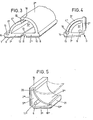
- Fig. 5 eine stirnseitige perspektivische Ansicht einer vierten Ausführungsform.
- 1 is an end perspective view of a first embodiment,
- 2 shows a cross section through a second embodiment,
- 3 shows an end perspective view of a third embodiment in the unattached state,
- Fig. 4 is an end view of the embodiment of FIG. 3 in the installed state and
- Fig. 5 is an end perspective view of a fourth embodiment.
Die in Fig. 1 dargestellte Ausführungsform einer Kabelschutzeinrichtung weist zwei Schenkel 1 und 2 auf, welche einen rechten Winkel einschließen. An den Enden der Schenkel 1 bzw. 2 sind im Querschnitt etwa kreisringabschnittsförmige Abdeckungen 3 und 4 vorgesehen, wobei die (innere) Abdeckung 4 am Ende des Schenkels 1 etwas nach innen versetzt angeordnet ist, so daß die (äußere) Abdeckung 3 mit der freien Längskante des Schenkels 1 harmonisch abschließend darübergreifen kann. Zwischen den Schenkel 1, 2 und den Abdeckungen 3, 4 wird ein Hohlraum 5 eingeschlossen, in welchem schematisch angedeutet ein Kabel 6 verlegt ist. Durch das verwendete gummiartige also weichelastische Material weisen die Abdeckungen 3 bzw. 4 eine solche Eigenelastizität auf, daß sie sich elastisch zurückklappen lassen, um ein Kabel entweder zu verlegen oder herauszunehmen.The embodiment of a cable protection device shown in Fig. 1 has two
Die Befestigung der Kabelschutzeinrichtung erfolgt über Selbstklebeschichten 7 und 8, welche jeweils durch eine Abziehfolie 9, lo abgedeckt sind, die sich zum Verlegen mühelos entfernen läßt. Es braucht dann lediglich nur noch der eine Schenkel 1 gegen den Fuß einer Wand und der andere Schenkel 2 gegen den Boden gedrückt zu werden.The cable protection device is attached via self-
Die in Fig. 2 dargestellte Ausführungsform unterscheidet sich von der in Fig. 1 dargestellten nur dadurch, daß die innere Abdeckung 4' erheblich verkürzt ausgebildet ist und somit praktisch nur noch einen Dichtungsanschlag für die eigentliche Abdeckung 3 darstellt. , In Fig. 2 ist eine Art der Verlegung veranschaulicht, wie sie sich insbesondere für die freie Verlegung auf Fußböden eignet, da durch das Aneinanderfügen zweier erfindungsgemäßer Kabelschutzeinrichtungen eine insgesamt abgerundete Oberseite geschaffen wird, welche keine Stolperkanten oder Angriffspunkte für Beschädigungen bietet. Die selbstklebenden Beschichtungen 7 der vertikalen Schenkel 1 dienen dabei zur Verbindung der beiden Kabelschutzeinrichtungen untereinander, während die selbstklebenden Beschichtungen 8 der horizontalen Schenkel 2 die Befestigung am Boden bewerkstelligen.The embodiment shown in Fig. 2 differs from that shown in Fig. 1 only in that the inner cover 4 'is significantly shortened and thus practically represents only a sealing stop for the
Besonders einfach kann die Verlegung von Kabeln 6 in der Kabelschutzeinrichtung dadurch erfolgen, daß das zu verlegende Kabel 6 mit einer Art Häkelnadel oder dergleichen erfaßt und unter elastischem Zurückklappen der Abdekkung 3 und gegebenenfalls 4 an einer Stelle in die Kabelschutzeinrichtung eingebracht wird. Es braucht dann lediglich das entsprechende Hilfsinstrument mit der Spitze im Inneren verbleibend an der Kabelschutzeinrichtung entlanggeführt werden, wobei das Kabel 6 dann mühelos in diese hineingleitet.The laying of
Wie aus Fig. 3 ersichtlich ist, kann eine Kabelschutzeinrichtung auch in der Weise hergestellt werden, daß die beiden Schenkel l" und 2" in einer gemeinsamen Ebene liegen und mittels eines elastischen Gelenks 11 miteinander verbunden sind, das ein Umklappen der beiden Schenkel 1", 2" in eine zueinander senkrechte Lage gestattet, wie sie in Fig. 4 dargestellt ist. Ein solches elastisches Gelenk wird dadurch hergestellt, daß die Dicke der Schenkel 1", 2" in diesem Bereich reduziert ist, wozu eine äußere Längsnut 12 und eine innere, dem Hohlraum 5" zugewandte Einkerbung 13 dienen. Zwischen der freien Längskante 14 des Schenkels 1" und der inneren Abdeckung 4" ist im Schenkel 1" eine sich durchgehend in Längsrichtung erstreckende Einrast-Ausnehmung 15 ausgebildet, die etwa halbkreisförmigen Querschnitt aufweist. Sie ist in ihrer Formgebung der einen Einrast- Bereich 16 bildenden Längskante der äußeren Abdeckung 3" angepaßt. Unmittelbar oberhalb der Einrast-Ausnehmung 15 ist am Übergang zwischen dem Schenkel 1" in die innere Abdeckung 4" eine Nut 17 angeordnet, die im Querschnitt einem sich ebenfalls in Längsrichtung erstreckenden widerhakenförmigen Vorsprung 18 angepaßt ist, der im Anschluß an den Einrast-Bereich an der Innenseite der äußeren Abdeckung 3" ausgebildet ist. Dieser Vorsprung 18 ist so angeordnet, daß nach seinem Eindrücken in die Nut 17 der Einrast-Bereich 16 der äußeren Abdeckung 3" in die Einrast-Ausnehmung 15 gepreßt wird, beide Teile sich in diesem Bereich also elastisch verformen und damit verspannen.As can be seen from FIG. 3, a cable protection device can also be produced in such a way that the two
Wie anschaulich aus einem Vergleich der Fig. 3 und 4 hervorgeht,ist die äußere Abdeckung 3" in unverspanntem Zustand flacher gewölbt als in verspanntem Zustand. Die Länge ihrer Sehne zwischen der Verbindungsstelle mit dem Schenkel 2" und ihrem Einrast-Bereich 16 ist also in unverspanntem Zustand größer als in verspanntem Zustand.3 and 4, the
Auch bei dieser Ausführungsform sind die Schenkel 1" und 2" mit jeweils einer selbstklebenden Beschichtung 7 bzw.8 versehen, auf denen eine Abziehfolie 9 bzw. lo-angebracht ist. Das Anbringen einer solchen selbstklebenden Beschichtung ist hierbei besonders einfach möglich, da sie bei der in Fig. 3 dargestellten Lage der Schenkel 1" und 2" zueinander erfolgen kann. Es kann in diesem Fall eine breite selbstklebende Beschichtung mit Abziehfolie aufgebracht und dann im Bereich der äußeren Längsnut 12 ein entsprechender Streifen herausgeschnitten werden.In this embodiment too, the
Auch die Ausführung nach den Fig.3 und 4 ist einstückig ausgebildet. Auch bei dieser Ausführungsform sind die Abdeckungen 3" und 4" konvex, also nach außen gewölbt.The embodiment according to FIGS. 3 and 4 is also made in one piece. Also in this embodiment, the
Bei der Ausführungsform nach Fig. 5 sind ebenfalls zwei mittels eines elastischen Gelenkes 11"' verbunde Schenkel 2"' und 1"' vorgesehen. Eine Abdeckung 3"' ist über einen vom Schenkel 2"' hochstehenden Steg 19 mit ersterem verbunden. Zwischen dem Steg 19 und der Abdeckung 3"' ist noch ein elastisches Gelenk 2o ausgebildet.5, two
Die Abdeckung 3 "' ist konkav ausgebildet, also - bei zueinander senkrechter Lage der Schenkel 1"', 2"' zu diesen hin durchgebogen.The
Vom freien Rand des anderen Schenkels 1"' steht ebenfalls ein Steg 21 hoch, an dessen dem Hohlraum 5 "' zugewandter Seite eine Einrast-Ausnehmung 15"' ausgebildet ist, die sich ebenfalls in Längsrichtung der Kabelschutzeinrichtung erstreckt. Diese Einrast-Ausnehmung ist dem entsprechenden Einrast-Bereich 16"' der Abdeckung 3"' im Querschnitt angepaßt. Auch hier wird wieder die Abdeckung 3 "' beim Einrasten in die Einrast-Ausnehmung 15''' elastisch zum Hohlraum 5 "' hin verspannt. Die strichpunktierte Darstellung der Abdeckung 3"' zeigt diese in einer zurückgeklappten Lage, in der ein Einlegen bzw. Entnehmen eines Kabels 6 möglich ist. Diese Stellung zum Schenkel 2"' entspricht etwa der Lage, in der die Kabelschutzeinrichtung gespritzt bzw. extrudiert wird, wobei dann allerdings der andere Schenkel 1"' sich in einer zum Schenkel 2"' fluchtenden Lage befindet.From the free edge of the
Bei den Ausführungsformen nach den Fig. 3 bis 5 kann die Verlegung von Kabeln 6 ähnlich erfolgen, wie bei der Ausführungsform nach den Fig. 1 und 2. Das Einrasten der Abdeckung 3" bzw. 3 "' in die Einrast-Ausnehmung 15 bzw. 15 "' kann von Hand erfolgen. Zum Lösen dieser Rastverbindung wird ein Schraubendreher und ein vergleichbares flaches Werkzeug verwendet, mittels dessen von außen her in die Einrast-Ausnehmung eingegriffen wird.In the embodiments according to FIGS. 3 to 5,
Die Kabelschutzeinrichtung eignet sich ebenso für die Verlegung von Fernsehantennenkabeln, Lautsprecherkabeln, Leitungen für Klingeln und Haustelefone, Gegensprechanlagen und dgl. im Wohnraum wie für Telefonzuleitungen, Leitungen für,Sprechanlagen, Datenübertragungsleitungen und dgl. im Büro.The cable protection device is also suitable for laying television antenna cables, loudspeaker cables, lines for bells and in-house telephones, intercom systems and the like in the living room, as well as for telephone lines, lines for, intercom systems, data transmission lines and the like in the office.
Um eine Anpassung an unterschiedliche Raumgestaltungen zu erreichen, kann die äußere Abdeckung 3, 3", 3"' eine Dekor-Oberfläche aufweisen, wobei sogar auch eine Relief-Gestaltung möglich ist. So kann z.B. vorgesehen sein, daß die Oberfläche holzartig gestaltet ist, wobei der entsprechende Relief-Charakter durch eine korrespondierende Farbgebung ergänzt wird.In order to adapt to different room designs, the
Claims (10)
Priority Applications (1)
| Application Number | Priority Date | Filing Date | Title |
|---|---|---|---|
| US06/565,213 US4530865A (en) | 1982-12-30 | 1983-12-23 | Cable protection device |
Applications Claiming Priority (2)
| Application Number | Priority Date | Filing Date | Title |
|---|---|---|---|
| DE8236831U DE8236831U1 (en) | 1982-12-30 | 1982-12-30 | Cable protection device |
| DE8236831U | 1982-12-30 |
Publications (2)
| Publication Number | Publication Date |
|---|---|
| EP0114918A2 true EP0114918A2 (en) | 1984-08-08 |
| EP0114918A3 EP0114918A3 (en) | 1985-08-28 |
Family
ID=6746999
Family Applications (1)
| Application Number | Title | Priority Date | Filing Date |
|---|---|---|---|
| EP83104253A Ceased EP0114918A3 (en) | 1982-12-30 | 1983-04-30 | Dispositif de protection de câble |
Country Status (2)
| Country | Link |
|---|---|
| EP (1) | EP0114918A3 (en) |
| DE (1) | DE8236831U1 (en) |
Cited By (7)
| Publication number | Priority date | Publication date | Assignee | Title |
|---|---|---|---|---|
| FR2643516A1 (en) * | 1989-02-17 | 1990-08-24 | Sprenger Walter | PROTECTIVE SHEATHING DEVICE FOR CABLES |
| EP0739069A1 (en) * | 1995-04-22 | 1996-10-23 | Zumtobel Licht GmbH | Combined connection device |
| FR2738272A1 (en) * | 1995-08-29 | 1997-03-07 | Guyonnet Armand | CORNER OVERLAP PROFILE, FORMING PLINTH AND EXPANSION JOINT AND ENDING PART OF PROFILES IN ACCORDANCE WITH THE INVENTION |
| DE19603262A1 (en) * | 1996-01-30 | 1997-07-31 | Leopold Dipl Ing Marek | Decorative covering adhesive tape e.g. for laying cables in offices and living rooms |
| DE19751611A1 (en) * | 1996-06-05 | 1999-05-27 | Georg Krain | Installation channel with sheet covering used for e.g. indirect interior lighting system |
| GB2426874A (en) * | 2005-06-03 | 2006-12-06 | Stewart Alexander Collis Smith | Cable screener |
| CN115085136A (en) * | 2022-08-22 | 2022-09-20 | 山东博诚电气有限公司 | External protection structure for underground cable |
Citations (6)
| Publication number | Priority date | Publication date | Assignee | Title |
|---|---|---|---|---|
| GB1030371A (en) * | 1964-02-11 | 1966-05-25 | William Adrian Larry Collier | Protective ducting for electric wiring |
| US3786171A (en) * | 1973-01-22 | 1974-01-15 | Kvoda Plastics Ltd | Integral hinged wiring raceway |
| GB1420216A (en) * | 1972-03-17 | 1976-01-07 | Carter W T H | Cable covering device |
| FR2415380A1 (en) * | 1978-01-18 | 1979-08-17 | Texunion | Adhesive sheath for linear elements such as wires - comprises e.g. PVC hinged profile with adhesive-coated slit base |
| FR2448240A1 (en) * | 1979-01-31 | 1980-08-29 | Inovac Sa | Runway for cables comprising E-shaped duct - with long flexible outer arms which fold inwards to form two closed parallel channels |
| WO1980002476A1 (en) * | 1979-05-03 | 1980-11-13 | Ericsson Telefon Ab L M | Band-shaped device for forming a pipe-shaped protection cover |
-
1982
- 1982-12-30 DE DE8236831U patent/DE8236831U1/en not_active Expired
-
1983
- 1983-04-30 EP EP83104253A patent/EP0114918A3/en not_active Ceased
Patent Citations (6)
| Publication number | Priority date | Publication date | Assignee | Title |
|---|---|---|---|---|
| GB1030371A (en) * | 1964-02-11 | 1966-05-25 | William Adrian Larry Collier | Protective ducting for electric wiring |
| GB1420216A (en) * | 1972-03-17 | 1976-01-07 | Carter W T H | Cable covering device |
| US3786171A (en) * | 1973-01-22 | 1974-01-15 | Kvoda Plastics Ltd | Integral hinged wiring raceway |
| FR2415380A1 (en) * | 1978-01-18 | 1979-08-17 | Texunion | Adhesive sheath for linear elements such as wires - comprises e.g. PVC hinged profile with adhesive-coated slit base |
| FR2448240A1 (en) * | 1979-01-31 | 1980-08-29 | Inovac Sa | Runway for cables comprising E-shaped duct - with long flexible outer arms which fold inwards to form two closed parallel channels |
| WO1980002476A1 (en) * | 1979-05-03 | 1980-11-13 | Ericsson Telefon Ab L M | Band-shaped device for forming a pipe-shaped protection cover |
Cited By (10)
| Publication number | Priority date | Publication date | Assignee | Title |
|---|---|---|---|---|
| FR2643516A1 (en) * | 1989-02-17 | 1990-08-24 | Sprenger Walter | PROTECTIVE SHEATHING DEVICE FOR CABLES |
| GB2229867A (en) * | 1989-02-17 | 1990-10-03 | Walter Sprenger | Cable protection device |
| EP0739069A1 (en) * | 1995-04-22 | 1996-10-23 | Zumtobel Licht GmbH | Combined connection device |
| FR2738272A1 (en) * | 1995-08-29 | 1997-03-07 | Guyonnet Armand | CORNER OVERLAP PROFILE, FORMING PLINTH AND EXPANSION JOINT AND ENDING PART OF PROFILES IN ACCORDANCE WITH THE INVENTION |
| EP0761906A1 (en) * | 1995-08-29 | 1997-03-12 | Armand Guyonnet | Angle covering profile forming a plinth and expansion joint and abutment piece for profiles according to the invention |
| DE19603262A1 (en) * | 1996-01-30 | 1997-07-31 | Leopold Dipl Ing Marek | Decorative covering adhesive tape e.g. for laying cables in offices and living rooms |
| DE19751611A1 (en) * | 1996-06-05 | 1999-05-27 | Georg Krain | Installation channel with sheet covering used for e.g. indirect interior lighting system |
| GB2426874A (en) * | 2005-06-03 | 2006-12-06 | Stewart Alexander Collis Smith | Cable screener |
| CN115085136A (en) * | 2022-08-22 | 2022-09-20 | 山东博诚电气有限公司 | External protection structure for underground cable |
| CN115085136B (en) * | 2022-08-22 | 2022-11-15 | 山东博诚电气有限公司 | External protection structure for underground cable |
Also Published As
| Publication number | Publication date |
|---|---|
| EP0114918A3 (en) | 1985-08-28 |
| DE8236831U1 (en) | 1983-09-29 |
Similar Documents
| Publication | Publication Date | Title |
|---|---|---|
| DE2621772A1 (en) | CORNER BAR | |
| EP0114918A2 (en) | Dispositif de protection de câble | |
| DE2610939C2 (en) | Work table, especially a desk | |
| DE102014102465B4 (en) | switch cabinet | |
| EP3835539B1 (en) | Kit for a frame | |
| DE4017330C1 (en) | ||
| DE2701128C2 (en) | Tension profile rail for attaching wall coverings | |
| EP0151272A2 (en) | Angular apparatus for threading conductors | |
| DE4242589A1 (en) | Frame for switch cubicle door panel - has frame of irregular section with edge supporting panel and cover strip to hold panel in place | |
| DE2604126A1 (en) | Rubber-like seal for housing of two or more parts - comprises string of soft foam which is foamed freely in groove in one part | |
| DE3509989C2 (en) | ||
| EP1102375B1 (en) | Cable ducting channel | |
| DE102021134511A1 (en) | Kit for a frame and profile connector | |
| DE8300909U1 (en) | Cut to form a double-walled container with a folding wall | |
| DE3906421C2 (en) | Lockable plug connection | |
| DE1509777A1 (en) | Molded part made of plastic for covering walls | |
| DE202009013621U1 (en) | Inner corner for cable channels | |
| EP2602421A2 (en) | Box for roller blinds and the like | |
| DE3904867A1 (en) | CABLE PROTECTION DEVICE | |
| DE1596229C3 (en) | Bracket for carrying handles on battery boxes | |
| AT402988B (en) | CABLE GUIDE DEVICE | |
| DE7025049U (en) | CONNECTORS FOR FASTENING A FRAME TO A WALL TONGS. | |
| DE3825300C2 (en) | ||
| DE2540840A1 (en) | Conductor carrier for light current wiring - having channels for cables and adhesive layer for fixing | |
| DE3136404A1 (en) | Arch-type greenhouse with translucent walls |
Legal Events
| Date | Code | Title | Description |
|---|---|---|---|
| PUAI | Public reference made under article 153(3) epc to a published international application that has entered the european phase |
Free format text: ORIGINAL CODE: 0009012 |
|
| AK | Designated contracting states |
Designated state(s): AT BE CH DE FR GB IT LI NL SE |
|
| PUAL | Search report despatched |
Free format text: ORIGINAL CODE: 0009013 |
|
| AK | Designated contracting states |
Designated state(s): AT BE CH DE FR GB IT LI NL SE |
|
| 17P | Request for examination filed |
Effective date: 19860125 |
|
| 17Q | First examination report despatched |
Effective date: 19870202 |
|
| R17C | First examination report despatched (corrected) |
Effective date: 19870624 |
|
| STAA | Information on the status of an ep patent application or granted ep patent |
Free format text: STATUS: THE APPLICATION HAS BEEN REFUSED |
|
| 18R | Application refused |
Effective date: 19880716 |