EP0115148A2 - Détecteur d'oxygène - Google Patents
Détecteur d'oxygène Download PDFInfo
- Publication number
- EP0115148A2 EP0115148A2 EP83307682A EP83307682A EP0115148A2 EP 0115148 A2 EP0115148 A2 EP 0115148A2 EP 83307682 A EP83307682 A EP 83307682A EP 83307682 A EP83307682 A EP 83307682A EP 0115148 A2 EP0115148 A2 EP 0115148A2
- Authority
- EP
- European Patent Office
- Prior art keywords
- ceramics
- group
- zirconia
- components
- phase
- Prior art date
- Legal status (The legal status is an assumption and is not a legal conclusion. Google has not performed a legal analysis and makes no representation as to the accuracy of the status listed.)
- Granted
Links
Images


Classifications
-
- G—PHYSICS
- G01—MEASURING; TESTING
- G01N—INVESTIGATING OR ANALYSING MATERIALS BY DETERMINING THEIR CHEMICAL OR PHYSICAL PROPERTIES
- G01N27/00—Investigating or analysing materials by the use of electric, electrochemical, or magnetic means
- G01N27/26—Investigating or analysing materials by the use of electric, electrochemical, or magnetic means by investigating electrochemical variables; by using electrolysis or electrophoresis
- G01N27/403—Cells and electrode assemblies
- G01N27/406—Cells and probes with solid electrolytes
- G01N27/407—Cells and probes with solid electrolytes for investigating or analysing gases
- G01N27/4073—Composition or fabrication of the solid electrolyte
-
- C—CHEMISTRY; METALLURGY
- C04—CEMENTS; CONCRETE; ARTIFICIAL STONE; CERAMICS; REFRACTORIES
- C04B—LIME, MAGNESIA; SLAG; CEMENTS; COMPOSITIONS THEREOF, e.g. MORTARS, CONCRETE OR LIKE BUILDING MATERIALS; ARTIFICIAL STONE; CERAMICS; REFRACTORIES; TREATMENT OF NATURAL STONE
- C04B35/00—Shaped ceramic products characterised by their composition; Ceramics compositions; Processing powders of inorganic compounds preparatory to the manufacturing of ceramic products
- C04B35/01—Shaped ceramic products characterised by their composition; Ceramics compositions; Processing powders of inorganic compounds preparatory to the manufacturing of ceramic products based on oxide ceramics
- C04B35/48—Shaped ceramic products characterised by their composition; Ceramics compositions; Processing powders of inorganic compounds preparatory to the manufacturing of ceramic products based on oxide ceramics based on zirconium or hafnium oxides, zirconates, zircon or hafnates
- C04B35/486—Fine ceramics
-
- C—CHEMISTRY; METALLURGY
- C04—CEMENTS; CONCRETE; ARTIFICIAL STONE; CERAMICS; REFRACTORIES
- C04B—LIME, MAGNESIA; SLAG; CEMENTS; COMPOSITIONS THEREOF, e.g. MORTARS, CONCRETE OR LIKE BUILDING MATERIALS; ARTIFICIAL STONE; CERAMICS; REFRACTORIES; TREATMENT OF NATURAL STONE
- C04B41/00—After-treatment of mortars, concrete, artificial stone or ceramics; Treatment of natural stone
- C04B41/80—After-treatment of mortars, concrete, artificial stone or ceramics; Treatment of natural stone of only ceramics
- C04B41/81—Coating or impregnation
- C04B41/85—Coating or impregnation with inorganic materials
- C04B41/88—Metals
-
- C—CHEMISTRY; METALLURGY
- C04—CEMENTS; CONCRETE; ARTIFICIAL STONE; CERAMICS; REFRACTORIES
- C04B—LIME, MAGNESIA; SLAG; CEMENTS; COMPOSITIONS THEREOF, e.g. MORTARS, CONCRETE OR LIKE BUILDING MATERIALS; ARTIFICIAL STONE; CERAMICS; REFRACTORIES; TREATMENT OF NATURAL STONE
- C04B41/00—After-treatment of mortars, concrete, artificial stone or ceramics; Treatment of natural stone
- C04B41/80—After-treatment of mortars, concrete, artificial stone or ceramics; Treatment of natural stone of only ceramics
- C04B41/81—Coating or impregnation
- C04B41/89—Coating or impregnation for obtaining at least two superposed coatings having different compositions
-
- H—ELECTRICITY
- H01—ELECTRIC ELEMENTS
- H01M—PROCESSES OR MEANS, e.g. BATTERIES, FOR THE DIRECT CONVERSION OF CHEMICAL ENERGY INTO ELECTRICAL ENERGY
- H01M8/00—Fuel cells; Manufacture thereof
- H01M8/10—Fuel cells with solid electrolytes
- H01M8/12—Fuel cells with solid electrolytes operating at high temperature, e.g. with stabilised ZrO2 electrolyte
- H01M8/124—Fuel cells with solid electrolytes operating at high temperature, e.g. with stabilised ZrO2 electrolyte characterised by the process of manufacturing or by the material of the electrolyte
- H01M8/1246—Fuel cells with solid electrolytes operating at high temperature, e.g. with stabilised ZrO2 electrolyte characterised by the process of manufacturing or by the material of the electrolyte the electrolyte consisting of oxides
- H01M8/1253—Fuel cells with solid electrolytes operating at high temperature, e.g. with stabilised ZrO2 electrolyte characterised by the process of manufacturing or by the material of the electrolyte the electrolyte consisting of oxides the electrolyte containing zirconium oxide
-
- Y—GENERAL TAGGING OF NEW TECHNOLOGICAL DEVELOPMENTS; GENERAL TAGGING OF CROSS-SECTIONAL TECHNOLOGIES SPANNING OVER SEVERAL SECTIONS OF THE IPC; TECHNICAL SUBJECTS COVERED BY FORMER USPC CROSS-REFERENCE ART COLLECTIONS [XRACs] AND DIGESTS
- Y02—TECHNOLOGIES OR APPLICATIONS FOR MITIGATION OR ADAPTATION AGAINST CLIMATE CHANGE
- Y02E—REDUCTION OF GREENHOUSE GAS [GHG] EMISSIONS, RELATED TO ENERGY GENERATION, TRANSMISSION OR DISTRIBUTION
- Y02E60/00—Enabling technologies; Technologies with a potential or indirect contribution to GHG emissions mitigation
- Y02E60/30—Hydrogen technology
- Y02E60/50—Fuel cells
-
- Y—GENERAL TAGGING OF NEW TECHNOLOGICAL DEVELOPMENTS; GENERAL TAGGING OF CROSS-SECTIONAL TECHNOLOGIES SPANNING OVER SEVERAL SECTIONS OF THE IPC; TECHNICAL SUBJECTS COVERED BY FORMER USPC CROSS-REFERENCE ART COLLECTIONS [XRACs] AND DIGESTS
- Y02—TECHNOLOGIES OR APPLICATIONS FOR MITIGATION OR ADAPTATION AGAINST CLIMATE CHANGE
- Y02P—CLIMATE CHANGE MITIGATION TECHNOLOGIES IN THE PRODUCTION OR PROCESSING OF GOODS
- Y02P70/00—Climate change mitigation technologies in the production process for final industrial or consumer products
- Y02P70/50—Manufacturing or production processes characterised by the final manufactured product
Definitions
- the present invention relates to zirconia and/or hafnia-containing ceramics, particularly ceramics having a high electric resistance and ceramics having a high mechanical strength.
- Embodiments of such zirconia ceramics are disclosed in U.S. Patent 4,266,979, U.S. Patent 4,360,598 and Japanese Patent Laid-Open Application No. 58-55,373.
- zirconia ceramics can be used as a solid electrolyte because oxygen ion vacancy caused by addition of a stabilizer such as Y 2 0 3 , CaO and the like to Zr0 2 as well known. That is, when the position Zr of positive tetravalent ion is substituted with Y 3+ or Ca2+ of positive trivalent or divalent ion, the positive ion valence number per crystal lattice is reduced, so that the number of oxygen ion 02 having negative ion is reduced for maintaining the electric neutrality and the movement of oxygen ion becomes feasible due to oxygen ion vacancy caused therefrom.
- a stabilizer such as Y 2 0 3 , CaO and the like
- the concentration cell constructed with such a theory is reversible and if there is difference of the oxygen concentration between both ends of the solid electrolyte, the electromotive force is caused by the well known Nernst's equation and reversely, when a direct current voltage is applied to both ends of the solid electrolyte to flow current,-- oxygen ion moves from negative direction toward positive direction and oxygen can be moved from one side of the solid electrolyte to another side. This is well known as oxygen pump.
- the prior zirconia ceramics has been very weak against the application of the direct current voltage.
- the portion constructing the concentration cell is heated with a heater.
- This structure is shown, for example, in U.S. Patent 4,334,974.
- the heater is heated at a direct current voltage of about 12-14 V which is battery voltage and therefore an insulating layer must be interposed between the heater and the concentration cell in order that the voltage for heating the heater does not influence upon the electromotive force of the concentration cell.
- the zirconia ceramics is not only broken by the direct current voltage of 12-14 V applied to the heater, but also the voltage applied to the heater influences upon the electromotive force of the concentration cell due to zirconia of which the electric resistance becomes lower at a high temperature.
- alumina ceramics which is a high resistor as an insulating layer, is used, the insulating property is good but said ceramics is different from zirconia ceramics constructing the concentration cell in the thermal expansion coefficient, so that in the use when the heat cycle between a high temperature and a low temperature is vigorous, alumina ceramics is exfoliated from the concentration cell composed of zirconia ceramics.
- such an oxygen sensor has a drawback that in the production, when zirconia and alumina which are different in the firing shrinkage percent, are co-fired, zirconia and alumina are exfoliated upon firing and cooling.
- the present invention has been made for solving the above described drawbacks and aims to obtain ceramics having the substantially same firing shrinkage and thermal expansion properties with conventional zirconia ceramics, a high electric resistivity, that is a satisfactory direct current voltage resistance and a high mechanical strength.
- the present invention lies in ceramics consisting essentially of 5-30 mol% of at least one component selected from Group A consisting of YO 1.5 , ScO 1.5 , SmO 1.5 , EuO 1.5 , GdO 1.5 , TbO 1.5 , DyO 1.5 , HoO 1.5 , ErO 1.5 , TmO 1.5 , YbO 1.5 , LuO 1.5 , CaO and MgO, 5-40 mol% of at least one component selected from Group B consisting of NbO 2.5 and TaO 2.5 and 30-90 mol% of at least one component selected from Group C consisting of Zr0 2 and Hf0 2 , the composition preferably satisfying the following equation
- the prior zirconia ceramics only components belonging to Group A defined in-the present invention, such as yttria, calcia, magnesia and the like are added as the stabilizer.
- a sintering aid somewhat is added thereto but the sintering aid has substantially no relation to the stabilization of zirconia ceramics. Therefore, the prior zirconia ceramics have a large number of oxygen ion vacancies in the crystal lattice as mentioned above.
- the present invention is characterized in that the amount of oxygen ion vacancy is reduced by adding the components belonging to Group B, that is components which become pentavalent positive ions, other than the stabilizer belonging to Group A.
- the components belonging to Group B that is components which become pentavalent positive ions
- both YO 1.5 and NbO 2.5 form a solid solution together with Zr0 2 in the crystal and Y3+ ion and Nb 5+ ion are formed other than Zr 4+ ion.
- Y 3+ ion and Nb 5+ ion are equimolar number, so that these ions become tetravalent positive ion in average and therefore become the same electric charge as Zr 4+ ion and O 2- ion in the crystal lattice can maintain the electric neutrality in the amount of the stoichiometric volume of Zr0 2 , so that 02 ion vacancy is not substantially caused. Accordingly, O 2- ion hardly moves in the crystal and the ceramics having the electrically high resistance are formed.
- Fig. 1 shows the average value of the electric resistivity of ceramics obtained by various combinations of the present invention.
- each of Groups A, B and C are selected by the following reason. Any components shown in Group A can be utilized even in one component as the stabilizer of Zr0 2 or Hf0 2 . This has been well known.
- the components shown in Group B are added in order to reduce the oxygen ion vacancy and increase the electric resistivity. Therefore, any components which become positive ions of five or more valence, are active but in order to form a solid solution together with Zr0 2 or Hf0 2 , the components must have a given ion radius and as the results of a large number of experiments, NbO 2.5 and TaO 2.5 are most effective.
- the selection of these two components is a characteristic of the present invention.
- the elements shown in Group C are selected so that the same thermal expansion property as the prior zirconia ceramics is obtained. It has been well known that Zr0 2 and Hf0 2 are similar in various properties and the same effects have been obtained in the experiments by which the present invention has been accomplished.
- composition- range of each group has been determined by the following reasons.
- each of Group A and Group B have no activity to the stabilization of Zr0 2 and/or Hf0 2 against the components of Group C in an addition amount of less than 5 mol%.
- ZrO 2 and/or Hf0 2 can be stabilized in the crystal phase containing tetragonal or cubic phase, in some cases monoclinic phase in the addition of more than 4 mol% but in only the components of Group B, these components have no activity for stabilizing Zr0 2 and/or Hf0 2 .
- both the components of Group A and Group B are added in an amount of at least 5 mol% respectively, Zr0 2 and/or Hf0 2 are stabilized and the ceramics having a high resistance can be obtained.
- stabilization of Zr0 2 and/or Hf0 2 used herein means that the formation of monoclinic phase is made few or the monoclinic phase is not formed as in so-called “partially stabilized zirconia” or “full stabilized zirconia”.
- crystal phase of the ceramics of the present invention there is either crystal phase of tetragonal, cubic or monoclinic phase, or a mixed phase thereof but the crystal phase shows different behavior from the case where only the stabilizer belonging to Group A is added to Zr0 2 as in the prior arts.
- the ceramics consists mainly of a tetragonal phase and in addition, a monoclinic phase and a compound phase presumed to be formed by reacting YO 1.5 with NbO 2.5 may be slightly precipitated.
- the crystal phase of the ceramics in the case of other compositions of the present invention when the amount of mole of components of Group B is smaller than that of the components of Group A, becomes cubic, tetragonal or the mixed phase thereof but when the amount of mole of the components of Group B is larger than that of the components of Group A, a tetragonal phase becomes the main part and in some cases, a monoclinic phase and a phase (referred to as "X phase" hereinafter) presumed to be a compound phase of the components of Group A and the components of Group B are precipitated.
- the crystal phase of the ceramics of the present invention varies according to the combination of various factors, for example, the crystal grain size of the starting material, mixing process of the components of each group, the firing condition and the like.
- the electric resistivity is similarly higher than the prior zirconia ceramics but when the amount of monoclinic phase becomes larger, if such ceramics is left to stand at a temperature range of about 250°C for a long time, the ceramics is apt to be deteriorated and when the amount of X phase becomes larger, the electric resistivity somewhat lowers and also the flexural strength of the ceramics lowers and these cases are not desirable.
- the crystal phase of the ceramics of the present invention preferably consists mainly of tetragonal phase.
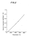
- the thermal expansion coefficient of the ceramics obtained in the present invention varies linearly both when the temperature is raised from room temperature to 800°C or is fallen, as one embodiment is shown in Fig. 2 and there is no hysteresis due to the phase transformation and the like.
- the thermal expansion coefficient thereof is 0.9 ⁇ 1.1X10 -5 °C -1 and is not substantially different from 1.0 ⁇ 1.1x10 -5 °C -1 of the prior stabilized zirconia ceramics.
- the sample in Fig. 2 is the composition of 20 mol% of YO 1.5 , 21 mol% of TaO 2.5 and 59 mol% of Zr0 2 but even in other compositions of the present invention, the behavior is not varied.
- the ceramics of the present invention can be produced as follows.
- the starting material containing these components may be powdery oxides or other compounds which are converted into oxides through the thermal decomposition.
- the powdery oxides when used as the starting material, when the average grain size of the powders is less than 1 ⁇ m, the mixing is easy and such starting material is preferable.
- the mixing is effected by a wet process, after mixing, the mixture is thoroughly dried. Then, if necessary, the mixture is calcined.
- This calcination when the starting material being not oxides is used, has the effect, by which the starting material is converted into oxides and when only the starting material of oxides is used, the calcination has the effect for promoting the mixing of the starting material.
- the calcining temperature may be an optional temperature of about 400-1,200°C.
- the mixture is pulverized, when the mixture is solidified by the calcination and the like, the mixture is preferably coarsely crushed by a mortar, roll crusher and the like.
- the pulverizing is carried out by a ball mill and the like.
- anyone of wet- pulverizing and dry-pulverizing may be used but the dry-pulverizing using a ball mill, a vibration mill and the like is preferable.
- the dry-pulverizing has the effects that the pulverizing time is short, the firing temperature is low, the firing shrinkage percent is reduced and the like, and the components of Group A, the components of Group B and the components of Group C are mixed thoroughly and the solid solution is readily formed. As the results, the cermics having a high electric resistivity can be easily obtained.
- the firing temperature is preferred to be a temperature range of 1,000-1,600 0 C.
- the firing atmosphere may be any of air, oxidizing atmosphere and reducing atmosphere. In the reducing atmosphere, oxygen in the sintered body is taken off and the product may become blackish but thereafter if the sintered body is annealed in air, the blackening can be simply eliminated.
- the firing may be effected by a hot press and the like.
- clay, alumina, glass, etc. may be contained in an amount of less than about 30% by weight as a sintering aid in addition to the components listed as the above described Group A, Group B and Group C.
- a sintering aid in addition to the components listed as the above described Group A, Group B and Group C.
- breakage may be caused upon firing but this can be solved by the addition of the sintering aid.
- These substances do not particularly noticeably affect on the electric resistivity.
- the addition is excessive, the firing shrinkage percent upon the production and the thermal expansion coefficient of the ceramics vary, so that the amount exceeding about 30% by weight is not preferable.
- Zn0 2 starting material contains about 1-2% by weight of Hf0 2
- Zr0 2 " referred to in the present invention contains this amount of Hf0 2 and when the description of "mixing of Zr0 2 and Hf0 2 " used herein means the mixture of Zr0 2 containing a slight amount of Hf0 2 with purified Hf0 2 .
- examination has been made with respect to Zr0 2 having a high purity in which the content of Hf0 2 is less than 100 ppm and of course, Zr0 2 starting material having a high purity may be used.
- the measurement of the electric resistivity was as follows. On both surfaces of a disc-shaped ceramics having a diameter of more than 20 mm and a thickness of about 1 mm, were formed electrodes and such a ceramics was put in an electric furnace of air atmosphere and the electric resistivity was measured by a direct current two terminal process. The measuring temperature was 600°C and the applied voltage was 0.1-50 V.
- the crystal phase was measured as follows. Polished mirror face of a disc-shaped ceramics having a diameter of about 15 mm and a thickness of about 3 mm were measured with an x-ray diffractometer.
- the flexural strength was measured as follows. A rod-shaped (3x4x40 mm) and chamfered ceramics was - used and the ceramics was measured by four point bending process of an external span of 30 mm, an internal span of 10 mm and a cross head speed of 0.5 mm/min.
- the thermal expansion coefficient was measured by using a rod-shaped (4x4x50 mm) ceramics and by means of a differential expansion meter in which quartz glass is a standard.
- a mixture consisting of zirconium oxide powder or hafnium oxide powder, powder of oxide consisting of the component of Group A or a compound for example, yttrium nitride, which is formed into the component of Group A through thermal decomposition, and powder consisting of the component of Group B in a mixing ratio shown in the following Table 1 was calcined at 800°C. After the calcination, the calcined product was mixed with a sintering aid in the case when a sintering aid shown in Table 1 was to be added, and then mixed with 0.5% by weight of polyethyleneglycol stearate as a pulverizing aid, and the resulting mixture was pulverized in dry state for 20-200 hours.
- the resulting powder was press molded and then fired at 1,250-1,400°C.
- the electric resistivity of the resulting sintered body was measured.
- Table 1 It can be seen from Table 1 that the electric resistivity of the ceramics of Sample Nos. 1-19, which contain the component of Group B according to the present invention, is higher by as high as about 10 2- 10 5 ⁇ cm than that of the ceramics of Sample No. 20, which does not contain the component of Group B.
- the thermal expansion coefficient, flexural strength, main crystal phase of each ceramics obtained in Example 1 and shown in Table 1 were measured. The obtained results are shown in the following Table 2. It can be seen from Table 2 that the thermal expansion coefficient of ceramics of Sample Nos. 1-19 according to the present invention ranges from 0.9x10 -5 °C -1 to 1.0x10 -5 °C -1 , and is different by only small value within 0.2x10 -5 °C -1 from that of 1.1x10 -5 °C -1 of conventional ceramics of Sample No. 20. While, the flexural strength of the ceramics of the present invention is higher than that of the conventional ceramics of Sample No.
- the ceramics of the present invention have a crystal phase consisting mainly of cubic phase.
- the ceramics of Sample Nos. 1-20 were left to stand at 250°C for 1,000 hours in the air to effect a durability test, and the electric resistivity, thermal expansion coefficient and flexural strength of the above treated ceramics were measured. As the results, it was found that all of these properties did not substantially change from the properties before the durability test as shown in Table 2. Further, a disk-shaped test piece was produced from each of these ceramics, and a durability test of the ceramics was effected by applying 15 V of DC current between both electrodes for 1,000 hours in an electric furnace kept at 800°C. As the result, it was found that the conventional ceramics of Sample No. 20 was broken, but the ceramics according to the present invention were not broken, and their electric resistivity did not substantially change from the electric resistivity before the application of the DC current.
- Sample Nos. 21-32 are ceramics of the present invention
- Sample Nos. 33-36 are ceramics outside the scope of the present invention.
- the resulting ceramics were measured with respect to the electric resistivity, thermal expansion coefficient, flexural strength and crystal phase. The obtained results are shown in Table 3. It can be seen from Table 3 that all the electric resistivities of the ceramics are high and are in the order of l0 7 ⁇ cm. While, the thermal expansion coefficients thereof are within the range of 0.9X10 -5 °C -1 ⁇ 1.0X10 -5 °C -1 and are substantially the same as those of conventional zirconia ceramics.
- the crystal phase of the ceramics of the present invention consists of tetragonal phase or a mixed phase of tetragonal phase and cubic phase.
- Oxygen sensors were produced by using conventional zirconia ceramics and ceramics of the present invention.
- Fig. 3 shows the development of the sensors.
- a measuring electrode 2 is arranged on one surface of a solid electrolyte 1 consisting of zirconia ceramics, and a reference electrode 3 is arranged on another surface thereof.
- the measuring electrode 2 is contacted through a porous spinel layer 4 with a gas to be measured, and the reference electrode 3 is contacted with the air through a cavity 7 formed by a rectangular layer 5 and an airtight layer 6, both consisting of zirconia ceramics having the same composition as that of the solid electrolyte 1, whereby an oxygen concentration cell 8 is formed.
- an insulating layer 9 is tightly adhered to the oxygen concentration cell 8
- a heater 10 is arranged on the surface of the insulating layer 9, a protecting layer 11 is laminated so as to cover the heater 10 to form an oxygen sensor element.
- This oxygen sensor element was produced in the following manner.
- Raw materials were mixed in a mixing ratio so as to form a mixture having the same composition as that of Sample No. 36 in Table 3, and the resulting mixture was treated according to the steps described in Example 1 to produce dried and pulverized zirconia powder.
- To 100 parts by weight of the dried and pulverized zirconia powder were added 8 parts by weight of polyvinylbutyral and 100 parts by weight of trichloroethylene, and the resulting mixture was homogeneously mixed for 16 hours in a ball mill to produce a zirconia slurry, and the zirconia slurry was spread into a plate- shaped article by a doctor blade method to produce a zirconia tape.
- a measuring electrode 2 was formed on another surface of the solid electrolyte 1, on which the reference electrode 3 was not arranged, by a spattering of platinum, and a porous spinel layer 4 was plasma-coated on the spattered platinum of measuring electrode 2.
- the resulting oxygen sensor wherein the ceramics of the present invention is used in the insulating layer 9 and protecting layer 11, is referred to as an oxygen sensor element A.
- an oxygen sensor element B wherein conventional zirconia ceramics having the same composition as that of the solid electrolyte 1 was used in the insulating layer 9 and protecting layer 11
- an oxygen sensor element C wherein alumina ceramics was used in the insulating layer 9 and protecting layer 11, were produced.
- the solid electrolyte 1 of each oxygen sensor element had a dimension of 0.5 mm thickness, 6 mm width and 40 mm length.
- the oxygen sensor element A using the ceramics of the present invention and the oxygen sensor element B using the conventional zirconia ceramics did not bend during the firing, and were good in the adhesion between the airtight layer 6 and the insulating layer 9.
- the oxygen sensor element C, wherein the alumina ceramics was used bent during the firing due to the difference of shrinkages during the firing between the zirconia ceramics, which formed the concentration cell 8, and the alumina ceramics, which formed the insulating layer 9 and protecting layer 11, and further somewhat cracked between the airtight layer 6 and the insulating layer 9.
- each oxygen sensor element was inserted into a propane gas burner while keeping such that air was introduced into the cavity 7, and the measuring electrode 2 was contacted with the burnt gas of propane, whereby an electromotive force caused between the measuring electrode 2 and the reference electrode 3 was measured in the following manner.
- the consumed amount of electric power in the heater 10 was about 4 W in all oxygen sensor elements, and the temperature of the vicinity of the measuring electrode 2 rose to about 580°C.
- the result of the measurement of the electromotive forces is shown in the following Table 4. It can be seen from Table 4 that, when the oxygen sensor elements were not heated without applying the DC current to the heater 10, ER was 850-855 mV and E L was 48-50 mV in all oxygen sensor elements.
- the ceramics of the present invention has substantially the same thermal expansion property as that of the zirconia ceramics, the ceramics of the present invention has an electric resistivity higher than that of the zirconia ceramics by as high as 10 1- 10 5 ⁇ cm, is not broken even in the application of DC current, and can be used as an insulator. Moreover, the ceramics of the present invention has high mechanical strength and. good durability over a wide temperature range.
- the ceramics of the present invention can be used as materials, which are required to have high mechanical strength and thermal stability, such as a structural material for internal combustion engine, cutting tool and the like, and further is very advantageous as a material which is laminated on zirconia ceramics used in a portion required to have electric insulating property like oxygen sensor. Therefore, the present invention is very contributable for the development of industry.
Priority Applications (1)
| Application Number | Priority Date | Filing Date | Title |
|---|---|---|---|
| EP89113292A EP0345824B1 (fr) | 1982-12-24 | 1983-12-16 | Procédé de production de céramiques |
Applications Claiming Priority (4)
| Application Number | Priority Date | Filing Date | Title |
|---|---|---|---|
| GB8236813 | 1982-12-24 | ||
| GB8236813 | 1982-12-24 | ||
| GB838311146A GB8311146D0 (en) | 1983-04-25 | 1983-04-25 | Zirconia ceramics |
| GB8311146 | 1983-04-25 |
Related Child Applications (1)
| Application Number | Title | Priority Date | Filing Date |
|---|---|---|---|
| EP89113292A Division-Into EP0345824B1 (fr) | 1982-12-24 | 1983-12-16 | Procédé de production de céramiques |
Publications (3)
| Publication Number | Publication Date |
|---|---|
| EP0115148A2 true EP0115148A2 (fr) | 1984-08-08 |
| EP0115148A3 EP0115148A3 (en) | 1985-05-29 |
| EP0115148B1 EP0115148B1 (fr) | 1990-04-11 |
Family
ID=26284789
Family Applications (1)
| Application Number | Title | Priority Date | Filing Date |
|---|---|---|---|
| EP83307682A Expired - Lifetime EP0115148B1 (fr) | 1982-12-24 | 1983-12-16 | Détecteur d'oxygène |
Country Status (4)
| Country | Link |
|---|---|
| US (1) | US4507394A (fr) |
| EP (1) | EP0115148B1 (fr) |
| CA (1) | CA1197675A (fr) |
| DE (2) | DE3381436D1 (fr) |
Cited By (10)
| Publication number | Priority date | Publication date | Assignee | Title |
|---|---|---|---|---|
| EP0134136A2 (fr) * | 1983-08-09 | 1985-03-13 | Ngk Insulators, Ltd. | Procédé de fabrication de corps en céramique |
| EP0177062A2 (fr) * | 1984-10-05 | 1986-04-09 | Max-Planck-Gesellschaft zur Förderung der Wissenschaften e.V. | Corps en oxydes à conductivité ionique et électronique |
| WO1989003033A1 (fr) * | 1987-10-01 | 1989-04-06 | Robert Bosch Gmbh | Capteur de temperature a coefficient position de temperature (ptc) et procede de fabrication d'elements de detection de temperature ptc pour ce capteur |
| EP0311264A2 (fr) * | 1987-10-09 | 1989-04-12 | Corning Glass Works | Eléments céramiques d'insertion pour outils coupants et leur production |
| EP0388747A2 (fr) * | 1989-03-24 | 1990-09-26 | Corning Incorporated | Matériaux céramiques possédant une pseudo-plasticité à température ambiante |
| EP0395912A1 (fr) * | 1989-05-02 | 1990-11-07 | Lonza Ag | Poudre d'oxyde de zirconium frittable et son procédé de préparation |
| DE4020385C2 (de) * | 1990-06-27 | 1999-11-18 | Bosch Gmbh Robert | Wärmetönungssensor |
| WO2009008979A1 (fr) * | 2007-07-05 | 2009-01-15 | Corning Incorporated | Isolation pour des systèmes sofc |
| DE202019002164U1 (de) | 2019-05-17 | 2019-06-21 | Heraeus Nexensos Gmbh | Verbesserter Hochtemperaturchip |
| EP3508463A1 (fr) * | 2018-01-03 | 2019-07-10 | Honeywell International Inc. | Revêtements de barrière thermique quinaires à faible conductivité pour composants de moteur à turbine |
Families Citing this family (30)
| Publication number | Priority date | Publication date | Assignee | Title |
|---|---|---|---|---|
| US5008221A (en) * | 1985-04-11 | 1991-04-16 | Corning Incorporated | High toughness ceramic alloys |
| EP0199459B1 (fr) * | 1985-04-11 | 1992-01-15 | Corning Glass Works | Alliages céramiques à ténacité élevée |
| EP0303622B1 (fr) * | 1986-04-29 | 1993-06-16 | Ceramatec, Inc. | Durcissement de corps ceramiques |
| US4886768A (en) * | 1987-11-13 | 1989-12-12 | Board Of Regents Acting For And On Behalf Of University Of Michigan | Toughened ceramics |
| US4891343A (en) * | 1988-08-10 | 1990-01-02 | W. R. Grace & Co.-Conn. | Stabilized zirconia |
| US5071799A (en) * | 1989-01-03 | 1991-12-10 | Edgar John P | Incandescent mantles |
| US5665262A (en) * | 1991-03-11 | 1997-09-09 | Philip Morris Incorporated | Tubular heater for use in an electrical smoking article |
| US5403748A (en) * | 1993-10-04 | 1995-04-04 | Dow Corning Corporation | Detection of reactive gases |
| DE4439883A1 (de) * | 1993-12-09 | 1995-06-14 | Bosch Gmbh Robert | Isolationsschichtsystem zur galvanischen Trennung von Stromkreisen |
| KR970001064B1 (ko) * | 1994-03-15 | 1997-01-25 | 한국과학기술연구원 | 고인성·내저온열화 정방정 지르코니아 복합체의 제조방법 |
| US6930066B2 (en) * | 2001-12-06 | 2005-08-16 | Siemens Westinghouse Power Corporation | Highly defective oxides as sinter resistant thermal barrier coating |
| US6946208B2 (en) | 1996-12-10 | 2005-09-20 | Siemens Westinghouse Power Corporation | Sinter resistant abradable thermal barrier coating |
| US6924040B2 (en) * | 1996-12-12 | 2005-08-02 | United Technologies Corporation | Thermal barrier coating systems and materials |
| KR100321293B1 (ko) * | 1999-05-07 | 2002-03-18 | 박호군 | 정방정 지르코니아 분말, 그를 이용한 정방정 지르코니아/알루미나 복합체 |
| US6173913B1 (en) * | 1999-08-25 | 2001-01-16 | Caterpillar Inc. | Ceramic check for a fuel injector |
| US7172947B2 (en) * | 2004-08-31 | 2007-02-06 | Micron Technology, Inc | High dielectric constant transition metal oxide materials |
| EP1757714A3 (fr) * | 2005-08-24 | 2008-07-23 | Brother Kogyo Kabushiki Kaisha | Méthode de production d'un film et d'une tête à jet d'encre |
| JP2007209913A (ja) * | 2006-02-10 | 2007-08-23 | Mazda Motor Corp | 触媒材およびその製造方法並びにディーゼルパティキュレートフィルタ |
| FR2897862B1 (fr) * | 2006-02-24 | 2008-05-09 | Saint Gobain Ct Recherches | Produit refractaire fondu et coule a forte teneur en zircone, presentant une resistivite electrique amelioree. |
| FR2910467B1 (fr) * | 2006-12-21 | 2010-02-05 | Saint Gobain Ct Recherches | Produit fritte dope a base de zircon et de zircone |
| US8367227B2 (en) * | 2007-08-02 | 2013-02-05 | Applied Materials, Inc. | Plasma-resistant ceramics with controlled electrical resistivity |
| FR2920153B1 (fr) * | 2007-08-24 | 2010-11-26 | Saint Gobain Ct Recherches | Produit refractaire a forte teneur en zircone dope. |
| FR2920152B1 (fr) * | 2007-08-24 | 2009-12-04 | Saint Gobain Ct Recherches | Refractaire a fortre teneur en zircone et teneur en silice elevee. |
| CN101265561B (zh) * | 2008-03-31 | 2010-06-02 | 北京航空航天大学 | 一种耐瞬态超高温的热障涂层陶瓷层的制备方法 |
| CN101995425A (zh) * | 2010-10-30 | 2011-03-30 | 无锡隆盛科技有限公司 | 一种汽车用氮氧化物传感器芯片 |
| FR2969145B1 (fr) | 2010-12-16 | 2013-01-11 | Saint Gobain Ct Recherches | Produit refractaire a haute teneur en zircone. |
| DE102012110210B4 (de) | 2012-10-25 | 2017-06-01 | Heraeus Sensor Technology Gmbh | Hochtemperaturchip mit hoher Stabilität |
| US11479846B2 (en) | 2014-01-07 | 2022-10-25 | Honeywell International Inc. | Thermal barrier coatings for turbine engine components |
| US11339671B2 (en) * | 2019-12-20 | 2022-05-24 | Honeywell International Inc. | Methods for manufacturing porous barrier coatings using air plasma spray techniques |
| CN113354398B (zh) * | 2021-07-08 | 2022-08-05 | 西安石油大学 | 一种三氧化二铝基高熵共晶陶瓷及其制备方法 |
Citations (2)
| Publication number | Priority date | Publication date | Assignee | Title |
|---|---|---|---|---|
| GB1048069A (en) * | 1964-10-20 | 1966-11-09 | Du Pont | Zirconia-containing compositions |
| EP0036786A1 (fr) * | 1980-03-26 | 1981-09-30 | Ngk Insulators, Ltd. | Céramiques en zircone et procédé pour leur préparation |
Family Cites Families (3)
| Publication number | Priority date | Publication date | Assignee | Title |
|---|---|---|---|---|
| US4173518A (en) * | 1974-10-23 | 1979-11-06 | Sumitomo Aluminum Smelting Company, Limited | Electrodes for aluminum reduction cells |
| JPS5546130A (en) * | 1978-09-29 | 1980-03-31 | Hitachi Ltd | Oxygen sensor |
| JPS5855373A (ja) * | 1981-09-24 | 1983-04-01 | 日本碍子株式会社 | ジルコニア磁器およびその製造法 |
-
1983
- 1983-12-08 US US06/559,269 patent/US4507394A/en not_active Expired - Lifetime
- 1983-12-09 CA CA000442972A patent/CA1197675A/fr not_active Expired
- 1983-12-16 EP EP83307682A patent/EP0115148B1/fr not_active Expired - Lifetime
- 1983-12-16 DE DE8383307682T patent/DE3381436D1/de not_active Expired - Lifetime
- 1983-12-16 DE DE3382759T patent/DE3382759T2/de not_active Expired - Lifetime
Patent Citations (2)
| Publication number | Priority date | Publication date | Assignee | Title |
|---|---|---|---|---|
| GB1048069A (en) * | 1964-10-20 | 1966-11-09 | Du Pont | Zirconia-containing compositions |
| EP0036786A1 (fr) * | 1980-03-26 | 1981-09-30 | Ngk Insulators, Ltd. | Céramiques en zircone et procédé pour leur préparation |
Non-Patent Citations (2)
| Title |
|---|
| CHEMICAL ABSTRACTS, Vol. 72, No. 24, June 15, 1970, page 359, No. 126161h, Columbus, Ohio (US) A. KOTLYAR et al.:"Structure and electrical conductivity studied in teh Zirconium dioxide-Yttrium Sesquioxide-tantalum pentoxide system". & Izv. Akad. Nauk SSSR, Neorg. Mater. 1970, 6(2), 327-31. * |
| CHEMICAL ABSTRACTS, Vol. 77, No. 14, October 2, 1972, page 395, No. 93886w, Columbus, Ohio (US) S. PAL'GEUV et al.:"Physicochemical properties of solid electrolytes based on Zirconium Dioxide". & Vysokotemp. Khim. Silikat. Okislov, Tr. Vses. Soveshch., 3rd 1968 (pub. 1972), 100-5. * |
Cited By (16)
| Publication number | Priority date | Publication date | Assignee | Title |
|---|---|---|---|---|
| EP0134136A2 (fr) * | 1983-08-09 | 1985-03-13 | Ngk Insulators, Ltd. | Procédé de fabrication de corps en céramique |
| EP0134136A3 (en) * | 1983-08-09 | 1986-12-30 | Ngk Insulators, Ltd. | A method of producing ceramics |
| EP0177062A2 (fr) * | 1984-10-05 | 1986-04-09 | Max-Planck-Gesellschaft zur Förderung der Wissenschaften e.V. | Corps en oxydes à conductivité ionique et électronique |
| EP0177062A3 (fr) * | 1984-10-05 | 1986-12-30 | Max-Planck-Gesellschaft zur Förderung der Wissenschaften e.V. | Corps en oxydes à conductivité ionique et électronique |
| US4931214A (en) * | 1984-10-05 | 1990-06-05 | Max-Planck-Gesellschaft Zur Foerderung Der Wissenschaften E.V. | Oxidic bodies with ionic and electronic conductivity |
| WO1989003033A1 (fr) * | 1987-10-01 | 1989-04-06 | Robert Bosch Gmbh | Capteur de temperature a coefficient position de temperature (ptc) et procede de fabrication d'elements de detection de temperature ptc pour ce capteur |
| EP0311264A2 (fr) * | 1987-10-09 | 1989-04-12 | Corning Glass Works | Eléments céramiques d'insertion pour outils coupants et leur production |
| EP0311264A3 (en) * | 1987-10-09 | 1990-05-30 | Corning Glass Works | Ceramic cutting tool inserts and production thereof |
| EP0388747A2 (fr) * | 1989-03-24 | 1990-09-26 | Corning Incorporated | Matériaux céramiques possédant une pseudo-plasticité à température ambiante |
| EP0388747A3 (fr) * | 1989-03-24 | 1991-02-27 | Corning Incorporated | Matériaux céramiques possédant une pseudo-plasticité à température ambiante |
| EP0395912A1 (fr) * | 1989-05-02 | 1990-11-07 | Lonza Ag | Poudre d'oxyde de zirconium frittable et son procédé de préparation |
| DE4020385C2 (de) * | 1990-06-27 | 1999-11-18 | Bosch Gmbh Robert | Wärmetönungssensor |
| WO2009008979A1 (fr) * | 2007-07-05 | 2009-01-15 | Corning Incorporated | Isolation pour des systèmes sofc |
| EP3508463A1 (fr) * | 2018-01-03 | 2019-07-10 | Honeywell International Inc. | Revêtements de barrière thermique quinaires à faible conductivité pour composants de moteur à turbine |
| US10808555B2 (en) | 2018-01-03 | 2020-10-20 | Honeywell International Inc. | Quinary, low-conductivity thermal barrier coatings for turbine engine components |
| DE202019002164U1 (de) | 2019-05-17 | 2019-06-21 | Heraeus Nexensos Gmbh | Verbesserter Hochtemperaturchip |
Also Published As
| Publication number | Publication date |
|---|---|
| CA1197675A (fr) | 1985-12-10 |
| EP0115148A3 (en) | 1985-05-29 |
| DE3382759T2 (de) | 1995-02-23 |
| DE3382759D1 (de) | 1994-11-03 |
| DE3381436D1 (de) | 1990-05-17 |
| EP0115148B1 (fr) | 1990-04-11 |
| US4507394A (en) | 1985-03-26 |
Similar Documents
| Publication | Publication Date | Title |
|---|---|---|
| EP0115148B1 (fr) | Détecteur d'oxygène | |
| US4360598A (en) | Zirconia ceramics and a method of producing the same | |
| US4221650A (en) | Solid electrolyte oxygen sensors | |
| Chiodelli et al. | Electrical properties of the ZrO2-CeO2 system | |
| US4370393A (en) | Solid electrolytes | |
| Navarro et al. | Preparation and properties evaluation of zirconia-based/Al 2 O 3 composites as electrolytes for solid oxide fuel cell systems: Part III Mechanical and electrical characterization | |
| JPH04357165A (ja) | ジルコニア磁器およびこれを用いた電気化学的素子 | |
| JPS6121184B2 (fr) | ||
| US5122487A (en) | Solid electrolyte of partially stabilized zirconia and method of producing same | |
| US5681784A (en) | Thermal shock resistant ceramic | |
| US4128433A (en) | Dense and impervious stabilized hafnium oxide ceramic | |
| JPS6353148B2 (fr) | ||
| EP0345824B1 (fr) | Procédé de production de céramiques | |
| CA2516809C (fr) | Conducteur mixte | |
| JPH06325907A (ja) | サーミスタ用磁器組成物 | |
| US4677414A (en) | Oxygen sensor | |
| JPH0258232B2 (fr) | ||
| JP2591383B2 (ja) | 酸素濃度検出素子およびその製造方法 | |
| JPH0778481B2 (ja) | 酸素センサ素子の製造方法 | |
| JPS5919074B2 (ja) | 酸素センサ用磁器焼結体 | |
| JPS62108766A (ja) | ジルコニア焼結体 | |
| JPH034505B2 (fr) | ||
| JPH04342461A (ja) | ジルコニア磁器およびこれを利用した電気化学的セル | |
| JPH0446918B2 (fr) | ||
| JPH06206727A (ja) | ジルコニア薄膜 |
Legal Events
| Date | Code | Title | Description |
|---|---|---|---|
| PUAI | Public reference made under article 153(3) epc to a published international application that has entered the european phase |
Free format text: ORIGINAL CODE: 0009012 |
|
| AK | Designated contracting states |
Designated state(s): DE FR GB |
|
| PUAL | Search report despatched |
Free format text: ORIGINAL CODE: 0009013 |
|
| AK | Designated contracting states |
Designated state(s): DE FR GB |
|
| 17P | Request for examination filed |
Effective date: 19851120 |
|
| 17Q | First examination report despatched |
Effective date: 19860826 |
|
| GRAA | (expected) grant |
Free format text: ORIGINAL CODE: 0009210 |
|
| AK | Designated contracting states |
Kind code of ref document: B1 Designated state(s): DE FR GB |
|
| XX | Miscellaneous (additional remarks) |
Free format text: TEILANMELDUNG 89113292.0 EINGEREICHT AM 16/12/83. |
|
| REF | Corresponds to: |
Ref document number: 3381436 Country of ref document: DE Date of ref document: 19900517 |
|
| ET | Fr: translation filed | ||
| PLBE | No opposition filed within time limit |
Free format text: ORIGINAL CODE: 0009261 |
|
| STAA | Information on the status of an ep patent application or granted ep patent |
Free format text: STATUS: NO OPPOSITION FILED WITHIN TIME LIMIT |
|
| 26N | No opposition filed | ||
| REG | Reference to a national code |
Ref country code: GB Ref legal event code: IF02 |
|
| PGFP | Annual fee paid to national office [announced via postgrant information from national office to epo] |
Ref country code: GB Payment date: 20021206 Year of fee payment: 20 |
|
| PGFP | Annual fee paid to national office [announced via postgrant information from national office to epo] |
Ref country code: FR Payment date: 20021217 Year of fee payment: 20 |
|
| PGFP | Annual fee paid to national office [announced via postgrant information from national office to epo] |
Ref country code: DE Payment date: 20021219 Year of fee payment: 20 |
|
| PG25 | Lapsed in a contracting state [announced via postgrant information from national office to epo] |
Ref country code: GB Free format text: LAPSE BECAUSE OF EXPIRATION OF PROTECTION Effective date: 20031215 |
|
| REG | Reference to a national code |
Ref country code: GB Ref legal event code: PE20 |