EP0118861A2 - Volume recovery methodand apparatus - Google Patents

Volume recovery methodand apparatus Download PDF

Info

Publication number
EP0118861A2
EP0118861A2 EP84102328A EP84102328A EP0118861A2 EP 0118861 A2 EP0118861 A2 EP 0118861A2 EP 84102328 A EP84102328 A EP 84102328A EP 84102328 A EP84102328 A EP 84102328A EP 0118861 A2 EP0118861 A2 EP 0118861A2
Authority
EP
European Patent Office
Prior art keywords
data set
volume
index
data
node
Prior art date
Legal status (The legal status is an assumption and is not a legal conclusion. Google has not performed a legal analysis and makes no representation as to the accuracy of the status listed.)
Withdrawn
Application number
EP84102328A
Other languages
German (de)
French (fr)
Other versions
EP0118861A3 (en
Inventor
John A. Aiken, Jr.
Current Assignee (The listed assignees may be inaccurate. Google has not performed a legal analysis and makes no representation or warranty as to the accuracy of the list.)
International Business Machines Corp
Original Assignee
International Business Machines Corp
Priority date (The priority date is an assumption and is not a legal conclusion. Google has not performed a legal analysis and makes no representation as to the accuracy of the date listed.)
Filing date
Publication date
Application filed by International Business Machines Corp filed Critical International Business Machines Corp
Publication of EP0118861A2 publication Critical patent/EP0118861A2/en
Publication of EP0118861A3 publication Critical patent/EP0118861A3/en
Withdrawn legal-status Critical Current

Links

Images

Classifications

    • GPHYSICS
    • G06COMPUTING; CALCULATING OR COUNTING
    • G06FELECTRIC DIGITAL DATA PROCESSING
    • G06F11/00Error detection; Error correction; Monitoring
    • G06F11/07Responding to the occurrence of a fault, e.g. fault tolerance
    • G06F11/14Error detection or correction of the data by redundancy in operation
    • GPHYSICS
    • G06COMPUTING; CALCULATING OR COUNTING
    • G06FELECTRIC DIGITAL DATA PROCESSING
    • G06F16/00Information retrieval; Database structures therefor; File system structures therefor
    • G06F16/10File systems; File servers
    • GPHYSICS
    • G06COMPUTING; CALCULATING OR COUNTING
    • G06FELECTRIC DIGITAL DATA PROCESSING
    • G06F16/00Information retrieval; Database structures therefor; File system structures therefor
    • G06F16/30Information retrieval; Database structures therefor; File system structures therefor of unstructured textual data
    • G06F16/31Indexing; Data structures therefor; Storage structures
    • G06F16/316Indexing structures
    • G06F16/322Trees
    • GPHYSICS
    • G06COMPUTING; CALCULATING OR COUNTING
    • G06FELECTRIC DIGITAL DATA PROCESSING
    • G06F40/00Handling natural language data
    • G06F40/10Text processing
    • G06F40/12Use of codes for handling textual entities
    • G06F40/123Storage facilities
    • GPHYSICS
    • G06COMPUTING; CALCULATING OR COUNTING
    • G06FELECTRIC DIGITAL DATA PROCESSING
    • G06F40/00Handling natural language data
    • G06F40/10Text processing
    • G06F40/166Editing, e.g. inserting or deleting

Definitions

  • This invention relates to word processing systems and more particularly to the recovery of data stored on a Direct Access Storage Device (DASD) when the data may have been compromised through media errors or through system power failure during an update to the data set containing the data.
  • DASD Direct Access Storage Device
  • the main problem with this approach is the lack of flexibility with respect to the number of jobs or documents available on a single storage volume (diskette).
  • a word processing system needs to store a variable number of data sets on a diskette volume, and more than 32 data sets should be available for the system operator. This is especially true on word processing systems in which one of the storage volumes is a high-capacity internal hard disk.
  • the IBM Displaywriter employs a 2-level diskette index, consisting of the volume index (Extended Header Label), which shows the location of data sets on the diskette, and one data set index (Data Set Label) for each existing data set.
  • the EHL is fixed-sized; the size of the DSL depends on the size of the data set. To locate a page of a document requires searching the DSL from the beginning to the appropriate point in the DSL which shows where the page is located on the diskette.
  • the IBM 3730 has the data set index distributed with the data in the working (non-permanent) storage. Each data block has some control area containing, among other information, the location of the prior and the next block. This means that sequential access is very fast, since the current record always defines the location of the next (and prior) record.
  • This and other objects are to be attained in a manner that does not limit the flexibility of the system and in a manner that is independent of the type of data stored.
  • a method and apparatus for accessing information (fetching information from the DASD and storing information onto the DASD) in a manner that protects information on the volume which is deemed to be critical.
  • a critical piece of information is a piece of information the loss of which would result in loss of substantial amounts of operator data which would require substantial time for the operator to re-create. This is achieved through two methods.
  • first copy is located at the spot indicated by the higher-level index.
  • second copy is located at a fixed offset from the primary copy.
  • volume and data set indexes are scanned to recover as much information as possible. This scanning technique is much more thorough than the techniques used for normal storage access method operations when the data set index is assumed to be without defect, and it is intended to locate data that the normal, high-performance search routines would not be able to locate due to errors in the index structure.
  • a word processing system 10 which includes a keyboard 12 for receiving text and operator commands and transmitting the input through a channel 14 to a processor 16.
  • a memory bus 18 is connected to the processor 16 as well as to a CRT display 20, one or more Direct Access Storage Devices (DASD) 22, a printer 24, and a system memory 26.
  • DASD Direct Access Storage Devices
  • An operator enters a text stream through the keyboard 12 and each page of text is stored and processed in the memory 26. As the text stream is received in memory 26, it is also presented on the display 20. After the text has been entered into the keyboard 12, it can be stored on the DASD 22 or printed out on the printer 24.
  • the memory 26 includes a number of data areas and functional programs for operating with the text stored in the system 10.
  • the text and related control functions are stored in a text storage buffer (TSB) 28.
  • TTB text storage buffer
  • a TSB control block 30 serves as the data area for the TSB 28.
  • Block 30 is connected through a channel 32 to the TSB 28.
  • a keystroke control block 36 is a data area which determines the selected keystroke routine for processing the received character.
  • Block 36 is linked to the keystroke service routines 34 through channel 38.
  • the keystroke service routines block 34 is further linked through a channel 40 to the TSB 28 and through a channel 42 to the TSB control block 30.
  • SAM routines 44 serve to control all data movement between the DASD 22 and memory 26. (Corresponding access method routines for the keyboard 12, display 20, and printer 24 are substituted for block 44 when communication with these units is required.)
  • the keystroke service routines 34 communicate further control information and data to the SAM routines 44 through channel 48 to the SAM interface control blocks 50.
  • SAM interface control blocks 50 Upon completion of the SAM service request the SAM interface control blocks 50 will contain further information and data to be used by the keystroke service routines 34 for continued processing.
  • the SAM blocks 50 are connected to the SAM routines 44 by a channel 52.
  • a SAM block 54 is connected via channel 18 with the DASD 22. This block serves as the transfer point for data transfers between the DASD 22 and memory 26. (Corresponding blocks for the keyboard 12, display 20, and printer 24 are substituted for block 54 when communication with these units is required.)
  • the SAM block 54 is connected to the TSB 28 through channel 56.
  • the SAM routines 44 can access data in the SAM block 54 through a channel 58.
  • Block 54 is linked to the SAM interface control blocks 50 through a channel 60 for the purpose of communicating information and data to the keystroke service routines 34.
  • a SAM internal control block 62 is provided to contain the current status and information regarding the DASD 22. (Corresponding blocks for the keyboard 12, display 20, and printer 24 are substituted for block 62 when communication with these units is required.) Information is transferred between the DASD 22 and block 62 through the SAM block 54 by a channel 64. Information in the SAM internal control block 62 is communicated to and managed by the SAM routines 44 through a channel 66. Block 62 serves to store flags and status information as required by the operation of blocks 44 and 54.
  • the keystroke service routines in block 34 will store control information in the SAM interface control blocks 50 to cause the SAM routines 44 to transfer blocks of information (in units called records) to the DASD 22.
  • the operator can transfer information between the memory 26, display 20, DASD 22, and printer 24. Selected pages can be called up from the DASD 22 into the memory 26 so that the operator can make changes and corrections to the text and then re-enter the corrected text into the DASD 22 or have the corrected text printed at the printer 24.
  • the processor 16 is shown in further detail to illustrate typical hardware elements as found in such processors.
  • the processor can be a commercially available unit, such as an Intel Corporation microprocessor identified by the model number 8086.
  • Such a processor includes a control unit 80 which responds to interrupts on a device bus 82 from the keyboard 12, the DASD 22, or the printer 24.
  • the control unit 80 is also connected to an internal bus 84 for data and address which is interconnected to various other units of the processor 16.
  • control unit 80 In response to an instruction fetched from the memory 26, the control unit 80 generates control signals to other units of the processor 16. These control signals are interconnected to the various units by means of a control line 86 which is illustrated directly connected to an arithmetic logic unit (ALU) 88 and identified as a "control" line 86 to other units of the processor. Synchronous operation of the control unit 80 with other units of the processor 16 is achieved by means of clock pulses input to the processor from an external clock source (not shown). The clock pulses are generated by the external clock and transmitted through a bus 90 also shown interconnected to most of the other units of the processor detailed in Figure 2.
  • ALU arithmetic logic unit
  • Data and instructions to be processed in the processor 16 are input through a bus control unit 92.
  • Data to be processed may also come from a program I/0 control unit 94.
  • the bus control unit 92 interconnects storage elements of memory 26 and receives instructions for processing data received from the input/output control unit 94 or received from the memory 26.
  • the I/0 control unit 94 receives data from the keyboard 12 or the DASD 22 or the memory 26 while the bus control unit receives instructions and/or data from the same memory. Note, however, that different storage sections of the memory 26 are identifiable for instruction storage and data storage.
  • Device control information from the processor 16 is output through the program I/0 control unit 94 over an input/output data bus 98.
  • Input data on the data bus 98 from the keyboard 12 or other device is processed internally through the processor by instructions through the bus 84 to the control unit 80 by the ALU 88.
  • the ALU 88 in response to a control signal on line 86 and in accordance with instructions received on the memory bus 18, performs arithmetic computations which may be stored in temporary scratch registers 102.
  • Pages stored in the storage media on the DASD 22 are partitioned into records, which are units of text of convenient size. Records have a maximum size. Pages thus consist of at least one and possibly more records.
  • the number of records in a page and the number of pages in a document are indefinite, and are constrained only by the capacity of the storage volume to store the data set.
  • a data set in the word processing system 10 must be stored on the DASD 22 (a single diskette or a hard disk). If a document being entered into the system 10 is too large for a single diskette, the operator must terminate the entry operation for the current diskette or hard disk and must continue the document in a different data set on another diskette.
  • the storage media on the DASD 22 is partitioned into sectors in a manner that is well known in the art.
  • the concept of a sector is considered to be well known in the art and, hence, a detailed description of the concept of sectoring is not deemed necessary for an understanding of the invention as claimed.
  • each sector on the storage media is assigned a unique logical sector number (LSN), where logical sector numbers are consecutive non-negative integers beginning with 0.
  • LSN logical sector number
  • the physical location on the storage media which corresponds to a particular logical sector number is not important to the understanding of the invention as claimed, as long as each logical sector number corresponds to one and only one physical area on the storage volume.
  • Logical sectors are considered consecutive when their logical sector numbers are consecutive integers.
  • FIG. 3 an example of a text document is shown as it is organized into a data set 120 on the DASD 22.
  • the data set 120 in this example consists of a data set index 122 and three text pages, viz. a page 1 (124), a page 2 (126), and a page 3 (128).
  • Page 1 (124) has three records, viz. a record 0 (130), a record 1 (132), and a record 2 (134).
  • Page 2 (126) is small enough to be contained in a single record 0 (126).
  • Page 3 (128) requires two records, namely record 0 (136) and record 1 (138).
  • a data set index 122 is the means whereby the SAM routines 44 determine where on the storage media the data set pages are located.
  • the data set index 122 contains one index entry for each page of the document, viz. page 1 index entry 140, page 2 index entry 142, and page 3 index entry 144.
  • each page index entry contains a key which identifies the page which is referenced by the entry.
  • page 1 there is a page 1 key 146
  • page 2 there is a page 2 key 148
  • page 3 there is a page 3 key 150.
  • page 1 index entry 140 may be determined to be inappropriate simply by comparing the page 1 key 146 with the key of the desired page. In the word processing system 10, all page keys within a data set index must be unique.
  • the data for each record of a page is located through the index entry by means of a record descriptor.
  • Each record is stored on the storage volume in a set of consecutive logical sectors.
  • the number of logical sectors allocated to a record corresponds to the minimum number of sectors required to contain the record. Only whole sectors are allocated.
  • the record descriptor contains the location on the storage media of the logical sector containing the record whose logical sector number is numerically lowest.
  • the record descriptor also contains the length of the record. In Figure 3, for example, the record descriptor for page 1 record 0 (130) is found in page 1 index entry 140 record 0 descriptor 152. The remainder of page 1 (124) is described in record 1 descriptor 154 and record 2 descriptor 156.
  • the single record containing page 2 (126) can be located on the storage media by record 0 descriptor 158 in page 2 index entry 142.
  • Page 3 index entry 144 similarly contains record 0 descriptor 160 and record 1 descriptor 162 pointing to page 3 record 0 (136) and page 3 record 1 (138), respectively.
  • he data set index 122 of a data set 120 stored on the DASD 22 of system 10 Ls partitioned into index nodes. Each index node is stored in one logical sector. If additions of text to the data set cause the amount of information in one of the index nodes to grow beyond that which can be stored in one logical sector, the index node is partitioned into two or more index lodes, so that each resulting index node can be contained within one logical sector. Every data set has at least one index node.
  • Root/leaf node 170 contains a node header 171, data set profile 172 and an index element component 173.
  • the data set profile 172 contains information and status relating to the data set as a whole.
  • a data set name 174 contains the text graphics by which the operator selects the document for access.
  • a data set comment 175 provides more space for descriptive information about the document which the operator does not wish to have as part of the data set name 174.
  • Figure 4B is a diagram providing more detailed information about the index element component 173 of root/leaf node 170.
  • a leaf node index element component 173 contains the index entries which point directly to pages of the document.
  • Leaf node index element component 173 in this example contains among other index entries a page N1 index entry 176 and a page N2 index entry 177, where N1 and N2 represent the page numbers of a pair of consecutive pages in the document, and page N1 comes before page N2.
  • Page N1 index entry 176 contains a page N1 key 178 and one record descriptor for each record in page N1 among which are a record 0 descriptor 179 and a record 1 descriptor 180.
  • page N2 index entry 177 contains a page N2 key 181, a record 0 descriptor 182 and a record 1 descriptor 183.
  • index entries are stored in order of ascending page keys in such a way that if page N2 immediately follows page N1 in the document, page N2 index entry 177 will immediately follow page N1 index entry 176 if both page N1 and N2 are referenced within the same leaf node.
  • Figure 4C provides more detail regarding the node header 171 shown in Figure 4A.
  • the node header 171 provides information regarding the index node 170 as a part of a data set index.
  • the format shown in Figure 4C is common to all index nodes, though the contents of the various fields may differ from data set to data set and between index nodes within the same data set.
  • a node length 184 contains the overall current length of usable data in the index node. The difference between the node length value and the DASD 22 sector size shows the amount of space remaining before the index node is full.
  • An object identifier (ID) field 185 shows the type of data set to which the index node belongs.
  • the object ID 185 is comprised of two portions: an object attribute 186 and an object type 187.
  • the object type 187 shows the general type of data set. For example, all text documents have the same object type.
  • the object attribute 186 shows whether the index node belongs to a low-level data set or an index of data sets (called a directory).
  • a node hierarchy 188 indicates the type of index node.
  • the various types of index nodes are: root node (primary data set node), leaf node (points directly to data set records), root/leaf node (combination of root and leaf), and intermediate node.
  • Figure 4A would indicate root/leaf for the small data set assumed for that example.
  • a node level 189 indicates the level the node occupies in the data set.
  • a leaf node always has a node level value of 0. This applies also to the root/leaf node, since that node is simultaneously a root node and a leaf node. If the data set is large enough that multiple index nodes are required, the node level for any node in the index indicates the distance from the leaf level. The node level of the root thus always indicates the maximum number of levels in the data set, since the SAM routines 44 always ensure that there are an equal number of levels from the root node to any leaf node.
  • a tree ID 190 is the final portion of the node header.
  • the tree ID 190 contains a data set ID which is unique to that data set on that storage volume. All index nodes within the same data set have the same tree ID, and index nodes belonging to a different data set will have a different tree ID. Tree ID's are assigned at the time the data set is created and are not reassigned as long as the same data set exists on the same DASD 22.
  • Root node 170 will eventually have insufficient room in index element component 173 for the next entry.
  • Figure 5A illustrates the result of partitioning root/leaf node 170 into a root node 200, a leaf node A (202), and a leaf node B (204).
  • Root node 200 now contains a data set profile 172 the same as in root/leaf node 170 and a root/intermediate index element component 216.
  • Leaf node A (202) has as major components a leaf node chain 206 and an index element component 208.
  • Leaf node B (204) has as similar major components a leaf node chain 210 and an index element component 212.
  • the node level 189 value for the root node 200 in Figure 5A would be 1.
  • the node level value for both leaf nodes 202 and 204 would be 0.
  • index element components 208 and 212 of leaf node A (202) and leaf node B (204) together contain the same information as was in the index element component 173 (as detailed in Figure 4B) of root/leaf node 170 in Figure 4A.
  • the index element component 173 has been split among index element components 208 and 212 such that the index entries for page N1 and all prior pages are stored in index element component 208 of leaf node A (202), and the index entries for page N2 through page z (the last page of the document) are stored in index element component 212 of leaf node B (204).
  • page N1 index entry 176 is the last index entry in index element component 208
  • page N2 index entry 177 is the first index entry of index element component 212. Since page z denotes the last page of the document in this example, the page z index entry 214 is the last index entry of index element component 212.
  • Figure 5B is a diagram showing more detail for root/intermediate index element component 216 of root node 200. Since there are two leaf nodes in Figure 5A, there are two index entries in root/intermediate index element component 216.
  • Leaf node A index entry 224 contains the page N1 key 178 and a leaf node A LSN 226 containing the logical sector number of leaf node A (202).
  • a page z key 228 and a leaf node B LSN 230 containing the logical sector number of leaf node B (204), are contained in a leaf node B index entry 232.
  • leaf node index entries 224 and 232 do not contain values for record or index node lengths. Since index nodes are always a single logical sector, and since the root/ intermediate index element component 216 always refers to index nodes (leaf nodes in Figure 5A), the length of the referenced index nodes is always the same and can be omitted from the index entry.
  • the index structure illustrated in Figures 5A-B allows quick selection of the proper leaf node for a particular desired page. While searching the index element component of the root node, comparing the key of the desired page with the keys of the index entries, the first index entry in the root node 200 containing a page key equal to or higher than the key of the desired page refers to the leaf node which must contain the index entry that locates the desired page if the desired page exists in the document.
  • leaf node chains are provided so that the next leaf node (or prior leaf node) may be located without reference to the root node of the document when the point of viewing or revision reaches records referenced at the end of the index element component for the appropriate leaf node.
  • Leaf node chain 206 of leaf node A (202) contains two logical sector numbers (LSNs): a prior leaf LSN 217 and a next leaf LSN 218.
  • leaf node A (202) contains the index entry for the first page of the document, so the prior leaf LSN 217 would be set to a value that may be recognized as_an invalid logical sector number by the SAM routines 44.
  • the next leaf LSN 218 of leaf node A (202) contains the logical sector number of leaf node B (204).
  • prior leaf LSN 220 in leaf node chain 210 of leaf node B (204) contains the logical sector number of leaf node A (202).
  • leaf node B (204) contains the index entry for the last page of the document, the next leaf LSN 222 contains the invalid logical sector number value.
  • root node 200 is the starting point of the index of the data set. Therefore, root/intermediate index element component 216 contains index entries which allow leaf node A (202) and leaf node B (204) to be located on the storage volume.
  • page N1 index entry 176 references the last page referenced by leaf node A (202). This means that the page N1 key 178 ( Figure 4B) is the arithmetically greatest key in index element component 208. This is called the high key for the leaf node A (202).
  • the key in page z index entry 214 is arithmetically greater than the keys for all other index entries in index element component 212 of leaf node B (204), so the page z key 228 is the high key for leaf node B (204).
  • Insertions of index entries for new pages or additions to existing index entries for new records always occur in a leaf node. As a consequence of this, it may happen that an existing leaf node contains insufficient space when adding a new record or page.
  • the leaf node with insufficient space is then replaced with two leaf nodes, in a storage access method operation called a split.
  • the root node index element component contained a single index entry for the leaf node prior to the split (leaf node B index entry 232, for example). This index entry must be replaced by two index entries, one index entry for each of the two new leaf nodes. This operation is a simple extension of the operation of splitting a root node into a root and two leaf nodes, and the operation will not be illustrated with a separate diagram.
  • leaf nodes may be added so that there is not enough space in the root node index element component 216 for another leaf node index entry.
  • the root node 200 must be split again. Because the root node 200 is referring to leaf nodes, new leaf nodes cannot be created (leaf nodes do not refer to other leaf nodes outside the leaf node chains). Instead, another type of node is created called an intermediate node.
  • index entries in index element component 242 contain the logical sector numbers of intermediate node I (244) and intermediate node J (246).
  • intermediate node I (244) there is an index element component 248 containing a leaf B index entry 250, a leaf C index entry 252, and a leaf D index entry 254 which refer to leaf node B (256), leaf node C (258), and leaf node D (260), respectively.
  • index entries in index element component 248 have exactly the same structure as leaf node A index entry 224 in Figure 5B.
  • Figure 6 thus shows an example of a 3-level index tree, where the node level of root node 240 would be 2, the node level values for intermediate nodes I (244) and J (246) would be 1, and the node level values for all leaf nodes would still be 0.
  • the index element component 262 in intermediate node J (246) is structured in the same way as index element component 248.
  • connections 264 between adjacent leaf nodes in Figure 6 are a representation of the leaf node chain such as leaf node chain 206 and leaf node chain 210 in Figure 5A.
  • Figure 6 thus shows an example of a general index structure which allows the SAM routines 44 to locate a desired page or record in two different ways, depending on the manner of viewing or revising the document.
  • the SAM routines 44 In order to locate the first record of a page referenced in leaf node D (260), the SAM routines 44 would fetch the root node 240 from the DASD 22 and would search the root index element component 242 to determine that intermediate node I (244) is the appropriate intermediate node. Intermediate node 244 would then be fetched from the storage media and the leaf node D (260) is similarly selected as the proper leaf node. After fetching leaf node D (260) from the storage media, the index element component of leaf node D (260) is searched to locate the key of the desired page.
  • leaf node chain in leaf node C (258) can be used directly to locate leaf node D (260) on the storage media without requiring that the root node and an intermediate node be fetched and searched again.
  • FIG. 7 shows a block diagram of an example of a volume index.
  • the storage volume contains three data sets. Two of the data sets have the same data set type (for example, both are text documents). The third data set has a different data set type.
  • a media control record 280 which contains information about the volume as a whole, such as volume label (volume name).
  • the purpose of the HDR1 field 281 is to provide information about the data residing on the volume.
  • an anchor location pointer 282 symbolized by a curved arrow from the media control record 280 to the anchor 284.
  • the anchor location pointer 282 serves to show the location on the volume of an anchor 284.
  • the anchor 284 is the first level of volume index information.
  • the function of the anchor 284 is similar to the volume table of contents on a DASD in a data processing system.
  • the anchor 284 is structured as a data set index.
  • the format of the anchor is that of a root/leaf node, an example of which is shown in Figure 4A.
  • the anchor 284 refers to volume information or other data sets.
  • the anchor 284 contains an index element component 285 which refers to the lower-level data.
  • the format of the anchor index element component 285 is similar to the index element component 173 shown in Figure 4B.
  • the key of the index entry (similar to the page N1 key 178) is constructed from data set type.
  • a media allocation map 286 provides an indication of the allocation status of each sector on the storage media.
  • the media allocation map contains one indicator for each sector on the media.
  • the indicator shows whether or not the sector is available for allocation to a data set.
  • the indicators for all existing index nodes and data set records indicate not available; in other words, these sectors have already been allocated.
  • Media allocation techniques of this kind are considered to be well known in the art, and a detailed knowledge of the actual techniques used for managing the media allocation map contents in word processing system 10 is not deemed necessary for an understanding of the invention.
  • the index entry for the media map 286 in the anchor index element component 285 has as the key the unique data set type assigned to the media allocation map, and has as the record descriptor (refer to Figure 4B record descriptor 179) the logical sector number 287 and length of the media allocation map 286 on the volume.
  • the index entry in the anchor index element component 285 consists of a key constructed from the data set type of data set A (288) and a logical sector number 289 showing the logical sector number of the root node of data set A (288).
  • a directory 291 is a data set index the data for which consists of lower-level data sets. The data set type of directory 291 is the same as the data set type of all data sets to which it refers. Therefore, the index entry in anchor index element component 285 uses a key derived from the data set type of directory 291 and refers to the directory root node via a logical sector number 292.
  • the directory index element component 293 refers to data set root nodes.
  • the keys for index entries in index element component 293 are the names of the data sets (as contained in the data set profile 172 of the root node of each data set, referring briefly to Figure 4A).
  • data sets on a single storage media are required to have unique data set names.
  • the keys in directory index element component 293 are unique.
  • directory 291 may be expanded to multiple levels as the number of data sets is increased to the point that a single root/leaf is not sufficient to contain the index entries for all data sets of that data set type. Since the number of unique data set types in word processing system 10 is limited, however, it is never necessary to expand the anchor 284 larger than a root/leaf.
  • FIG. 8 provides more detail regarding a part of the SAM internal control block 62 shown in Figure 1.
  • a unit control block/storage (UCS) 300 contains device and operation status and control information and provides buffer areas for the access and updating of data set and volume indexes.
  • the term volume refers to a DASD 22 such as a single diskette or a hard disk file attached to the word processing system 10. Each volume available for processing by the system has its own UCS.
  • a device status information area 302 contains data and control indicators used by the SAM routines 44 to control the actual I/0 operations to the DASD 22. Device status information 302 is also used by the SAM routines 44 to determine which of the available volumes should be accessed during the processing of a request from the keystroke service routines 34.
  • a volume data set index buffer 304 contains the first level of volume index called an anchor.
  • This buffer contains the anchor 284 in Figure 7 for the volume in the DASD 22.
  • the anchor is retained in the memory 26 in order to eliminate an input operation from DASD 22 when a data set must be located on the volume. Locating a data set on the volume is very similar to locating a page within a data set, where the keys in the volume index consist of the type of data set (text document, for example) and the data set name (as illustrated by data set name 174 in Figure 4A).
  • Index node buffer 1 (306), index node buffer 2 (308), and index node buffer 3 (310) are buffer areas in which data set index nodes or volume index nodes are processed between transfers to and from the DASD 22.
  • Each index node buffer can contain one index node. More than one buffer is provided to facilitate index searches and split operations.
  • a media allocation map buffer 312 provides space for the media allocation map for the storage volume. This buffer will contain a copy of the media allocation map 286 (refer to Figure 7) for the volume in the DASD device 22.
  • the rest of the UCS 300 is used for internal status and control information and to contain the results of various intermediate calculations and operations, a detailed explanation of which is not deemed necessary for an understanding of the invention.
  • FIG 9 is a block diagram providing further details of the SAM interface control blocks 50 in Figure 1.
  • the major operations provided by the SAM routines 44 covered by the invention are Open data set for access, Read one or more records from the DASD 22 into the memory 26, and Write one or more records from the memory 26 to the DASD 22.
  • a storage event control block 330 (SECB) is required for each service requested of the SAM routines 44 by the keystroke service routines 34.
  • SECB storage event control block 330
  • the area in the memory 26 that is actually allocated to the SECB 330 is determined by the keystroke service routine making the request.
  • Channel 46 in Figure 1 is used to pass the location of the SECB 330 to the SAM routines 44.
  • a command and option indicators area 332 provides the indication of the major operation command requested (Recover volume, for example) and the command options which may modify the request. Command and option indicators 332 is used to produce a SAM service routine to process the particular command.
  • a recovery buffer location 334 contains the location in the memory 26 of a global recovery buffer 340. As with the SECB 330, the area in the memory 26 actually allocated to the global recovery buffer 340 is chosen by the keystroke service routines 34. The global recovery buffer 340 is used by the SAM routines 44 when it is necessary to verify or reconstruct the volume and data set indexes following an error situation.
  • Media errors are detected when an attempt is made to fetch data and the data cannot be verified as valid by the system 10.
  • Media errors in the system 10 consist of those errors common to the DASD 22, and may occur due to media surface contamination, media wear, and so on.
  • the mechanism to protect against severe loss of data due to media errors is the recording of an extra copy of critical data on the volume. This is known as redundant recording. It is possible to record two copies of every piece of data to be stored on the storage volume. This has the disadvantage of reducing the effective capacity of the storage volume to half the actual capacity. Therefore, in the word processing system 10, a subset of the total information recorded is designated critical information which must be protected through redundant recording. Critical information is information the loss of which would require significant effort on the part of the operator to re-create or re-enter into the system.
  • the first rule applied in word processing system 10 is that data records in a data set are not critical information. The loss of an individual data record would normally require only a little effort to recover by entering the data again via keyboard 12 in the normal entry manner. Therefore, only data set index nodes or volume index nodes may be considered critical.
  • the media control record 280 if the media control record 280 cannot be fetched successfully, the anchor and all data sets cannot be located. Therefore, the media control record 280 is considered critical. In word processing system 10, the media control record is always recorded at logical sector number 0 and logical sector number 17. These logical sector numbers are independent of device type (diskette or hard disk 22). The contents of the two copies of the media control record are identical.
  • the anchor 284 is considered critical because failure to read the anchor means that none of the data sets can be located. Therefore, two copies of the anchor 284 are stored on each storage volume. The contents of the two copies of the anchor are identical.
  • the location (logical sector number) of the primary and backup copies of the media control record must be known to the system 10 prior to the attempt to read the media control record. Since the media control record contains anchor location LSN 282, the anchor may be stored at any defect- free logical sector on the volume, and may be moved if an attempt to store an updated copy is not successful at the original logical sector; it is only necessary to alter the media control record to reflect the latest location of the anchor after such a location change.
  • FIG 10A shows a block diagram of the media control record and anchor from Figure 7 with the backup copies.
  • a media control record primary copy 360 is recorded at logical sector 0, with a backup copy 362 at logical sector 17.
  • the primary copy HDRl field 364 and the backup copy HDR1 field 366 both contain the media location of the primary anchor 368.
  • An additional field called the backup anchor pointer (BUAP) has been added in each media control record copy, viz. the primary copy BUAP 372 and the backup copy BUAP 374. Both contain the location of the backup copy of the anchor 370.
  • BUAP backup anchor pointer
  • directory leaf nodes are also considered critical index nodes in word processing system 10.
  • the location of the lower level is provided by logical sector number.
  • the backup copy must be located.
  • the performance of searching a data set index is related to the number of levels in the data set, and the number of levels is determined both by the number of data records in the data set and the size of the individual index entries. If an extra logical sector number were added to each of the index entries referring to critical sectors, this would mean that fewer records could be stored in a data set with a given number of levels.
  • the index entries already contain the logical sector number of the primary copy.
  • the backup copy is defined to be located at a fixed logical sector number offset from the primary copy. In other words, the arithmetic difference between the LSN of the backup copy and the LSN of the primary copy is fixed for the storage volume.
  • a shadow offset field 378 is defined in the anchor index element component 376 .
  • the shadow offset 378 is the difference in logical sectors between the logical sector number of the primary copy and the LSN of the secondary copy.
  • the logical sector number of a backup copy of a critical index node can be calculated by adding the shadow offset for the volume to the logical sector number of the primary copy. This allows the word processing system 10 to select the best shadow offset (based on performance and risk reduction factors) based on volume contents for different volumes. Since a copy of the anchor is available in memory 26 in the volume data set index buffer 304 of UCS 300 ( Figure 8), the SAM routines 44 can always locate the backup copy of critical information as needed.
  • leaf nodes are considered critical sectors (redundantly recorded).
  • directory leaf nodes are critical sectors.
  • Other leaf nodes may be considered critical, depending on the type of data set.
  • the leaf nodes of a text document could be considered critical, since a leaf node may refer to many pages of text in a document.
  • the leaf nodes of a program data set on a program diskette for word processing system 10 would not be considered critical, since the loss of any program data invalidates the program diskette and since another program diskette may be ordered from the manufacturer with little effort on the part of the system operator.
  • some leaf nodes are considered critical and others are not, depending on the contents of the data set.
  • Figure 10B provides more detail regarding the data set profile 172 of the root node 170 shown in Figure 4A.
  • a data and index attributes component 392 Within the data set profile 390 there are four components: a data and index attributes component 392, a data set name 393, a data set comment 394, and a data set status 395.
  • the data and index attributes 392 contain the complete description for the SAM routines 44 of the structure of the data set index and the index entries within the index element component of the index nodes.
  • a leaf shadow indicator 397 specifies whether or not the leaf nodes for this particular data set should be recorded redundantly. Thus, whether leaf nodes are critical or not may be specified for each particular data set.
  • the keystroke service routines 34 generally treat any data set of a given type the same as all other data sets of the same data set type. Thus, all text documents would have their leaf nodes shadowed (recorded redundantly). Within the SAM routines 44, all directory data set roots specify that leaf nodes should be shadowed.
  • a logical operation of the present invention with respect to Read index node is illustrated in the flow diagram shown in Figure 11A.
  • the procedure is started with the read index node service routine step 400.
  • step 402 the primary copy of the index node is read, using the logical sector number supplied by the procedure which caused the read index node procedure to be performed.
  • step 403 determines that the index node was fetched successfully from the DASD 22
  • an indication of successful index node read completion is returned via a return code in step 405 and the procedure is terminated in step 407 until the next read index node is required.
  • the return code means is a concept that is considered well known in the art, and understanding the exact mechanism is not deemed necessary to the understanding of the invention.
  • step 403 If an error was detected in step 403, the type of index node expected is examined in step 409. If a root node was expected, it was recorded redundantly initially, so the LSN of the shadow copy is calculated in step 411 by adding the volume shadow offset to the LSN of the primary copy, and the shadow copy is read in step 413. If no error in the fetch of the shadow copy is detected in step 414, an indication of successful read is returned in step 405 and the procedure is terminated in step 407 as before. If an error was detected in step 414, an indication of read error is signalled via return code in step 416 and the procedure terminates in step 407 as above.
  • the expected index node is not a root node according to step 409, the expected node is checked in step 418 to see if a leaf node was expected. If not (intermediate node expected), an error indication is returned in step 416 as above since the primary copy could not be read successfully in step 402. The same is true if it is found in step 420 that the expected leaf node is not shadowed in the current data set (according to the leaf shadowed indicator 397 in the data set profile 390 of Figure 10B). For expected leaf nodes which are shadowed, the procedure is the same as for a root node expected, with a read of the shadowed copy in steps 411 and 413.
  • Figure 11B shows a flow diagram illustrating a logical operation of the present invention with respect to Write index node.
  • the procedure is started with the write index node service routine step 425.
  • step 427 the primary copy of the index node is written, using the logical sector number supplied by the procedure which caused the write index node procedure to be performed. If the check in step 429 determines that the index node is a root node, or if it is found in steps 431 and 433 that the index node is a leaf node and the data set profile shows that the leaf node should be shadowed, the LSN of the shadow copy is calculated in step 435 by adding the volume shadow offset to the LSN of the primary copy, and the shadow copy is written in step 436. The procedure is then terminated in step 438 until the next request for write index node is received.
  • step 433 If it is found in steps 429 and 431 that the index node is not a root and not a leaf node, or if the check in step 433 shows that the leaf nodes should not be shadowed in the current data set, the procedure is simply terminated in step 438 as above, since the primary and only copy was written in step 427.
  • the SAM routines 44 assume that the data set index structures are complete and correct. If there are no storage media errors and no abnormal system terminations, this assumption is sufficient to assure proper access to any data set available on the DASD 22.
  • any leaf node can be located, any other leaf node can also be located via the leaf node chains 264 in Figure 6. If a read error was detected in the fetch of intermediate node I (244), it would still be possible to fetch intermediate node J (246), then fetch leaf node F (266), then successively locate the prior leaf nodes via the prior LSNs 217 of the leaf node chains 206 (refer briefly to Figure 5A) until leaf node C (258) is located.
  • every data set root node contains a data set profile 390.
  • One of the components of the profile 390 is a data set status component 395.
  • the data set status may be one of three different states: Closed, Open Update, and Damaged.
  • Figure 12A shows a flow diagram illustrating a logical operation of the present invention with respect to Open status check.
  • step 451 the read index node procedure is performed to read the data set root, and the data set status in the data set profile is located in step 453. If the data set status indicates in step 454 that the data set is not closed, the data set is not guaranteed correct. Therefore, an indication of data set unavailable is signalled via a return code in step 456 and the procedure is terminated in step 458 until the next open status check is required.
  • step 454 If it is found in step 454 that the data set current status is closed and thus allows access, the access request type is tested in step 460. If the request type is not for update (update means that the data set index and/or one or more records may be altered via addition, replacement, or deletion), an indication of data set available is returned in step 462 and the procedure is terminated in step 458 as before. If the request is for update access, the current data set status is altered in step 464 to open update and the write index node procedure is performed to write the root node onto the volume, in step 466, prior to the available data set termination in steps 462 and 458 as above.
  • update means that the data set index and/or one or more records may be altered via addition, replacement, or deletion
  • the SAM routines 44 for Open will allow access to a data set only when no prior unresolved problems or errors have been detected in the data set.
  • Figure 12B shows a flow diagram illustrating a logical operation of the present invention with respect to Close status.
  • the procedure is started with the close status service routine step 475.
  • step 476 the data set status component 395 of the data set profile 390 (refer to Figure 10B) in the root node is located. If a prior data set error indication is found in step 478, the data set status is set in step 480 to the Damaged state and the write index node procedure is performed in step 481 to write the root node onto the volume. Thereafter, the procedure is terminated in step 483 until the next close status is required.
  • step 478 If no prior error was detected in step 478, the current data set status is checked in step 485. If the current access type is not update, the procedure is terminated in step 483 as above. If the access type is update, the data set status is altered in step 487 to the Closed state, the write index node procedure is performed in step 488 to write the root node onto the storage volume, and the procedure is terminated in step 483 as above.
  • the SAM routines 44 prevent access to a data set which is likely to have unresolved problems, detect problems that cannot be resolved by normal processing procedures (errors that cannot be resolved by accessing a duplicate copy recorded redundantly on the media), and preserve an indication on the storage volume of unresolved problems detected in a data set.
  • Figure 13 shows a block diagram of an example of a portion of a data set index similar to the one shown in Figure 6.
  • a root node 500 contains, among other items, an index entry referring to an intermediate node I (502).
  • Intermediate node I (502) refers to leaf nodes B (504), C (506), and D (508).
  • Leaf node chains 510 and 512 serve the same purpose as leaf node chains 264 in Figure 6.
  • leaf node C If records are added to the data set whose index entries should be stored in leaf node C (506), and sufficient records are added that leaf node C (506) does not have enough space for the index entries, two new leaf nodes must be created to replace leaf node C (506), namely leaf node C1 (514) and leaf node C2 (516).
  • leaf node chain joining leaf node B (504) and leaf node C (506) must be altered in leaf node B (504) to correspond with leaf chain 518.
  • leaf node D (508) must be altered so as to replace leaf chain 512 with leaf chain 520.
  • leaf C index entry 522 in intermediate node I (502) must be replaced with two new index entries, one each for leaf node Cl (514) and leaf node C2 (516).
  • the process of writing the data records onto the storage volumes and reading and writing index nodes is not instantaneous. System external power may fail at any step in the index update process.
  • leaf nodes Cl (514) and C2 (516) have been stored on the volume.
  • Leaf nodes B (504) and D (508) have had the leaf chains updated.
  • intermediate node I (502) can be altered and stored back on the volume, system external power fails.
  • Leaf nodes B (504) and D (508) are chained to leaf nodes C1 (514) and C2 (516), respectievely.
  • intermediate node I contains an index entry for leaf node C (506), which should no longer be a part of the data set index. It does not contain index entries for leaf nodes C1 (514) and C2 (516), which should be part of the data set index.
  • the data set contains an unresolved problem.
  • Figure 7 shows a volume media allocation map 286 residing on the volume.
  • the copy of the media allocation map 312 in UCS 300 ( Figure 8) is not stored on the volume for every allocation change, but is stored at discrete intervals when index and data set record changes have been completed.
  • the allocation indicators in the allocation map on the storage volume for the logical sectors containing leaf node Cl (514) and leaf node C2 (516) still indicate that the logical sectors are available for future allocation. If these sectors are later used to satisfy a request for allocation on the volume, different information may replace leaf node Cl (514), leaf node C2 (516), or both. In that case, all records whose index elements were in leaf nodes Cl (514) and C2 (516) would be lost for the operator.
  • the media allocation map problem discussed above pertains to the storage volume as a whole.
  • update access must be prevented to the volume as a whole until the problem is resolved, since any request for new allocations of logical sectors on the volume will be done with respect to the single volume media allocation map.
  • Detection of the potential problem situation is performed by means of a volume update indicator in the volume anchor similar to the data set status in the data set root node.
  • the status in the anchor is set to reflect this fact.
  • the anchor status reflects the update status, even if the original data set is requested for Close. Only when the last data set open for update access is closed will the anchor status be updated to reflect that the volume index (including the media allocation map) contains no detected unresolved problems.
  • Recovery must be able to resolve problems caused by media errors in data set or volume indexes and problems caused by abnormal termination of system processing due to external system power failure. On any given storage volume, it is possible for examples of all problems discussed so far to exist at the same time.
  • intermediate node J (246)
  • leaf node F (266)
  • leaf node chains 264 means that leaf node C (258) can be located indirectly even if intermediate node I (244) cannot be accessed successfully during recovery.
  • the index entries lost when intermediate node I (244) was lost must be reconstructed in one or more similar existing or new intermediate nodes.
  • One aspect of recovery that is very important to the word processing system 10 is performance. It is vital to recover as much operator data as possible, using all sources of information made available by the structure of the volume indexes illustrated in Figures 4 through 7. On the other hand, the recovery procedures should complete as quickly as possible so that the system operator may continue with the more normal word processing tasks. In particular, the number of I/0 operations directed at the DASD 22 should be minimized. Since it is necessary to access all volume and data set index nodes at least once to reconstruct the volume media allocation map, where at all possible an index node should be read and written no more than once.
  • the SAM routines 44 in system 10 consist of general access method procedures designed to process a wide variety of data set and data content types. Since unique keystroke service routines already exist for processing the data records of each data set type, the recovery procedures in the SAM routines 44 need not process the actual data records. A data record can be located on the volume, and the logical sector numbers allocated to that record can be determined, strictly through access to the data set index nodes (leaf nodes), without actually accessing the data records. Therefore, the recovery procedures in the SAM routines 44 will not access (read or write), data records.
  • the keystroke service routines 34 must examine data records in damaged data sets after the SAM routines 44 have resolved all problems in volume and data set indexes on the volume. However, only data records in possibly damaged data sets must be examined.
  • Figure 14 is a block diagram illustrating the procedures comprising the recovery portion of the SAM routines 44 and the relationships between those procedures.
  • a volume/anchor recovery procedure 525 is performed in response to a request from the keystroke service routines 34 to the SAM routines 44 for a volume recovery.
  • This procedure 525 initializes all recovery internal parameters in the global recovery buffer 340 ( Figure 9), controls recovery of the anchor, and distributes the results of the recovery to the UCS 300 ( Figure 8) or to the storage volume when other procedures have not already done so.
  • each index entry in the index element component is processed one at a time. Because each index entry in the anchor refers to a data set (except the media map entry, which is processed in the volume/anchor recovery procedure), this process issues requests to a data set/root node recovery procedure 526, symbolized by the connection 527.
  • the data set/root node recovery procedure 526 controls the recovery of a single data set.
  • the main functions of the procedure are to verify data set root validity, including data set name where possible, to check for invalid or unsupported values in the data set profile as an indication of a logical sector that is not really a root node or a data set that is not supported by the word processing system 10, to issue requests to other recovery procedures to perform recovery of the rest of the data set index, and to perform updates to the root node as a result of recovery of lower-level index nodes in the data set index.
  • a data set index may consist of a single level (root/leaf node), two levels (root node and leaf nodes), or three or more levels (root node, one or more levels of intermediate nodes, leaf node level). The recovery procedures for these three cases differ somewhat.
  • data set/root recovery will issue a request to a single-leaf recovery procedure 529, symbolized by connection 528, to process the index entries in the root/leaf node index element component.
  • next leaf LSN values 218 in the leaf node chain 206 (Figure 5A) is correct for all leaf nodes in the data set on the storage volume.
  • the next leaf LSN in leaf node B (504) is updated on the storage volume only after the leaf nodes Cl (514) and C2 (516) have been written to the volume.
  • a leaf level recovery procedure 532 controls the sequencing of recovering leaf nodes. It uses the prior leaf LSN and next leaf LSN of the leaf node chains to ensure that every leaf node in the data set index that can be located via chains is included in the recovery in the correct sequence.
  • leaf level recovery 532 uses the prior leaf LSN and next leaf LSN of the leaf node chains to ensure that every leaf node in the data set index that can be located via chains is included in the recovery in the correct sequence.
  • the specified leaf node is used as a starting point.
  • the procedure scans prior leaf nodes until either the left-most leaf node is found (for the first request to leaf level recovery for this data set) or a leaf node is located which has already been recovered. From that point leaf nodes are recovered and added to the higher-level index node until the leaf node of the original request is reached or passed.
  • the data set/root node recovery procedure 526 When the data set has one or more levels of intermediate index nodes, the data set/root node recovery procedure 526 will issue a request for each of its index entries to an intermediate node recovery procedure 535 (connection 536).
  • the function of the intermediate node recovery procedure 535 is to sequence through the index entries of the node issuing requests to the leaf level recovery procedure 532 as in connection 537. Since there are no chains in intermediate nodes, intermediate node recovery 535 considers only the requested intermediate node.
  • the word processing system 10 allows data sets with more than one level of intermediate node.
  • the highest level of intermediate node contains index entries that refer to other intermediate nodes.
  • the intermediate node recovery procedure 535 issues a recursive request to itself, though the recursive request refers to a different intermediate node.
  • the recursive request if symbolized in Figure 14 by the connection 538.
  • the anchor index entries refer to data set root nodes and to root nodes of directories.
  • the structure of a data set index and a directory index are equivalent: Therefore, the same set of recovery procedures are used for both indexes.
  • the single-leaf recovery procedure 529 must only ensure that logical sectors referenced in index entries are indicated as allocated in the media allocation map being re-constructed.
  • each index entry refers to the root node of a data set of the same data set type. Verifying the validity of a directory leaf node index entry requires recovering the data set to which the directory index entry refers. Therefore, the single-leaf recovery procedure 529 issues a recursive request to data set/root node recovery procedure 526 (connection 540) for each data set and updates the directory leaf node based on the validity indication returned by the data set/root node recovery procedure 526.
  • data set/root node recovery procedure 526 connection 540
  • there is only one level of directory data set An apparent directory root node which in turn is referenced in an index element in a directory leaf node is considered an invalid data set, and the index element in the directory leaf is deleted.
  • the recursive request to the data set/root node recovery procedure 526 will not itself result in a further recursive request.
  • a logical operation of the present invention with respect to Recover volume is illustrated in the flow diagram shown in Figure 15.
  • the procedure is started with the recover volume service routine step 550.
  • the anchor is checked according to the syntax rules and supported values allowed in a root node.
  • the anchor is already in the memory 26, in the volume data set index 304 of the UCS 300 ( Figure 8). If the anchor is i found to be invalid, an indication of unsupported volume is returned via a return code in step 553 and the procedure is terminated in step 555 until the next recover volume request is received.
  • the original volume media allocation map is copied in step 557 from the media allocation map buffer 312 in UCS 300 to the media allocation map buffer 1 (342) in a global recovery buffer 340 ( Figure 9).
  • Media allocation map buffer 2 (344) is initialized to show all logical sectors available except those allocated to the two copies of the media control record.
  • the first anchor index entry is located in step 558.
  • the recover data set procedure is performed in step 562.
  • the resulting return indication is tested in step 563 to see if the data set was a valid data set. If not, the index entry is deleted from the anchor in step 565.
  • step 567 When the index entry has been processed in steps 560-565, the next anchor index entry is located in step 567. If the check in step 568 shows that the end of the anchor has not been reached, steps 560-567 are performed again for the next index entry. When the last anchor index entry has been processed, recovery completion is signalled in step 570 before terminating the procedure as before in step 555.
  • step 557 of Figure 15 two media allocation maps are prepared.
  • the media allocation map in media allocation map (MAM) buffer 2 (344) of global recovery buffer 340 is initialized to all sectors available.
  • the current sector status in the MAM buffer 2 (344) is first checked. If the sector is already allocated, the sector has been encountered before in the recovery procedures, so the record descriptor (leaf nodes) or index entry (intermediate node or root node) is deleted without further processing. This step guarantees that at the end of the recovery procedures, no logical sector is referenced in more than one index entry in the volume or data set indexes on the storage volume.
  • logical sectors are allocated by searching starting at the beginning of the media allocation map (lowest logical sector numbers) until the allocation can be satisfied (known as a first-fit algorithm). Because all allocations start at the beginning of the media allocation map, any actually available space on the storage volume tends to be concentrated among the logical sectors with the highest logical sector numbers. Therefore, to locate an available logical sector or set of contiguous logical sectors, the MAM buffer 1 is searched froa the end of the map backwards (starting with the maximum LSN and searching toward the low LSN). Recovery will only generate new index nodes (single logical sectors), so fragmentation of the storage volume is not a problem.
  • FIG. 16A A logical operation of the present invention with respect to Recover data set is illustrated in the flow diagram shown in Figure 16A.
  • the procedure is started with the recover data set service routine step 575.
  • step 576 the data set area buffer ( Figure 9) for the recovery of this data set is initialized properly.
  • step 578 the root is checked for syntax and supported values in the profile. If a data set name was provided by the procedure requesting the data set recovery (recover single leaf procedure only), that name is compared in step 580 with the data set name in the root node data set profile. Finally, in step 582, the current root and current environment are checked to see if the current root may be an invalid second-level directory (directory referenced from a directory leaf node). If there is any problem with the results of the checking in steps 578, 580, or 582, an indication of invalid data set is returned via a return code in step 584 and the procedure is terminated in step 586 until the next recover data set request is received.
  • step 588 If all checks of the root node syntax and environment are favorable, the recover root procedure is performed in step 588. Data set recovery complete is then signalled via return code in step 589 and the procedure is terminated in step 586 as above.
  • Figure 16B is a block diagram which provides more detail regarding the contents of the data set area 1 (346) and data set area 2 (348) buffers shown in the global recovery buffer 340 block diagram in Figure 9.
  • a data set area buffer 600 contains five different fields.
  • a data set information area 601 contains current data set recovery status indicators to control the sequencing of the recovery of the data set as a whole.
  • This area 601 also contains a prototype index node header for checking the validity of index nodes at lower levels within the same data set, and often-used parameters from the data and index attributes component of the data set profile ( Figure 10B).
  • a root level buffer 602 provides working storage for the recovery of the root of the data set. Two buffers are allocated for recovery of intermediate levels of the data set, intermediate level buffer (603) and buffer 2 (604).
  • a leaf level buffer 606 provides working storage for the recovery of the leaf level. For a root/leaf data set index, only the root level buffer 602 is actually used in the data set recovery'procedures; the remaining level buffers are not used. For a 2-level data set only the root level buffer 602 and leaf level buffer 606 are used. For more levels in the data set one or both of the intermediate level buffers 1 (603) and 2 (604) are required.
  • FIG 16C is a block diagram which provides more detail regarding the contents of the root level buffer 602 in the data set area buffer 600 in Figure 16B.
  • a root level buffer 610 contains three different parts: a current entry offsets area 612 which contains offsets within the index node to the current index entry and various parameters within the entry, a working key buffers area 613 in which the procedure can store up to two keys temporarily for later use or for creation of an index entry as needed, and a root node buffer 615 which contains a copy of the root node for the data set being recovered.
  • a logical operation of the present invention with respect to Recover root is illustrated in the flow diagram shown in Figure 16D.
  • the procedure is started with the recover root service routine step 625.
  • step 626 the media map status indicators for the root node and the shadow copy are updated, since the data set root is verified as having valid syntax and existing within a valid environment. If the check in step 628 finds that the root is a root/leaf, the index component portion is recovered by performing the recover single leaf procedure in step 630. Since this procedure processes the recovery of the entire root/leaf node, there is nothing further required, and the procedure is terminated in step 632 until the next request for recover root is. received.
  • the first index entry in the root node is located in step 634.
  • the root node level is checked in step 636. If greater than 1, the recover intermediate level procedure is performed with intermediate level buffer 1 (603) being the designated level buffer for recovery of the highest intermediate level; otherwise, the recover leaf level procedure is performed.
  • the index entry in the root node is updated as indicated in step 640.
  • step 641 Having processed the current root node index entry, the next index entry is located in step 641. If the check in step 642 shows that the end of the node has not been reached, steps 636-641 are processed again for the next index entry. On reaching the end of the root node, the procedure is terminated in step 632 as above.
  • FIG. 17A A logical operation of the present invention with respect to Recover leaf level is illustrated in the flow diagram shown in Figure 17A.
  • the procedure is started with the recover leaf level service routine step 650.
  • step 651 the designated leaf node, for which the service request was issued by the recovery procedure for a higher-level node, is fetched into the leaf level buffer 606 ( Figure 16B).
  • step 652 the backward scan procedure is performed in step 653 to find the left-most leaf. This case can occur if (referring to Figure 6) the first intermediate node I (244) could not be fetched successfully and the leaf node F (266) was the first leaf node located in the data set.
  • the backward scan uses the prior leaf LSN 217 of the leaf node chain 206 ( Figure 5A) to locate leaf nodes containing index entries whose key values are lower than those in the current leaf node.
  • step 658 the current leaf is recovered by performing the recover single leaf procedure.
  • the next leaf LSN is fetched from the leaf chain of the leaf just recovered in step 659. If the tests in steps 660 and 662 show that the originally designated leaf has not yet been reached, the next leaf node is fetched and recovered similarly in a repetition of steps 658 and 659. If the test in 660 shows that the designated leaf node has been recovered, no further recovery action is required for this service request.
  • step 662 of leaf node high keys shows that leaf nodes at or past the designated leaf node in the index have already been recovered (which would be the case for recovering leaf nodes Cl (514) and C2 (516) with designated leaf node C (506) in Figure 13), the designated node is discarded by de-allocating the logical sector in the media allocation maps.
  • the replacement index entries are constructed for insertion or replacement in the higher-level index node, and the procedure is terminated in step 668 until the next request for recover leaf level is received.
  • a logical operation of the present invention with respect to Backscan is illustrated in the flow diagram shown in Figure 17B.
  • the procedure is started with the backscan service routine step 675.
  • the prior leaf LSN is obtained from the leaf chain of the current leaf node. If the prior leaf LSN is invalid in step 679 or if the prior leaf LSN is the last recovered leaf LSN in step 681, the procedure is terminated in step 685 until the next request for backscan is received.
  • the prior leaf is fetched in step 683 and steps 677-681 are repeated for the newly-fetched prior leaf node.
  • FIG 17C is a block diagram which provides more detail regarding the contents of the leaf level buffer 606 in the data set area buffer 600 in Figure 16B.
  • a leaf level buffer 690 contains three different sections: a current entry offsets area 691 which contains offsets within the index node to the current index entry and various parameters within the entry, a working key buffers area 692 in which the procedure can store up to two keys temporarily for later use or for creation of an index entry as needed, and three leaf node buffers, viz. buffer 1 (693), buffer 2 (694), and buffer 3 (695). Except for the number of node buffers, the leaf level recovery buffer in Figure 17C has the same format as that of the root level buffer in Figure 16C.
  • index nodes of interest during a backscan operation there may be three different index nodes of interest during a backscan operation: the originally designated leaf node, the left-most leaf or last recovered leaf, and the leaf node read as part of the scan between the first two.
  • index entries are never added, they are at most deleted due to the problem of duplicate allocations of the same logical sector. Therefore, a split will not occur at the leaf level during the recovery procedures.
  • the present invention enables to protect data sets stored on the DASD from severe data loss for the system operator due to a storage media read error on a single media sector. It also enables to detect possible errors and to prevent access for normal operations to a data set the index of which may not be correct and consistent. Furthermore, it enables to scan all index nodes on the volume to resolve all index errors which may arise due to storage media errors or due to incomplete data set index updates when the external system power fails during a complex change to the data set index. These data protection and recovery methods require very little performance degradation during data set access for normal operation of the word processing system 10.

Abstract

A word processing system is disclosed in which a text stream is stored on a direct access storage device (DASD) for recall and editing. The text stream is organized into a document, which is stored on the DASD as a data set. The data set consists of an index portion and a portion containing text records. The index portion is divided into nodes, of which the primary node is called the root node.A method called shadowing, involving redundant recording (425-438) of critical index nodes with almost no penalty in increased data set index size, is introduced to protect (402-414) those index nodes the loss of which would mean significant loss of data to the system operator.Status indicators (395, 304) at the data set and volume level are defined and maintained so that access to a data set for normal system operations may be prevented when there is a significant chance that the data set index has errors or is inconsistent to the extent that the normal high-performance access method routines may not be able to use the index or may cause inadvertent loss of valid text data for the system operator.Finally, recovery mechanisms (525-540) are disclosed in which all of the data on the volume that can possibly be located by means of volume and data set indexes is restored for operator use after abnormal terminations during complex data set index updates or when intermediate nodes in large data sets are lost due to storage media input physical errors.

Description

    Background of the Invention
  • This invention relates to word processing systems and more particularly to the recovery of data stored on a Direct Access Storage Device (DASD) when the data may have been compromised through media errors or through system power failure during an update to the data set containing the data.
  • Prior art relating to the present invention includes:
    • a) The IBM OS/6 uses a very simple format for storing and locating documents on its diskette. There are always exactly 32 data sets ("jobs") available on a diskette. Allocation is by diskette track. The entire diskette index used for locating the data sets on the diskette is small enough to be kept in a system memory at one time. The OS/6 volume index is recorded redundantly on the diskette. The OS/6 diskette index is copied to system memory when the diskette is inserted into the drive. Retrieving and searching the index thus does not pose a performance problem.
  • The main problem with this approach is the lack of flexibility with respect to the number of jobs or documents available on a single storage volume (diskette). In general, a word processing system needs to store a variable number of data sets on a diskette volume, and more than 32 data sets should be available for the system operator. This is especially true on word processing systems in which one of the storage volumes is a high-capacity internal hard disk.
  • Another problem with the OS/6 approach is that space on the diskette is allocated to a particular data set on a track basis. Thus, the average wasted space on the diskette (allocated but not actually used to store data) is one-half track for each job that is actually in use, or a total of 16 tracks out of the 70 tracks available on an OS/6 diskette.
  • b) The IBM Displaywriter employs a 2-level diskette index, consisting of the volume index (Extended Header Label), which shows the location of data sets on the diskette, and one data set index (Data Set Label) for each existing data set. The EHL is fixed-sized; the size of the DSL depends on the size of the data set. To locate a page of a document requires searching the DSL from the beginning to the appropriate point in the DSL which shows where the page is located on the diskette.
  • The problem with this approach is that it is very vulnerable to media errors in the EHL or DSL areas on the diskette. If a media sector containing EHL cannot be read successfully, all data sets accessed via that EHL block, and all data sets accessed by subsequent EHL blocks, are lost and no longer accessible to the operator. With respect to the DSL, a similar problem exists: if a DSL sector cannot be read from the diskette, that DSL block and all subsequent ones are lost, which means that all records accessed from those lost DSL sectors are likewise lost to the operator.
  • Another problem with the approaches employed by both the IBM OS/6 and the IBM Displaywriter is that errorfree operation on certain physical sectors of the diskettes is essential for the use of the diskettes. This applies to cylinder 0 (the diskette track or tracks accessed with the read/record head in the home position), where certain information structured according to standard architectures is required to interpret the contents of the rest of the volume. In other words, if an error is detected on track 0 of a diskette, the diskette normally may not be used further.
  • c) The IBM 3730 has the data set index distributed with the data in the working (non-permanent) storage. Each data block has some control area containing, among other information, the location of the prior and the next block. This means that sequential access is very fast, since the current record always defines the location of the next (and prior) record.
  • The problem with this approach is that random access (e.g. going directly to records in the middle of the data set) is slow, since all prior records must be read. To improve the random-access performance would require another data set index set up for random access.
  • d) Improved storage access methods, in a word processing system, for access to a stored data set and also including the managing of a data set index of the type suitable to be employed in the present invention, are shown and described in applicant's prior European application Nr.
  • 84101736.1 filed February 20, 1984. However, no protection or recovery method of critical index data or damaged data sets or volumes was disclosed therein.
  • Summary of the Invention
  • It is accordingly the prime object of the present invention to attempt to preserve data set indexes, to reduce the amount of operator data which is likely to be lost due to a single media error, and to increase the amount of data which is recovered for operator use subsequent to a media error or an incomplete updating of a data set or volume index due to system power failure or other abnormal system termination. This and other objects are to be attained in a manner that does not limit the flexibility of the system and in a manner that is independent of the type of data stored.
  • The foregoing and other objects and advantages are achieved with the present invention as set out in the appended claims. Briefly, a method and apparatus is disclosed for accessing information (fetching information from the DASD and storing information onto the DASD) in a manner that protects information on the volume which is deemed to be critical. A critical piece of information is a piece of information the loss of which would result in loss of substantial amounts of operator data which would require substantial time for the operator to re-create. This is achieved through two methods.
  • First, during normal system operation, when data set indexes or volume indexes must be updated, critical information sectors are written onto the storage volume in two copies. The first copy is located at the spot indicated by the higher-level index. The second copy is located at a fixed offset from the primary copy. Thus, if the location of the primary copy on the volume is known, the secondary copy of the information can be located when the primary copy cannot be fetched successfully due to a media error.
  • Second, when a possible error in a data set or volume index has been detected, such as when revision of a data set has not been terminated in the normal manner, all volume and data set indexes are scanned to recover as much information as possible. This scanning technique is much more thorough than the techniques used for normal storage access method operations when the data set index is assumed to be without defect, and it is intended to locate data that the normal, high-performance search routines would not be able to locate due to errors in the index structure.
  • Brief Description of the Drawings
  • The foregoing and other objectl features and advantages of the invention will become apparent from the following, more particular description of the preferred embodiment, as illustrated in the accompanying drawings wherein:
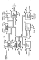
    • Figure 1 is a block diagram of the word processing system embodying the present invention.
    • Figure 2 is a block diagram further defining the processor shown in Fig. 1.
    • Figure 3 shows the organization of text within a document on a Direct Access Storage Device (DASD) such as a diskette or hard disk. Each document or other large grouping of information on the DASD is known as a data set.
    • Figures 4A-C show an example of a data set index for a relatively small data set, where the data set index contains only a root/leaf index node.
    • Figures 5A-B show an example of a data set index for a somewhat larger data set, where the data set contains a root node and two leaf nodes.
    • Figure 6 is a block diagram of an example of a data set index which contains a root node, two intermediate nodes, and many leaf nodes.
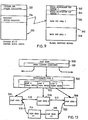
    • Figure 7 is a block diagram of an example of the relationships between volume and data set indexes. It is an extension and generalization of Figures 4-6.
    • Figure 8 is a diagram further defining the Storage Access Method (SAM) Internal Control Block shown in Figure 1.
    • Figure 9 is a diagram further defining the SAM Interface Control Blocks shown in Figure 1.
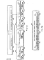
    • Figures 10A-B are block diagrams showing more details regarding the media control record and volume anchor when recorded redundantly. Details of the data set profile are also provided, indicating especially the leaf node shadow indicator and the data set status.
    • Figures 11A-B are flow diagrams showing the operational steps of the present invention with respect to Read and Write Index Nodes, showing how shadowed index nodes are managed.
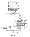
    • Figures 12A-B are flow diagrams showing the operational steps of the present invention with respect to Open and Close Data Set, data set status checking and management.
    • Figure 13 is a block diagram of an example of a three-level data set index in which a split operation at the leaf level was interrupted by an external system power failure before the new leaf nodes could be reflected in the intermediate node.
    • Figure 14 is a block diagram showing the significant procedures in the volume recovery process, and the relationships between the individual procedures.
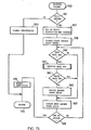
    • Figure 15 is a flow diagram showing the operational steps of the present invention with respect to the Recover Volume procedure.
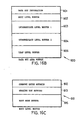
    • Figure 16A is a flow diagram showing the operational steps of the present invention with respect to the Recover Data Set procedure. Figures 16B-C are block diagrams showing more details of the data set recovery area buffer introduced in Figure 9, with further details provided on the contents of the root level buffer in the data set area buffer. Figure 16D is a flow diagram showing the operational steps of the present invention with respect to the Recover Root procedure.
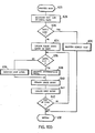
    • Figures 17A-B are flow diagrams showing the operational steps of the present invention with respect to the Recover Leaf Level and Backscan procedures. Figure 17C is a block diagram showing more details of the leaf level recovery area buffer introduced in Figure 16B.
    Description of the Preferred Embodiment
  • Referring now to Figure 1, there is shown a word processing system 10 which includes a keyboard 12 for receiving text and operator commands and transmitting the input through a channel 14 to a processor 16. A memory bus 18 is connected to the processor 16 as well as to a CRT display 20, one or more Direct Access Storage Devices (DASD) 22, a printer 24, and a system memory 26.
  • An operator enters a text stream through the keyboard 12 and each page of text is stored and processed in the memory 26. As the text stream is received in memory 26, it is also presented on the display 20. After the text has been entered into the keyboard 12, it can be stored on the DASD 22 or printed out on the printer 24.
  • The memory 26 includes a number of data areas and functional programs for operating with the text stored in the system 10. The text and related control functions are stored in a text storage buffer (TSB) 28.
  • A TSB control block 30 serves as the data area for the TSB 28. Block 30 is connected through a channel 32 to the TSB 28.
  • As each character is input through the keyboard 12, it is received at the memory 26 through a collection of keystroke service routines 34. A keystroke control block 36 is a data area which determines the selected keystroke routine for processing the received character. Block 36 is linked to the keystroke service routines 34 through channel 38. The keystroke service routines block 34 is further linked through a channel 40 to the TSB 28 and through a channel 42 to the TSB control block 30.
  • When the TSB control block 30 indicates that text must be moved into or out of TSB 28 this movement request is communicated to the storage access method (SAM) routines 44 via channel 46. The SAM routines 44 serve to control all data movement between the DASD 22 and memory 26. (Corresponding access method routines for the keyboard 12, display 20, and printer 24 are substituted for block 44 when communication with these units is required.) The keystroke service routines 34 communicate further control information and data to the SAM routines 44 through channel 48 to the SAM interface control blocks 50. (Corresponding access method interface-control blocks for the keyboard 12, display 20, and printer 24 are substituted for block 50 when communication with these units is required.) Upon completion of the SAM service request the SAM interface control blocks 50 will contain further information and data to be used by the keystroke service routines 34 for continued processing. The SAM blocks 50 are connected to the SAM routines 44 by a channel 52.
  • A SAM block 54 is connected via channel 18 with the DASD 22. This block serves as the transfer point for data transfers between the DASD 22 and memory 26. (Corresponding blocks for the keyboard 12, display 20, and printer 24 are substituted for block 54 when communication with these units is required.) The SAM block 54 is connected to the TSB 28 through channel 56. The SAM routines 44 can access data in the SAM block 54 through a channel 58. Block 54 is linked to the SAM interface control blocks 50 through a channel 60 for the purpose of communicating information and data to the keystroke service routines 34.
  • A SAM internal control block 62 is provided to contain the current status and information regarding the DASD 22. (Corresponding blocks for the keyboard 12, display 20, and printer 24 are substituted for block 62 when communication with these units is required.) Information is transferred between the DASD 22 and block 62 through the SAM block 54 by a channel 64. Information in the SAM internal control block 62 is communicated to and managed by the SAM routines 44 through a channel 66. Block 62 serves to store flags and status information as required by the operation of blocks 44 and 54.
  • The normal operation of the word processing system 10 is now briefly described with reference to Figure 1. As the operator enters each keystroke at the keyboard 12 a corresponding signal is transmitted through channel 14 to the processor 16 which enters the keystroke command into the memory 26. Upon receipt of the keystroke command a keystroke routine is produced for block 34 to handle the particular command received. The keystroke command is processed according to whether it is a control command or a graphic entry, and the result of the keystroke processing is entered into the TSB 28. As graphics and commands are built up in the TSB 28 the text information is presented at display 20. When the TSB 28 is in danger of being insufficient to hold the necessary text and commands, the keystroke service routines in block 34 will store control information in the SAM interface control blocks 50 to cause the SAM routines 44 to transfer blocks of information (in units called records) to the DASD 22.
  • Through control commands the operator can transfer information between the memory 26, display 20, DASD 22, and printer 24. Selected pages can be called up from the DASD 22 into the memory 26 so that the operator can make changes and corrections to the text and then re-enter the corrected text into the DASD 22 or have the corrected text printed at the printer 24.
  • Referring to Figure 2, the processor 16 is shown in further detail to illustrate typical hardware elements as found in such processors. The processor can be a commercially available unit, such as an Intel Corporation microprocessor identified by the model number 8086.
  • Such a processor includes a control unit 80 which responds to interrupts on a device bus 82 from the keyboard 12, the DASD 22, or the printer 24. The control unit 80 is also connected to an internal bus 84 for data and address which is interconnected to various other units of the processor 16.
  • In response to an instruction fetched from the memory 26, the control unit 80 generates control signals to other units of the processor 16. These control signals are interconnected to the various units by means of a control line 86 which is illustrated directly connected to an arithmetic logic unit (ALU) 88 and identified as a "control" line 86 to other units of the processor. Synchronous operation of the control unit 80 with other units of the processor 16 is achieved by means of clock pulses input to the processor from an external clock source (not shown). The clock pulses are generated by the external clock and transmitted through a bus 90 also shown interconnected to most of the other units of the processor detailed in Figure 2.
  • Data and instructions to be processed in the processor 16 are input through a bus control unit 92. Data to be processed may also come from a program I/0 control unit 94. The bus control unit 92 interconnects storage elements of memory 26 and receives instructions for processing data received from the input/output control unit 94 or received from the memory 26. Thus, the I/0 control unit 94 receives data from the keyboard 12 or the DASD 22 or the memory 26 while the bus control unit receives instructions and/or data from the same memory. Note, however, that different storage sections of the memory 26 are identifiable for instruction storage and data storage.
  • Device control information from the processor 16 is output through the program I/0 control unit 94 over an input/output data bus 98. Input data on the data bus 98 from the keyboard 12 or other device is processed internally through the processor by instructions through the bus 84 to the control unit 80 by the ALU 88. The ALU 88, in response to a control signal on line 86 and in accordance with instructions received on the memory bus 18, performs arithmetic computations which may be stored in temporary scratch registers 102.
  • Various other transfers of data between the ALU 88 and other units of the processor are, of course, possible. Such additional transfers may be to a program counter 104, a data pointer register 106, a stack pointer register 108, or a status register 110 by means of an internal bus 84. The particular operation of the processor is determined by instructions and data on the memory bus 18 and input data on the bi-directional bus 98. As an example, in response to received instructions, the processor transfers data stored in the scratch registers 102 to any one of the registers 106, 108, or 110. Such operations of processors as detailed in Figure 2 are considered to be well known by one of ordinary skill in the data processing field. A detailed description of each operation of the processor of Figure 2 for the described invention is not deemed necessary for an understanding of the invention as claimed.
  • Pages stored in the storage media on the DASD 22 are partitioned into records, which are units of text of convenient size. Records have a maximum size. Pages thus consist of at least one and possibly more records. The number of records in a page and the number of pages in a document are indefinite, and are constrained only by the capacity of the storage volume to store the data set. A data set in the word processing system 10 must be stored on the DASD 22 (a single diskette or a hard disk). If a document being entered into the system 10 is too large for a single diskette, the operator must terminate the entry operation for the current diskette or hard disk and must continue the document in a different data set on another diskette.
  • The storage media on the DASD 22 is partitioned into sectors in a manner that is well known in the art. The concept of a sector is considered to be well known in the art and, hence, a detailed description of the concept of sectoring is not deemed necessary for an understanding of the invention as claimed. In the word processing system 10, each sector on the storage media is assigned a unique logical sector number (LSN), where logical sector numbers are consecutive non-negative integers beginning with 0. The physical location on the storage media which corresponds to a particular logical sector number is not important to the understanding of the invention as claimed, as long as each logical sector number corresponds to one and only one physical area on the storage volume. Logical sectors are considered consecutive when their logical sector numbers are consecutive integers.
  • Referring to Figure 3, an example of a text document is shown as it is organized into a data set 120 on the DASD 22. The data set 120 in this example consists of a data set index 122 and three text pages, viz. a page 1 (124), a page 2 (126), and a page 3 (128). Page 1 (124) has three records, viz. a record 0 (130), a record 1 (132), and a record 2 (134). Page 2 (126) is small enough to be contained in a single record 0 (126). Page 3 (128) requires two records, namely record 0 (136) and record 1 (138).
  • A data set index 122 is the means whereby the SAM routines 44 determine where on the storage media the data set pages are located. The data set index 122 contains one index entry for each page of the document, viz. page 1 index entry 140, page 2 index entry 142, and page 3 index entry 144.
  • In order to facilitate locating the desired page quickly, each page index entry contains a key which identifies the page which is referenced by the entry. Thus for page 1 (124) there is a page 1 key 146, for page 2 (126) there is a page 2 key 148, and for page 3 (128) there is a page 3 key 150. To locate page 2 (126), page 1 index entry 140 may be determined to be inappropriate simply by comparing the page 1 key 146 with the key of the desired page. In the word processing system 10, all page keys within a data set index must be unique.
  • The data for each record of a page is located through the index entry by means of a record descriptor. Each record is stored on the storage volume in a set of consecutive logical sectors. The number of logical sectors allocated to a record corresponds to the minimum number of sectors required to contain the record. Only whole sectors are allocated. The record descriptor contains the location on the storage media of the logical sector containing the record whose logical sector number is numerically lowest. The record descriptor also contains the length of the record. In Figure 3, for example, the record descriptor for page 1 record 0 (130) is found in page 1 index entry 140 record 0 descriptor 152. The remainder of page 1 (124) is described in record 1 descriptor 154 and record 2 descriptor 156. The single record containing page 2 (126) can be located on the storage media by record 0 descriptor 158 in page 2 index entry 142. Page 3 index entry 144 similarly contains record 0 descriptor 160 and record 1 descriptor 162 pointing to page 3 record 0 (136) and page 3 record 1 (138), respectively.
  • he data set index 122 of a data set 120 stored on the DASD 22 of system 10 Ls partitioned into index nodes. Each index node is stored in one logical sector. If additions of text to the data set cause the amount of information in one of the index nodes to grow beyond that which can be stored in one logical sector, the index node is partitioned into two or more index lodes, so that each resulting index node can be contained within one logical sector. Every data set has at least one index node.
  • For every data set there is one unique index node called the root node. Also, index nodes whose index entries refer directly to pages are called leaf nodes. Figure 4A shows an example in which a data set index is small enough that the single leaf node needed and the root node are the same node, called the root/leaf node 170. Root/leaf node 170 contains a node header 171, data set profile 172 and an index element component 173. The data set profile 172 contains information and status relating to the data set as a whole. A data set name 174 contains the text graphics by which the operator selects the document for access. A data set comment 175 provides more space for descriptive information about the document which the operator does not wish to have as part of the data set name 174.
  • Figure 4B is a diagram providing more detailed information about the index element component 173 of root/leaf node 170. A leaf node index element component 173 contains the index entries which point directly to pages of the document. Leaf node index element component 173 in this example contains among other index entries a page N1 index entry 176 and a page N2 index entry 177, where N1 and N2 represent the page numbers of a pair of consecutive pages in the document, and page N1 comes before page N2. Page N1 index entry 176 contains a page N1 key 178 and one record descriptor for each record in page N1 among which are a record 0 descriptor 179 and a record 1 descriptor 180. Similarly, page N2 index entry 177 contains a page N2 key 181, a record 0 descriptor 182 and a record 1 descriptor 183.
  • Within an index element component, index entries are stored in order of ascending page keys in such a way that if page N2 immediately follows page N1 in the document, page N2 index entry 177 will immediately follow page N1 index entry 176 if both page N1 and N2 are referenced within the same leaf node.
  • Figure 4C provides more detail regarding the node header 171 shown in Figure 4A. The node header 171 provides information regarding the index node 170 as a part of a data set index. The format shown in Figure 4C is common to all index nodes, though the contents of the various fields may differ from data set to data set and between index nodes within the same data set. A node length 184 contains the overall current length of usable data in the index node. The difference between the node length value and the DASD 22 sector size shows the amount of space remaining before the index node is full.
  • An object identifier (ID) field 185 shows the type of data set to which the index node belongs. The object ID 185 is comprised of two portions: an object attribute 186 and an object type 187. The object type 187 shows the general type of data set. For example, all text documents have the same object type. The object attribute 186 shows whether the index node belongs to a low-level data set or an index of data sets (called a directory).
  • A node hierarchy 188 indicates the type of index node. The various types of index nodes are: root node (primary data set node), leaf node (points directly to data set records), root/leaf node (combination of root and leaf), and intermediate node. Figure 4A would indicate root/leaf for the small data set assumed for that example.
  • A node level 189 indicates the level the node occupies in the data set. A leaf node always has a node level value of 0. This applies also to the root/leaf node, since that node is simultaneously a root node and a leaf node. If the data set is large enough that multiple index nodes are required, the node level for any node in the index indicates the distance from the leaf level. The node level of the root thus always indicates the maximum number of levels in the data set, since the SAM routines 44 always ensure that there are an equal number of levels from the root node to any leaf node.
  • A tree ID 190 is the final portion of the node header. The tree ID 190 contains a data set ID which is unique to that data set on that storage volume. All index nodes within the same data set have the same tree ID, and index nodes belonging to a different data set will have a different tree ID. Tree ID's are assigned at the time the data set is created and are not reassigned as long as the same data set exists on the same DASD 22.
  • As the operator causes more text records and pages to be added to the document, root/leaf node 170 will eventually have insufficient room in index element component 173 for the next entry. Figure 5A illustrates the result of partitioning root/leaf node 170 into a root node 200, a leaf node A (202), and a leaf node B (204). Root node 200 now contains a data set profile 172 the same as in root/leaf node 170 and a root/intermediate index element component 216. Leaf node A (202) has as major components a leaf node chain 206 and an index element component 208. Leaf node B (204) has as similar major components a leaf node chain 210 and an index element component 212. Referring briefly to Figure 4C, the node level 189 value for the root node 200 in Figure 5A would be 1. The node level value for both leaf nodes 202 and 204 would be 0.
  • The index element components 208 and 212 of leaf node A (202) and leaf node B (204) together contain the same information as was in the index element component 173 (as detailed in Figure 4B) of root/leaf node 170 in Figure 4A. In the example of Figure 5A, it is assumed that the index element component 173 has been split among index element components 208 and 212 such that the index entries for page N1 and all prior pages are stored in index element component 208 of leaf node A (202), and the index entries for page N2 through page z (the last page of the document) are stored in index element component 212 of leaf node B (204). This implies that the page N1 index entry 176 is the last index entry in index element component 208, and page N2 index entry 177 is the first index entry of index element component 212. Since page z denotes the last page of the document in this example, the page z index entry 214 is the last index entry of index element component 212.
  • Figure 5B is a diagram showing more detail for root/intermediate index element component 216 of root node 200. Since there are two leaf nodes in Figure 5A, there are two index entries in root/intermediate index element component 216. Leaf node A index entry 224 contains the page N1 key 178 and a leaf node A LSN 226 containing the logical sector number of leaf node A (202). Likewise, a page z key 228 and a leaf node B LSN 230, containing the logical sector number of leaf node B (204), are contained in a leaf node B index entry 232.
  • Note that unlike the record descriptors of Figure 3, the leaf node index entries 224 and 232 do not contain values for record or index node lengths. Since index nodes are always a single logical sector, and since the root/ intermediate index element component 216 always refers to index nodes (leaf nodes in Figure 5A), the length of the referenced index nodes is always the same and can be omitted from the index entry.
  • Note also that the index structure illustrated in Figures 5A-B allows quick selection of the proper leaf node for a particular desired page. While searching the index element component of the root node, comparing the key of the desired page with the keys of the index entries, the first index entry in the root node 200 containing a page key equal to or higher than the key of the desired page refers to the leaf node which must contain the index entry that locates the desired page if the desired page exists in the document.
  • To facilitate sequential viewing and revision of the document (commonly called scrolling through the document in the data processing field), leaf node chains are provided so that the next leaf node (or prior leaf node) may be located without reference to the root node of the document when the point of viewing or revision reaches records referenced at the end of the index element component for the appropriate leaf node. Leaf node chain 206 of leaf node A (202) contains two logical sector numbers (LSNs): a prior leaf LSN 217 and a next leaf LSN 218. In the example of Figure 5A, there is no prior leaf for leaf node A (202), since leaf node A (202) contains the index entry for the first page of the document, so the prior leaf LSN 217 would be set to a value that may be recognized as_an invalid logical sector number by the SAM routines 44. The next leaf LSN 218 of leaf node A (202) contains the logical sector number of leaf node B (204). In a similar manner, prior leaf LSN 220 in leaf node chain 210 of leaf node B (204) contains the logical sector number of leaf node A (202). Likewise, since leaf node B (204) contains the index entry for the last page of the document, the next leaf LSN 222 contains the invalid logical sector number value.
  • The root node 200 is the starting point of the index of the data set. Therefore, root/intermediate index element component 216 contains index entries which allow leaf node A (202) and leaf node B (204) to be located on the storage volume. In leaf node A (202), page N1 index entry 176 references the last page referenced by leaf node A (202). This means that the page N1 key 178 (Figure 4B) is the arithmetically greatest key in index element component 208. This is called the high key for the leaf node A (202). Similarly, the key in page z index entry 214 is arithmetically greater than the keys for all other index entries in index element component 212 of leaf node B (204), so the page z key 228 is the high key for leaf node B (204).
  • Insertions of index entries for new pages or additions to existing index entries for new records always occur in a leaf node. As a consequence of this, it may happen that an existing leaf node contains insufficient space when adding a new record or page. The leaf node with insufficient space is then replaced with two leaf nodes, in a storage access method operation called a split. The root node index element component contained a single index entry for the leaf node prior to the split (leaf node B index entry 232, for example). This index entry must be replaced by two index entries, one index entry for each of the two new leaf nodes. This operation is a simple extension of the operation of splitting a root node into a root and two leaf nodes, and the operation will not be illustrated with a separate diagram.
  • As the operator enters the graphic characters and commands for a very large document, enough new leaf nodes may be added so that there is not enough space in the root node index element component 216 for another leaf node index entry. At this time the root node 200 must be split again. Because the root node 200 is referring to leaf nodes, new leaf nodes cannot be created (leaf nodes do not refer to other leaf nodes outside the leaf node chains). Instead, another type of node is created called an intermediate node.
  • Referring to Figure 6, the root node 200 from Figure 5A has been replaced with a root node 240 containing a root/intermediate index element component 242 which has the same structure as that shown by Figure 5B. However, instead of containing leaf node logical sector numbers, the index entries in index element component 242 contain the logical sector numbers of intermediate node I (244) and intermediate node J (246). Within intermediate node I (244) there is an index element component 248 containing a leaf B index entry 250, a leaf C index entry 252, and a leaf D index entry 254 which refer to leaf node B (256), leaf node C (258), and leaf node D (260), respectively. The index entries in index element component 248 have exactly the same structure as leaf node A index entry 224 in Figure 5B. Figure 6 thus shows an example of a 3-level index tree, where the node level of root node 240 would be 2, the node level values for intermediate nodes I (244) and J (246) would be 1, and the node level values for all leaf nodes would still be 0. The index element component 262 in intermediate node J (246) is structured in the same way as index element component 248.
  • The connections 264 between adjacent leaf nodes in Figure 6 are a representation of the leaf node chain such as leaf node chain 206 and leaf node chain 210 in Figure 5A.
  • Figure 6 thus shows an example of a general index structure which allows the SAM routines 44 to locate a desired page or record in two different ways, depending on the manner of viewing or revising the document. In order to locate the first record of a page referenced in leaf node D (260), the SAM routines 44 would fetch the root node 240 from the DASD 22 and would search the root index element component 242 to determine that intermediate node I (244) is the appropriate intermediate node. Intermediate node 244 would then be fetched from the storage media and the leaf node D (260) is similarly selected as the proper leaf node. After fetching leaf node D (260) from the storage media, the index element component of leaf node D (260) is searched to locate the key of the desired page.
  • On the other hand, if the operator is at the end of the last record referenced in leaf node C (258) and desires to scroll into the next record of text, which is referenced in leaf node D (260), the leaf node chain in leaf node C (258) can be used directly to locate leaf node D (260) on the storage media without requiring that the root node and an intermediate node be fetched and searched again.
  • The index structure shown as examples in Figures 4-6 can be generalized from a single data set to an entire volume, by constructing the volume as a hierarchy of indexes. Figure 7 shows a block diagram of an example of a volume index. In this example, the storage volume contains three data sets. Two of the data sets have the same data set type (for example, both are text documents). The third data set has a different data set type.
  • For each storage volume, there is a media control record 280 which contains information about the volume as a whole, such as volume label (volume name). Within the media control record 280 there is a field called a HDR1 field 281. The purpose of the HDR1 field 281 is to provide information about the data residing on the volume. In particular, there is an anchor location pointer 282 (symbolized by a curved arrow from the media control record 280 to the anchor 284). The anchor location pointer 282 serves to show the location on the volume of an anchor 284.
  • The anchor 284 is the first level of volume index information. The function of the anchor 284 is similar to the volume table of contents on a DASD in a data processing system. In the word processing system 10, the anchor 284 is structured as a data set index. In particular, the format of the anchor is that of a root/leaf node, an example of which is shown in Figure 4A. However, instead of referring to records and pages of a document as in Figure 4A, the anchor 284 refers to volume information or other data sets. As with other index nodes, the anchor 284 contains an index element component 285 which refers to the lower-level data.
  • The format of the anchor index element component 285 is similar to the index element component 173 shown in Figure 4B. In the anchor 284, the key of the index entry (similar to the page N1 key 178) is constructed from data set type. Thus, there is one index entry in the anchor 284 for each unique data set type existing on the storage volume.
  • A media allocation map 286 provides an indication of the allocation status of each sector on the storage media. In word processing system 10, the media allocation map contains one indicator for each sector on the media. The indicator shows whether or not the sector is available for allocation to a data set. The indicators for all existing index nodes and data set records indicate not available; in other words, these sectors have already been allocated. Media allocation techniques of this kind are considered to be well known in the art, and a detailed knowledge of the actual techniques used for managing the media allocation map contents in word processing system 10 is not deemed necessary for an understanding of the invention. The index entry for the media map 286 in the anchor index element component 285 has as the key the unique data set type assigned to the media allocation map, and has as the record descriptor (refer to Figure 4B record descriptor 179) the logical sector number 287 and length of the media allocation map 286 on the volume.
  • In the example provided by Figure 7, it is assumed that data set A (288) is the only data set of its type on the volume. Therefore, the index entry in the anchor index element component 285 consists of a key constructed from the data set type of data set A (288) and a logical sector number 289 showing the logical sector number of the root node of data set A (288).
  • Data set B (289) and data set C (290), however, are assumed to have the same data set type. Since the keys in an index element component must be unique, and since keys constructed from the data set types of data set B (289) and data set C (290) would be equivalent, another level of index is introduced to provide for this requirement. A directory 291 is a data set index the data for which consists of lower-level data sets. The data set type of directory 291 is the same as the data set type of all data sets to which it refers. Therefore, the index entry in anchor index element component 285 uses a key derived from the data set type of directory 291 and refers to the directory root node via a logical sector number 292.
  • The directory index element component 293 refers to data set root nodes. The keys for index entries in index element component 293 are the names of the data sets (as contained in the data set profile 172 of the root node of each data set, referring briefly to Figure 4A). In word processing system 10, data sets on a single storage media are required to have unique data set names. Thus, the keys in directory index element component 293 are unique.
  • Like all other data set indexes, directory 291 may be expanded to multiple levels as the number of data sets is increased to the point that a single root/leaf is not sufficient to contain the index entries for all data sets of that data set type. Since the number of unique data set types in word processing system 10 is limited, however, it is never necessary to expand the anchor 284 larger than a root/leaf.
  • Figure 8 provides more detail regarding a part of the SAM internal control block 62 shown in Figure 1. A unit control block/storage (UCS) 300 contains device and operation status and control information and provides buffer areas for the access and updating of data set and volume indexes. The term volume refers to a DASD 22 such as a single diskette or a hard disk file attached to the word processing system 10. Each volume available for processing by the system has its own UCS.
  • A device status information area 302 contains data and control indicators used by the SAM routines 44 to control the actual I/0 operations to the DASD 22. Device status information 302 is also used by the SAM routines 44 to determine which of the available volumes should be accessed during the processing of a request from the keystroke service routines 34.
  • A volume data set index buffer 304 contains the first level of volume index called an anchor. This buffer contains the anchor 284 in Figure 7 for the volume in the DASD 22. The anchor is retained in the memory 26 in order to eliminate an input operation from DASD 22 when a data set must be located on the volume. Locating a data set on the volume is very similar to locating a page within a data set, where the keys in the volume index consist of the type of data set (text document, for example) and the data set name (as illustrated by data set name 174 in Figure 4A).
  • Index node buffer 1 (306), index node buffer 2 (308), and index node buffer 3 (310) are buffer areas in which data set index nodes or volume index nodes are processed between transfers to and from the DASD 22. Each index node buffer can contain one index node. More than one buffer is provided to facilitate index searches and split operations.
  • A media allocation map buffer 312 provides space for the media allocation map for the storage volume. This buffer will contain a copy of the media allocation map 286 (refer to Figure 7) for the volume in the DASD device 22.
  • The rest of the UCS 300 is used for internal status and control information and to contain the results of various intermediate calculations and operations, a detailed explanation of which is not deemed necessary for an understanding of the invention.
  • Figure 9 is a block diagram providing further details of the SAM interface control blocks 50 in Figure 1. The major operations provided by the SAM routines 44 covered by the invention are Open data set for access, Read one or more records from the DASD 22 into the memory 26, and Write one or more records from the memory 26 to the DASD 22.
  • For each service requested of the SAM routines 44 by the keystroke service routines 34, a storage event control block 330 (SECB) is required. The area in the memory 26 that is actually allocated to the SECB 330 is determined by the keystroke service routine making the request. Channel 46 in Figure 1 is used to pass the location of the SECB 330 to the SAM routines 44.
  • Within the SECB 330 can be found all the information necessary for the SAM routines 44 to initiate the particular operation requested. A command and option indicators area 332 provides the indication of the major operation command requested (Recover volume, for example) and the command options which may modify the request. Command and option indicators 332 is used to produce a SAM service routine to process the particular command.
  • A recovery buffer location 334 contains the location in the memory 26 of a global recovery buffer 340. As with the SECB 330, the area in the memory 26 actually allocated to the global recovery buffer 340 is chosen by the keystroke service routines 34. The global recovery buffer 340 is used by the SAM routines 44 when it is necessary to verify or reconstruct the volume and data set indexes following an error situation.
  • In the protection and recovery of data sets and data records on a storage volume, there are two distinct phases: precautions taken to prevent loss of data due to media errors and the scanning of data set and volume indexes when a possible fault has been detected.
  • Media errors are detected when an attempt is made to fetch data and the data cannot be verified as valid by the system 10. Media errors in the system 10 consist of those errors common to the DASD 22, and may occur due to media surface contamination, media wear, and so on.
  • In the word processing system 10, the mechanism to protect against severe loss of data due to media errors is the recording of an extra copy of critical data on the volume. This is known as redundant recording. It is possible to record two copies of every piece of data to be stored on the storage volume. This has the disadvantage of reducing the effective capacity of the storage volume to half the actual capacity. Therefore, in the word processing system 10, a subset of the total information recorded is designated critical information which must be protected through redundant recording. Critical information is information the loss of which would require significant effort on the part of the operator to re-create or re-enter into the system.
  • Realizing that not all information can be designated critical without reducing the effective capacity of the volume, the first rule applied in word processing system 10 is that data records in a data set are not critical information. The loss of an individual data record would normally require only a little effort to recover by entering the data again via keyboard 12 in the normal entry manner. Therefore, only data set index nodes or volume index nodes may be considered critical.
  • Referring to Figure 7, if the media control record 280 cannot be fetched successfully, the anchor and all data sets cannot be located. Therefore, the media control record 280 is considered critical. In word processing system 10, the media control record is always recorded at logical sector number 0 and logical sector number 17. These logical sector numbers are independent of device type (diskette or hard disk 22). The contents of the two copies of the media control record are identical.
  • Similar to the media control record, the anchor 284 is considered critical because failure to read the anchor means that none of the data sets can be located. Therefore, two copies of the anchor 284 are stored on each storage volume. The contents of the two copies of the anchor are identical. The location (logical sector number) of the primary and backup copies of the media control record must be known to the system 10 prior to the attempt to read the media control record. Since the media control record contains anchor location LSN 282, the anchor may be stored at any defect- free logical sector on the volume, and may be moved if an attempt to store an updated copy is not successful at the original logical sector; it is only necessary to alter the media control record to reflect the latest location of the anchor after such a location change.
  • In order to improve system performance, it is desirable to have both copies of redundantly-recorded information physically near each other on the volume, to minimize the time the read/record head of the DASD 22 is moving from one location to the other. On the other hand, it is desirable to have the two copies far enough from each other that a single defect or fault does not prevent access to both copies. Furthermore, the relative importance of each of the factors (performance, risk reduction) may be different for different storage volumes, depending on the contents of the volume.
  • Since the media control record is seldom accessed, this flexibility for it is not as important in word processing system 10. Therefore, the fixed location on all storage volumes was selected to reduce system logic complexity. In order to allow the location of the second copy of the anchor to be flexible, a second location area was added to the media control record to define the location of the backup copy of the anchor on the storage volume.
  • Figure 10A shows a block diagram of the media control record and anchor from Figure 7 with the backup copies. A media control record primary copy 360 is recorded at logical sector 0, with a backup copy 362 at logical sector 17. The primary copy HDRl field 364 and the backup copy HDR1 field 366 both contain the media location of the primary anchor 368. An additional field called the backup anchor pointer (BUAP) has been added in each media control record copy, viz. the primary copy BUAP 372 and the backup copy BUAP 374. Both contain the location of the backup copy of the anchor 370.
  • Referring to Figures 4-7, if the root node of a data set cannot be fetched successfully by the system 10, the data records in the data set cannot be located on the storage volume and the data is lost to the system operator. Therefore, all data set root nodes are considered critical and are recorded redundantly on the storage volume. This applies particularly to the root node of a directory, since the inability to access a directory root node implies that all data sets referenced by the directory (all data sets of that particular data set type) are lost to the system 10 and the system operator.
  • With respect to the directory 291 in Figure 7, if there are enough data sets of the same type that the directory becomes muli-level (as in Figure 5A or Figure 6), the loss of a leaf node in the directory index would mean that several data set root nodes could no longer be located. Thus, directory leaf nodes are also considered critical index nodes in word processing system 10.
  • Referring to the previous description of Figures 4B and 5B, in particular the description of the record descriptor 179 and leaf node LSN 226, the location of the lower level (data record or index node) is provided by logical sector number. When the primary copy of one of the above critical nodes cannot be fetched without error, the backup copy must be located. The performance of searching a data set index is related to the number of levels in the data set, and the number of levels is determined both by the number of data records in the data set and the size of the individual index entries. If an extra logical sector number were added to each of the index entries referring to critical sectors, this would mean that fewer records could be stored in a data set with a given number of levels. The index entries already contain the logical sector number of the primary copy. In word processing system 10, the backup copy is defined to be located at a fixed logical sector number offset from the primary copy. In other words, the arithmetic difference between the LSN of the backup copy and the LSN of the primary copy is fixed for the storage volume.
  • Referring to Figure 10A, in the anchor index element component 376 a shadow offset field 378 is defined. The shadow offset 378 is the difference in logical sectors between the logical sector number of the primary copy and the LSN of the secondary copy. Thus, if the volume anchor can be accessed, the logical sector number of a backup copy of a critical index node can be calculated by adding the shadow offset for the volume to the logical sector number of the primary copy. This allows the word processing system 10 to select the best shadow offset (based on performance and risk reduction factors) based on volume contents for different volumes. Since a copy of the anchor is available in memory 26 in the volume data set index buffer 304 of UCS 300 (Figure 8), the SAM routines 44 can always locate the backup copy of critical information as needed.
  • From the above discussion, all root nodes are considered critical sectors (redundantly recorded). Also, directory leaf nodes are critical sectors. Other leaf nodes may be considered critical, depending on the type of data set. For example, the leaf nodes of a text document could be considered critical, since a leaf node may refer to many pages of text in a document. On the other hand, the leaf nodes of a program data set on a program diskette for word processing system 10 would not be considered critical, since the loss of any program data invalidates the program diskette and since another program diskette may be ordered from the manufacturer with little effort on the part of the system operator. Thus, some leaf nodes are considered critical and others are not, depending on the contents of the data set.
  • Figure 10B provides more detail regarding the data set profile 172 of the root node 170 shown in Figure 4A. Within the data set profile 390 there are four components: a data and index attributes component 392, a data set name 393, a data set comment 394, and a data set status 395. The data and index attributes 392 contain the complete description for the SAM routines 44 of the structure of the data set index and the index entries within the index element component of the index nodes. In particular, a leaf shadow indicator 397 specifies whether or not the leaf nodes for this particular data set should be recorded redundantly. Thus, whether leaf nodes are critical or not may be specified for each particular data set. In word processing system 10, the keystroke service routines 34 generally treat any data set of a given type the same as all other data sets of the same data set type. Thus, all text documents would have their leaf nodes shadowed (recorded redundantly). Within the SAM routines 44, all directory data set roots specify that leaf nodes should be shadowed.
  • A logical operation of the present invention with respect to Read index node is illustrated in the flow diagram shown in Figure 11A. The procedure is started with the read index node service routine step 400. In step 402 the primary copy of the index node is read, using the logical sector number supplied by the procedure which caused the read index node procedure to be performed. If the check in step 403 determines that the index node was fetched successfully from the DASD 22, an indication of successful index node read completion is returned via a return code in step 405 and the procedure is terminated in step 407 until the next read index node is required. The return code means is a concept that is considered well known in the art, and understanding the exact mechanism is not deemed necessary to the understanding of the invention.
  • If an error was detected in step 403, the type of index node expected is examined in step 409. If a root node was expected, it was recorded redundantly initially, so the LSN of the shadow copy is calculated in step 411 by adding the volume shadow offset to the LSN of the primary copy, and the shadow copy is read in step 413. If no error in the fetch of the shadow copy is detected in step 414, an indication of successful read is returned in step 405 and the procedure is terminated in step 407 as before. If an error was detected in step 414, an indication of read error is signalled via return code in step 416 and the procedure terminates in step 407 as above.
  • If the expected index node is not a root node according to step 409, the expected node is checked in step 418 to see if a leaf node was expected. If not (intermediate node expected), an error indication is returned in step 416 as above since the primary copy could not be read successfully in step 402. The same is true if it is found in step 420 that the expected leaf node is not shadowed in the current data set (according to the leaf shadowed indicator 397 in the data set profile 390 of Figure 10B). For expected leaf nodes which are shadowed, the procedure is the same as for a root node expected, with a read of the shadowed copy in steps 411 and 413.
  • Figure 11B shows a flow diagram illustrating a logical operation of the present invention with respect to Write index node. The procedure is started with the write index node service routine step 425. In step 427 the primary copy of the index node is written, using the logical sector number supplied by the procedure which caused the write index node procedure to be performed. If the check in step 429 determines that the index node is a root node, or if it is found in steps 431 and 433 that the index node is a leaf node and the data set profile shows that the leaf node should be shadowed, the LSN of the shadow copy is calculated in step 435 by adding the volume shadow offset to the LSN of the primary copy, and the shadow copy is written in step 436. The procedure is then terminated in step 438 until the next request for write index node is received.
  • If it is found in steps 429 and 431 that the index node is not a root and not a leaf node, or if the check in step 433 shows that the leaf nodes should not be shadowed in the current data set, the procedure is simply terminated in step 438 as above, since the primary and only copy was written in step 427.
  • The structures shown as examples in Figures 10A-B and the procedures illustrated in Figures 11A-B indicate how the word processing system 10 provides a flexible means of reducing the risk of significant loss of data for the system operator with minimum loss in storage capacity of the storage volume, while at the same time removing the absolute dependency on error-free operation on any one physical sector on the storage media.
  • During normal processing of word processing system 10, the SAM routines 44 assume that the data set index structures are complete and correct. If there are no storage media errors and no abnormal system terminations, this assumption is sufficient to assure proper access to any data set available on the DASD 22.
  • With the storage media used in the DASD 22, however, it is possible that data once successfully stored on the storage volume may not be accessed due to media errors. Referring to Figure 6, if data records whose index elements lie in the index element component of leaf node C (258) are to be accessed, this normally requires scanning the root node 240; locating, fetching and scanning intermediate node I (244); and locating, fetching and scanning leaf node C (258) before the data records may be located and accessed on the storage volume.
  • The structures and procedures illustrated in Figures 10 and 11 greatly reduce the risk of being unable to access the root node or leaf nodes due to media error. However, the intermediate nodes are not protected via shadowing. Note that if any leaf node can be located, any other leaf node can also be located via the leaf node chains 264 in Figure 6. If a read error was detected in the fetch of intermediate node I (244), it would still be possible to fetch intermediate node J (246), then fetch leaf node F (266), then successively locate the prior leaf nodes via the prior LSNs 217 of the leaf node chains 206 (refer briefly to Figure 5A) until leaf node C (258) is located.
  • To add general procedures to accomplish such an alternative scanning to the SAM routines 44 would greatly increase the complexity of the normal processing routines. It would also increase significantly the storage requirements in the memory 26. Since the total amount of the memory 26 is limited in word processing system 10, it is better to limit the size and complexity of the SAM routines 44.
  • A general overview of the media error approach adopted in word processing system 10 is as follows. Referring briefly to Figure 10B, every data set root node contains a data set profile 390. One of the components of the profile 390 is a data set status component 395. In word processing system 10, the data set status may be one of three different states: Closed, Open Update, and Damaged.
  • Similar to most storage access methods for DASD in the data processing field, keystroke service routines 34 must present an Open request to the storage access method for a data set before issuing requests for access to data set records. Figure 12A shows a flow diagram illustrating a logical operation of the present invention with respect to Open status check.
  • The procedure is started with the open status check service routine step 450. In step 451 the read index node procedure is performed to read the data set root, and the data set status in the data set profile is located in step 453. If the data set status indicates in step 454 that the data set is not closed, the data set is not guaranteed correct. Therefore, an indication of data set unavailable is signalled via a return code in step 456 and the procedure is terminated in step 458 until the next open status check is required.
  • If it is found in step 454 that the data set current status is closed and thus allows access, the access request type is tested in step 460. If the request type is not for update (update means that the data set index and/or one or more records may be altered via addition, replacement, or deletion), an indication of data set available is returned in step 462 and the procedure is terminated in step 458 as before. If the request is for update access, the current data set status is altered in step 464 to open update and the write index node procedure is performed to write the root node onto the volume, in step 466, prior to the available data set termination in steps 462 and 458 as above.
  • Thus, the SAM routines 44 for Open will allow access to a data set only when no prior unresolved problems or errors have been detected in the data set.
  • After successful Open of a data set, normal operation of the system 10 proceeds assuming that all data set indexes are correct and that all index nodes can be read without error (with procedures for recovering from read errors of critical sectors in normal processing as illustrated in Figure 11A-B). If a requested index node or data logical sector is found to be unavailable due to media error during normal SAM routines 44 processing, an error indication is returned to the keystroke service routine 34. When the keystroke service routine 34 issues a request for Close, this error detection must be saved on the storage volume to protect against later access until the problem situation is resolved.
  • Figure 12B shows a flow diagram illustrating a logical operation of the present invention with respect to Close status. The procedure is started with the close status service routine step 475. In step 476 the data set status component 395 of the data set profile 390 (refer to Figure 10B) in the root node is located. If a prior data set error indication is found in step 478, the data set status is set in step 480 to the Damaged state and the write index node procedure is performed in step 481 to write the root node onto the volume. Thereafter, the procedure is terminated in step 483 until the next close status is required.
  • If no prior error was detected in step 478, the current data set status is checked in step 485. If the current access type is not update, the procedure is terminated in step 483 as above. If the access type is update, the data set status is altered in step 487 to the Closed state, the write index node procedure is performed in step 488 to write the root node onto the storage volume, and the procedure is terminated in step 483 as above.
  • With the procedures illustrated in the above discussion of Figures 12A and 12B, the SAM routines 44 prevent access to a data set which is likely to have unresolved problems, detect problems that cannot be resolved by normal processing procedures (errors that cannot be resolved by accessing a duplicate copy recorded redundantly on the media), and preserve an indication on the storage volume of unresolved problems detected in a data set.
  • In the normal operating environment of the word processing system 10, another situation may result in an incorrect data set index: an unanticipated power failure. If the external power supplied to the system 10 fails during the updating of an index, an incorrect data set or volume index -structure may result.
  • Figure 13 shows a block diagram of an example of a portion of a data set index similar to the one shown in Figure 6. A root node 500 contains, among other items, an index entry referring to an intermediate node I (502). Intermediate node I (502) refers to leaf nodes B (504), C (506), and D (508). Leaf node chains 510 and 512 serve the same purpose as leaf node chains 264 in Figure 6.
  • If records are added to the data set whose index entries should be stored in leaf node C (506), and sufficient records are added that leaf node C (506) does not have enough space for the index entries, two new leaf nodes must be created to replace leaf node C (506), namely leaf node C1 (514) and leaf node C2 (516). The leaf node chain joining leaf node B (504) and leaf node C (506) must be altered in leaf node B (504) to correspond with leaf chain 518. Similarly, leaf node D (508) must be altered so as to replace leaf chain 512 with leaf chain 520. Finally, leaf C index entry 522 in intermediate node I (502) must be replaced with two new index entries, one each for leaf node Cl (514) and leaf node C2 (516).
  • The process of writing the data records onto the storage volumes and reading and writing index nodes is not instantaneous. System external power may fail at any step in the index update process.
  • As an example, leaf nodes Cl (514) and C2 (516) have been stored on the volume. Leaf nodes B (504) and D (508) have had the leaf chains updated. However, before intermediate node I (502) can be altered and stored back on the volume, system external power fails.
  • When power is restored to the system 10, the data set index on the storage volume for the data set of root node 500 is incorrect. Leaf nodes B (504) and D (508) are chained to leaf nodes C1 (514) and C2 (516), respectievely. However, intermediate node I contains an index entry for leaf node C (506), which should no longer be a part of the data set index. It does not contain index entries for leaf nodes C1 (514) and C2 (516), which should be part of the data set index. Thus, the data set contains an unresolved problem.
  • The detection of such an unresolved problem is already incorporated in the structures and methods discussed in connection with Figure 12A. When the data set shown in Figure 13 was selected for update access (required prior to inserting new records in the data set), the open status check procedure illustrated in Figure 12A caused the data set root 500 to be written to the storage volume with a data set status showing a state of Update, in steps 464 and 466. After power has been restored to the system 10, further access is prevented by the open status check procedure due to the current data set status of Update until the (potential) problems with the data set index have been resolved.
  • Another unresolved problem exists on the storage volume after the external power failure situation discussed with Figure 13. Figure 7 shows a volume media allocation map 286 residing on the volume. For performance reasons, the copy of the media allocation map 312 in UCS 300 (Figure 8) is not stored on the volume for every allocation change, but is stored at discrete intervals when index and data set record changes have been completed.
  • In the example of Figure 13, the allocation indicators in the allocation map on the storage volume for the logical sectors containing leaf node Cl (514) and leaf node C2 (516) still indicate that the logical sectors are available for future allocation. If these sectors are later used to satisfy a request for allocation on the volume, different information may replace leaf node Cl (514), leaf node C2 (516), or both. In that case, all records whose index elements were in leaf nodes Cl (514) and C2 (516) would be lost for the operator.
  • A less critical problems exists in the case of the logical sector containing leaf node C (506), in that this sector still is shown as already allocated in the media allocation map on the storage volume. Since the information in leaf node C (506) is no longer needed, the logical sector containing leaf node C (506) should be available for future allocation.
  • The media allocation map problem discussed above pertains to the storage volume as a whole. In order to prevent loss of the new leaf nodes C1 (514) and C2 (516), update access must be prevented to the volume as a whole until the problem is resolved, since any request for new allocations of logical sectors on the volume will be done with respect to the single volume media allocation map.
  • Detection of the potential problem situation is performed by means of a volume update indicator in the volume anchor similar to the data set status in the data set root node. When a data set is requested for Open of type update, the status in the anchor is set to reflect this fact. As long as any data set is open for update, the anchor status reflects the update status, even if the original data set is requested for Close. Only when the last data set open for update access is closed will the anchor status be updated to reflect that the volume index (including the media allocation map) contains no detected unresolved problems.
  • Resolving potential problems detected via the mechanisms discussed above is called recovery. Recovery must be able to resolve problems caused by media errors in data set or volume indexes and problems caused by abnormal termination of system processing due to external system power failure. On any given storage volume, it is possible for examples of all problems discussed so far to exist at the same time.
  • In order to construct a media allocation map for the volume that accurately reflects the current state of logical sector allocation, it is necessary to locate all sectors that are actually allocated to a data set or to the volume indexes. This actually means examining all index entries in every index node that can be reached directly or indirectly by starting with the system anchor. Referring to Figure 7, this means locating all logical sectors allocated to one of the following: anchor 284, media allocation map 286, data set A (288), directory 291, data set B (289), or data set C (290). Referring to Figure 13, this also means that only the valid index nodes and data records of a data set are to be considered allocated, and leaf node C should not be considered a valid index node. Referring briefly to Figure 6, the existence of intermediate node J (246), leaf node F (266) and the leaf node chains 264 means that leaf node C (258) can be located indirectly even if intermediate node I (244) cannot be accessed successfully during recovery. As a part of recovery, the index entries lost when intermediate node I (244) was lost must be reconstructed in one or more similar existing or new intermediate nodes.
  • One aspect of recovery that is very important to the word processing system 10 is performance. It is vital to recover as much operator data as possible, using all sources of information made available by the structure of the volume indexes illustrated in Figures 4 through 7. On the other hand, the recovery procedures should complete as quickly as possible so that the system operator may continue with the more normal word processing tasks. In particular, the number of I/0 operations directed at the DASD 22 should be minimized. Since it is necessary to access all volume and data set index nodes at least once to reconstruct the volume media allocation map, where at all possible an index node should be read and written no more than once.
  • The SAM routines 44 in system 10 consist of general access method procedures designed to process a wide variety of data set and data content types. Since unique keystroke service routines already exist for processing the data records of each data set type, the recovery procedures in the SAM routines 44 need not process the actual data records. A data record can be located on the volume, and the logical sector numbers allocated to that record can be determined, strictly through access to the data set index nodes (leaf nodes), without actually accessing the data records. Therefore, the recovery procedures in the SAM routines 44 will not access (read or write), data records. The keystroke service routines 34 must examine data records in damaged data sets after the SAM routines 44 have resolved all problems in volume and data set indexes on the volume. However, only data records in possibly damaged data sets must be examined. In other words, data sets whose data set status in the root node indicated a Closed state at the start (and end) of the SAM recovery procedures need not have the data records examined by the keystroke service routines 34. There will normally only be one or two damaged data sets on a volume where data records must be examined and data problems resolved. This greatly enhances the performance of the overall data recovery process for the system operator.
  • Figure 14 is a block diagram illustrating the procedures comprising the recovery portion of the SAM routines 44 and the relationships between those procedures.
  • A volume/anchor recovery procedure 525 is performed in response to a request from the keystroke service routines 34 to the SAM routines 44 for a volume recovery. This procedure 525 initializes all recovery internal parameters in the global recovery buffer 340 (Figure 9), controls recovery of the anchor, and distributes the results of the recovery to the UCS 300 (Figure 8) or to the storage volume when other procedures have not already done so. In order to recover the anchor, each index entry in the index element component is processed one at a time. Because each index entry in the anchor refers to a data set (except the media map entry, which is processed in the volume/anchor recovery procedure), this process issues requests to a data set/root node recovery procedure 526, symbolized by the connection 527.
  • The data set/root node recovery procedure 526 controls the recovery of a single data set. The main functions of the procedure are to verify data set root validity, including data set name where possible, to check for invalid or unsupported values in the data set profile as an indication of a logical sector that is not really a root node or a data set that is not supported by the word processing system 10, to issue requests to other recovery procedures to perform recovery of the rest of the data set index, and to perform updates to the root node as a result of recovery of lower-level index nodes in the data set index.
  • As indicated by the examples in Figures 4-6, a data set index may consist of a single level (root/leaf node), two levels (root node and leaf nodes), or three or more levels (root node, one or more levels of intermediate nodes, leaf node level). The recovery procedures for these three cases differ somewhat.
  • For the root/leaf case, only the single node need be considered, and leaf chains are not relevant. In this instance, data set/root recovery will issue a request to a single-leaf recovery procedure 529, symbolized by connection 528, to process the index entries in the root/leaf node index element component.
  • When the data set has two or more levels, it is possible that the leaf nodes are not accurately referenced by index entries at the next-higher level. The order of node creation and updating during the process of splitting a leaf node into two leaf nodes is carefully managed so that the next leaf LSN values 218 in the leaf node chain 206 (Figure 5A) is correct for all leaf nodes in the data set on the storage volume. Referring to Figure 13, the next leaf LSN in leaf node B (504) is updated on the storage volume only after the leaf nodes Cl (514) and C2 (516) have been written to the volume.
  • A leaf level recovery procedure 532 controls the sequencing of recovering leaf nodes. It uses the prior leaf LSN and next leaf LSN of the leaf node chains to ensure that every leaf node in the data set index that can be located via chains is included in the recovery in the correct sequence. When a request is issued to leaf level recovery 532, as for example from data set/root recovery 526 as in connection 533, the specified leaf node is used as a starting point. Using the prior leaf LSN of the chains the procedure scans prior leaf nodes until either the left-most leaf node is found (for the first request to leaf level recovery for this data set) or a leaf node is located which has already been recovered. From that point leaf nodes are recovered and added to the higher-level index node until the leaf node of the original request is reached or passed.
  • When the data set has one or more levels of intermediate index nodes, the data set/root node recovery procedure 526 will issue a request for each of its index entries to an intermediate node recovery procedure 535 (connection 536). The function of the intermediate node recovery procedure 535 is to sequence through the index entries of the node issuing requests to the leaf level recovery procedure 532 as in connection 537. Since there are no chains in intermediate nodes, intermediate node recovery 535 considers only the requested intermediate node.
  • The word processing system 10 allows data sets with more than one level of intermediate node. In such a data set, the highest level of intermediate node contains index entries that refer to other intermediate nodes. When this happens, the intermediate node recovery procedure 535 issues a recursive request to itself, though the recursive request refers to a different intermediate node. The recursive request if symbolized in Figure 14 by the connection 538.
  • Referring briefly to Figure 7, the anchor index entries refer to data set root nodes and to root nodes of directories. The structure of a data set index and a directory index are equivalent: Therefore, the same set of recovery procedures are used for both indexes. When the index is a data set index, the single-leaf recovery procedure 529 must only ensure that logical sectors referenced in index entries are indicated as allocated in the media allocation map being re-constructed.
  • For directory indexes, however, each index entry refers to the root node of a data set of the same data set type. Verifying the validity of a directory leaf node index entry requires recovering the data set to which the directory index entry refers. Therefore, the single-leaf recovery procedure 529 issues a recursive request to data set/root node recovery procedure 526 (connection 540) for each data set and updates the directory leaf node based on the validity indication returned by the data set/root node recovery procedure 526. In word processing system 10, there is only one level of directory data set. An apparent directory root node which in turn is referenced in an index element in a directory leaf node is considered an invalid data set, and the index element in the directory leaf is deleted. Thus, the recursive request to the data set/root node recovery procedure 526 will not itself result in a further recursive request.
  • A logical operation of the present invention with respect to Recover volume is illustrated in the flow diagram shown in Figure 15. The procedure is started with the recover volume service routine step 550. In step 551 the anchor is checked according to the syntax rules and supported values allowed in a root node. The anchor is already in the memory 26, in the volume data set index 304 of the UCS 300 (Figure 8). If the anchor is i found to be invalid, an indication of unsupported volume is returned via a return code in step 553 and the procedure is terminated in step 555 until the next recover volume request is received.
  • If the anchor is valid, the original volume media allocation map is copied in step 557 from the media allocation map buffer 312 in UCS 300 to the media allocation map buffer 1 (342) in a global recovery buffer 340 (Figure 9). Media allocation map buffer 2 (344) is initialized to show all logical sectors available except those allocated to the two copies of the media control record. The first anchor index entry is located in step 558.
  • If the current anchor index element references a true data set (not the anchor or the media allocation map) as tested in step 560, the recover data set procedure is performed in step 562. The resulting return indication is tested in step 563 to see if the data set was a valid data set. If not, the index entry is deleted from the anchor in step 565.
  • When the index entry has been processed in steps 560-565, the next anchor index entry is located in step 567. If the check in step 568 shows that the end of the anchor has not been reached, steps 560-567 are performed again for the next index entry. When the last anchor index entry has been processed, recovery completion is signalled in step 570 before terminating the procedure as before in step 555.
  • When attempting to re-construct the media allocation map, there are three items to be considered: marking all logical sectors found during recovery as allocated (not available), preventing multiple index entries from referencing the same logical sector, and finding a new allocation if new index nodes are created during the recovery process.
  • In step 557 of Figure 15, two media allocation maps are prepared. The media allocation map in media allocation map (MAM) buffer 2 (344) of global recovery buffer 340 is initialized to all sectors available.
  • When a logical sector is referenced in any index entry encountered during recovery, the current sector status in the MAM buffer 2 (344) is first checked. If the sector is already allocated, the sector has been encountered before in the recovery procedures, so the record descriptor (leaf nodes) or index entry (intermediate node or root node) is deleted without further processing. This step guarantees that at the end of the recovery procedures, no logical sector is referenced in more than one index entry in the volume or data set indexes on the storage volume.
  • On the other hand, if the logical sector has not been located before (status in MAM buffer 2 (344) is available for allocation), the status is changed to allocated in both MAM buffer 1 (342) and MAM buffer 2 (344). .When all data set and volume indexes have been processed at the end of the recovery procedures, all logical sectors referenced in index elements of the indexes are marked as allocated in the MAM buffer 2 (344).
  • During the processing of a data set, especially when the procedures encounter a read error for an intermediate node or when an abnormal external system power failure was experienced during the split of an index node (see Figure 13), it may be necessary to allocate a new logical sector in order to complete the split process at higher levels of the index. The original media allocation map copied from UCS 300 into MAM buffer 1 (342) is used to find this new allocation.
  • During normal system 10 operations, logical sectors are allocated by searching starting at the beginning of the media allocation map (lowest logical sector numbers) until the allocation can be satisfied (known as a first-fit algorithm). Because all allocations start at the beginning of the media allocation map, any actually available space on the storage volume tends to be concentrated among the logical sectors with the highest logical sector numbers. Therefore, to locate an available logical sector or set of contiguous logical sectors, the MAM buffer 1 is searched froa the end of the map backwards (starting with the maximum LSN and searching toward the low LSN). Recovery will only generate new index nodes (single logical sectors), so fragmentation of the storage volume is not a problem. If an available sector is found during this search, the probability that the sector is actually allocated to an index entry not yet processed by recovery is low. Only in the case of a storage volume where there is actually no room left will this cause a problem. A later index entry which refers to the sector just allocated will be deleted when encountered as described above.
  • A logical operation of the present invention with respect to Recover data set is illustrated in the flow diagram shown in Figure 16A. The procedure is started with the recover data set service routine step 575. In step 576 the data set area buffer (Figure 9) for the recovery of this data set is initialized properly.
  • Next, root node checks are performed. In step 578 the root is checked for syntax and supported values in the profile. If a data set name was provided by the procedure requesting the data set recovery (recover single leaf procedure only), that name is compared in step 580 with the data set name in the root node data set profile. Finally, in step 582, the current root and current environment are checked to see if the current root may be an invalid second-level directory (directory referenced from a directory leaf node). If there is any problem with the results of the checking in steps 578, 580, or 582, an indication of invalid data set is returned via a return code in step 584 and the procedure is terminated in step 586 until the next recover data set request is received.
  • If all checks of the root node syntax and environment are favorable, the recover root procedure is performed in step 588. Data set recovery complete is then signalled via return code in step 589 and the procedure is terminated in step 586 as above.
  • Figure 16B is a block diagram which provides more detail regarding the contents of the data set area 1 (346) and data set area 2 (348) buffers shown in the global recovery buffer 340 block diagram in Figure 9. A data set area buffer 600 contains five different fields.
  • A data set information area 601 contains current data set recovery status indicators to control the sequencing of the recovery of the data set as a whole. This area 601 also contains a prototype index node header for checking the validity of index nodes at lower levels within the same data set, and often-used parameters from the data and index attributes component of the data set profile (Figure 10B).
  • A root level buffer 602 provides working storage for the recovery of the root of the data set. Two buffers are allocated for recovery of intermediate levels of the data set, intermediate level buffer (603) and buffer 2 (604).
  • A leaf level buffer 606 provides working storage for the recovery of the leaf level. For a root/leaf data set index, only the root level buffer 602 is actually used in the data set recovery'procedures; the remaining level buffers are not used. For a 2-level data set only the root level buffer 602 and leaf level buffer 606 are used. For more levels in the data set one or both of the intermediate level buffers 1 (603) and 2 (604) are required.
  • Figure 16C is a block diagram which provides more detail regarding the contents of the root level buffer 602 in the data set area buffer 600 in Figure 16B. A root level buffer 610 contains three different parts: a current entry offsets area 612 which contains offsets within the index node to the current index entry and various parameters within the entry, a working key buffers area 613 in which the procedure can store up to two keys temporarily for later use or for creation of an index entry as needed, and a root node buffer 615 which contains a copy of the root node for the data set being recovered.
  • A logical operation of the present invention with respect to Recover root is illustrated in the flow diagram shown in Figure 16D. The procedure is started with the recover root service routine step 625. In step 626 the media map status indicators for the root node and the shadow copy are updated, since the data set root is verified as having valid syntax and existing within a valid environment. If the check in step 628 finds that the root is a root/leaf, the index component portion is recovered by performing the recover single leaf procedure in step 630. Since this procedure processes the recovery of the entire root/leaf node, there is nothing further required, and the procedure is terminated in step 632 until the next request for recover root is. received.
  • If there are lower levels in the index, the first index entry in the root node is located in step 634. To determine which of the lower-level recovery procedures should be performed, the root node level is checked in step 636. If greater than 1, the recover intermediate level procedure is performed with intermediate level buffer 1 (603) being the designated level buffer for recovery of the highest intermediate level; otherwise, the recover leaf level procedure is performed. On return from the selected recover procedure, the index entry in the root node is updated as indicated in step 640.
  • Having processed the current root node index entry, the next index entry is located in step 641. If the check in step 642 shows that the end of the node has not been reached, steps 636-641 are processed again for the next index entry. On reaching the end of the root node, the procedure is terminated in step 632 as above.
  • A logical operation of the present invention with respect to Recover leaf level is illustrated in the flow diagram shown in Figure 17A. The procedure is started with the recover leaf level service routine step 650. In step 651 the designated leaf node, for which the service request was issued by the recovery procedure for a higher-level node, is fetched into the leaf level buffer 606 (Figure 16B).
  • Next, the occurrence of an index error such as is illustrated in the example shown in Figure 13 is checked. If in step 652 it is found that the left-most leaf (prior leaf LSN is invalid LSN) has not been located, the backward scan procedure is performed in step 653 to find the left-most leaf. This case can occur if (referring to Figure 6) the first intermediate node I (244) could not be fetched successfully and the leaf node F (266) was the first leaf node located in the data set. The backward scan uses the prior leaf LSN 217 of the leaf node chain 206 (Figure 5A) to locate leaf nodes containing index entries whose key values are lower than those in the current leaf node. If the left-most leaf has already been located and recovered, a check is made in step 655 to verify that the last successfully-recovered leaf is the leaf node immediately prior to the designated leaf node (LSN of last recovered leaf = prior leaf LSN of designated leaf, and next leaf LSN of last recovered leaf = LSN of designated leaf). If the test in step 655 indicates that there is a problem at the leaf level, a backward scan is made to the last-recovered leaf. If all the chain values are consistent and no index error is indicated, the designated leaf node is retained as the next leaf node to be recovered.
  • In step 658, the current leaf is recovered by performing the recover single leaf procedure. The next leaf LSN is fetched from the leaf chain of the leaf just recovered in step 659. If the tests in steps 660 and 662 show that the originally designated leaf has not yet been reached, the next leaf node is fetched and recovered similarly in a repetition of steps 658 and 659. If the test in 660 shows that the designated leaf node has been recovered, no further recovery action is required for this service request. If the test in step 662 of leaf node high keys shows that leaf nodes at or past the designated leaf node in the index have already been recovered (which would be the case for recovering leaf nodes Cl (514) and C2 (516) with designated leaf node C (506) in Figure 13), the designated node is discarded by de-allocating the logical sector in the media allocation maps.
  • Finally, the replacement index entries are constructed for insertion or replacement in the higher-level index node, and the procedure is terminated in step 668 until the next request for recover leaf level is received.
  • A logical operation of the present invention with respect to Backscan is illustrated in the flow diagram shown in Figure 17B. The procedure is started with the backscan service routine step 675. In step 677 the prior leaf LSN is obtained from the leaf chain of the current leaf node. If the prior leaf LSN is invalid in step 679 or if the prior leaf LSN is the last recovered leaf LSN in step 681, the procedure is terminated in step 685 until the next request for backscan is received.
  • If the left-most leaf or the last recovered leaf has not been reached, the prior leaf is fetched in step 683 and steps 677-681 are repeated for the newly-fetched prior leaf node.
  • Figure 17C is a block diagram which provides more detail regarding the contents of the leaf level buffer 606 in the data set area buffer 600 in Figure 16B. A leaf level buffer 690 contains three different sections: a current entry offsets area 691 which contains offsets within the index node to the current index entry and various parameters within the entry, a working key buffers area 692 in which the procedure can store up to two keys temporarily for later use or for creation of an index entry as needed, and three leaf node buffers, viz. buffer 1 (693), buffer 2 (694), and buffer 3 (695). Except for the number of node buffers, the leaf level recovery buffer in Figure 17C has the same format as that of the root level buffer in Figure 16C.
  • Since there is always only one root in a data set, only one root node buffer is needed. However, as indicated in the discussion for Figures 17A- 17C, there may be three different index nodes of interest during a backscan operation: the originally designated leaf node, the left-most leaf or last recovered leaf, and the leaf node read as part of the scan between the first two. At the leaf level, index entries are never added, they are at most deleted due to the problem of duplicate allocations of the same logical sector. Therefore, a split will not occur at the leaf level during the recovery procedures.
  • In summary the present invention enables to protect data sets stored on the DASD from severe data loss for the system operator due to a storage media read error on a single media sector. It also enables to detect possible errors and to prevent access for normal operations to a data set the index of which may not be correct and consistent. Furthermore, it enables to scan all index nodes on the volume to resolve all index errors which may arise due to storage media errors or due to incomplete data set index updates when the external system power fails during a complex change to the data set index. These data protection and recovery methods require very little performance degradation during data set access for normal operation of the word processing system 10.

Claims (8)

1. In a word processing system where a text stream is stored on a direct access storage device (DASD 22) such as diskette or hard disk and where said text may be selected later for revision, a method for reducing the risk of serious loss of data or inability to access data on the volume due to a storage media error on one media sector, characterized by the steps of:
recording two copies (360, 362) of a media control record at fixed locations on each storage volume, said media control record containing information to identify the location of a volume anchor;
recording two copies (368, 370) of said volume anchor on the volume, said volume anchor containing information to identify the location of all data sets or data set directories;
recording two copies of the root node of each data set (288, 289, 290) or directory (291) on the volume, access to said root node being necessary in order to access the rest of the data set or directory;
designating a shadow offset (378) in said volume anchor, said shadow offset containing the difference in logical sectors between the logical sector number of the sector containing the primary copy of a said root node and the logical sector number of the sector containing the second copy, said second copy being designated the shadow copy of the index node; and
attempting to fetch (413) said shadow copy automatically when a media error prevents successful fetch of said primary copy of said root index node.
2. A method according to claim 1 further characterized by the steps of:
designating a leaf shadow indicator (397) in the data set profile (390) of said root node for each data set, said leaf shadow indicator providing information on whether the leaf nodes for said data set are to be recorded with a shadow copy; and
attempting to fetch (413) said shadow copy automatically when a media error prevents successful fetch of said primary copy of said leaf node in a data set where said leaf shadow indicator designates said leaf nodes belonging to said root node as having shadow copies on the volume.
3. In a word processing system where a text stream is stored on a direct access storage device (DASD) such as diskette or hard disk and where said text may be selected later for revision, a method for detecting potential or actual errors or problems in a data set index or data and for preventing subsequent access to said data set until said potential or actual errors or problems have been resolved, characterized by the steps of:
designating a data set status indication (395) in the data set profile (390) of the data set root, said data set status indication providing information on the previous detection of potential or actual errors in said data set;
detecting actual errors in said data set that cannot be resolved by the steps described in claim 1 or 2 and reporting (416) said errors to the procedure requesting the storage operation in which said error was detected;
detecting at the time of closing access to said data set that said actual error has been noted, storing (480) in said data set status an indication of "defective", and storing said data set root containing said data set "defective" status on the storage volume;
designating in the volume anchor of the storage volume a volume defective indicator, said volume defective indicator providing information on a previous data set open for update access that may not have been properly terminated via close and which may have resulted in incomplete updates to said data set or volume indexes;
storing (464) in said data set status and said volume defective indicator an indication of data set open for update when said data set is requested for open update access;
storing (487) in said data set status an indication of proper termination of the update open in the absence of said indication of a previous actual occurrence of an error at the time of termination of the update open through a request for a close operation;
storing in said volume defective indicator an indication of proper volume index information when said data set update open is terminated via close and no other data sets on the volume are open for update; and
testing (453) said volume defective indicator and data set status when a data set is requested open for access of any type, said data set not to be allowed open for access when said volume defective indicator or said data set status indicate a previously detected error in said data set or lack of proper termination of said previous open for update.
4. In a word processing system where a text stream is stored on a direct access storage device (DASD) such as diskette or hard disk and where said text may be selected later for revision, a method for resolving all potential or actual errors or problems in data set or volume indexes on a storage volume, characterized by the steps of:
verifying (525) the structure and contents of the volume anchor;
scanning the index element component of said volume anchor to locate the index entries for actual data sets, treating the data referenced by said index entries as data sets to be recovered, and deleting said anchor index entries when the corresponding data sets are found not to be valid data sets;
verifying (526) the structure and contents of said root node of said data set referenced by said volume anchor index entry, detecting and signifying as invalid any data sets indicated as directory indexes which are directly referenced from other directory data sets and not said volume anchor, and verifying and recovering (529, 535) the index entries of the root node and the index nodes to which they may refer, based on the number of levels in the data set; and
in data sets with more than one level (data sets with a separate leaf node level), locating and recovering (532) the leaf nodes in the proper order as designated by the leaf node chains (264) when said leaf node chains indicate that the index entries in higher-level index nodes referencing said leaf nodes may be incorrect or deficient, and by this method allowing volume media read errors to be experienced for intermediate index nodes in said data set with no resulting ultimate loss of data to the system operator.
5. Apparatus for reducing the risk of serious loss of data or inability to access data on the storage volume due to a storage media error on any one media sector characterized by:
means recording two copies of a media control record at fixed locations on each storage volume, said media control record containing information to identify the location of a volume anchor;
means recording two copies of said volume anchor on the volume, said volume anchor containing information to identify the location of all data sets or data set directories;
means recording two copies of the root node of each data set or directory on the volume, access to said root node being necessary in order to access the rest of the data set or directory;
means designating a shadow offset in said volume anchor, said shadow offset containing the difference in logical sectors between the logical sector number of the sector containing the primary copy of a said root node and the logical sector number of the sector containing the second copy, said second copy being designated the shadow copy of the index node; and
means attempting to fetch said shadow copy automatically when a media error prevents successful fetch of said primary copy of said root index node
6. Apparatus according to claim 5 further characterized by:
means designating a leaf shadow indicator in the data set profile of said root node for each data set, said leaf shadow indicator providing information on whether the leaf nodes for said data set are to be recorded with a shadow copy; and
means attempting to fetch said shadow copy automatically when a media error prevents successful fetch of said primary copy of said leaf node in a data set where said leaf shadow indicator designates said leaf nodes belonging to said root node as having shadow copies on the volume.
7. Apparatus for detecting potential or actual errors or problems in a data set index or data and for preventing subsequent access to said data set until said potential or actual errors or problems have been resolved in a word processing system where a text stream is stored in a data set on a direct access storage device (DASD) such as diskette or hard disk and where said text may be selected later for revision, characterized by:
means designating a data set status indication in the data set profile of the data set root, said data set status indication providing information on the previous detection of potential or actual errors in said data set;
means detecting actual errors in said data set that cannot be resolved by the means described in claim 5 or 6 and reporting said errors to the means requesting the storage operation in which said error was detected;
means detecting at the time of closing access to said data set that said actual error has been noted, storing in said data set status an indication of "defective", and storing said data set root containing said data set "defective" status on the storage volume;
means designating in the volume anchor of the storage volume a volume defective indicator, said volume defective indicator providing information on a previous data set open for update access that may not have been properly terminated via close and which may have resulted in incomplete updates to said data set or volume indexes;
means storing in said data set status and said volume defective indicator an indication-of data set open for update when said data set is requested for open update access;
means storing in said data set status an indication of proper termination of the update open in the absence of said indication of a previous actual occurrence of an error at the time of termination of the update open through a request for a close operation;
means storing in said volume defective indicator an indication of proper volume index information when said data set update open is terminated via close and no other data sets on the volume are open for update; and
means testing said volume defective indicator and data set status when a data set is requested open for access of any type, said data set not to be allowed open for access when said volume defective indicator or said data set status indicate a previous detected error in said data set or lack of proper termination of said previous open for update.
8. Apparatus for resolving all potential or actual errors or problems in data set or volume indexes on a storage volume in a word processing system where a text stream is stored in a data set-on a direct access storage device (DASD) such as diskette or hard disk and where said text may be selected later for revision, characterized by:
means verifying the structure and contents of the volume anchor;
means scanning the index element component of said volume anchor to locate the index entries 'for actual data sets, treating the data referenced by said index entries as data sets to be recovered, and deleting said anchor index entries when the corresponding data sets are found not to be valid data sets;
means verifying the structure and contents of said root node of said data set referenced by said volume anchor index entry, detecting and signifying as invalid any data sets indicated as directory indexes which are directly referenced from other directory data sets and not said volume anchor, and verifying and recovering the index entries of the root node and the index nodes to which they may refer, based on the number of levels in the data set; and
in data sets with more than one level (data sets with a separate leaf node level), means locating and recovering the leaf nodes in the proper order as designated by the leaf node chains when said leaf node chains indicate that the index entries in higher-level index nodes referencing said leaf nodes may be incorrect or deficient, and by this method allowing volume media read errors to be experienced for intermediate index nodes in said data set with no resulting ultimate loss of data to the system operator.
EP84102328A 1983-03-11 1984-03-05 Volume recovery methodand apparatus Withdrawn EP0118861A3 (en)

Applications Claiming Priority (2)

Application Number Priority Date Filing Date Title
JP39318/83 1983-03-11
JP58039318A JPS59165162A (en) 1983-03-11 1983-03-11 Volume restoration system

Related Child Applications (2)

Application Number Title Priority Date Filing Date
EP19910103124 Division EP0433269A3 (en) 1983-03-11 1984-03-05 Volume verification method and apparatus
EP91103124.3 Division-Into 1984-03-05

Publications (2)

Publication Number Publication Date
EP0118861A2 true EP0118861A2 (en) 1984-09-19
EP0118861A3 EP0118861A3 (en) 1988-12-21

Family

ID=12549756

Family Applications (2)

Application Number Title Priority Date Filing Date
EP84102328A Withdrawn EP0118861A3 (en) 1983-03-11 1984-03-05 Volume recovery methodand apparatus
EP19910103124 Withdrawn EP0433269A3 (en) 1983-03-11 1984-03-05 Volume verification method and apparatus

Family Applications After (1)

Application Number Title Priority Date Filing Date
EP19910103124 Withdrawn EP0433269A3 (en) 1983-03-11 1984-03-05 Volume verification method and apparatus

Country Status (3)

Country Link
US (1) US4750106A (en)
EP (2) EP0118861A3 (en)
JP (1) JPS59165162A (en)

Cited By (2)

* Cited by examiner, † Cited by third party
Publication number Priority date Publication date Assignee Title
EP0118954A2 (en) * 1983-03-11 1984-09-19 International Business Machines Corporation Volume recovery system for data sets in a word processing system
EP0249090A2 (en) * 1986-06-13 1987-12-16 International Business Machines Corporation Database index journaling for enhanced recovery

Families Citing this family (38)

* Cited by examiner, † Cited by third party
Publication number Priority date Publication date Assignee Title
JPS6225319A (en) * 1985-07-25 1987-02-03 Pioneer Electronic Corp Optical recording and reproducing device
US4855907A (en) * 1985-08-01 1989-08-08 International Business Machines Corporation Method for moving VSAM base clusters while maintaining alternate indices into the cluster
US4945475A (en) * 1986-10-30 1990-07-31 Apple Computer, Inc. Hierarchical file system to provide cataloging and retrieval of data
JPS6458013A (en) * 1987-08-20 1989-03-06 Ibm Method and data processing system for guaranteeing large area identification and management of data memory
US5051887A (en) * 1987-08-25 1991-09-24 International Business Machines Corporation Maintaining duplex-paired storage devices during gap processing using of a dual copy function
JPH0770193B2 (en) * 1987-12-19 1995-07-31 パイオニア株式会社 Recorded information reproducing device
US5067107A (en) * 1988-08-05 1991-11-19 Hewlett-Packard Company Continuous computer performance measurement tool that reduces operating system produced performance data for logging into global, process, and workload files
JPH02236668A (en) * 1989-03-10 1990-09-19 Hitachi Ltd Input/output processing method
US5210865A (en) * 1989-06-30 1993-05-11 Digital Equipment Corporation Transferring data between storage media while maintaining host processor access for I/O operations
DE69031443T2 (en) * 1989-06-30 1998-04-23 Digital Equipment Corp Method and arrangement for controlling shadow memories
US5247618A (en) * 1989-06-30 1993-09-21 Digital Equipment Corporation Transferring data in a digital data processing system
US5239637A (en) * 1989-06-30 1993-08-24 Digital Equipment Corporation Digital data management system for maintaining consistency of data in a shadow set
EP0409808A3 (en) * 1989-07-19 1991-11-27 International Business Machines Corporation Method for ensuring map integrity in a system-managed store of a computer
US5261088A (en) * 1990-04-26 1993-11-09 International Business Machines Corporation Managing locality in space reuse in a shadow written B-tree via interior node free space list
JPH0540682A (en) * 1990-06-08 1993-02-19 Internatl Business Mach Corp <Ibm> High available trouble-resistant relocation of storage device having atomicity
US5166935A (en) * 1990-09-28 1992-11-24 International Business Machines Corporation Method of determining correctness and contents of control data structures in moving media data storage systems
US5321824A (en) * 1991-04-22 1994-06-14 International Business Machines Corporation Accessing last recorded data in a continuation chain
US5522031A (en) * 1993-06-29 1996-05-28 Digital Equipment Corporation Method and apparatus for the on-line restoration of a disk in a RAID-4 or RAID-5 array with concurrent access by applications
US5634028A (en) * 1994-12-15 1997-05-27 International Business Machines Corporation Compact track address translation mapping system and method
US5644696A (en) * 1995-06-06 1997-07-01 International Business Machines Corporation Recovering multi-volume data sets during volume recovery
JPH11242566A (en) * 1998-02-26 1999-09-07 Hitachi Ltd Multiplex data storage system
US6611901B1 (en) 1999-07-02 2003-08-26 International Business Machines Corporation Method, system, and program for maintaining electronic data as of a point-in-time
US6772141B1 (en) 1999-12-14 2004-08-03 Novell, Inc. Method and apparatus for organizing and using indexes utilizing a search decision table
US6895468B2 (en) 2001-01-29 2005-05-17 Seagate Technology Llc Log-structured block system and method
US7215360B2 (en) * 2001-04-06 2007-05-08 Triveni Digital, Inc. Error propagation tree technology
US6978345B2 (en) 2001-05-15 2005-12-20 Hewlett-Packard Development Company, L.P. Self-mirroring high performance disk drive
US6782401B2 (en) * 2001-07-02 2004-08-24 Sepaton, Inc. Method and apparatus for implementing a reliable open file system
US7188222B2 (en) * 2003-09-29 2007-03-06 International Business Machines Corporation Method, system, and program for mirroring data among storage sites
US7664983B2 (en) 2004-08-30 2010-02-16 Symantec Corporation Systems and methods for event driven recovery management
US20060047714A1 (en) * 2004-08-30 2006-03-02 Mendocino Software, Inc. Systems and methods for rapid presentation of historical views of stored data
US7360113B2 (en) 2004-08-30 2008-04-15 Mendocino Software, Inc. Protocol for communicating data block copies in an error recovery environment
US7552147B2 (en) * 2005-09-02 2009-06-23 International Business Machines Corporation System and method for minimizing data outage time and data loss while handling errors detected during recovery
US20070177739A1 (en) * 2006-01-27 2007-08-02 Nec Laboratories America, Inc. Method and Apparatus for Distributed Data Replication
US8527481B2 (en) * 2010-03-29 2013-09-03 International Business Machines Corporation Methods and systems for obtaining and correcting an index record for a virtual storage access method keyed sequential data set
US8782360B2 (en) 2010-05-13 2014-07-15 International Business Machines Corporation Preserving an existing volume map in re-initializing a data storage volume
US8732429B2 (en) 2010-10-20 2014-05-20 International Business Machines Corporation Preserving a deleted data volume
US9471409B2 (en) 2015-01-24 2016-10-18 International Business Machines Corporation Processing of PDSE extended sharing violations among sysplexes with a shared DASD
CN117076180A (en) * 2023-09-04 2023-11-17 深信服科技股份有限公司 Information processing method, device, equipment and computer readable storage medium

Family Cites Families (15)

* Cited by examiner, † Cited by third party
Publication number Priority date Publication date Assignee Title
US3327294A (en) * 1964-03-09 1967-06-20 Gen Precision Inc Flag storage system
US3331058A (en) * 1964-12-24 1967-07-11 Fairchild Camera Instr Co Error free memory
US3689891A (en) * 1970-11-02 1972-09-05 Texas Instruments Inc Memory system
US3761903A (en) * 1971-11-15 1973-09-25 Kybe Corp Redundant offset recording
US3761883A (en) * 1972-01-20 1973-09-25 Ibm Storage protect key array for a multiprocessing system
US4020466A (en) * 1974-07-05 1977-04-26 Ibm Corporation Memory hierarchy system with journaling and copy back
US4150428A (en) * 1974-11-18 1979-04-17 Northern Electric Company Limited Method for providing a substitute memory in a data processing system
JPS5721799B2 (en) * 1975-02-01 1982-05-10
FR2379112A1 (en) * 1977-01-27 1978-08-25 Cii Honeywell Bull METHOD OF WRITING INFORMATION CONCERNING DEFECTS OF A MAGNETIC RECORDING MEDIA
US4214280A (en) * 1978-05-30 1980-07-22 Xerox Corporation Method and apparatus for recording data without recording on defective areas of a data recording medium
US4328580A (en) * 1979-07-06 1982-05-04 Soundstream, Inc. Apparatus and an improved method for processing of digital information
US4420807A (en) * 1981-08-31 1983-12-13 International Business Machines Corporation Selectively holding data in a buffer for defective backing store tracks
US4434487A (en) * 1981-10-05 1984-02-28 Digital Equipment Corporation Disk format for secondary storage system
JPS58181163A (en) * 1982-04-16 1983-10-22 Hitachi Ltd Controlling system of storage device
JPS58194143A (en) * 1982-05-07 1983-11-12 Hitachi Ltd Recording and reproducing system of data

Non-Patent Citations (5)

* Cited by examiner, † Cited by third party
Title
IBM TECHNICAL DISCLOSURE BULLETIN, vol. 20, no. 4, September 1977, pages 1565-1566; New York, US; R. BAIRD: "Rapid access method for fixed block DASD records". *
IBM TECHNICAL DISCLOSURE BULLETIN, vol. 25, no. 3B, August 1982, page 1612, New York, US; G.L. DIX et al.:"Diskette data recovery". *
IBM TECNICAL DISCLOSE BULLETIN, vol. 25, no. 4, September 1982, pages 2053-2056; New York, US; R. BAIRD et al.:"Synchronous pair block recording". *
IEE PROCEEDING-A, vol. 128, no. 4, May 1981, pages 257-272; Old Woking Surrey,GB; P.G. DEPLEDGE et al.:"Fault-tollerant computer systems". *
IEEE TRANSACTIONS ON COMPUTERS, vol. C-31, no. 7,July 1982, pages 602-608; IEEE, New York, US; D.J. TAYLOR et al.:"Principles of data structure error correction" *

Cited By (4)

* Cited by examiner, † Cited by third party
Publication number Priority date Publication date Assignee Title
EP0118954A2 (en) * 1983-03-11 1984-09-19 International Business Machines Corporation Volume recovery system for data sets in a word processing system
EP0118954B1 (en) * 1983-03-11 1992-05-20 International Business Machines Corporation Volume recovery system for data sets in a word processing system
EP0249090A2 (en) * 1986-06-13 1987-12-16 International Business Machines Corporation Database index journaling for enhanced recovery
EP0249090A3 (en) * 1986-06-13 1989-10-25 International Business Machines Corporation Database index journaling for enhanced recovery

Also Published As

Publication number Publication date
US4750106A (en) 1988-06-07
JPH0317142B2 (en) 1991-03-07
EP0433269A2 (en) 1991-06-19
EP0433269A3 (en) 1991-12-04
EP0118861A3 (en) 1988-12-21
JPS59165162A (en) 1984-09-18

Similar Documents

Publication Publication Date Title
US4750106A (en) Disk volume data storage and recovery method
CN110531940B (en) Video file processing method and device
US6421767B1 (en) Method and apparatus for managing a storage system using snapshot copy operations with snap groups
US5530794A (en) Method and system for handling text that includes paragraph delimiters of differing formats
US4620295A (en) Method for accessing a data set in a word processing system
US6397351B1 (en) Method and apparatus for rapid data restoration including on-demand output of sorted logged changes
US5043871A (en) Method and apparatus for database update/recovery
US6629198B2 (en) Data storage system and method employing a write-ahead hash log
US4601012A (en) Zone partitioning in volume recovery system
US4945474A (en) Method for restoring a database after I/O error employing write-ahead logging protocols
US5754844A (en) Method and system for accessing chunks of data using matching of an access tab and hashing code to generate a suggested storage location
US6260156B1 (en) Method and system for managing bad areas in flash memory
US4189781A (en) Segmented storage logging and controlling
US5403639A (en) File server having snapshot application data groups
EP0351387B1 (en) Minimizing locking and reading in a segmented storage space
US6535994B1 (en) Method and apparatus for identifying and repairing mismatched data
US5408654A (en) Method to reorganize an index file without sorting by changing the physical order of pages to match the logical order determined from the index structure
US6233696B1 (en) Data verification and repair in redundant storage systems
KR100268187B1 (en) Method for recovering multi-volume data sets
US6463573B1 (en) Data processor storage systems with dynamic resynchronization of mirrored logical data volumes subsequent to a storage system failure
US7020805B2 (en) Efficient mechanisms for detecting phantom write errors
US6167485A (en) On-line data verification and repair in redundant storage systems
US6192376B1 (en) Method and apparatus for shadowing a hierarchical file system index structure to enable error recovery
US5649158A (en) Method for incrementally archiving primary storage to archive storage by utilizing both a partition archive status array and a partition map
US4941059A (en) Method for restoring computer files, including improved steps for location of head clusters of files

Legal Events

Date Code Title Description
PUAI Public reference made under article 153(3) epc to a published international application that has entered the european phase

Free format text: ORIGINAL CODE: 0009012

AK Designated contracting states

Designated state(s): DE FR GB

17P Request for examination filed

Effective date: 19841123

PUAL Search report despatched

Free format text: ORIGINAL CODE: 0009013

AK Designated contracting states

Kind code of ref document: A3

Designated state(s): DE FR GB

17Q First examination report despatched

Effective date: 19900904

STAA Information on the status of an ep patent application or granted ep patent

Free format text: STATUS: THE APPLICATION IS DEEMED TO BE WITHDRAWN

18D Application deemed to be withdrawn

Effective date: 19920811

RIN1 Information on inventor provided before grant (corrected)

Inventor name: AIKEN, JOHN A., JR.