EP0119166A2 - Apparatus for reproducing coloured images - Google Patents
Apparatus for reproducing coloured images Download PDFInfo
- Publication number
- EP0119166A2 EP0119166A2 EP84830019A EP84830019A EP0119166A2 EP 0119166 A2 EP0119166 A2 EP 0119166A2 EP 84830019 A EP84830019 A EP 84830019A EP 84830019 A EP84830019 A EP 84830019A EP 0119166 A2 EP0119166 A2 EP 0119166A2
- Authority
- EP
- European Patent Office
- Prior art keywords
- substrate
- image
- printing means
- printing
- photosensor
- Prior art date
- Legal status (The legal status is an assumption and is not a legal conclusion. Google has not performed a legal analysis and makes no representation as to the accuracy of the status listed.)
- Granted
Links
Images

Classifications
-
- H—ELECTRICITY
- H04—ELECTRIC COMMUNICATION TECHNIQUE
- H04N—PICTORIAL COMMUNICATION, e.g. TELEVISION
- H04N1/00—Scanning, transmission or reproduction of documents or the like, e.g. facsimile transmission; Details thereof
- H04N1/00681—Detecting the presence, position or size of a sheet or correcting its position before scanning
- H04N1/00684—Object of the detection
- H04N1/00702—Position
-
- H—ELECTRICITY
- H04—ELECTRIC COMMUNICATION TECHNIQUE
- H04N—PICTORIAL COMMUNICATION, e.g. TELEVISION
- H04N1/00—Scanning, transmission or reproduction of documents or the like, e.g. facsimile transmission; Details thereof
- H04N1/00681—Detecting the presence, position or size of a sheet or correcting its position before scanning
- H04N1/00729—Detection means
- H04N1/00734—Optical detectors
-
- H—ELECTRICITY
- H04—ELECTRIC COMMUNICATION TECHNIQUE
- H04N—PICTORIAL COMMUNICATION, e.g. TELEVISION
- H04N1/00—Scanning, transmission or reproduction of documents or the like, e.g. facsimile transmission; Details thereof
- H04N1/00681—Detecting the presence, position or size of a sheet or correcting its position before scanning
- H04N1/00785—Correcting the position of a sheet before scanning
- H04N1/00787—Correcting the position of a sheet before scanning using mechanical means
-
- H—ELECTRICITY
- H04—ELECTRIC COMMUNICATION TECHNIQUE
- H04N—PICTORIAL COMMUNICATION, e.g. TELEVISION
- H04N1/00—Scanning, transmission or reproduction of documents or the like, e.g. facsimile transmission; Details thereof
- H04N1/46—Colour picture communication systems
- H04N1/50—Picture reproducers
- H04N1/506—Reproducing the colour component signals picture-sequentially, e.g. with reproducing heads spaced apart from one another in the subscanning direction
- H04N1/508—Reproducing the colour component signals picture-sequentially, e.g. with reproducing heads spaced apart from one another in the subscanning direction using the same reproducing head for two or more colour components
Definitions
- the present invention relates to methods of reproducing coloured images and, in particular,to a method of reproducing a coloured image on a printable substrate.
- a further object of the present invention is to provide apparatus for reproducing a coloured image on a printable substrate, the apparatus being characterised in that it comprises:
- the invention enables the reproduction of coloured images using intrinsically reliable modules whereby to ensure substantial consistency in results over a period of time without regulating adjustments, with smaller dimensions, weight and costs than solutions at present used in the art of xerography. More particularly, the invention allows digital electronic copiers to be made for which it is relatively simple to provide additional different functions such as printing, remote transmission of images and the like.
- the term "printable substrate” is intended to identify any paper, celluloid, plastics or like substrate to which a visually-perceptible graphical indication may be transferred by corresponding "printing means”.
- image indicates generically the original to be reproduced, regardless of the form in which this original is present (print on paper, plastics material, celluloid etc.).
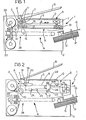
- a copying machine Shown in the drawings is a copying machine, generally indicated 1, which is intended to allow the reproduction in colour of an image (original) 0 carried on a sheet of paper or the like.
- the reproduction is produced on printable substrates constituted by sheets of paper P contained in a cassette C that is attached, usually in a removable manner, to the structural housing of the machine 1, this housing being generally indicated 2.
- a transparent glass plate 5 is illustrated on which the original 0 is located and held firm by means of an ordinary pivotably raisable blanket 6.
- reference 7 indicates a carriage which is movable on guides 8 carried by the housing 2 of the machine 1 in positions facing the glass 5 on which the original 0 is located.
- the carriage 7 is driven by means of a belt transmission generally indicated 9 controlled by a drive pulley 10 rotated by a motor (not visible) preferably of the d.c. or stepping type.
- a scanning movement longitudinally of the transparent glass 5 may thus be imparted to the carriage 7.
- the carriage 7 is brought from an initial starting position, represented in full outline and indicated A in Figure 1, to an end of stroke position indicated in broken outline by B in the same Figure.
- Two lamps 11 are mounted on the carriage 7 for illuminating the original 0 during the scanning movement.
- the lamps 11 emit light with a spectrum which extends over the entire visible range.
- Reference 12 indicates an objective preferably constituted by an array of optical fibres,that is intended to effect the scanning of the original 0 illuminated by the lamps 11.
- the radiation reflected from the elementary area of the original 0 framed by the objective 12 is projected on to a photo-detector 13 after it has passed through one of three chromatic filters 14, 15 and 16 so as to eliminate the blue component, the green component and the red component of the reflected radiation respectively.
- the filters 14, 15 and 16 can be interposed selectively in the path of the radiation from the objective 12 to the photo-detector 13 by the operation of a small d.c. or stepping motor 17 mounted on the carriage 7.
- the colours of the chromatic filters 14, 15 and 16 correspond to the primary colours of a colour triangle.
- the intensity of the radiation incident on the photo-detector 13 is indicative of the chromatic components of the reflected radiation complementary to that of the filter.
- the intensity of the radiation incident on the photo-detector 13 when the filter 14 (blue) is interposed between the objective 12 and the photo-detector 13 is indicative of the yellow content of the elementary area being scanned at that instant.
- the intensity of the radiation incident on the photo-detector 13 is indicative of the magenta content of the elementary area of the original 0 being scanned at that instant while the cyan content of that elementary area is determined by aligning the filter 17 (red) with the objective 12.
- the photo-detector 13 is normally constituted by a semi-conductor photo-detector such as, for example, an amorphous silicon sensor.
- a semi-conductor photo-detector such as, for example, an amorphous silicon sensor.
- One of the alternatives possible for the photo-detector 13, is to use an optical CCD sensor (Charge Coupled Device). It is thus possible to use a photo-detector comprising a linear array of photosensitive elements arranged to examine simultaneously elementary areas defining an elementary line of the original 0.
- FIG. 2 Another configuration which permits an analysis of the chromatic characteristics of the original 0 is illustrated in Figure 2 in which three light sources 18, 19 and 20 are mounted on the carriage 7 movable on the guides 8, each light source having a narrow band emission spectrum concentrated around a wavelength corresponding to one of the primary colours.
- the source 18 may be constituted by an array of light emitting diodes (LED) having an emission spectrum concentrated about the wavelength corresponding to blue while the source 19 is constituted by an array of light emitting diodes with an emission spectrum concentrated about the wavelength corresponding to green, and the source 20 is constituted by an array of light emitting diodes having an emission spectrum concentrated about the wavelength corresponding to red.
- LED light emitting diodes
- 21 and 23 are shown three mirrors for capturing the radiation reflected from the surface of the original 0 when the original itself is illuminated, for example as shown in Figure 2, with one of the light sources 18, 19 and 20,and for directing this reflected radiation to a photo-detector 24 which is fixed to the housing 2 of the copying machine and is provided with a focussing objective 25.
- the reflecting mirror 21 is mounted on the carriage 7 at an inclination of about 45° to the plane of the transparent glass 5.
- the radiation reflected from the original 0 is thus directed parallel to the plane of the glass 5 from the mirror 21 towards the mirror 22 which in its turn reflects the radiation perpendicular to the glass 5 and away from the glass itself.
- the radiation transmitted by the mirror 22 is finally reflected by the mirror 23 which reconfers on the radiation a direction of propogation parallel to the glass 5 so that the path of propogation of the radiation between the mirror 21 and the photo-detector 24 is approximately U-shaped.
- the mirrors 22 and 23 are mounted on further carriage 26 movable on the guides 8.
- the carriage 26 is driven by an auxiliary section of the belt transmission 9 at a speed equal to half the translational speed of the carriage 7 carrying the mirror 21.
- the length of the optical path between the original 0 and the photo-detector 24 is maintained constant.
- the system constituted by the carriage 7 carrying the sources - 18, 19, 20 and the mirror 21 and the carriage 26 carrying the mirrors 22 and 23 is thus able to effect, together with the photodetector 24, a scanning of the original 0 substantially similar to that achieved by using the configuration of photosensor means described with reference to Figure 1.
- the starting position of the scanning movement is illustrated in full outline and indicated A while the end of stroke position is illustrated in broken outline and indicated B.
- the movement of the belt transmission 9 which drives the carriages 7 and 26 is controlled by a d.c. or stepping motor (not shown) having different rotational speeds in its two senses of rotation whereby to effect gradual scanning of the original 0 during movement from position A towards position B and a rapid return movement.
- the illumination of the original 0 by the light source 18 allows the photo-detector 24 to output a signal indicative of the yellow content of the original.
- illumination of the original 0 with the source 19 (green) or with the source 20 (red) makes it possible to obtain, at the output of the photo- detector 24, signals indicative of the magenta content and the cyan content of the original respectively.
- the scanning of the original 0 is carried out in lines, using linear arrays of light emitting diodes (LED) as the light sources 18, 19 and 20, each of the diodes having a longitudinal extent equal to the length of an elementary line of the original 0.
- a CCD Photo-detector which can examine all the elementary areas defining one of the elementary lines of the original 0 can usefully be employed as the photo-detector 24.
- this portion which is indicated 4
- this portion has characteristics which are substantially identical in the machine of Figure 1 and in the machine of Figure 2)
- a printing device and a device for feeding the sheets P, these devices being generally indicated 27 and 28 respectively.
- the feed device 28 is illustrated in detail in Figure 3.
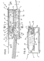
- the printing device 27 is constituted by a ribbon-using electric thermal printer.
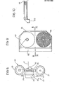
- the printer 27 is supplied with a thermal print ribbon 29 which is wound, as illustrated in greater detail in Figure 5, between a supply spool 30 and a take-up spool 31.
- the spools 30 and 31 are mounted within a container (cassette or cartridge) 32 which ensures the correct positioning of the ribbon 29, facilitating its loading and replacement.
- the ribbon 29, which is a thermal print ribbon, carries a deposited layer of heat meltable ink arranged in an ordered succession of frames of different colours.
- the colours of these frames is selected so as to render the reproduction of the original 0 on the sheets P possible by subtractive mixing.
- Reference 33 indicates a printing head arranged to act on the ribbon 29 to transfer to the sheets P, dot configurations (digital patterns) the chromatic contents of which are defined on the basis of the information derived during scanning of the original 0 carried out in the manner described above with reference to Figures 1 and 2.
- printing of the yellow component of the reproduced image uses the information derived when the filter 14 (blue) is interposed between the objective 12 and the photo-detector 13, or the information derived when the original is illuminated with the photo-diode array 18 (blue).
- printing of the magenta component uses the information derived during scanning of the original 0 with the interposition of the filter 15 (green) between the objective 12 and the photo-detector 13, or the information derived when the original 0 is illuminated with the light emitting diode array 19 (green).
- printing of the cyan component uses the information derived during scanning of the original 0 with the filter 16 (red) interposed between the objective 12 and the photo-detector 13, or the information derived during scanning of the original 0 when the latter is illuminated with the light emitting diode array 20 (red).
- the number of coloured dots in each of the "digital patterns" is inversely proportional to the exposure undergone by the photo- detector 13 or the photo-detector 24 during the corresponding scanning phase.
- a black and white printing operation can be carried out together with the three chromatic printing phases in order to enrich the trichromatic print, particularly with regard to its definition.
- the printing head 33 is mounted on a support 34 fixed to the housing 2 of the copying machine 1.
- a roller 35 is arranged to feed the sheet P being used as the reproduction substrate and the ribbon 29 past the printing head 33 in such a disposition that the ribbon is sandwiched between the head 33 and the sheet P.
- the transverse dimensions of the ribbon 29 and the corresponding longitudinal dimension of the printing head 33 can be selected so as to allow one printing phase to be carried out simultaneously on all the elementary areas defining an elementary line of the sheet P, that is, in correspondence with the configuration of the photo-detector 13 or the photo- detector 24. (Parallel reproduction system).
- a printing head 33 arranged to act simultaneously on elementary areas defining a fraction of an elementary line of the sheet P used for the printing of the reproduced image.
- the printing head 33 and its supports are mounted on a carriage movable transverse the direction of scanning of the original 0 (Parallel-series reproduction system).
- the arrangement described makes it possible to effect, simultaneously or nearly simultaneously, both the detection of one of the chromatic characteristics of an elementary line of the original 0 and the printing of the corresponding chromatic component of a line of the image reproduced on one of the sheets P.
- the trichromatic reproduction (possibly with the addition of a black and white component) of an elementary line of the original C is thus achieved by means of three (four in the case of the addition of black and white) successive operations of scanning the original and three (four in the case of the addition of black and white) operations of printing on one of the sheets P.
- reference 36 indicates a motor-driven roller(sheet take-up roller) which is intended to allow the sequential take up of the sheets P from the cassette C.
- each of the sheets is caused to slide beneath three drive rollers 37 against each of which a lower counter-roller 38 acts.
- the rollers 37, 38 advance each sheet until the margin of the sheet is brought into alignment with a photoelectric sensor (photocell) 39 located close to the roller 35.
- the sheet P is disengaged from the roller-counter roller pair 37, 38 furthest from the roller 35 and rests on the other two counter rollers 38, each of which is mounted at the end of one of the arms of an L-shaped bracket 40 that can be pivoted under the action of a corresponding relay 41.
- the arrangement is such that once the front edge of the sheet P has been aligned with the photodetector 39, the brackets 40 are oriented so as to remove the corresponding counter.rollers 38 from the overlying rollers 37.
- Reference 42 indicates a roller the axis of rotation of which is coplanar with and perpendicular to the axis of rotation of the rollers 37.
- the roller 42 is mounted in a position substantially corresponding to one of the side margins of the sheet P introduced into the feed device 28.
- roller 42 Beneath the roller 42 is a counter roller 43 which is also supported by one of the arms of a pivoted bracket 44 that can be oriented by means of a relay 45.
- the relay 45 controls the raising of the counter roller 43 against the roller 42 immediately the counter rollers 38 mounted on the brackets 40 have been lowered to allow the sheet P to move freely over the rollers 38 themselves.
- roller 42 and the counter roller 41 are clamped on the sheet P.
- Rotation of the roller 42 about its axis thus causes transverse movement of the sheet - P and pushes the sheet itself against a side reference (register) 46 ( Figure 4) located in. a predetermined fixed position which can be selectively set in dependence on the dimensions of the sheet P.
- the reference 46 is positioned by an electromagnet (not shown) operated before the clamping of the roller-counter roller pair 42, 43.
- the reference 46 is positioned along a path directed towards the interior of the feed device 28 so as to ensure correct alignment of the sheet P even when, during introduction into the feed device, the margin of the sheet P adjacent the roller-counter roller pair 42, 43 is displaced irregularly towards the exterior of the machine 1.
- roller 42 and the roller 37 adjacent the roller 35 are rotated by a single motor 47 through two selectively-engageable transmissions.
- the arrangement is such that, once the sheet P has been aligned with the reference 46 by means of the roller 42, the motor 47 is coupled to the roller 37 and starts to advance the sheet towards the printing device 27.
- the roller 35 Immediately the front edge of the sheet P passes in front of the photodetector 48 the roller 35 is caused to rotate. The roller 35 draws the sheet P (and the ribbon 29) against the printing head 33 with an advancing motion which emulates the movement of the carriage 7 relative to the original 0 located on the transparent glass.
- the photosensor elements mounted on the carriage 7 scan lines of the original 0.
- the roller 35 feeds the sheet P to the printing head 33 with a gradual advancing motion in which each step corresponds to the presentation of an elementary line of the sheet P to the printing head 33.
- the printing head 33 is arranged to act simultaneously on the entire line (reproduction in parallel) or comprises a printing element which is movable parallel to the axis of the roller 35 so as to achieve printing operations sequentially on adjacent regions of one line (parallel-series reproduction).
- the operating arrangement described is thus such that the photosensor elements mounted on the carriage 7 and the printing device 27 act simultaneously on corresponding regions of the original 0 and of the sheet P used as the reproduction substrate.
- the sheet P continues in its path of movement within the device 28, sliding over the rollers 37 against which the sheet itself is pressed by a further series of counter rollers indicated 49.
- this guide device 50 In its first operating position, this guide device 50 directs the sheet P beneath the rollers 37 again.
- the guide device 50 guides the sheet P which is located above the rollers 37 towards a pair of expulsion rollers 52 which transfer the sheet itself to a collecting cassette G located above the feed cassette C.
- the guide device is positioned so as to cause the same sheet P to be circulated around the feed device 28 for a number of times equal to the number of successive monochromatic printing operations necessary to obtain the final desired product.
- this number is three whenever three successive printing operations are to be effected, corresponding to the transfer onto the sheet P of the yellow, magenta and cyan components of the original 0 or four whenever the three printing operations indicated above are to be followed by a further operation for enriching the image reproduced,by means of a black and white printing phase.
- the guide device 50 will cause the sheet P to be transferred to the collecting cassette G after a single passage of the sheet P past the printing device 27.
- the unidirectional circulation of the sheet P through the feed device 28 means that the head 33 and the ribbon 29 do not have to be moved away from the printing roller 35 and this further increases the precision of the print.
- a single motor (not illustrated) is used for driving the printing roller 35 and the transmission 9 which drives the carriage 7.
- the printing head 33 is of the "full parallel" type, being a thin film or thick film version with integral driver.
- This head 33 is mounted on the support 34 with the inter-position of a resilient element 33a which.ensures that a certain uniformly-distributed pressure is exerted between the head 33 and the printing roller 35; which is normally made of rubber.
- the support 34 can be oriented about an axis parallel the the axis of the printing roller 35 so as to allow the manual disengagement of the head 33 from the roller 35 to enable the replacement or renewal of the cartridge 32 containing the ribbon 29.
- the housing 2 of the machine 1 has an upper pair of guides along which a carriage 53 is movable, the original 0 being laid carefully on the carriage and held firm by a raisable blanket substantially identical to that indicated 6 in Figures 1 and 2.
- the carriage 53 is movable in a longitudinal direction relative to the housing 2 between two end positions one of which (starting position) is illustrated in full outline and indicated S in Figure 6 and the other of which (end of stroke position) is illustrated in broken outline and indicated T in the same drawing.
- the cassette C for feeding the sheets P and the cassette G for collecting the reproductions are aligned, on opposite sides of the housing 2 in the longitudinal direction of movement of the carriage 53.
- Two parallel cylindrical guides 54 and 55 are located within the housing 2 and extend in directions perpendicular to the direction of sliding of the carriage 53.
- a further carriage 56 is movable on the guides 54 and 55 and carries a system for examining the original 0 of the type described with reference to the embodiments illustrated in Figure 1 or Figure 2.
- FIGS 6 and 7 schematically show the arrangement on the carriage 56 of a pair of broad spectrum light sources 57, an objective 58 and a bank of three chromatic filters 59, 60 and 61 acting at wavelengths respectively corresponding approximately to blue, green and red.
- the filters 59, 60 and 61 can be interposed selectively between the objective 58 and a photodetector 62, for example an amorphous silicon photodetector, arranged to generate electrical signals indicative of the intensity of the radiation incident thereon.
- the displacement of the filters 59, 60 and 61 is effected by a motor 63 mounted on the carriage 56.
- the lamps 57 are intended to illuminate the original 0 so as to generate reflected radiation which is captured by the objective 58.
- the objective 58 transmits this reflected radiation to the photodetector 62 through one of the filters 59, 60, 61 selected by operation of the motor 63.
- the intensity of the radiation incident on the photodetector 62 when the blue filter 59 is associated with the objective 58 is indicative of the yellow content of the elementary area of the original 0 being scanned, at that moment, while the magenta and cyan chromatic components of the same elementary area are detected by associating the green filter 60 or red filter 61 respectively, with the objective 58.
- the original 0 is located on a transparent plate 5 which is fixed relative to the housing 2 while in the embodiment of Figure 7, the carriage 53, which is also provided underneath with a transparent surface (thus making possible the scanning of the original 0 by the photosensor devices mounted on the carriage 56), is movable longitudinally relative to the housing 2.
- Reference 64 indicates a thermal printing head supported on a carriage entrained by the carriage 56 in its back and forth movement along the guides 54 and 55.
- a feed device generally indicated 65 is arranged to take up sheets P from the cassette C and transfer these sheets longitudinally of the housing 2 towards the collecting cassette G which, as indicated above, is located on the opposite side of the housing 2.
- Reference 66 indicates a container (cassette or cartridge) within which are two spools 67, 68 acting respectively as the feed spool and take-up spool for a print ribbon 69 substantially identical to the ribbon 29 of the container.32.
- the loaded position of the container 66 within the housing 2 is such that the axes of the spools 67 and 68 lie in a plane perpendicular to the plane of sliding of the carriage 53 carrying the original.
- the container 66 is shaped so that a portion of the ribbon 69 (active portion), of a length substantially corresponding to the working stroke of the carriage 56, lies in a plane parallel to the plane in which the original 0 is located on the carriage 53.
- this active portion of the ribbon is located between the printing head 64 supported by the carriage 56 and the plane of sliding of the sheets P in the feed device 65.
- the head 64 which is mounted on the carriage 56 by means of a pivotal bracket 70 operated by a relay 71, is thus able to press the active portion of the ribbon 69 against the sheet P supplied by the feed device 65.
- the pressure exerted by the head 64 is opposed by a resiliently yieldable support 72 which extends over the entire region in which the head operates.
- the feed device 65 includes a sheet take-up roller 73, three drive rollers 74, two of which extend along the sides of the support element 72, and a pair of expulsion rollers 75.
- rollers 74 lie beneath corresponding counter rollers 76 and are rotated via a gear wheel and worm screw coupling from a drive pulley 77 which is, in turn, connected, for example through a belt transmission, to the drive mechanism of the carriage 53 on which the original 0 is mounted.
- each of the sheets P taken from the cassette C is advanced beneath the active portion of the ribbon 69 on which the printing head 64 acts, at a speed of advance corresponding to the speed of movement of the carriage 53.
- the trichromatic reproduction of the original 0 on the sheets P requires three successive scanning operations, for detecting the three primary chromatic components of the original and three successive printing operations for reproducing the chromatic components on the sheet P.
- the number of scanning and printing operations rises to four whenever it is desired to enrich the trichromatic reproduction with a black and white print.
- the operations of scanning and printing one chromatic component are carried out over the entire surface of the original 0 and over the entire surface of the sheet P before passing on to the operations of scanning and printing a different chromatic component. This makes it necessary to recirculate a single sheet P previously output.
- the reproduction of the original is carried out by scanning three (four, in the case of enrichment with black and white) times across each line of the original and effecting simultaneously with each scanning of the original 0, the printing of the appropriate chromatic component for the corresponding line on the sheet P.
- the scanning movement of the original by the objective 58 and the scanning movement of the sheet P by the head 64 are thus strictly synchronised since both the objective 58 and the printing head 64 are supported by the carriage 56.
- the movement of the carriage 56 is effected by means of a belt transmission 79 ( Figure 7) driven by a motor, for example a d.c. or stepping motor, that has a different rotational speed in its two senses of rotation whereby to permit rapid return of the carriage 56 from its end of stroke position V to its starting position U at the end of each scanning and printing stroke.
- the printing head 64 draws with it a roller 80 for detaching the ribbon 69 from the sheet P so that the advancement of the ribbon 69 and the longitudinal advance of the sheet P are not hindered.
- the thermal print ribbon 69 carries,a deposit of heat meltable ink arranged in an ordered succession of consecutive frames of different colours, each frame having a length equal to the transverse extent of the sheet P.
- the printing head 64 is raised from the ribbon 69 by operation of the relay 71 between two successive scans so as not to obstruct the sliding of the ribbon itself and change over between two differently-coloured frames.
- Raising of the printing head 64 and its withdrawal from the ribbon 69 is also effected during the removal of the container 66 from the machine in order to allow the replacement of the ribbon.
- the invention allows colour copying machines to be made which are very reliable and can ensure considerable consistency of results with time without adjustment.
- the use of a digital printing system allows machines embodying the invention to have different functions added, such as for example, printing or remote transmission of images.
- the reproduction portion 4 may then be connected remotely to the scanning portion 3 of a similar machine at a remote location so as to act as a telecopier.
- reproduction portion 4 it is also possible to connect the reproduction portion 4 to any other source of numerical data relating to an image, such as an electronic processor, or to a disc or tape on which is stored, after a possible intermediate processing operation, data collected by a photosensor during scanning of the image to be reproduced.
- any other source of numerical data relating to an image such as an electronic processor, or to a disc or tape on which is stored, after a possible intermediate processing operation, data collected by a photosensor during scanning of the image to be reproduced.
- the apparatus of the invention is thus operated as a colour printer.
Abstract
Description
- The present invention relates to methods of reproducing coloured images and, in particular,to a method of reproducing a coloured image on a printable substrate.
- The method of the invention is characterised in that it comprises the steps of:
- - providing polychromatic photosensor means arranged to scan the said coloured image in order to produce, for each elementary area scanned,signals indicative of the chromatic components of the elementary area itself,
- - providing polychromatic printing means connected to the photosensor means in order to impart to a substrate chromatic characteristics corresponding to the signals produced by the photosensor means, and
- - producing, during repeated scanning operations, a movement of the photosensor means relative to the coloured image and a simultaneous movement of the printing means relative to the substrate; the relative movements being coordinated with each other such that the photosensor means and the printing means act simultaneously on corresponding regions of the coloured image and of the substrate; each of the scanning operations resulting in the detection of one of the chromatic components of the image and the reproduction of this component on the substrate.
- A further object of the present invention is to provide apparatus for reproducing a coloured image on a printable substrate, the apparatus being characterised in that it comprises:
- - a structural housing having means for locating the image in a predetermined position,
- -polychromatic photosensor means arranged to scan the coloured image in order to produce, for each elementary area scanned, signals indicative of the chromatic characteristics of the elementary area itself,
- - polychromatic printing means fed with the signals produced by the photosensor means,
- - a device for feeding printable substrates to the printing means, and
- - drive means acting on the photosensor means and on the device for feeding substrates in order to produce, for each substrate and for repeated scanning operations, each of which results in the detection of one of the chromatic components of the image and the reproduction of this component on the substrate, a relative movement of the photosensor means and the image and a simultaneous and coordinated relative movement of the printing means and the substrate, whereby the photosensor means and the printing means act simultaneously on corresponding regions of the image and of the substrate; means also being provided for ensuring, at the beginning of each of the scanning operations, identical positioning of the substrate relative to the printing means.
- The invention enables the reproduction of coloured images using intrinsically reliable modules whereby to ensure substantial consistency in results over a period of time without regulating adjustments, with smaller dimensions, weight and costs than solutions at present used in the art of xerography. More particularly, the invention allows digital electronic copiers to be made for which it is relatively simple to provide additional different functions such as printing, remote transmission of images and the like.
- The invention will now be described, purely by way of non-limiting example, with reference to the appended drawings, in which:
- Figure 1 is a vertical median section illustrating schematically the internal structure of apparatus embodying the invention,
- Figure 2 is a view substantially identical to Figure 1 illustrating a first variant of the apparatus embodying the invention,
- Figure 3 is a further sectional view illustrating commom elements of the apparatus of Figure 1 and
- Figure 2 in greater detail,
- Figure 4 is a schematic plan view substantially corresponding to Figure 3,
- Figure 5 is a side view of one of the elements illustrated in Figures 1 to 3 on an enlarged-scale,
- Figure 6 is a vertical median section illustrating schematically the structure of another apparatus embodying the invention,
- Figure 7 is a schematic view approximately corresponding to line VII-VII of Figure 6,
- Figure 8 is a schematic sectional view approximately corresponding to line VIII-VIII of Figure 6,
- Figure 9 is a median sectional view of one of the elements seen in Figures 6 and 7, and
- Figure 10 is a section taken on line X-X of Figure 9.
- The description which follows illustrates the application of the invention to a paper copying machine using an electric thermal printing device.
- However, in the claims below, the term "printable substrate" is intended to identify any paper, celluloid, plastics or like substrate to which a visually-perceptible graphical indication may be transferred by corresponding "printing means". Similarly, the term "image" indicates generically the original to be reproduced, regardless of the form in which this original is present (print on paper, plastics material, celluloid etc.).
- Shown in the drawings is a copying machine, generally indicated 1, which is intended to allow the reproduction in colour of an image (original) 0 carried on a sheet of paper or the like. The reproduction is produced on printable substrates constituted by sheets of paper P contained in a cassette C that is attached, usually in a removable manner, to the structural housing of the
machine 1, this housing being generally indicated 2. - In all the copying machines illustrated in the drawings, it is possible to distinguish a first portion generally indicated 3, in which the detection of the characteristics of the original image 0 is effected, and a second portion, generally indicated 4, in which the image 0 is reproduced on one of the sheets P using the information on the characteristics derived in the
first portion 3. - With reference to the embodiments illustrated in Figures 1 to 3, a
transparent glass plate 5 is illustrated on which the original 0 is located and held firm by means of an ordinary pivotably raisable blanket 6. - In Figure 1
reference 7 indicates a carriage which is movable onguides 8 carried by thehousing 2 of themachine 1 in positions facing theglass 5 on which the original 0 is located. - The
carriage 7 is driven by means of a belt transmission generally indicated 9 controlled by adrive pulley 10 rotated by a motor (not visible) preferably of the d.c. or stepping type. - A scanning movement longitudinally of the
transparent glass 5 may thus be imparted to thecarriage 7. As a result of this movement, thecarriage 7 is brought from an initial starting position, represented in full outline and indicated A in Figure 1, to an end of stroke position indicated in broken outline by B in the same Figure. - Return of the
carriage 7 from the end of stroke position B to its starting position A is effected by reversing the sense of rotation of the motor driving thepulley 10, the motor preferably being made to operate at a higher speed than that used during scanning of the original 0 from position A towards position B. - Two
lamps 11 are mounted on thecarriage 7 for illuminating the original 0 during the scanning movement. - The
lamps 11 emit light with a spectrum which extends over the entire visible range. -
Reference 12 indicates an objective preferably constituted by an array of optical fibres,that is intended to effect the scanning of the original 0 illuminated by thelamps 11. The radiation reflected from the elementary area of the original 0 framed by the objective 12 is projected on to a photo-detector 13 after it has passed through one of threechromatic filters - The
filters detector 13 by the operation of a small d.c. or steppingmotor 17 mounted on thecarriage 7. - The colours of the
chromatic filters detector 13 is indicative of the chromatic components of the reflected radiation complementary to that of the filter. - Thus, the intensity of the radiation incident on the photo-
detector 13 when the filter 14 (blue) is interposed between the objective 12 and the photo-detector 13 is indicative of the yellow content of the elementary area being scanned at that instant. - When the
motor 17 brings the filter 15 (green) into alignment with the objective 12, the intensity of the radiation incident on the photo-detector 13 is indicative of the magenta content of the elementary area of the original 0 being scanned at that instant while the cyan content of that elementary area is determined by aligning the filter 17 (red) with the objective 12. - The photo-
detector 13 is normally constituted by a semi-conductor photo-detector such as, for example, an amorphous silicon sensor. One of the alternatives possible for the photo-detector 13, is to use an optical CCD sensor (Charge Coupled Device). It is thus possible to use a photo-detector comprising a linear array of photosensitive elements arranged to examine simultaneously elementary areas defining an elementary line of the original 0. - Another configuration which permits an analysis of the chromatic characteristics of the original 0 is illustrated in Figure 2 in which three
light sources carriage 7 movable on theguides 8, each light source having a narrow band emission spectrum concentrated around a wavelength corresponding to one of the primary colours. For example, thesource 18 may be constituted by an array of light emitting diodes (LED) having an emission spectrum concentrated about the wavelength corresponding to blue while thesource 19 is constituted by an array of light emitting diodes with an emission spectrum concentrated about the wavelength corresponding to green, and thesource 20 is constituted by an array of light emitting diodes having an emission spectrum concentrated about the wavelength corresponding to red. - By 21, 22 and 23 are shown three mirrors for capturing the radiation reflected from the surface of the original 0 when the original itself is illuminated, for example as shown in Figure 2, with one of the
light sources detector 24 which is fixed to thehousing 2 of the copying machine and is provided with a focussingobjective 25. - The reflecting
mirror 21 is mounted on thecarriage 7 at an inclination of about 45° to the plane of thetransparent glass 5. the radiation reflected from the original 0 is thus directed parallel to the plane of theglass 5 from themirror 21 towards themirror 22 which in its turn reflects the radiation perpendicular to theglass 5 and away from the glass itself. The radiation transmitted by themirror 22 is finally reflected by themirror 23 which reconfers on the radiation a direction of propogation parallel to theglass 5 so that the path of propogation of the radiation between themirror 21 and the photo-detector 24 is approximately U-shaped. - The
mirrors further carriage 26 movable on theguides 8. Thecarriage 26 is driven by an auxiliary section of the belt transmission 9 at a speed equal to half the translational speed of thecarriage 7 carrying themirror 21. Thus the length of the optical path between the original 0 and the photo-detector 24 is maintained constant. - The system constituted by the
carriage 7 carrying the sources - 18, 19, 20 and themirror 21 and thecarriage 26 carrying themirrors photodetector 24, a scanning of the original 0 substantially similar to that achieved by using the configuration of photosensor means described with reference to Figure 1. - Again in this case, the starting position of the scanning movement is illustrated in full outline and indicated A while the end of stroke position is illustrated in broken outline and indicated B.
- The movement of the belt transmission 9 which drives the
carriages - In a substantially similar manner to the trichromatic analysis technique described with reference to the embodiment of Figure 1, the illumination of the original 0 by the light source 18 (blue) allows the photo-
detector 24 to output a signal indicative of the yellow content of the original. However, illumination of the original 0 with the source 19 (green) or with the source 20 (red) makes it possible to obtain, at the output of the photo-detector 24, signals indicative of the magenta content and the cyan content of the original respectively. - Again in this case, the scanning of the original 0 is carried out in lines, using linear arrays of light emitting diodes (LED) as the
light sources detector 24. - From what has been described above, it is thus clear that the trichromatic analysis system using three restricted-
spectrum sources lamps 11 and thefilters - In the portion of the copying
machine 1 arranged to reproduce the image onto the sheets P(this portion, which is indicated 4, has characteristics which are substantially identical in the machine of Figure 1 and in the machine of Figure 2), there can be distinguished a printing device and a device for feeding the sheets P, these devices being generally indicated 27 and 28 respectively. Thefeed device 28 is illustrated in detail in Figure 3. - In the embodiment illustrated, the
printing device 27 is constituted by a ribbon-using electric thermal printer. - The
printer 27 is supplied with athermal print ribbon 29 which is wound, as illustrated in greater detail in Figure 5, between asupply spool 30 and a take-upspool 31. - The
spools ribbon 29, facilitating its loading and replacement. - The
ribbon 29, which is a thermal print ribbon, carries a deposited layer of heat meltable ink arranged in an ordered succession of frames of different colours. - The colours of these frames, each of which has an extent corresponding to the size of the substrate, is selected so as to render the reproduction of the original 0 on the sheets P possible by subtractive mixing.
- With reference to the chromatic characteristics of the
filters sources -
Reference 33 indicates a printing head arranged to act on theribbon 29 to transfer to the sheets P, dot configurations (digital patterns) the chromatic contents of which are defined on the basis of the information derived during scanning of the original 0 carried out in the manner described above with reference to Figures 1 and 2. - More particularly, printing of the yellow component of the reproduced image uses the information derived when the filter 14 (blue) is interposed between the objective 12 and the photo-
detector 13, or the information derived when the original is illuminated with the photo-diode array 18 (blue). - Similarly, printing of the magenta component uses the information derived during scanning of the original 0 with the interposition of the filter 15 (green) between the objective 12 and the photo-
detector 13, or the information derived when the original 0 is illuminated with the light emitting diode array 19 (green). - Finally, printing of the cyan component uses the information derived during scanning of the original 0 with the filter 16 (red) interposed between the objective 12 and the photo-
detector 13, or the information derived during scanning of the original 0 when the latter is illuminated with the light emitting diode array 20 (red). - To reproduce each elementary area of the image it is thus necessary to effect three successive scannings - respectively carried out with the filter 14 or the ligbt-emitting
diode array 18, thefilter 15 or the light-emitting diode array 19 (green) and thefilter 16 for the light-emitting diode array 20 (red), and three successive printing operations, using adjacent frames of theribbon 29 having respectively yellow, magenta and cyan colours. - During each printing operation, the number of coloured dots in each of the "digital patterns" is inversely proportional to the exposure undergone by the photo-
detector 13 or the photo-detector 24 during the corresponding scanning phase. - In order to achieve a good colour rendering, it is necessary for the resolution to be adequate and for the printed pattern to be constituted by a sufficient number of elementary dots disposed, for example, in a 3 x 3 or 4 x 4 square matrix.
- In known manner (for example, by arranging for the
motor 17 to have an operating position in which none of thefilters detector 13, or by arranging for the light emittingdiode sources detector 13 or the photo-detector 24 information relating solely to the brightness of the original and to use aribbon 29 including black or grey colour frames. In this manner it is possible to make the copying machine operate in black and white whenever necessary. - A black and white printing operation can be carried out together with the three chromatic printing phases in order to enrich the trichromatic print, particularly with regard to its definition.
- As is best seen in Figure 5, the
printing head 33 is mounted on asupport 34 fixed to thehousing 2 of the copyingmachine 1. - A
roller 35 is arranged to feed the sheet P being used as the reproduction substrate and theribbon 29 past theprinting head 33 in such a disposition that the ribbon is sandwiched between thehead 33 and the sheet P. - The transverse dimensions of the
ribbon 29 and the corresponding longitudinal dimension of theprinting head 33 can be selected so as to allow one printing phase to be carried out simultaneously on all the elementary areas defining an elementary line of the sheet P, that is, in correspondence with the configuration of the photo-detector 13 or the photo-detector 24. (Parallel reproduction system). - Alternatively, it is possible to use a
printing head 33 arranged to act simultaneously on elementary areas defining a fraction of an elementary line of the sheet P used for the printing of the reproduced image. - In this case, the
printing head 33 and its supportsare mounted on a carriage movable transverse the direction of scanning of the original 0 (Parallel-series reproduction system). - In each case the arrangement described makes it possible to effect, simultaneously or nearly simultaneously, both the detection of one of the chromatic characteristics of an elementary line of the original 0 and the printing of the corresponding chromatic component of a line of the image reproduced on one of the sheets P.
- The trichromatic reproduction (possibly with the addition of a black and white component) of an elementary line of the original C is thus achieved by means of three (four in the case of the addition of black and white) successive operations of scanning the original and three (four in the case of the addition of black and white) operations of printing on one of the sheets P.
- Thus for this purpose it is necessary to feed each of the sheets P to the
printing device 27 three (or four) times consecutively while ensuring that the positions taken up by the sheet P are the same during successive printing phases so as to avoid blurring and similar phenomena of degradation of the image reproduced. - This result is achieved with the feed device for the sheets P illustrated in detail in Figures 3 and 4.
- In these Figures reference 36 indicates a motor-driven roller(sheet take-up roller) which is intended to allow the sequential take up of the sheets P from the cassette C.
- Under the action of the sheet take-up
roller 36, each of the sheets is caused to slide beneath threedrive rollers 37 against each of which alower counter-roller 38 acts. Therollers roller 35. - Under these conditions, the sheet P is disengaged from the roller-
counter roller pair roller 35 and rests on the other twocounter rollers 38, each of which is mounted at the end of one of the arms of an L-shapedbracket 40 that can be pivoted under the action of acorresponding relay 41. - The arrangement is such that once the front edge of the sheet P has been aligned with the
photodetector 39, thebrackets 40 are oriented so as to remove thecorresponding counter.rollers 38 from the overlyingrollers 37. - Reference 42 (see also Figure 4) indicates a roller the axis of rotation of which is coplanar with and perpendicular to the axis of rotation of the
rollers 37. - As seen in Figure 4, the
roller 42 is mounted in a position substantially corresponding to one of the side margins of the sheet P introduced into thefeed device 28. - Beneath the
roller 42 is acounter roller 43 which is also supported by one of the arms of a pivotedbracket 44 that can be oriented by means of arelay 45. - The
relay 45 controls the raising of thecounter roller 43 against theroller 42 immediately thecounter rollers 38 mounted on thebrackets 40 have been lowered to allow the sheet P to move freely over therollers 38 themselves. - Under these conditions, the
roller 42 and thecounter roller 41 are clamped on the sheet P. Rotation of theroller 42 about its axis thus causes transverse movement of the sheet-P and pushes the sheet itself against a side reference (register) 46 (Figure 4) located in. a predetermined fixed position which can be selectively set in dependence on the dimensions of the sheet P. - Normally the
reference 46 is positioned by an electromagnet (not shown) operated before the clamping of the roller-counter roller pair - The
reference 46 is positioned along a path directed towards the interior of thefeed device 28 so as to ensure correct alignment of the sheet P even when, during introduction into the feed device, the margin of the sheet P adjacent the roller-counter roller pair machine 1. - As is seen in Figure 4, the
roller 42 and theroller 37 adjacent theroller 35 are rotated by asingle motor 47 through two selectively-engageable transmissions. - The arrangement is such that, once the sheet P has been aligned with the
reference 46 by means of theroller 42, themotor 47 is coupled to theroller 37 and starts to advance the sheet towards theprinting device 27. - Downstream of the
photodetector 39, in the direction of movement of the sheet P towards the printing device, there is a further photodetector (photocell) 48. - Immediately the front edge of the sheet P passes in front of the
photodetector 48 theroller 35 is caused to rotate. Theroller 35 draws the sheet P (and the ribbon 29) against theprinting head 33 with an advancing motion which emulates the movement of thecarriage 7 relative to the original 0 located on the transparent glass. - In the embodiment illustrated in Figures 1 and 2, the photosensor elements mounted on the
carriage 7 scan lines of the original 0. In this case, theroller 35 feeds the sheet P to theprinting head 33 with a gradual advancing motion in which each step corresponds to the presentation of an elementary line of the sheet P to theprinting head 33. As indicated above, theprinting head 33 is arranged to act simultaneously on the entire line (reproduction in parallel) or comprises a printing element which is movable parallel to the axis of theroller 35 so as to achieve printing operations sequentially on adjacent regions of one line (parallel-series reproduction). - The operating arrangement described is thus such that the photosensor elements mounted on the
carriage 7 and theprinting device 27 act simultaneously on corresponding regions of the original 0 and of the sheet P used as the reproduction substrate. - As a result of its gradual advance between the
roller 35 and theprinting head 33, the sheet P continues in its path of movement within thedevice 28, sliding over therollers 37 against which the sheet itself is pressed by a further series of counter rollers indicated 49. - Adjacent the
counter roller 49 overlying theroller 37 that occupies the position furthest from theprinting device 27, there is arepositionable guide device 50 selectively displaceable by means of arelay 51 into two operating positions. - In its first operating position, this
guide device 50 directs the sheet P beneath therollers 37 again. - In its second operating position, the
guide device 50 guides the sheet P which is located above therollers 37 towards a pair ofexpulsion rollers 52 which transfer the sheet itself to a collecting cassette G located above the feed cassette C. - During trichromatic printing, the guide device is positioned so as to cause the same sheet P to be circulated around the
feed device 28 for a number of times equal to the number of successive monochromatic printing operations necessary to obtain the final desired product. - As indicated above, this number is three whenever three successive printing operations are to be effected, corresponding to the transfer onto the sheet P of the yellow, magenta and cyan components of the original 0 or four whenever the three printing operations indicated above are to be followed by a further operation for enriching the image reproduced,by means of a black and white printing phase.
- Naturally when it is wished to make the
machine 1 function exclusively as a black and white copier, theguide device 50 will cause the sheet P to be transferred to the collecting cassette G after a single passage of the sheet P past theprinting device 27. - Both the operation of longitudinal alignment of the sheet P by means of the
rollers 37 and thephotocell 39 and the operation of transverse alignment effected by means of theroller 42 and thereference 46 are repeated each successive recirculation of a single sheet P around thedevice 28. - This ensures that the successive printing operations which result in the formation of the trichromatic image are effected in register with each other thereby avoiding misalignment on the printed sheet P of the superimposed patterns of different colours relating to a single cell of the original 0.
- The unidirectional circulation of the sheet P through the
feed device 28 means that thehead 33 and theribbon 29 do not have to be moved away from theprinting roller 35 and this further increases the precision of the print. - According to a preferred embodiment, a single motor (not illustrated) is used for driving the
printing roller 35 and the transmission 9 which drives thecarriage 7. - In this manner, a high degree of synchronisation is ensured between the scanning movement of the original 0 and the movement of the sheet P relative to the
printing head 33, a movement which corresponds to the scanning of the sheet P by theprinting head 33. Preferably, theprinting head 33 is of the "full parallel" type, being a thin film or thick film version with integral driver. Thishead 33 is mounted on thesupport 34 with the inter-position of aresilient element 33a which.ensures that a certain uniformly-distributed pressure is exerted between thehead 33 and theprinting roller 35; which is normally made of rubber. - The
support 34 can be oriented about an axis parallel the the axis of theprinting roller 35 so as to allow the manual disengagement of thehead 33 from theroller 35 to enable the replacement or renewal of thecartridge 32 containing theribbon 29. - In the embodiment illustrated in Figure 6, the
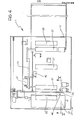
housing 2 of themachine 1 has an upper pair of guides along which acarriage 53 is movable, the original 0 being laid carefully on the carriage and held firm by a raisable blanket substantially identical to that indicated 6 in Figures 1 and 2. - The
carriage 53 is movable in a longitudinal direction relative to thehousing 2 between two end positions one of which (starting position) is illustrated in full outline and indicated S in Figure 6 and the other of which (end of stroke position) is illustrated in broken outline and indicated T in the same drawing. - The cassette C for feeding the sheets P and the cassette G for collecting the reproductions are aligned, on opposite sides of the
housing 2 in the longitudinal direction of movement of thecarriage 53. - )Two parallel cylindrical guides 54 and 55 are located within the
housing 2 and extend in directions perpendicular to the direction of sliding of thecarriage 53. - A
further carriage 56 is movable on theguides - Figures 6 and 7 schematically show the arrangement on the
carriage 56 of a pair of broad spectrumlight sources 57, an objective 58 and a bank of threechromatic filters filters photodetector 62, for example an amorphous silicon photodetector, arranged to generate electrical signals indicative of the intensity of the radiation incident thereon. The displacement of thefilters motor 63 mounted on thecarriage 56. - As described in detail with reference to the embodiment of Figure 1, the
lamps 57 are intended to illuminate the original 0 so as to generate reflected radiation which is captured by the objective 58. The objective 58 transmits this reflected radiation to thephotodetector 62 through one of thefilters motor 63. - Again in this case, the intensity of the radiation incident on the
photodetector 62 when theblue filter 59 is associated with the objective 58 is indicative of the yellow content of the elementary area of the original 0 being scanned, at that moment, while the magenta and cyan chromatic components of the same elementary area are detected by associating thegreen filter 60 orred filter 61 respectively, with the objective 58. - The configuration described in Figure 7 differs from that illustrated in Figures 1 and 2 in that the objective 58 and the elements associated therewith are able to scan simultaneously only a fraction of an elementary line of the original 0.
- In order to scan a single elementary line (or more lines simultaneously) it is thus necessary to impart an alternating scanning movement to the
carriage 56 along theguides - A further difference is that in the embodiment of Figures 1 and 2, the original 0 is located on a
transparent plate 5 which is fixed relative to thehousing 2 while in the embodiment of Figure 7, thecarriage 53, which is also provided underneath with a transparent surface (thus making possible the scanning of the original 0 by the photosensor devices mounted on the carriage 56), is movable longitudinally relative to thehousing 2. - In the embodiment of Figure 6, the scanning of the original 0 is thus achieved as a result of the superposition of the movement of the
carriage 53 and the movement of thecarriage 56 mounted on theguides - As is best seen in Figure 8, the movement of the
carriage 56 takes place between a start of stroke position illustrated in full outline and indicated U, and an end of stroke position illustrated in broken outline and indicated V. -
Reference 64 indicates a thermal printing head supported on a carriage entrained by thecarriage 56 in its back and forth movement along theguides - A feed device generally indicated 65 is arranged to take up sheets P from the cassette C and transfer these sheets longitudinally of the
housing 2 towards the collecting cassette G which, as indicated above, is located on the opposite side of thehousing 2. -
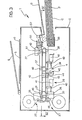
Reference 66 indicates a container (cassette or cartridge) within which are twospools print ribbon 69 substantially identical to theribbon 29 of the container.32. - As is seen in Figure 6, the loaded position of the
container 66 within thehousing 2 is such that the axes of thespools carriage 53 carrying the original. - The
container 66 is shaped so that a portion of the ribbon 69 (active portion), of a length substantially corresponding to the working stroke of thecarriage 56, lies in a plane parallel to the plane in which the original 0 is located on thecarriage 53. - In the loaded position, this active portion of the ribbon is located between the
printing head 64 supported by thecarriage 56 and the plane of sliding of the sheets P in thefeed device 65. - The
head 64 which is mounted on thecarriage 56 by means of apivotal bracket 70 operated by arelay 71, is thus able to press the active portion of theribbon 69 against the sheet P supplied by thefeed device 65. - The pressure exerted by the
head 64 is opposed by a resilientlyyieldable support 72 which extends over the entire region in which the head operates. - In the example illustrated, the
feed device 65 includes a sheet take-up roller 73, threedrive rollers 74, two of which extend along the sides of thesupport element 72, and a pair ofexpulsion rollers 75. - The
rollers 74 lie beneath correspondingcounter rollers 76 and are rotated via a gear wheel and worm screw coupling from adrive pulley 77 which is, in turn, connected, for example through a belt transmission, to the drive mechanism of thecarriage 53 on which the original 0 is mounted.. - In this manner it is ensured that each of the sheets P taken from the cassette C is advanced beneath the active portion of the
ribbon 69 on which theprinting head 64 acts, at a speed of advance corresponding to the speed of movement of thecarriage 53. - As has been seen above, the trichromatic reproduction of the original 0 on the sheets P requires three successive scanning operations, for detecting the three primary chromatic components of the original and three successive printing operations for reproducing the chromatic components on the sheet P. The number of scanning and printing operations rises to four whenever it is desired to enrich the trichromatic reproduction with a black and white print.
- In the embodiments of Figures 1 and 2, the operations of scanning and printing one chromatic component are carried out over the entire surface of the original 0 and over the entire surface of the sheet P before passing on to the operations of scanning and printing a different chromatic component. This makes it necessary to recirculate a single sheet P previously output.
- In the embodiment of Figure 6, the reproduction of the original is carried out by scanning three (four, in the case of enrichment with black and white) times across each line of the original and effecting simultaneously with each scanning of the original 0, the printing of the appropriate chromatic component for the corresponding line on the sheet P.
- In this manner, the trichromatic reproduction of each of the lines of the original 0 is completed before the trichromatic reproduction of the next line.
- The embodiment of Figure 6 thus avoids the necessity for the exact repositioning of the sheet P between two successive operations of scanning and printing two different chromatic components.
- Accuracy of reproduction is ensured by making the movement of the
rollers 74 driving the advance of the sheet P subservient to the drive mechanism of thecarriage 53 on which the original is located. - In this case it is sufficient to ensure precise initial positioning of the sheet P. This may be achieved by associating the device for driving the
rollers 74 with a photodetector which, in a similar manner to thephotodetector 39 of.Figure 3, is arranged to detect the position reached by one of the margins of the sheet P. - The scanning movement of the original by the objective 58 and the scanning movement of the sheet P by the
head 64 are thus strictly synchronised since both the objective 58 and theprinting head 64 are supported by thecarriage 56. The movement of thecarriage 56 is effected by means of a belt transmission 79 (Figure 7) driven by a motor, for example a d.c. or stepping motor, that has a different rotational speed in its two senses of rotation whereby to permit rapid return of thecarriage 56 from its end of stroke position V to its starting position U at the end of each scanning and printing stroke. - As is best seen in Figure 8, the
printing head 64 draws with it aroller 80 for detaching theribbon 69 from the sheet P so that the advancement of theribbon 69 and the longitudinal advance of the sheet P are not hindered. - The
thermal print ribbon 69 carries,a deposit of heat meltable ink arranged in an ordered succession of consecutive frames of different colours, each frame having a length equal to the transverse extent of the sheet P. - In the
ribbon 69, frames of yellow, magenta and cyan, that is, the colours used for trichromatic printing, alternate cyclically. In the case of trichromatic reproduction enriched with black and white printing, two successive groups of coloured frames of theribbon 69 have a black ink frame between them. - Preferably the
printing head 64 is raised from theribbon 69 by operation of therelay 71 between two successive scans so as not to obstruct the sliding of the ribbon itself and change over between two differently-coloured frames. - Raising of the
printing head 64 and its withdrawal from theribbon 69 is also effected during the removal of thecontainer 66 from the machine in order to allow the replacement of the ribbon. - From the foregoing description it can be seen that.the invention allows colour copying machines to be made which are very reliable and can ensure considerable consistency of results with time without adjustment. The use of a digital printing system allows machines embodying the invention to have different functions added, such as for example, printing or remote transmission of images.
- For this purpose it is possible to provide copying machines embodying the invention with a switch which deactivates the
portion 3 intended for the detection of the chromatic characteristics of an original. - The
reproduction portion 4 may then be connected remotely to thescanning portion 3 of a similar machine at a remote location so as to act as a telecopier. - It is also possible to connect the
reproduction portion 4 to any other source of numerical data relating to an image, such as an electronic processor, or to a disc or tape on which is stored, after a possible intermediate processing operation, data collected by a photosensor during scanning of the image to be reproduced. - In this case, the apparatus of the invention is thus operated as a colour printer.
Claims (35)
to produce relative movement between the printing means (27; 64, 69) and the substrate (P) during repeated scanning operations each of which results in the reproduction of a respective one of the chromatic components of the image (0) on corresponding areas of the substrate (P), and
the said drive means being further arranged to act on the photosensor means (11 to 16; 18 to 25; 57 to 63) such as to produce, during said repeated scanning operations, relative movement between the photosensor means (11 to 16; 18 to 25; 57 to 62) and the image (0), this latter relative movement being effected simultaneously and in coordination with the said relative movement between the printing means (27; 64, 69) and the substrate (P), whereby the photosensor means (11 to 16; 18 to 25; 57 to 62) and the printing means (27; 64, 69) act simultaneously on corresponding. regions of the image (0) and of the substrate (P).
the substrate feed device (65) being arranged to impart to the substrate (P) an advancing movement, relative to the carriage (56), that is in the same direction as, and synchronised with, the movement of the flat support element (53); and the printing means (64, 69) being at least partially supported by the movable carriage (56) so as to be interposed between the carriage (56) itself and the substrate feed device (65).
Applications Claiming Priority (2)
| Application Number | Priority Date | Filing Date | Title |
|---|---|---|---|
| IT6714683 | 1983-02-10 | ||
| IT67146/83A IT1203665B (en) | 1983-02-10 | 1983-02-10 | PROCEDURE AND EQUIPMENT FOR THE REPRODUCTION OF COLOR IMAGES |
Publications (3)
| Publication Number | Publication Date |
|---|---|
| EP0119166A2 true EP0119166A2 (en) | 1984-09-19 |
| EP0119166A3 EP0119166A3 (en) | 1986-04-02 |
| EP0119166B1 EP0119166B1 (en) | 1989-05-31 |
Family
ID=11299967
Family Applications (1)
| Application Number | Title | Priority Date | Filing Date |
|---|---|---|---|
| EP84830019A Expired EP0119166B1 (en) | 1983-02-10 | 1984-01-24 | Apparatus for reproducing coloured images |
Country Status (4)
| Country | Link |
|---|---|
| US (1) | US4651198A (en) |
| EP (1) | EP0119166B1 (en) |
| JP (1) | JPS59209197A (en) |
| IT (1) | IT1203665B (en) |
Cited By (2)
| Publication number | Priority date | Publication date | Assignee | Title |
|---|---|---|---|---|
| EP0291042A2 (en) * | 1987-05-13 | 1988-11-17 | Mita Industrial Co. Ltd. | Document scanning machine |
| EP0366380A2 (en) * | 1988-10-24 | 1990-05-02 | Mitsubishi Denki Kabushiki Kaisha | Image scanning and printing apparatus |
Families Citing this family (3)
| Publication number | Priority date | Publication date | Assignee | Title |
|---|---|---|---|---|
| JPS6211687A (en) * | 1985-07-10 | 1987-01-20 | Shinko Electric Co Ltd | Printing method in thermal transfer color printer |
| JP2502591B2 (en) * | 1987-05-13 | 1996-05-29 | 株式会社リコー | Document position detector |
| US5754314A (en) * | 1994-07-13 | 1998-05-19 | Nikon Corporation | Image input system and method for reading images from an original document |
Citations (4)
| Publication number | Priority date | Publication date | Assignee | Title |
|---|---|---|---|---|
| US4101216A (en) * | 1974-12-13 | 1978-07-18 | Gretag Aktiengesellschaft | Method and apparatus for print exposure control |
| GB1540525A (en) * | 1976-02-25 | 1979-02-14 | Hell R Gmbh | Apparatus for producing corrected colour separations |
| GB2007377A (en) * | 1977-10-22 | 1979-05-16 | Agfa Gevaert Ag | Method of and a device for determining the copy light intensity requirement when copying colour print material |
| US4161749A (en) * | 1978-03-30 | 1979-07-17 | Polaroid Corporation | Printer for producing print of an electronically recorded image |
Family Cites Families (11)
| Publication number | Priority date | Publication date | Assignee | Title |
|---|---|---|---|---|
| US3972608A (en) * | 1973-08-01 | 1976-08-03 | Canon Kabushiki Kaisha | Color copying apparatus having one or more screen-like photosensitive members |
| US4487407A (en) * | 1979-10-03 | 1984-12-11 | Xerox Corporation | Trail edge copy registration system |
| JPS56129476A (en) * | 1980-03-14 | 1981-10-09 | Canon Inc | Copy machine |
| US4476486A (en) * | 1980-12-16 | 1984-10-09 | Canon Kabushiki Kaisha | Image recording system utilizing a plurality of recording units |
| JPS57107858A (en) * | 1980-12-26 | 1982-07-05 | Fuji Xerox Co Ltd | Bicolor copying machine |
| JPS57129749A (en) * | 1981-02-06 | 1982-08-11 | Fuji Photo Film Co Ltd | Method and device for bringing out medium tone in ink-jet printer |
| JPS57196657A (en) * | 1981-05-28 | 1982-12-02 | Keijiro Kubota | Optical facsimile device |
| JPS5830272A (en) * | 1981-08-18 | 1983-02-22 | Fuji Xerox Co Ltd | Fixed platen type original multicolor reader |
| JPS5875965A (en) * | 1981-10-31 | 1983-05-07 | Toshiba Corp | Color printer |
| JPS58182925A (en) * | 1982-04-21 | 1983-10-26 | Oki Electric Ind Co Ltd | Programmable counter |
| US4476496A (en) * | 1982-06-21 | 1984-10-09 | Image Communications Inc. | Linear motor facsimile machine |
-
1983
- 1983-02-10 IT IT67146/83A patent/IT1203665B/en active
-
1984
- 1984-01-24 EP EP84830019A patent/EP0119166B1/en not_active Expired
- 1984-02-06 US US06/577,341 patent/US4651198A/en not_active Expired - Fee Related
- 1984-02-10 JP JP59024246A patent/JPS59209197A/en active Pending
Patent Citations (4)
| Publication number | Priority date | Publication date | Assignee | Title |
|---|---|---|---|---|
| US4101216A (en) * | 1974-12-13 | 1978-07-18 | Gretag Aktiengesellschaft | Method and apparatus for print exposure control |
| GB1540525A (en) * | 1976-02-25 | 1979-02-14 | Hell R Gmbh | Apparatus for producing corrected colour separations |
| GB2007377A (en) * | 1977-10-22 | 1979-05-16 | Agfa Gevaert Ag | Method of and a device for determining the copy light intensity requirement when copying colour print material |
| US4161749A (en) * | 1978-03-30 | 1979-07-17 | Polaroid Corporation | Printer for producing print of an electronically recorded image |
Cited By (4)
| Publication number | Priority date | Publication date | Assignee | Title |
|---|---|---|---|---|
| EP0291042A2 (en) * | 1987-05-13 | 1988-11-17 | Mita Industrial Co. Ltd. | Document scanning machine |
| EP0291042A3 (en) * | 1987-05-13 | 1992-01-29 | Mita Industrial Co. Ltd. | Document scanning machine |
| EP0366380A2 (en) * | 1988-10-24 | 1990-05-02 | Mitsubishi Denki Kabushiki Kaisha | Image scanning and printing apparatus |
| EP0366380A3 (en) * | 1988-10-24 | 1991-09-25 | Mitsubishi Denki Kabushiki Kaisha | Image scanning and printing apparatus |
Also Published As
| Publication number | Publication date |
|---|---|
| EP0119166B1 (en) | 1989-05-31 |
| IT1203665B (en) | 1989-02-15 |
| JPS59209197A (en) | 1984-11-27 |
| US4651198A (en) | 1987-03-17 |
| EP0119166A3 (en) | 1986-04-02 |
| IT8367146A0 (en) | 1983-02-10 |
Similar Documents
| Publication | Publication Date | Title |
|---|---|---|
| US4957689A (en) | Scanning and printing apparatus | |
| US4755877A (en) | Apparatus for reading and printing on a recording medium | |
| JPH01255542A (en) | Forming device for color picture image | |
| GB2152326A (en) | Document reading apparatus utilizing printer mechanism | |
| JPH02109049A (en) | Color scanner | |
| US4517591A (en) | Color printing apparatus | |
| JPH0226433B2 (en) | ||
| EP0119166B1 (en) | Apparatus for reproducing coloured images | |
| JPS58173963A (en) | Two color copying machine | |
| EP0602284A1 (en) | A thermal image-recording apparatus with sensor means for sensing the type of print sheet | |
| US4835603A (en) | Color image reproduction apparatus and a composite light filter and ink ribbon for use therein | |
| EP0066625B1 (en) | Thermal printing copy machine | |
| US4695896A (en) | Image forming apparatus | |
| JPS6016763A (en) | Printer | |
| JP2601800B2 (en) | Image forming device | |
| JP2925176B2 (en) | Image input device | |
| JP2565873B2 (en) | Image forming device | |
| JPS6382764A (en) | Image-forming device | |
| JPH0537730A (en) | Image forming device | |
| JPS6319970A (en) | Image forming device | |
| JPS6348073A (en) | Image forming device | |
| JPH04304065A (en) | Image forming device | |
| JPH03112678A (en) | Image forming device | |
| JPS6384271A (en) | Picture forming device | |
| JPH03266671A (en) | Image formation device |
Legal Events
| Date | Code | Title | Description |
|---|---|---|---|
| PUAI | Public reference made under article 153(3) epc to a published international application that has entered the european phase |
Free format text: ORIGINAL CODE: 0009012 |
|
| AK | Designated contracting states |
Designated state(s): CH FR GB LI NL |
|
| PUAL | Search report despatched |
Free format text: ORIGINAL CODE: 0009013 |
|
| RHK1 | Main classification (correction) |
Ipc: G03G 15/32 |
|
| AK | Designated contracting states |
Kind code of ref document: A3 Designated state(s): CH FR GB LI NL |
|
| 17P | Request for examination filed |
Effective date: 19860802 |
|
| 17Q | First examination report despatched |
Effective date: 19880718 |
|
| GRAA | (expected) grant |
Free format text: ORIGINAL CODE: 0009210 |
|
| AK | Designated contracting states |
Kind code of ref document: B1 Designated state(s): CH FR GB LI NL |
|
| PG25 | Lapsed in a contracting state [announced via postgrant information from national office to epo] |
Ref country code: LI Effective date: 19890531 Ref country code: CH Effective date: 19890531 |
|
| ET | Fr: translation filed | ||
| REG | Reference to a national code |
Ref country code: CH Ref legal event code: PL |
|
| PGFP | Annual fee paid to national office [announced via postgrant information from national office to epo] |
Ref country code: NL Payment date: 19900131 Year of fee payment: 7 |
|
| PLBE | No opposition filed within time limit |
Free format text: ORIGINAL CODE: 0009261 |
|
| STAA | Information on the status of an ep patent application or granted ep patent |
Free format text: STATUS: NO OPPOSITION FILED WITHIN TIME LIMIT |
|
| 26N | No opposition filed | ||
| PG25 | Lapsed in a contracting state [announced via postgrant information from national office to epo] |
Ref country code: NL Effective date: 19910801 |
|
| NLV4 | Nl: lapsed or anulled due to non-payment of the annual fee | ||
| PGFP | Annual fee paid to national office [announced via postgrant information from national office to epo] |
Ref country code: FR Payment date: 19930111 Year of fee payment: 10 |
|
| PGFP | Annual fee paid to national office [announced via postgrant information from national office to epo] |
Ref country code: GB Payment date: 19930112 Year of fee payment: 10 |
|
| PG25 | Lapsed in a contracting state [announced via postgrant information from national office to epo] |
Ref country code: GB Effective date: 19940124 |
|
| GBPC | Gb: european patent ceased through non-payment of renewal fee |
Effective date: 19940124 |
|
| PG25 | Lapsed in a contracting state [announced via postgrant information from national office to epo] |
Ref country code: FR Effective date: 19940930 |
|
| REG | Reference to a national code |
Ref country code: FR Ref legal event code: ST |