EP0119666A1 - Electrodeless discharge lamp - Google Patents
Electrodeless discharge lamp Download PDFInfo
- Publication number
- EP0119666A1 EP0119666A1 EP84200389A EP84200389A EP0119666A1 EP 0119666 A1 EP0119666 A1 EP 0119666A1 EP 84200389 A EP84200389 A EP 84200389A EP 84200389 A EP84200389 A EP 84200389A EP 0119666 A1 EP0119666 A1 EP 0119666A1
- Authority
- EP
- European Patent Office
- Prior art keywords
- lamp
- amalgam
- holder
- core
- electrodeless discharge
- Prior art date
- Legal status (The legal status is an assumption and is not a legal conclusion. Google has not performed a legal analysis and makes no representation as to the accuracy of the status listed.)
- Granted
Links
Images
Classifications
-
- H—ELECTRICITY
- H01—ELECTRIC ELEMENTS
- H01J—ELECTRIC DISCHARGE TUBES OR DISCHARGE LAMPS
- H01J65/00—Lamps without any electrode inside the vessel; Lamps with at least one main electrode outside the vessel
- H01J65/04—Lamps in which a gas filling is excited to luminesce by an external electromagnetic field or by external corpuscular radiation, e.g. for indicating plasma display panels
- H01J65/042—Lamps in which a gas filling is excited to luminesce by an external electromagnetic field or by external corpuscular radiation, e.g. for indicating plasma display panels by an external electromagnetic field
- H01J65/048—Lamps in which a gas filling is excited to luminesce by an external electromagnetic field or by external corpuscular radiation, e.g. for indicating plasma display panels by an external electromagnetic field the field being produced by using an excitation coil
Definitions
- the invention relates to an electrodeless discharge lamp comprising a lamp vessel which is sealed in a vacuum-tight manner and is filled with mercury and a rare gas, this lamp being provided with a core of magnetic material in which a high-frequency magnetic field can be induced by means of an electric supply unit and a coil wound around the core, an electric discharge being produced in the lamp vessel and further a holder with an amalgam being disposed in said lamp vessel.
- a lamp is known from the British published Patent Application 2,039,138 A.
- an amalgam is present at a comparatively cool area in the lamp vessel, in order to stabilize the mercury vapour pressure at a value of approximately 1 Pa during operation of the lamp.
- the conversion of electric energy into ultraviolet radiation mainly resonance radiation of mercury having a wavelength of 254 nm
- the amalgam in the lamp vessel of the known lamp is preferably provided in a holder which is located in the exhaust tube of said lamp vessel.
- the invention has for its object to provide an electrodeless gas discharge lamp in which the aforementioned disadvantage is avoided.
- an electrodeless gas discharge lamp of the kind mentioned in the opening paragraph is characterized in that the holder with the amalgam is located at the level of the coil wound around the core at an area in the lamp vessel at a certain distance from the core and the wall of said vessel, whereby the holder is situated in the discharge immediately after the lamp has been switched on and the amalgam is heated by the discharge., while in the stable operating condition the holder essentially comprises only amalgam-producing metal and substantially no longer comprises mercury.
- the holder is located at an area in the lamp vessel at which the intensity of the discharge during operation is comparatively high.
- the amalgam is then heated rapidly, whereby especially after the lamp has been switched on, substantially the whole quantity of mercury is released from the amalgam and is taken up by the discharge. In the lamp, a comparatively high light output is obtained a short time after the lamp has been switched on.
- the lamp vessel of the electrodeless lamp is shaped so that during operation of the lamp the discharge is produced toroidally around the core.
- the mercury released from the amalgam remains in the discharge for a comparatively long time, whereby substantially no condensation of mercury occurs on an adjacent cool part of the wall of the lamp envelope. Condensation substantially does not occur either on the core itself or on the parts of the wall of the lamp vessel located around the core.
- the amalgam is not disposed on the core itself or on a wall part located around the core. It has been found that the temperature of these parts is too low to obtain the desired effect. This especially applies if the core is provided with a heat-conducting body (see NL-TV 8104223, PHN.10142).
- the holder is secured on a supporting member which is secured to the wall of the lamp vessel.
- the holder then remains fixed during operation of the lamp in its position at the centre of the discharge.
- the core of magnetic material is preferably rod-shaped and is located in a tubular indentation in the wall of the lamp vessel, the supporting member being secured to the wall of the indentation.
- the supporting member (which preferably takes the form of a wire) can be provided in a comparatively simple manner.
- the supporting member is secured to the wall by means of, for example, glas enamel.
- the holder for the amalgam has, for example, the form of a plate-shaped body.
- the amalgam is preferably contained in a holder which is in the form of a wire network of a metal or an alloy (such as a chromium-nickel-iron alloy).
- a wire network can be manufactured in a simple manner and has a comparatively low heat capacity, as a result of which the heat produced by the discharge is taken up substantially completely by the amalgam, mercury then being released readily.
- the amalgam present in or on the holder preferably consists of a mercury alloy, from which, when the lamp is switched on, mercury is released readily upon heating. Favourable results were then obtained with an amalgam consisting of indium and mercury.
- a lamp according to the invention may have such a light output, shape, and colour rendition that it is suitable to serve as an alternative for incandescent lamps for general illumination purposes, as used, for example, in private houses.
- the lamp shown in the Figure comprises a glass lamp vessel which is sealed in a vacuum-tight manner and is filled with a quantity of mercury and a rare gas, such as krypton. Further, there is disposed on the inner wall of the lamp vessel a layer 2 of luminescent material, by means of which the ultraviolet radiation produced in the lamp envelope is converted into visible light. In a tubular indentation 3 in the wall of the lamp vessel there is disposed a rod-shaped core 4 of magnetic material.
- an electric supply unit 5 which is disposed in a housing 6 (preferably of synthetic material) which is partly of conical form and is provided with a sleeve 13
- a high-frequency magnetic field is induced in the core during operation of the lamp by means of a coil 7 connected to the supply unit (not visible in the drawing) and wound around this core. An electric discharge is then produced in the lamp vessel.
- a wire-shaped supporting member 8 is secured to the wall of the indentation 3, which supporting member is provided at a predetermined distance from the outer wall of the lamp envelope and the core with a holder 9 which is in the form of a wire network of a metal alloy (such as chromium-nickel-iron) in which an amalgam 10 is contained.
- a metal alloy such as chromium-nickel-iron
- the holder is located at the same level as the coil. However, in another embodiment, the holder may alternatively be located in an imaginary horizontal plane, which lies just below or just above the coil (for example, approximately 10% of the coil length value).
- the holder 9 is located in the discharge and is influenced by the temperature (approximately 300°C) of the discharge, whereby the holder substantially no longer contains mercury in the stable operating condition of the lamp. Substantially the whole quantity of mercury has been released from the amalgam, whereby essentially only amalgam-producing metal (such as indium or an alloy of indium and bismuth) is present in the holder.
- the holder 9 is located approximately halfway between the outer wall of the lamp vessel and the wall part 3 (preferably 1/5 to 4/5 of this distance), it being prevented that immediately after switching-on, the mercury released from the amalgam in the holder is condensed on the wall. When the lamp is switched off, the mercury returns to the holder, an amalgam then again being formed.
- the lamp vessel contains a second amalgam 11 for regulating the mercury vapour pressure during the operation of the lamp.
- This amalgam is disposed in a recess 12 at a comparatively cool area in the inner wall.
- the amalgam 11 consists of an alloy of lead, tin, bismuth and mercury (see US-PS 4,093,889, PHN.8319).
- the glass lamp vessel has a diameter of approximately 65 mm and a length of approximately 70 mm.
- the amalgam 10 contains approximately 1.5 mg of In and 2 mg of Hg.
- the lamp vessel further contains krypton at a pressure of approximately 70 Pa.
- the luminescent layer 2 consists of a mixture of two phosphors, i.e. green luminescing terbium-activated cerium-magnesium aluminate and red luminescing yttrium oxide activated by trivalent europium.
- the magnetic material of the rod-shaped core consists of a ferrite having a relative permeability of approximately 200 ("Philips 4M2" ferrite).
- a high-frequency oscillator having a frequency of approximately 3 MHz.
- a heat-conducting rod (not visible in the drawing) according to NL-TV 8104223 is present therein.
- the amalgam (180 mg) regulating the vapour pressure consisted of an alloy of Pb-Sn-Bi-Hg (ratio in % by weight 20 : 34 : 46 : 3).
- the luminous flux was 900 lumen.
Abstract
Description
- The invention relates to an electrodeless discharge lamp comprising a lamp vessel which is sealed in a vacuum-tight manner and is filled with mercury and a rare gas, this lamp being provided with a core of magnetic material in which a high-frequency magnetic field can be induced by means of an electric supply unit and a coil wound around the core, an electric discharge being produced in the lamp vessel and further a holder with an amalgam being disposed in said lamp vessel. Such a lamp is known from the British published Patent Application 2,039,138 A.
- In the lamp described in this published Patent Application, an amalgam is present at a comparatively cool area in the lamp vessel, in order to stabilize the mercury vapour pressure at a value of approximately 1 Pa during operation of the lamp. At a mercury vapour pressure of approximately 1 Pa, the conversion of electric energy into ultraviolet radiation (mainly resonance radiation of mercury having a wavelength of 254 nm) is at optimum. The amalgam in the lamp vessel of the known lamp is preferably provided in a holder which is located in the exhaust tube of said lamp vessel.
- One of the problems which arise in an electrodeless lamp, especially in such a lamp whose lamp vessel is provided with an amalgam regulating the mercury vapour pressure, is that especially after the ignition a comparatively long period of time elapses before the correct optimum vapour pressure is reached. Of course, the light output during this time is adversely affected thereby.
- The invention has for its object to provide an electrodeless gas discharge lamp in which the aforementioned disadvantage is avoided.
- According to the invention, an electrodeless gas discharge lamp of the kind mentioned in the opening paragraph is characterized in that the holder with the amalgam is located at the level of the coil wound around the core at an area in the lamp vessel at a certain distance from the core and the wall of said vessel, whereby the holder is situated in the discharge immediately after the lamp has been switched on and the amalgam is heated by the discharge., while in the stable operating condition the holder essentially comprises only amalgam-producing metal and substantially no longer comprises mercury.
- In the lamp according to the invention, the holder is located at an area in the lamp vessel at which the intensity of the discharge during operation is comparatively high. The amalgam is then heated rapidly, whereby especially after the lamp has been switched on, substantially the whole quantity of mercury is released from the amalgam and is taken up by the discharge. In the lamp, a comparatively high light output is obtained a short time after the lamp has been switched on.
- The lamp vessel of the electrodeless lamp is shaped so that during operation of the lamp the discharge is produced toroidally around the core. In order to obtain an optimum light output, there is a comparatively large distance between the core at the area of the winding coil and the outer wall of the lamp vessel. The mercury released from the amalgam remains in the discharge for a comparatively long time, whereby substantially no condensation of mercury occurs on an adjacent cool part of the wall of the lamp envelope. Condensation substantially does not occur either on the core itself or on the parts of the wall of the lamp vessel located around the core. The amalgam is not disposed on the core itself or on a wall part located around the core. It has been found that the temperature of these parts is too low to obtain the desired effect. This especially applies if the core is provided with a heat-conducting body (see NL-TV 8104223, PHN.10142).
- In a practical embodiment of the lamp according to the invention, the holder is secured on a supporting member which is secured to the wall of the lamp vessel. The holder then remains fixed during operation of the lamp in its position at the centre of the discharge.
- In the lamp according to the invention, the core of magnetic material is preferably rod-shaped and is located in a tubular indentation in the wall of the lamp vessel, the supporting member being secured to the wall of the indentation. During the manufacture of the lamp, the supporting member (which preferably takes the form of a wire) can be provided in a comparatively simple manner. The supporting member is secured to the wall by means of, for example, glas enamel.
- The holder for the amalgam has, for example, the form of a plate-shaped body. The amalgam is preferably contained in a holder which is in the form of a wire network of a metal or an alloy (such as a chromium-nickel-iron alloy). Such a wire network can be manufactured in a simple manner and has a comparatively low heat capacity, as a result of which the heat produced by the discharge is taken up substantially completely by the amalgam, mercury then being released readily.
- The amalgam present in or on the holder preferably consists of a mercury alloy, from which, when the lamp is switched on, mercury is released readily upon heating. Favourable results were then obtained with an amalgam consisting of indium and mercury.
- A lamp according to the invention may have such a light output, shape, and colour rendition that it is suitable to serve as an alternative for incandescent lamps for general illumination purposes, as used, for example, in private houses.
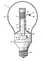
- The invention will be described more fully with reference to a drawing, which shows diagrammatically, partly in sectional view and partly in elevation, an embodiment of an electrodeless lamp according to the invention.
- The lamp shown in the Figure comprises a glass lamp vessel which is sealed in a vacuum-tight manner and is filled with a quantity of mercury and a rare gas, such as krypton. Further, there is disposed on the inner wall of the lamp vessel a
layer 2 of luminescent material, by means of which the ultraviolet radiation produced in the lamp envelope is converted into visible light. In atubular indentation 3 in the wall of the lamp vessel there is disposed a rod-shaped core 4 of magnetic material. By anelectric supply unit 5, which is disposed in a housing 6 (preferably of synthetic material) which is partly of conical form and is provided with asleeve 13, a high-frequency magnetic field is induced in the core during operation of the lamp by means of acoil 7 connected to the supply unit (not visible in the drawing) and wound around this core. An electric discharge is then produced in the lamp vessel. - At the level of the
coil 7, a wire-shaped supporting member 8 is secured to the wall of theindentation 3, which supporting member is provided at a predetermined distance from the outer wall of the lamp envelope and the core with a holder 9 which is in the form of a wire network of a metal alloy (such as chromium-nickel-iron) in which anamalgam 10 is contained. In the drawing, the holder is located at the same level as the coil. However, in another embodiment, the holder may alternatively be located in an imaginary horizontal plane, which lies just below or just above the coil (for example, approximately 10% of the coil length value). After the lamp has been switched on, the holder 9 is located in the discharge and is influenced by the temperature (approximately 300°C) of the discharge, whereby the holder substantially no longer contains mercury in the stable operating condition of the lamp. Substantially the whole quantity of mercury has been released from the amalgam, whereby essentially only amalgam-producing metal (such as indium or an alloy of indium and bismuth) is present in the holder. The holder 9 is located approximately halfway between the outer wall of the lamp vessel and the wall part 3 (preferably 1/5 to 4/5 of this distance), it being prevented that immediately after switching-on, the mercury released from the amalgam in the holder is condensed on the wall. When the lamp is switched off, the mercury returns to the holder, an amalgam then again being formed. - In the embodiment shown, the lamp vessel contains a
second amalgam 11 for regulating the mercury vapour pressure during the operation of the lamp. This amalgam is disposed in arecess 12 at a comparatively cool area in the inner wall. In a practical embodiment, theamalgam 11 consists of an alloy of lead, tin, bismuth and mercury (see US-PS 4,093,889, PHN.8319). - In a practical embodiment of a lamp of the kind described above, the glass lamp vessel has a diameter of approximately 65 mm and a length of approximately 70 mm. Before the lamp is switched on, the
amalgam 10 contains approximately 1.5 mg of In and 2 mg of Hg. The lamp vessel further contains krypton at a pressure of approximately 70 Pa. In the said embodiment, theluminescent layer 2 consists of a mixture of two phosphors, i.e. green luminescing terbium-activated cerium-magnesium aluminate and red luminescing yttrium oxide activated by trivalent europium. The magnetic material of the rod-shaped core consists of a ferrite having a relative permeability of approximately 200 ("Philips 4M2" ferrite). Thecoil 7 comprises approximately ten turns of copper wire (diameter 0.5 mm, L = approximately 4.5 /uH). There is provided in the electric supply unit 5 a high-frequency oscillator having a frequency of approximately 3 MHz. For cooling the core 4, a heat-conducting rod (not visible in the drawing) according to NL-TV 8104223 is present therein. The amalgam (180 mg) regulating the vapour pressure consisted of an alloy of Pb-Sn-Bi-Hg (ratio in % by weight 20 : 34 : 46 : 3). - When a power (inclusive supply) of approximately 15 W was supplied to the lamp, the luminous flux was 900 lumen.
Claims (7)
Applications Claiming Priority (2)
| Application Number | Priority Date | Filing Date | Title |
|---|---|---|---|
| NL8301032A NL8301032A (en) | 1983-03-23 | 1983-03-23 | ELECTRODELESS DISCHARGE LAMP. |
| NL8301032 | 1983-03-23 |
Publications (2)
| Publication Number | Publication Date |
|---|---|
| EP0119666A1 true EP0119666A1 (en) | 1984-09-26 |
| EP0119666B1 EP0119666B1 (en) | 1987-06-16 |
Family
ID=19841588
Family Applications (1)
| Application Number | Title | Priority Date | Filing Date |
|---|---|---|---|
| EP84200389A Expired EP0119666B1 (en) | 1983-03-23 | 1984-03-20 | Electrodeless discharge lamp |
Country Status (6)
| Country | Link |
|---|---|
| US (1) | US4622495A (en) |
| EP (1) | EP0119666B1 (en) |
| JP (1) | JPS59180956A (en) |
| CA (1) | CA1215101A (en) |
| DE (1) | DE3464297D1 (en) |
| NL (1) | NL8301032A (en) |
Cited By (9)
| Publication number | Priority date | Publication date | Assignee | Title |
|---|---|---|---|---|
| EP0307037A1 (en) * | 1987-09-08 | 1989-03-15 | Koninklijke Philips Electronics N.V. | Low-pressure mercury vapour discharge lamp |
| EP0327346A2 (en) * | 1988-02-02 | 1989-08-09 | Kabushiki Kaisha Toshiba | Amalgam suitable for use in a low mercury vapor pressure discharge lamp |
| EP0604221A1 (en) * | 1992-12-22 | 1994-06-29 | Flowil International Lighting (Holding) B.V. | Fluorescent lamp |
| EP0667636A2 (en) * | 1994-02-10 | 1995-08-16 | General Electric Company | Fluorescent lamp |
| EP0758795A1 (en) * | 1995-08-14 | 1997-02-19 | General Electric Company | Amalgam containing compact fluorescent lamp with improved warm-up |
| EP0769805A2 (en) * | 1995-10-18 | 1997-04-23 | General Electric Company | Electrodeless fluorescent lamp |
| EP0769803A2 (en) * | 1995-10-18 | 1997-04-23 | General Electric Company | Electrodeless fluorescent lamp |
| EP0688039A3 (en) * | 1994-06-13 | 1997-11-05 | General Electric Company | Fluorescent lamp and manufacture thereof |
| US7800289B2 (en) | 2005-10-20 | 2010-09-21 | Minebea Co., Ltd. | Electrodeless gas discharge lamp |
Families Citing this family (34)
| Publication number | Priority date | Publication date | Assignee | Title |
|---|---|---|---|---|
| NL8601702A (en) * | 1986-06-30 | 1988-01-18 | Philips Nv | ELECTRESSLESS LOW PRESSURE DISCHARGE LAMP. |
| US4922157A (en) * | 1987-06-26 | 1990-05-01 | U.S. Philips Corp. | Electrodeless low-pressure discharge lamp with thermally isolated magnetic core |
| US5118196A (en) * | 1990-03-05 | 1992-06-02 | Ault David J | Electromagnetic Christmas tree lights |
| JPH05234570A (en) * | 1991-06-28 | 1993-09-10 | Matsushita Electric Works Ltd | Electrodeless discharge lamp |
| US5306986A (en) * | 1992-05-20 | 1994-04-26 | Diablo Research Corporation | Zero-voltage complementary switching high efficiency class D amplifier |
| US5581157A (en) * | 1992-05-20 | 1996-12-03 | Diablo Research Corporation | Discharge lamps and methods for making discharge lamps |
| TW214598B (en) * | 1992-05-20 | 1993-10-11 | Diablo Res Corp | Impedance matching and filter network for use with electrodeless discharge lamp |
| US5397966A (en) * | 1992-05-20 | 1995-03-14 | Diablo Research Corporation | Radio frequency interference reduction arrangements for electrodeless discharge lamps |
| CA2137289A1 (en) * | 1992-06-05 | 1993-12-23 | Derek Bray | Electrodeless discharge lamp containing push-pull class e amplifier and bifilar coil |
| TW210397B (en) * | 1992-06-05 | 1993-08-01 | Diablo Res Corp | Base mechanism to attach an electrodeless discharge light bulb to a socket in a standard lamp harp structure |
| US5598069A (en) * | 1993-09-30 | 1997-01-28 | Diablo Research Corporation | Amalgam system for electrodeless discharge lamp |
| US5434482A (en) * | 1993-10-04 | 1995-07-18 | General Electric Company | Electrodeless fluorescent lamp with optimized amalgam positioning |
| EP0646942B1 (en) * | 1993-10-04 | 1997-06-04 | General Electric Company | Accurate placement and retention of an amalgam in an electrodeless fluorescent lamp |
| US5412288A (en) * | 1993-12-15 | 1995-05-02 | General Electric Company | Amalgam support in an electrodeless fluorescent lamp |
| US5412289A (en) * | 1993-12-15 | 1995-05-02 | General Electric Company | Using a magnetic field to locate an amalgam in an electrodeless fluorescent lamp |
| TW344018B (en) * | 1994-07-15 | 1998-11-01 | Philips Electronics Nv | Low-pressure mercury vapor discharge lamp |
| US5847508A (en) * | 1994-10-03 | 1998-12-08 | General Electric Company | Integrated starting and running amalgam assembly for an electrodeless fluorescent lamp |
| DE19512129A1 (en) * | 1995-03-31 | 1996-10-02 | Patent Treuhand Ges Fuer Elektrische Gluehlampen Mbh | Low pressure mercury vapor discharge lamp |
| TW344084B (en) * | 1995-05-24 | 1998-11-01 | Philips Eloctronics N V | Lighting unit, electrodeless low-pressure discharge lamp, and discharge vessel for use in the lighting unit |
| DE19643219A1 (en) * | 1995-10-23 | 1997-04-24 | Gen Electric | Amalgam holder arrangement for an electrodeless discharge lamp |
| US5773926A (en) * | 1995-11-16 | 1998-06-30 | Matsushita Electric Works Research And Development Laboratory Inc | Electrodeless fluorescent lamp with cold spot control |
| EP0811240B1 (en) * | 1995-12-21 | 2000-08-16 | Koninklijke Philips Electronics N.V. | Electrodeless low-pressure discharge lamp |
| US5698951A (en) * | 1996-05-06 | 1997-12-16 | Matsushita Electric Works Research & Development Labratory | Electrodeless discharge lamp and device for increasing the lamp's luminous development |
| DE69716855T2 (en) * | 1996-05-17 | 2003-07-03 | Koninkl Philips Electronics Nv | LOW PRESSURE MERCURY DISCHARGE LAMP |
| US6249090B1 (en) | 1996-07-03 | 2001-06-19 | Matsushita Electric Works Research & Development Laboratories Inc | Electrodeless fluorescent lamp with spread induction coil |
| US5717290A (en) * | 1996-09-26 | 1998-02-10 | Osram Sylvania Inc. | Starting flag structure for tubular low pressure discharge lamps |
| US5723947A (en) * | 1996-12-20 | 1998-03-03 | Matsushita Electric Works Research & Development Laboratories Inc. | Electrodeless inductively-coupled fluorescent lamp with improved cavity and tubulation |
| US5925987A (en) * | 1997-07-18 | 1999-07-20 | Hartmann & Braun Gmbh & Co. Kg | Printed circuit board mounted electrodeless gas discharge lamp |
| TW548681B (en) * | 1999-02-24 | 2003-08-21 | Koninkl Philips Electronics Nv | Low-pressure mercury vapor discharge lamp |
| JP4258380B2 (en) * | 2004-01-05 | 2009-04-30 | パナソニック電工株式会社 | Electrodeless fluorescent lamp and its lighting device |
| US8198815B2 (en) * | 2009-09-29 | 2012-06-12 | Osram Sylvania Inc. | Amalgam support in an inductively coupled discharge lamp |
| US8502482B1 (en) | 2011-12-06 | 2013-08-06 | John Yeh | Compact induction lamp |
| US9030088B2 (en) * | 2012-05-07 | 2015-05-12 | John Yeh | Induction fluorescent lamp with amalgam chamber |
| US9461222B1 (en) | 2015-06-30 | 2016-10-04 | Epistar Corporation | Light-emitting element and the light-emitting module thereof |
Citations (2)
| Publication number | Priority date | Publication date | Assignee | Title |
|---|---|---|---|---|
| US2016111A (en) * | 1933-10-30 | 1935-10-01 | William J Hitchcock | Gas discharge lamp, especially mercury lamp |
| DE2942735A1 (en) * | 1978-10-25 | 1980-04-30 | Gen Electric | DISCHARGE LAMP WITH SOURCE-FREE ELECTRIC FIELD |
Family Cites Families (6)
| Publication number | Priority date | Publication date | Assignee | Title |
|---|---|---|---|---|
| US3619697A (en) * | 1964-07-09 | 1971-11-09 | Westinghouse Electric Corp | Mercury vapor discharge lamp and pressure-regulating means therefor |
| US3504215A (en) * | 1967-11-30 | 1970-03-31 | Westinghouse Electric Corp | Planar fluorescent lamp with integral amalgam type mercury-vapor pressure control component |
| US3526803A (en) * | 1968-01-30 | 1970-09-01 | Westinghouse Electric Corp | High-output fluorescent lamp with axial rod and amalgam mercury-vapor control means |
| US4010400A (en) * | 1975-08-13 | 1977-03-01 | Hollister Donald D | Light generation by an electrodeless fluorescent lamp |
| NL177163C (en) * | 1976-03-04 | 1985-08-01 | Philips Nv | LOW-PRESSURE MERCURY DISCHARGE LAMP. |
| US4437041A (en) * | 1981-11-12 | 1984-03-13 | General Electric Company | Amalgam heating system for solenoidal electric field lamps |
-
1983
- 1983-03-23 NL NL8301032A patent/NL8301032A/en not_active Application Discontinuation
-
1984
- 1984-03-09 US US06/587,792 patent/US4622495A/en not_active Expired - Lifetime
- 1984-03-19 JP JP59053376A patent/JPS59180956A/en active Granted
- 1984-03-20 DE DE8484200389T patent/DE3464297D1/en not_active Expired
- 1984-03-20 EP EP84200389A patent/EP0119666B1/en not_active Expired
- 1984-03-22 CA CA000450263A patent/CA1215101A/en not_active Expired
Patent Citations (2)
| Publication number | Priority date | Publication date | Assignee | Title |
|---|---|---|---|---|
| US2016111A (en) * | 1933-10-30 | 1935-10-01 | William J Hitchcock | Gas discharge lamp, especially mercury lamp |
| DE2942735A1 (en) * | 1978-10-25 | 1980-04-30 | Gen Electric | DISCHARGE LAMP WITH SOURCE-FREE ELECTRIC FIELD |
Cited By (13)
| Publication number | Priority date | Publication date | Assignee | Title |
|---|---|---|---|---|
| EP0307037A1 (en) * | 1987-09-08 | 1989-03-15 | Koninklijke Philips Electronics N.V. | Low-pressure mercury vapour discharge lamp |
| EP0327346A2 (en) * | 1988-02-02 | 1989-08-09 | Kabushiki Kaisha Toshiba | Amalgam suitable for use in a low mercury vapor pressure discharge lamp |
| EP0327346A3 (en) * | 1988-02-02 | 1991-02-27 | Kabushiki Kaisha Toshiba | Amalgam suitable for use in a low mercury vapor pressure discharge lamp |
| EP0604221A1 (en) * | 1992-12-22 | 1994-06-29 | Flowil International Lighting (Holding) B.V. | Fluorescent lamp |
| EP0667636A3 (en) * | 1994-02-10 | 1997-03-12 | Gen Electric | Fluorescent lamp. |
| EP0667636A2 (en) * | 1994-02-10 | 1995-08-16 | General Electric Company | Fluorescent lamp |
| EP0688039A3 (en) * | 1994-06-13 | 1997-11-05 | General Electric Company | Fluorescent lamp and manufacture thereof |
| EP0758795A1 (en) * | 1995-08-14 | 1997-02-19 | General Electric Company | Amalgam containing compact fluorescent lamp with improved warm-up |
| EP0769805A2 (en) * | 1995-10-18 | 1997-04-23 | General Electric Company | Electrodeless fluorescent lamp |
| EP0769803A2 (en) * | 1995-10-18 | 1997-04-23 | General Electric Company | Electrodeless fluorescent lamp |
| EP0769803A3 (en) * | 1995-10-18 | 1999-02-03 | General Electric Company | Electrodeless fluorescent lamp |
| EP0769805A3 (en) * | 1995-10-18 | 1999-02-03 | General Electric Company | Electrodeless fluorescent lamp |
| US7800289B2 (en) | 2005-10-20 | 2010-09-21 | Minebea Co., Ltd. | Electrodeless gas discharge lamp |
Also Published As
| Publication number | Publication date |
|---|---|
| JPH0443382B2 (en) | 1992-07-16 |
| NL8301032A (en) | 1984-10-16 |
| JPS59180956A (en) | 1984-10-15 |
| DE3464297D1 (en) | 1987-07-23 |
| EP0119666B1 (en) | 1987-06-16 |
| CA1215101A (en) | 1986-12-09 |
| US4622495A (en) | 1986-11-11 |
Similar Documents
| Publication | Publication Date | Title |
|---|---|---|
| EP0119666B1 (en) | Electrodeless discharge lamp | |
| EP0074690B1 (en) | Electrodeless gas discharge lamp | |
| US4117378A (en) | Reflective coating for external core electrodeless fluorescent lamp | |
| EP0207333B1 (en) | Electrodeless high pressure sodium iodide arc lamp | |
| US5434482A (en) | Electrodeless fluorescent lamp with optimized amalgam positioning | |
| US6081070A (en) | High-frequency electrodeless fluorescent lamp | |
| EP0135960B1 (en) | Electrodeless metal vapour discharge lamp | |
| CA2241636C (en) | Electrodeless lamp having thermal bridge between transformer core and amalgam | |
| EP0646942B1 (en) | Accurate placement and retention of an amalgam in an electrodeless fluorescent lamp | |
| US5479072A (en) | Low mercury arc discharge lamp containing neodymium | |
| JPH0677445B2 (en) | High-efficiency electrodeless high-luminance discharge lamp that is easy to light | |
| JPS6337942B2 (en) | ||
| EP0769805A2 (en) | Electrodeless fluorescent lamp | |
| US5773926A (en) | Electrodeless fluorescent lamp with cold spot control | |
| US5363015A (en) | Low mercury arc discharge lamp containing praseodymium | |
| EP0413398A1 (en) | Electrodeless low-pressure mercury vapour discharge lamp | |
| US5559392A (en) | Apparatus for securing an amalgam at the apex of an electrodeless fluorescent lamp | |
| EP0833372A2 (en) | Starting flag structure for tubular low pressure discharge lamps | |
| US5847508A (en) | Integrated starting and running amalgam assembly for an electrodeless fluorescent lamp | |
| EP0157440B1 (en) | Low-pressure mercury vapour discharge lamp | |
| JPS6013264B2 (en) | fluorescent light | |
| US6249090B1 (en) | Electrodeless fluorescent lamp with spread induction coil | |
| US5760547A (en) | Multiple-discharge electrodeless fluorescent lamp | |
| CA2111426A1 (en) | Electrodeless lamp bulb | |
| CA1144224A (en) | High frequency electrodeless lamp having a gapped magnetic core and method |
Legal Events
| Date | Code | Title | Description |
|---|---|---|---|
| PUAI | Public reference made under article 153(3) epc to a published international application that has entered the european phase |
Free format text: ORIGINAL CODE: 0009012 |
|
| AK | Designated contracting states |
Designated state(s): BE DE FR GB NL |
|
| 17P | Request for examination filed |
Effective date: 19841120 |
|
| 17Q | First examination report despatched |
Effective date: 19860826 |
|
| GRAA | (expected) grant |
Free format text: ORIGINAL CODE: 0009210 |
|
| AK | Designated contracting states |
Kind code of ref document: B1 Designated state(s): BE DE FR GB NL |
|
| REF | Corresponds to: |
Ref document number: 3464297 Country of ref document: DE Date of ref document: 19870723 |
|
| ET | Fr: translation filed | ||
| PLBE | No opposition filed within time limit |
Free format text: ORIGINAL CODE: 0009261 |
|
| STAA | Information on the status of an ep patent application or granted ep patent |
Free format text: STATUS: NO OPPOSITION FILED WITHIN TIME LIMIT |
|
| 26N | No opposition filed | ||
| PGFP | Annual fee paid to national office [announced via postgrant information from national office to epo] |
Ref country code: NL Payment date: 19900331 Year of fee payment: 7 |
|
| PG25 | Lapsed in a contracting state [announced via postgrant information from national office to epo] |
Ref country code: NL Effective date: 19911001 |
|
| NLV4 | Nl: lapsed or anulled due to non-payment of the annual fee | ||
| PGFP | Annual fee paid to national office [announced via postgrant information from national office to epo] |
Ref country code: BE Payment date: 19950307 Year of fee payment: 12 |
|
| REG | Reference to a national code |
Ref country code: FR Ref legal event code: CD |
|
| PG25 | Lapsed in a contracting state [announced via postgrant information from national office to epo] |
Ref country code: BE Effective date: 19960331 |
|
| BERE | Be: lapsed |
Owner name: PHILIPS ELECTRONICS N.V. Effective date: 19960331 |
|
| REG | Reference to a national code |
Ref country code: FR Ref legal event code: CD |
|
| REG | Reference to a national code |
Ref country code: GB Ref legal event code: IF02 |
|
| PGFP | Annual fee paid to national office [announced via postgrant information from national office to epo] |
Ref country code: FR Payment date: 20020327 Year of fee payment: 19 |
|
| PGFP | Annual fee paid to national office [announced via postgrant information from national office to epo] |
Ref country code: GB Payment date: 20020328 Year of fee payment: 19 |
|
| PGFP | Annual fee paid to national office [announced via postgrant information from national office to epo] |
Ref country code: DE Payment date: 20020523 Year of fee payment: 19 |
|
| PG25 | Lapsed in a contracting state [announced via postgrant information from national office to epo] |
Ref country code: GB Free format text: LAPSE BECAUSE OF NON-PAYMENT OF DUE FEES Effective date: 20030320 |
|
| PG25 | Lapsed in a contracting state [announced via postgrant information from national office to epo] |
Ref country code: DE Free format text: LAPSE BECAUSE OF NON-PAYMENT OF DUE FEES Effective date: 20031001 |
|
| GBPC | Gb: european patent ceased through non-payment of renewal fee |
Effective date: 20030320 |
|
| PG25 | Lapsed in a contracting state [announced via postgrant information from national office to epo] |
Ref country code: FR Free format text: LAPSE BECAUSE OF NON-PAYMENT OF DUE FEES Effective date: 20031127 |
|
| REG | Reference to a national code |
Ref country code: FR Ref legal event code: ST |