EP0120410A2 - Ultrasonic probe device - Google Patents
Ultrasonic probe device Download PDFInfo
- Publication number
- EP0120410A2 EP0120410A2 EP84102798A EP84102798A EP0120410A2 EP 0120410 A2 EP0120410 A2 EP 0120410A2 EP 84102798 A EP84102798 A EP 84102798A EP 84102798 A EP84102798 A EP 84102798A EP 0120410 A2 EP0120410 A2 EP 0120410A2
- Authority
- EP
- European Patent Office
- Prior art keywords
- probe
- bag
- ultrasonic
- engaging portion
- liquid
- Prior art date
- Legal status (The legal status is an assumption and is not a legal conclusion. Google has not performed a legal analysis and makes no representation as to the accuracy of the status listed.)
- Granted
Links
Images


Classifications
-
- A—HUMAN NECESSITIES
- A61—MEDICAL OR VETERINARY SCIENCE; HYGIENE
- A61B—DIAGNOSIS; SURGERY; IDENTIFICATION
- A61B10/00—Other methods or instruments for diagnosis, e.g. instruments for taking a cell sample, for biopsy, for vaccination diagnosis; Sex determination; Ovulation-period determination; Throat striking implements
-
- A—HUMAN NECESSITIES
- A61—MEDICAL OR VETERINARY SCIENCE; HYGIENE
- A61B—DIAGNOSIS; SURGERY; IDENTIFICATION
- A61B17/00—Surgical instruments, devices or methods, e.g. tourniquets
- A61B17/22—Implements for squeezing-off ulcers or the like on the inside of inner organs of the body; Implements for scraping-out cavities of body organs, e.g. bones; Calculus removers; Calculus smashing apparatus; Apparatus for removing obstructions in blood vessels, not otherwise provided for
- A61B17/225—Implements for squeezing-off ulcers or the like on the inside of inner organs of the body; Implements for scraping-out cavities of body organs, e.g. bones; Calculus removers; Calculus smashing apparatus; Apparatus for removing obstructions in blood vessels, not otherwise provided for for extracorporeal shock wave lithotripsy [ESWL], e.g. by using ultrasonic waves
- A61B17/2251—Implements for squeezing-off ulcers or the like on the inside of inner organs of the body; Implements for scraping-out cavities of body organs, e.g. bones; Calculus removers; Calculus smashing apparatus; Apparatus for removing obstructions in blood vessels, not otherwise provided for for extracorporeal shock wave lithotripsy [ESWL], e.g. by using ultrasonic waves characterised by coupling elements between the apparatus, e.g. shock wave apparatus or locating means, and the patient, e.g. details of bags, pressure control of bag on patient
-
- A—HUMAN NECESSITIES
- A61—MEDICAL OR VETERINARY SCIENCE; HYGIENE
- A61B—DIAGNOSIS; SURGERY; IDENTIFICATION
- A61B8/00—Diagnosis using ultrasonic, sonic or infrasonic waves
- A61B8/42—Details of probe positioning or probe attachment to the patient
- A61B8/4272—Details of probe positioning or probe attachment to the patient involving the acoustic interface between the transducer and the tissue
- A61B8/4281—Details of probe positioning or probe attachment to the patient involving the acoustic interface between the transducer and the tissue characterised by sound-transmitting media or devices for coupling the transducer to the tissue
-
- G—PHYSICS
- G10—MUSICAL INSTRUMENTS; ACOUSTICS
- G10K—SOUND-PRODUCING DEVICES; METHODS OR DEVICES FOR PROTECTING AGAINST, OR FOR DAMPING, NOISE OR OTHER ACOUSTIC WAVES IN GENERAL; ACOUSTICS NOT OTHERWISE PROVIDED FOR
- G10K11/00—Methods or devices for transmitting, conducting or directing sound in general; Methods or devices for protecting against, or for damping, noise or other acoustic waves in general
- G10K11/004—Mounting transducers, e.g. provided with mechanical moving or orienting device
Definitions
- the present invention relates to an ultrasonic probe device adapted for use in ultrasonic diagnosis and, more specifically, to an ultrasonic probe device which is capable of easily interposing a liquid acoustical medium between an ultrasonic transmitting/receiving face of a probe and the surface of a subject to be examined.
- the movements of unborn babies, the defects or the internal organs of various portions of living bodies or organisms are observed as cross-sectional images by ultrasonic diagnoses.
- the surface of an organism is not even, but undulating.
- the ultrasonic transmitting/receiving face of a. probe may be regarded as substantially even and rigid. Accordingly, it is hard to acoustically couple the probe and organism by bringing the ultrasonic transmitting/receiving face into contact with the organism's surface. Thus, in some cases, it is impossible to send ultrasonic waves into the organism to detect ultrasonic echoes therefrom.
- the water bag is attached directly to the probe.
- the probe may be used singly, without being combined with the water bag.
- it is not easy to attach and detach the water bag to and from the probe.
- it is hard to pour water into the water bag or remove air bubbles therefrom.
- the probe and a living body may be coupled acoustically by interposing therebetween a filled, watertight rubber or vinyl bag. In this case, ultrasonic waves pass the rubber or vinyl sheet wall of the water bag twice. Therefore, the ultrasonic waves are greatly attenuated by the sheet wall.
- One object of the present invention is to provide an ultrasonic probe device facilitating the attachment of a liquid bag to a probe, or the detachment thereof from the probe.
- Another object of the invention is to provide an ultrasonic probe device accommodating the liquid-tight attachment of a liquid bag to a probe.
- Still another object of the invention is to provide an ultrasonic probe device capable of easily and speedily pouring liquid acoustical medium into a liquid bag, and removing air therefrom.
- a further object of the invention is to provide an ultrasonic probe device capable of the ultrasonic diagnoses of various parts of a subject to be examined with the reduced attenuation of ultrasonic waves.
- an ultrasonic probe device comprising a probe including a case having lateral faces and an ultrasonic transmitting/receiving face with at least one transmitting/receiving element contained in the case capable of transmitting and receiving ultrasonic waves.
- the case has a probe engaging portion on the lateral faces thereof.
- a liquid bag includes a container portion for containing a liquid acoustical medium, and a bag engaging portion composed of an elastic material so adapted as to engage with the probe engaging portion of the case.
- a fitting member includes an opening in which the container portion is fitted and a press portion on the periphery of the opening. The press portion has a shape to match the bag engaging portion.
- a clamp member clamps the fitting member against the probe engaging portion in such a manner that the container portion is fitted into the opening, and the press portion engages the probe engaging portion with the bag engaging portion lying therebetween.
- the liquid bag is attached to the probe by holding the bag engaging portion under pressure between the probe engaging portion and the press portion.
- the liquid bag can securely be attached to the case of the probe in a liquid-tight manner.
- the liquid bag can be easily and speedily attached to or detached from the probe by mounting or removing the fitting member. If a tube is attached to the container portion, feeding the liquid acoustic medium into the liquid bag and the removal of air therefrom may speedily be achieved with ease. Since the ultrasonic waves pass through the container portion only once, they attenuates only slightly.
- the ultrasonic probe device may be so constructed that the fitting member has a pair of hooked projections projecting from the press portion, the clamp member includes a main body capable of being retained on the case of the probe, and a pair of handles rockably attached to the main body and rockably fitted with retaining frames capable of engaging with the hooked projections, so that the sealing portion is held under pressure between the press portion and the step portion, as handles of the clamp member are rotated, causing the retaining frames to engage with the projections.
- the fitting member may be easily and speedily attached to the probe by merely rotating the handles.
- the fitting member may be reliably and stably attached, so that there is no possibility of its coming off the probe during ultrasonic diagnosis.
- Figs. 1 to 10 show an ultrasonic probe device according to one embodiment of the present invention.
- a probe 20 has a case 22 substantially in the form of a rectangular parallelepiped, which hermetically contains therein a plurality of elements for transmitting and receiving ultrasonic waves.
- the case 22 has gently sloping shoulder faces 24, upper lateral faces 26, lower lateral faces 28, and a bottom face or ultrasonic transmitting/receiving face 32.
- a cable 34 is led out from between the two shoulder faces 24 which transmits electrical signals to the ultrasonic transmitting/receiving elements and sends the signals therefrom to a signal processing system (not shown).
- a step portion 30 is formed between the upper and lower lateral faces 26, 28 in a manner such that the peripheral edges of the upper lateral faces 26 are longer than those of the lower lateral faces 28.
- a water bag 40 has a baglike container portion 42 for containing water which serves as an acoustical medium, and an engaging portion 44 which is integrally formed with respect to the container portion 42.
- the container portion 42 and engaging portion 44 are formed of a natural rubber, such as latex. Natural rubber is used since its acoustical characteristics resemble those of the human body, and since the water contained in such a container portion 42 produces less catoptric waves when ultrasonic waves are transmitted through the container portion 42.
- the wall of the container portion 42 is as thin as 0.1 to 0.2 mm, so that attenuation of the ultrasonic waves passing through the rubber sheet wall is minimized.
- the wall of the engaging portion 44 is relatively thick, being about 1 mm.
- the peripheral edges of the container portion 42, adjoining the engaging portion 44, are as long as or a little shorter than those of the lower lateral faces 28 of the probe 20.
- the peripheral edges of an opening 46 of the engaging portion 44 are as long as or a little shorter than those of the upper lateral faces 26 of the probe 20.
- the engaging portion 44 has a sealing portion 48 where it meets the container portion 42, and whereby the water bag 40 is constricted like a neck.
- the whole water bag 40 may be formed with a uniform wall thickness. In this case, the shortage of the thickness of the engaging portion 44 must be filled by covering the engaging portion 44 with a ring about 1 mm thick, which is shaped in conformity with the engaging portion 44 (including the sealing portion 48).
- the material of this ring is not limited to natural rubber and may be selected from among any elastic materials, including synthetic rubber.
- a water feeder 50 is attached to the flank of the container portion 42.
- This water feeder 50 includes a tube 52, attached to the flank of the container portion 42, for communicating with the space inside the container portion 42, and a connector 54 attached to the tube 52.
- the connector 54 is so adapted as to be fitted with an injector 100, whereby water or air may be injected into or removed from the water bag 40.
- the fitting member 60 is in the form of a shallow tray, and includes a peripheral press portion 62 and a rectangular engaging opening 68.
- a hooked retaining projection 64 is formed on the central portion of each of the shorter sides of the press member 62.
- the press portion 62 has a shape that matches the step portion 30 of the probe 20 and the engaging portion 44 (including the sealing portion 48) of the water bag 40.
- the fitting member 60 may be fitted to the probe 20 in such a way that the press portion 62 engages the sealing portion 48 of the water bag 40, as indicated by the broken lines of Fig. 5, after putting the engaging portion 44 of the water bag 40 on the upper lateral faces 26 of the probe 20, so that the sealing portion 48 can mate with the step portion 30.
- a clamp member 80 may be described as follows.
- the main body 82 of the clamp member 80 has a shape which matches the shoulder faces 24 and upper lateral faces 26 of the probe 20.
- the main body 82 includes a lateral plate 84 which serves to engage one of the upper lateral faces 26 of the probe 20, shoulder plates 86 which serve to engage the shoulder faces 24 of the probe 20, partial lateral plates 88 which are continuous with the individual shoulder plates 86 and which face the lateral plate 84, and support portions 90 which are continuous with the individual shoulder plates 86.
- a handle 92 is rockably supported at one end of each of the support portions 90 by means of a pin 94.
- a retaining frame 96 is rockably attached to the substantially central portion of the handle 92.
- the retaining frames 96 move up and down.
- the portions of the retaining frames 96 attached to the handles 92 are located inside the pins 94, with respect to the facing direction of the support portions 90.
- the fitting member 60 and the clamp member 80 must be composed of highly rigid materials to clamp the engaging portion 44 of the water bag 40 between these members 60, 80.
- these members 60, 80 should be composed of a cold-rolled steel sheet SPCC (JIS; ASTM A109-72), or other materials with high rigidity.
- the operation of the ultrasonic probe device 10 with the above-mentioned construction may be described as follows.
- the water bag 40 is attached to the probe 20.
- the engaging portion 44 of the water bag 40 is put on the upper lateral faces 26 of the probe 20, so that the sealing portion 48 of the water bag 40 engages with the step portion 30 of the probe 20.
- the fitting member 60 is put on the water bag 40 so that the container portion 42 is fitted into the opening 68, and the press portion 62 engages with the step portion 30 of the probe 20 with the engaging portion 44 therebetween.
- the clamp member 80 is fitted to the shoulder faces 24 of the probe 20.
- the handles 92 are rotated in the direction of the arrow 2 of Fig. 6 to lower the retaining frames 96.
- the handles 92 are rotated in the direction of the arrow 4 of Fig. 6, so as to abut against their corresponding support portions 90.
- the retaining frames 96 are lifted up so that the fitting member 60 and the clamp member 80 may clamp the water bag 40 against the probe 20.
- the retaining frames 96 are located on the inner sides of the clamp member 80, as compared with their corresponding pins 94, so that the handles 92 are settled in this state.
- the press portion 62 of the fitting member 60 presses the sealing portion 48 of the water bag 40 against the step portion 30 of the probe 20.
- the sealing portion 48 whose wall is somewhat thicker is held under pressure between the step portion 30 and the press portion 62.
- the water bag 40 is hermetically attached to the probe 20, and a sealed space is defined inside the water bag 40.
- the injector 100 is attached to the connector 54, as shown in Fig. 10, and water is poured from the injector 100 into the water bag 40 through the tube 52.
- the water feed should be started after squeezing the container portion 42 to remove as much air as possible. This should be done to avoid the production of air bubbles in the water poured into the water bag 40.
- air bubbles remain in the water in the water bag 40, they may be sucked out by the injector 100, after turning the assembly in a manner such that the tube-connected portion of the container portion 42 faces upward, as shown in Fig. 10; or, they may be removed by squeezing the container portion 42.
- Water is further poured from the injector 100 into the water bag 40, to fill up the same 40. Thereafter, the injector 100 is disengaged from the connector 54, and the opening of the connector 54 is closed by a lid 56.
- the water bag 40 thus filled with the water is pressed against that part of the subject to be examined which requires diagnosis.
- the subject and the probe 20 are acoustically coupled by means of the water in the water bag 40 as an acoustic medium.
- ultrasonic waves from the ultrasonic transmitting/receiving face 32 of the probe 20 are propagated through the water, are passed through the natural rubber sheet wall of the container portion 42, and finally, reach the living body of the subject.
- Ultrasonic echoes reflected inside the living body pass through the sheet wall of the container portion 42, and are propagated through the water to reach the ultrasonic transmitting/receiving face 32. Thereupon, the ultrasonic echoes are converted into electrical signals by the transmitting/receiving elements, and are transmitted to the signal processing system (not shown).
- reflection of the ultrasonic waves by the inside faces of the container portion 42 of the water bag 40 may be reduced to improve the efficiency of the ultrasonic diagnosis by making the sheet wall distance L (see Fig. 3) of the container portion 42 longer than the ultrasonic transmitting region of the ultrasonic transmitting/receiving face 32.
- the present invention is not limited to the embodiment described above, since various changes and modifications may be effected therein by one skilled in the art, without departing from the scope or spirit of the invention.
- the acoustical medium is not limited to water, and may be suitably selected, according to the kind of subject to be examined.
- the present invention may be applied to technologies other than ultrasonic diagnosis.
- the fitting member 60 and clamp member 80 are provided separately.
- the clamp member 80 may be rockably mounted on the fitting member 60, at the position of one of the hooked projections 64.
Landscapes
- Health & Medical Sciences (AREA)
- Life Sciences & Earth Sciences (AREA)
- Engineering & Computer Science (AREA)
- Surgery (AREA)
- Physics & Mathematics (AREA)
- Biomedical Technology (AREA)
- Molecular Biology (AREA)
- Veterinary Medicine (AREA)
- Public Health (AREA)
- General Health & Medical Sciences (AREA)
- Animal Behavior & Ethology (AREA)
- Heart & Thoracic Surgery (AREA)
- Medical Informatics (AREA)
- Acoustics & Sound (AREA)
- Nuclear Medicine, Radiotherapy & Molecular Imaging (AREA)
- Pathology (AREA)
- Biophysics (AREA)
- Multimedia (AREA)
- Radiology & Medical Imaging (AREA)
- Orthopedic Medicine & Surgery (AREA)
- Vascular Medicine (AREA)
- Ultra Sonic Daignosis Equipment (AREA)
Abstract
Description
- The present invention relates to an ultrasonic probe device adapted for use in ultrasonic diagnosis and, more specifically, to an ultrasonic probe device which is capable of easily interposing a liquid acoustical medium between an ultrasonic transmitting/receiving face of a probe and the surface of a subject to be examined.
- According to diagnostic techniques using ultrasonic probes, the movements of unborn babies, the defects or the internal organs of various portions of living bodies or organisms are observed as cross-sectional images by ultrasonic diagnoses. Generally, the surface of an organism is not even, but undulating. On the other hand, the ultrasonic transmitting/receiving face of a. probe may be regarded as substantially even and rigid. Accordingly, it is hard to acoustically couple the probe and organism by bringing the ultrasonic transmitting/receiving face into contact with the organism's surface. Thus, in some cases, it is impossible to send ultrasonic waves into the organism to detect ultrasonic echoes therefrom.
- Thus, a method has been proposed in which water, whose acoustical characteristics resemble that of the organism, is contained in a water bag made of, e.g., vinyl, with the water bag being interposed between the probe and the organism, so that the probe and the organism with an irregular surface shape are acoustically coupled by means of the water, which serves as an acoustical medium. In conventional ultrasonic diagnosis, however, a filled water bag, attached to a device under the probe, is placed on the regions of the human body to be examined, and the probe then performs the scanning operation. Not only is this device bulky, but the device for placing the water bag on the region to be examined is also large. Thus, the device is low in operating efficiency and requires a good deal of space.
- In some ultrasonic probe devices, the water bag is attached directly to the probe. In these devices, however, the watertightness between the water bag and probe is not satisfactory, so that water is liable to leak, and operating efficiency is poor. Alternatively, the probe may be used singly, without being combined with the water bag. In the prior art ultrasonic probe device, however, it is not easy to attach and detach the water bag to and from the probe. Moreover, it is hard to pour water into the water bag or remove air bubbles therefrom. The probe and a living body may be coupled acoustically by interposing therebetween a filled, watertight rubber or vinyl bag. In this case, ultrasonic waves pass the rubber or vinyl sheet wall of the water bag twice. Therefore, the ultrasonic waves are greatly attenuated by the sheet wall.
- One object of the present invention is to provide an ultrasonic probe device facilitating the attachment of a liquid bag to a probe, or the detachment thereof from the probe.
- Another object of the invention is to provide an ultrasonic probe device accommodating the liquid-tight attachment of a liquid bag to a probe.
- Still another object of the invention is to provide an ultrasonic probe device capable of easily and speedily pouring liquid acoustical medium into a liquid bag, and removing air therefrom.
- A further object of the invention is to provide an ultrasonic probe device capable of the ultrasonic diagnoses of various parts of a subject to be examined with the reduced attenuation of ultrasonic waves.
- According to the present invention, an ultrasonic probe device is provided comprising a probe including a case having lateral faces and an ultrasonic transmitting/receiving face with at least one transmitting/receiving element contained in the case capable of transmitting and receiving ultrasonic waves. The case has a probe engaging portion on the lateral faces thereof. A liquid bag includes a container portion for containing a liquid acoustical medium, and a bag engaging portion composed of an elastic material so adapted as to engage with the probe engaging portion of the case. A fitting member includes an opening in which the container portion is fitted and a press portion on the periphery of the opening. The press portion has a shape to match the bag engaging portion. A clamp member clamps the fitting member against the probe engaging portion in such a manner that the container portion is fitted into the opening, and the press portion engages the probe engaging portion with the bag engaging portion lying therebetween.
- According to the invention, the liquid bag is attached to the probe by holding the bag engaging portion under pressure between the probe engaging portion and the press portion. Thus, the liquid bag can securely be attached to the case of the probe in a liquid-tight manner. Also, the liquid bag can be easily and speedily attached to or detached from the probe by mounting or removing the fitting member. If a tube is attached to the container portion, feeding the liquid acoustic medium into the liquid bag and the removal of air therefrom may speedily be achieved with ease. Since the ultrasonic waves pass through the container portion only once, they attenuates only slightly. In cases where water, whose acoustical characteristics are similar to those of an organism, is contained as an acoustical medium in the liquid bag, reflection of the ultrasonic waves can be reduced by producing the container portion from a natural rubber, such as latex.
- The ultrasonic probe device may be so constructed that the fitting member has a pair of hooked projections projecting from the press portion, the clamp member includes a main body capable of being retained on the case of the probe, and a pair of handles rockably attached to the main body and rockably fitted with retaining frames capable of engaging with the hooked projections, so that the sealing portion is held under pressure between the press portion and the step portion, as handles of the clamp member are rotated, causing the retaining frames to engage with the projections. Thus, the fitting member may be easily and speedily attached to the probe by merely rotating the handles. Moreover, the fitting member may be reliably and stably attached, so that there is no possibility of its coming off the probe during ultrasonic diagnosis.
- This invention can be more fully understood from the following detailed description when taken in conjunction with the accompanying drawings, in which:
- Fig. 1 is a disassembled perspective view of an ultrasonic probe device according to an embodiment of the present invention;
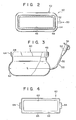
- Fig. 2 is a plan view of a water bag used in the device of Fig. 1;
- Fig. 3 is a front view of the water bag;
- Fig. 4 is a plan view of a fitting member used in the device of Fig. 1;
- Fig. 5 is a vertical sectional view of the fitting member;
- Fig. 6 is a front view of a clamp member used in the device of Fig. 1;
- Fig. 7 is a plan view of the clamp member;
- Fig. 8 is a side view of the clamp member;
- Fig. 9 is a perspective view of a probe fitted with the water bag; and
- Fig. 10 is a partial sectional view illustrating the way the water bag is exhausted.
- Figs. 1 to 10 show an ultrasonic probe device according to one embodiment of the present invention. As shown in Fig. 1, a
probe 20 has acase 22 substantially in the form of a rectangular parallelepiped, which hermetically contains therein a plurality of elements for transmitting and receiving ultrasonic waves. Thecase 22 has gently slopingshoulder faces 24, upperlateral faces 26, lowerlateral faces 28, and a bottom face or ultrasonic transmitting/receivingface 32. Acable 34 is led out from between the twoshoulder faces 24 which transmits electrical signals to the ultrasonic transmitting/receiving elements and sends the signals therefrom to a signal processing system (not shown). Astep portion 30 is formed between the upper and lowerlateral faces lateral faces 26 are longer than those of the lowerlateral faces 28. As the electrical signals are supplied to the ultrasonic transmitting/receiving elements, ultrasonic waves are transmitted from the ultrasonic transmitting/receivingface 32. When ultrasonic echoes are applied to the ultrasonic transmitting/receivingface 32, they are converted into electrical signals by the ultrasonic transmitting/receiving elements transmitted to the signal processing system through thecable 34. - A
water bag 40 has abaglike container portion 42 for containing water which serves as an acoustical medium, and anengaging portion 44 which is integrally formed with respect to thecontainer portion 42. Thecontainer portion 42 andengaging portion 44 are formed of a natural rubber, such as latex. Natural rubber is used since its acoustical characteristics resemble those of the human body, and since the water contained in such acontainer portion 42 produces less catoptric waves when ultrasonic waves are transmitted through thecontainer portion 42. The wall of thecontainer portion 42 is as thin as 0.1 to 0.2 mm, so that attenuation of the ultrasonic waves passing through the rubber sheet wall is minimized. The wall of theengaging portion 44 is relatively thick, being about 1 mm. Thus, thewater bag 40 is strong enough to be attached to theprobe 20, and watertightness between thewater bag 40 and theprobe 20 is ensured. - The peripheral edges of the
container portion 42, adjoining theengaging portion 44, are as long as or a little shorter than those of the lowerlateral faces 28 of theprobe 20. The peripheral edges of an opening 46 of theengaging portion 44 are as long as or a little shorter than those of the upperlateral faces 26 of theprobe 20. Theengaging portion 44 has a sealingportion 48 where it meets thecontainer portion 42, and whereby thewater bag 40 is constricted like a neck. Alternatively, thewhole water bag 40 may be formed with a uniform wall thickness. In this case, the shortage of the thickness of the engagingportion 44 must be filled by covering the engagingportion 44 with a ring about 1 mm thick, which is shaped in conformity with the engaging portion 44 (including the sealing portion 48). The material of this ring is not limited to natural rubber and may be selected from among any elastic materials, including synthetic rubber. - A
water feeder 50 is attached to the flank of thecontainer portion 42. Thiswater feeder 50 includes atube 52, attached to the flank of thecontainer portion 42, for communicating with the space inside thecontainer portion 42, and aconnector 54 attached to thetube 52. As shown in Fig. 10, theconnector 54 is so adapted as to be fitted with an injector 100, whereby water or air may be injected into or removed from thewater bag 40. - Referring now to Figs. 4 and 5, a
fitting member 60 may be described as follows. Thefitting member 60 is in the form of a shallow tray, and includes aperipheral press portion 62 and a rectangular engagingopening 68. A hooked retainingprojection 64 is formed on the central portion of each of the shorter sides of thepress member 62. Thepress portion 62 has a shape that matches thestep portion 30 of theprobe 20 and the engaging portion 44 (including the sealing portion 48) of thewater bag 40. Thus, thefitting member 60 may be fitted to theprobe 20 in such a way that thepress portion 62 engages the sealingportion 48 of thewater bag 40, as indicated by the broken lines of Fig. 5, after putting the engagingportion 44 of thewater bag 40 on the upper lateral faces 26 of theprobe 20, so that the sealingportion 48 can mate with thestep portion 30. - Referring now to Figs. 6, 7 and 8, a
clamp member 80 may be described as follows. Themain body 82 of theclamp member 80 has a shape which matches the shoulder faces 24 and upper lateral faces 26 of theprobe 20. Themain body 82 includes alateral plate 84 which serves to engage one of the upper lateral faces 26 of theprobe 20,shoulder plates 86 which serve to engage the shoulder faces 24 of theprobe 20, partiallateral plates 88 which are continuous with theindividual shoulder plates 86 and which face thelateral plate 84, andsupport portions 90 which are continuous with theindividual shoulder plates 86. Ahandle 92 is rockably supported at one end of each of thesupport portions 90 by means of apin 94. A retainingframe 96 is rockably attached to the substantially central portion of thehandle 92. As thehandles 92 rock in the directions ofarrows pins 94, the retaining frames 96 move up and down. When thehandles 92 rock in the direction ofarrow 4 and finally abut against theircorresponding support portions 90, the portions of the retaining frames 96 attached to thehandles 92 are located inside thepins 94, with respect to the facing direction of thesupport portions 90. Thefitting member 60 and theclamp member 80 must be composed of highly rigid materials to clamp the engagingportion 44 of thewater bag 40 between thesemembers members - Referring now to the disassembled and assembled views of Figs. 1 and 9, the operation of the
ultrasonic probe device 10 with the above-mentioned construction may be described as follows. First, thewater bag 40 is attached to theprobe 20. The engagingportion 44 of thewater bag 40 is put on the upper lateral faces 26 of theprobe 20, so that the sealingportion 48 of thewater bag 40 engages with thestep portion 30 of theprobe 20. Then, thefitting member 60 is put on thewater bag 40 so that thecontainer portion 42 is fitted into theopening 68, and thepress portion 62 engages with thestep portion 30 of theprobe 20 with the engagingportion 44 therebetween. Thereafter, theclamp member 80 is fitted to the shoulder faces 24 of theprobe 20. Thehandles 92 are rotated in the direction of thearrow 2 of Fig. 6 to lower the retaining frames 96. After the retaining frames 96 are caused to engage their correspondinghooked projections 64, thehandles 92 are rotated in the direction of thearrow 4 of Fig. 6, so as to abut against theircorresponding support portions 90. As a result, the retaining frames 96 are lifted up so that thefitting member 60 and theclamp member 80 may clamp thewater bag 40 against theprobe 20. At this time, the retaining frames 96 are located on the inner sides of theclamp member 80, as compared with theircorresponding pins 94, so that thehandles 92 are settled in this state. Thepress portion 62 of thefitting member 60 presses the sealingportion 48 of thewater bag 40 against thestep portion 30 of theprobe 20. In other words, the sealingportion 48 whose wall is somewhat thicker is held under pressure between thestep portion 30 and thepress portion 62. Thus, thewater bag 40 is hermetically attached to theprobe 20, and a sealed space is defined inside thewater bag 40. Then, the injector 100 is attached to theconnector 54, as shown in Fig. 10, and water is poured from the injector 100 into thewater bag 40 through thetube 52. In this case, it is to be desired that the water feed should be started after squeezing thecontainer portion 42 to remove as much air as possible. This should be done to avoid the production of air bubbles in the water poured into thewater bag 40. If air bubbles remain in the water in thewater bag 40, they may be sucked out by the injector 100, after turning the assembly in a manner such that the tube-connected portion of thecontainer portion 42 faces upward, as shown in Fig. 10; or, they may be removed by squeezing thecontainer portion 42. Water is further poured from the injector 100 into thewater bag 40, to fill up the same 40. Thereafter, the injector 100 is disengaged from theconnector 54, and the opening of theconnector 54 is closed by alid 56. Thewater bag 40 thus filled with the water is pressed against that part of the subject to be examined which requires diagnosis. Thus, the subject and theprobe 20 are acoustically coupled by means of the water in thewater bag 40 as an acoustic medium. When a signal is given to the ultrasonic transmitting/receiving elements in theprobe 20, ultrasonic waves from the ultrasonic transmitting/receivingface 32 of theprobe 20 are propagated through the water, are passed through the natural rubber sheet wall of thecontainer portion 42, and finally, reach the living body of the subject. Ultrasonic echoes reflected inside the living body pass through the sheet wall of thecontainer portion 42, and are propagated through the water to reach the ultrasonic transmitting/receivingface 32. Thereupon, the ultrasonic echoes are converted into electrical signals by the transmitting/receiving elements, and are transmitted to the signal processing system (not shown). In this case, reflection of the ultrasonic waves by the inside faces of thecontainer portion 42 of thewater bag 40 may be reduced to improve the efficiency of the ultrasonic diagnosis by making the sheet wall distance L (see Fig. 3) of thecontainer portion 42 longer than the ultrasonic transmitting region of the ultrasonic transmitting/receivingface 32. - It is to be understood that the present invention is not limited to the embodiment described above, since various changes and modifications may be effected therein by one skilled in the art, without departing from the scope or spirit of the invention. In particular, the acoustical medium is not limited to water, and may be suitably selected, according to the kind of subject to be examined. Also, the present invention may be applied to technologies other than ultrasonic diagnosis. In the above embodiment, the
fitting member 60 andclamp member 80 are provided separately. Alternatively, however, theclamp member 80 may be rockably mounted on thefitting member 60, at the position of one of the hookedprojections 64.
Claims (7)
characterized in that the case has a probe engaging portion (30) on the lateral faces (26, 28) thereof; and characterized by comprising
Applications Claiming Priority (2)
| Application Number | Priority Date | Filing Date | Title |
|---|---|---|---|
| JP43575/83U | 1983-03-25 | ||
| JP1983043575U JPS59147508U (en) | 1983-03-25 | 1983-03-25 | Ultrasonic probe adapter |
Publications (3)
| Publication Number | Publication Date |
|---|---|
| EP0120410A2 true EP0120410A2 (en) | 1984-10-03 |
| EP0120410A3 EP0120410A3 (en) | 1986-01-22 |
| EP0120410B1 EP0120410B1 (en) | 1989-11-08 |
Family
ID=12667547
Family Applications (1)
| Application Number | Title | Priority Date | Filing Date |
|---|---|---|---|
| EP84102798A Expired EP0120410B1 (en) | 1983-03-25 | 1984-03-14 | Ultrasonic probe device |
Country Status (5)
| Country | Link |
|---|---|
| US (1) | US4688578A (en) |
| EP (1) | EP0120410B1 (en) |
| JP (1) | JPS59147508U (en) |
| KR (1) | KR860002847Y1 (en) |
| DE (1) | DE3480441D1 (en) |
Cited By (7)
| Publication number | Priority date | Publication date | Assignee | Title |
|---|---|---|---|---|
| EP0483238A1 (en) * | 1989-07-26 | 1992-05-06 | Boston Scient Corp | Tip filled ultrasound catheter. |
| FR2689760A1 (en) * | 1992-04-10 | 1993-10-15 | Technomed Int Sa | Device for generating pressure waves with a very flexible flat membrane and treatment apparatus comprising such a device. |
| WO2000040153A1 (en) * | 1998-12-30 | 2000-07-13 | G.E. Vingmed Ultrasound A/S | Damping cushion for ultrasound probes |
| WO2004037091A1 (en) * | 2002-10-28 | 2004-05-06 | Ulrich Baumann | Pressure measuring unit for ultrasound measuring devices |
| WO2008018054A3 (en) * | 2006-08-08 | 2008-09-25 | Keter Medical Ltd | Imaging system |
| WO2019106535A1 (en) * | 2017-11-28 | 2019-06-06 | Baumann, Vincent | Pressure measurement device for measuring pressure and/or for measuring elasticity of a vein or an organ and for combination with an ultrasonic measurement unit, pressure measurement system, and method |
| US20210361259A1 (en) * | 2019-04-23 | 2021-11-25 | Decision Sciences Medical Company, LLC | Semi-rigid acoustic coupling articles for ultrasound diagnostic and treatment applications |
Families Citing this family (73)
| Publication number | Priority date | Publication date | Assignee | Title |
|---|---|---|---|---|
| JPS61288840A (en) * | 1985-06-14 | 1986-12-19 | 古田 直樹 | Applicator for ultrasonic probe |
| JPS61288841A (en) * | 1985-06-14 | 1986-12-19 | 古田 直樹 | Applicator for ultrasonic probe |
| JPS61288842A (en) * | 1985-06-14 | 1986-12-19 | 古田 直樹 | Applicator for ultrasonic probe |
| JPS62328A (en) * | 1985-06-25 | 1987-01-06 | 古田 直樹 | Applicator for ultrasonic probe |
| US4867169A (en) * | 1986-07-29 | 1989-09-19 | Kaoru Machida | Attachment attached to ultrasound probe for clinical application |
| WO1990001902A1 (en) * | 1988-08-30 | 1990-03-08 | Fujitsu Limited | Acoustic coupler |
| US5076279A (en) * | 1990-07-17 | 1991-12-31 | Acuson Corporation | Needle guide for assembly upon an ultrasound imaging transducer |
| AU766783B2 (en) * | 1997-08-19 | 2003-10-23 | Philipp Lang | Ultrasonic transmission films and devices, particularly for hygienic transducer surfaces |
| US7510536B2 (en) * | 1999-09-17 | 2009-03-31 | University Of Washington | Ultrasound guided high intensity focused ultrasound treatment of nerves |
| US7520856B2 (en) * | 1999-09-17 | 2009-04-21 | University Of Washington | Image guided high intensity focused ultrasound device for therapy in obstetrics and gynecology |
| AU2619301A (en) | 1999-10-25 | 2001-06-06 | Therus Corporation | Use of focused ultrasound for vascular sealing |
| US6626855B1 (en) | 1999-11-26 | 2003-09-30 | Therus Corpoation | Controlled high efficiency lesion formation using high intensity ultrasound |
| US8206299B2 (en) * | 2003-12-16 | 2012-06-26 | University Of Washington | Image guided high intensity focused ultrasound treatment of nerves |
| US9066679B2 (en) | 2004-08-31 | 2015-06-30 | University Of Washington | Ultrasonic technique for assessing wall vibrations in stenosed blood vessels |
| MX2007003044A (en) * | 2004-09-16 | 2007-08-02 | Univ Washington | Acoustic coupler using an independent water pillow with circulation for cooling a transducer. |
| CN101106944B (en) * | 2005-01-26 | 2011-01-05 | 株式会社日立医药 | Pressing member, ultrasonic probe and ultrasonic diagnosing device |
| WO2007021958A2 (en) * | 2005-08-12 | 2007-02-22 | University Of Washington | Method and apparatus for preparing organs and tissues for laparoscopic surgery |
| US8784336B2 (en) * | 2005-08-24 | 2014-07-22 | C. R. Bard, Inc. | Stylet apparatuses and methods of manufacture |
| US8414494B2 (en) * | 2005-09-16 | 2013-04-09 | University Of Washington | Thin-profile therapeutic ultrasound applicators |
| US8016757B2 (en) * | 2005-09-30 | 2011-09-13 | University Of Washington | Non-invasive temperature estimation technique for HIFU therapy monitoring using backscattered ultrasound |
| US8167805B2 (en) | 2005-10-20 | 2012-05-01 | Kona Medical, Inc. | Systems and methods for ultrasound applicator station keeping |
| US8388546B2 (en) | 2006-10-23 | 2013-03-05 | Bard Access Systems, Inc. | Method of locating the tip of a central venous catheter |
| US7794407B2 (en) | 2006-10-23 | 2010-09-14 | Bard Access Systems, Inc. | Method of locating the tip of a central venous catheter |
| US10524691B2 (en) | 2007-11-26 | 2020-01-07 | C. R. Bard, Inc. | Needle assembly including an aligned magnetic element |
| US9636031B2 (en) * | 2007-11-26 | 2017-05-02 | C.R. Bard, Inc. | Stylets for use with apparatus for intravascular placement of a catheter |
| US8781555B2 (en) | 2007-11-26 | 2014-07-15 | C. R. Bard, Inc. | System for placement of a catheter including a signal-generating stylet |
| US9521961B2 (en) | 2007-11-26 | 2016-12-20 | C. R. Bard, Inc. | Systems and methods for guiding a medical instrument |
| US10751509B2 (en) | 2007-11-26 | 2020-08-25 | C. R. Bard, Inc. | Iconic representations for guidance of an indwelling medical device |
| ES2651898T3 (en) | 2007-11-26 | 2018-01-30 | C.R. Bard Inc. | Integrated system for intravascular catheter placement |
| US8849382B2 (en) | 2007-11-26 | 2014-09-30 | C. R. Bard, Inc. | Apparatus and display methods relating to intravascular placement of a catheter |
| US10449330B2 (en) | 2007-11-26 | 2019-10-22 | C. R. Bard, Inc. | Magnetic element-equipped needle assemblies |
| US9649048B2 (en) | 2007-11-26 | 2017-05-16 | C. R. Bard, Inc. | Systems and methods for breaching a sterile field for intravascular placement of a catheter |
| US8478382B2 (en) | 2008-02-11 | 2013-07-02 | C. R. Bard, Inc. | Systems and methods for positioning a catheter |
| JP4374470B1 (en) * | 2008-07-22 | 2009-12-02 | 国立大学法人 東京大学 | Acoustic matching device for knee for ultrasonic probe |
| ES2525525T3 (en) | 2008-08-22 | 2014-12-26 | C.R. Bard, Inc. | Catheter assembly that includes ECG and magnetic sensor assemblies |
| US8437833B2 (en) | 2008-10-07 | 2013-05-07 | Bard Access Systems, Inc. | Percutaneous magnetic gastrostomy |
| US20100160781A1 (en) * | 2008-12-09 | 2010-06-24 | University Of Washington | Doppler and image guided device for negative feedback phased array hifu treatment of vascularized lesions |
| US9445734B2 (en) * | 2009-06-12 | 2016-09-20 | Bard Access Systems, Inc. | Devices and methods for endovascular electrography |
| ES2745861T3 (en) * | 2009-06-12 | 2020-03-03 | Bard Access Systems Inc | Apparatus, computer-aided data-processing algorithm, and computer storage medium for positioning an endovascular device in or near the heart |
| US9532724B2 (en) | 2009-06-12 | 2017-01-03 | Bard Access Systems, Inc. | Apparatus and method for catheter navigation using endovascular energy mapping |
| WO2011044421A1 (en) | 2009-10-08 | 2011-04-14 | C. R. Bard, Inc. | Spacers for use with an ultrasound probe |
| US10639008B2 (en) | 2009-10-08 | 2020-05-05 | C. R. Bard, Inc. | Support and cover structures for an ultrasound probe head |
| US9174065B2 (en) | 2009-10-12 | 2015-11-03 | Kona Medical, Inc. | Energetic modulation of nerves |
| US8986211B2 (en) | 2009-10-12 | 2015-03-24 | Kona Medical, Inc. | Energetic modulation of nerves |
| US8986231B2 (en) | 2009-10-12 | 2015-03-24 | Kona Medical, Inc. | Energetic modulation of nerves |
| US9119951B2 (en) | 2009-10-12 | 2015-09-01 | Kona Medical, Inc. | Energetic modulation of nerves |
| US20160059044A1 (en) | 2009-10-12 | 2016-03-03 | Kona Medical, Inc. | Energy delivery to intraparenchymal regions of the kidney to treat hypertension |
| US8517962B2 (en) | 2009-10-12 | 2013-08-27 | Kona Medical, Inc. | Energetic modulation of nerves |
| US8295912B2 (en) | 2009-10-12 | 2012-10-23 | Kona Medical, Inc. | Method and system to inhibit a function of a nerve traveling with an artery |
| US20110092880A1 (en) | 2009-10-12 | 2011-04-21 | Michael Gertner | Energetic modulation of nerves |
| US20110118600A1 (en) | 2009-11-16 | 2011-05-19 | Michael Gertner | External Autonomic Modulation |
| US8469904B2 (en) | 2009-10-12 | 2013-06-25 | Kona Medical, Inc. | Energetic modulation of nerves |
| CN102821679B (en) | 2010-02-02 | 2016-04-27 | C·R·巴德股份有限公司 | For the apparatus and method that catheter navigation and end are located |
| ES2778041T3 (en) | 2010-05-28 | 2020-08-07 | Bard Inc C R | Apparatus for use with needle insertion guidance system |
| EP2912999B1 (en) | 2010-05-28 | 2022-06-29 | C. R. Bard, Inc. | Apparatus for use with needle insertion guidance system |
| WO2012024577A2 (en) | 2010-08-20 | 2012-02-23 | C.R. Bard, Inc. | Reconfirmation of ecg-assisted catheter tip placement |
| US8801693B2 (en) | 2010-10-29 | 2014-08-12 | C. R. Bard, Inc. | Bioimpedance-assisted placement of a medical device |
| AU2012278809B2 (en) | 2011-07-06 | 2016-09-29 | C.R. Bard, Inc. | Needle length determination and calibration for insertion guidance system |
| USD699359S1 (en) | 2011-08-09 | 2014-02-11 | C. R. Bard, Inc. | Ultrasound probe head |
| USD724745S1 (en) | 2011-08-09 | 2015-03-17 | C. R. Bard, Inc. | Cap for an ultrasound probe |
| US11275056B2 (en) | 2011-10-18 | 2022-03-15 | Cidra Corporate Services Inc. | Method and apparatus for providing real time air measurement applications in wet concrete using dual frequency techniques |
| US10156547B2 (en) | 2011-10-18 | 2018-12-18 | Cidra Corporate Services Inc. | Method and apparatus for providing real time air measurement applications in wet concrete |
| US9211107B2 (en) | 2011-11-07 | 2015-12-15 | C. R. Bard, Inc. | Ruggedized ultrasound hydrogel insert |
| EP2861153A4 (en) | 2012-06-15 | 2016-10-19 | Bard Inc C R | Apparatus and methods for detection of a removable cap on an ultrasound probe |
| CN105979868B (en) | 2014-02-06 | 2020-03-10 | C·R·巴德股份有限公司 | Systems and methods for guidance and placement of intravascular devices |
| USD732672S1 (en) * | 2014-02-16 | 2015-06-23 | Zetroz, Inc. | Ultrasound applicator |
| USD746994S1 (en) * | 2014-02-17 | 2016-01-05 | Zetroz, Inc. | Ultrasound applicator coupling bandage assembly |
| US10925579B2 (en) | 2014-11-05 | 2021-02-23 | Otsuka Medical Devices Co., Ltd. | Systems and methods for real-time tracking of a target tissue using imaging before and during therapy delivery |
| US10973584B2 (en) | 2015-01-19 | 2021-04-13 | Bard Access Systems, Inc. | Device and method for vascular access |
| US10349890B2 (en) | 2015-06-26 | 2019-07-16 | C. R. Bard, Inc. | Connector interface for ECG-based catheter positioning system |
| US11000207B2 (en) | 2016-01-29 | 2021-05-11 | C. R. Bard, Inc. | Multiple coil system for tracking a medical device |
| WO2020081373A1 (en) | 2018-10-16 | 2020-04-23 | Bard Access Systems, Inc. | Safety-equipped connection systems and methods thereof for establishing electrical connections |
| TWI686179B (en) * | 2018-10-25 | 2020-03-01 | 佳世達科技股份有限公司 | Ultrasonic probe apparatus and bag device thereof |
Citations (5)
| Publication number | Priority date | Publication date | Assignee | Title |
|---|---|---|---|---|
| FR2318613A1 (en) * | 1975-07-21 | 1977-02-18 | Stanford Research Inst | COUPLING AND CLOSING DEVICE FOR ULTRASONIC TRANSMISSION BETWEEN A LIQUID AND A SAMPLE |
| US4154231A (en) * | 1977-11-23 | 1979-05-15 | Russell Robert B | System for non-invasive cardiac diagnosis |
| US4181120A (en) * | 1976-04-23 | 1980-01-01 | Tokyo Shibaura Electric Co., Ltd. | Vessel for ultrasonic scanner |
| EP0059785A1 (en) * | 1981-03-10 | 1982-09-15 | Siemens Aktiengesellschaft | Ultrasound applicator |
| DE3337842A1 (en) * | 1982-10-26 | 1984-04-26 | Storz Instrument Co., St. Louis, Mo. | Ultrasonic probe |
Family Cites Families (6)
| Publication number | Priority date | Publication date | Assignee | Title |
|---|---|---|---|---|
| JPS53107190A (en) * | 1977-03-01 | 1978-09-18 | Tokyo Shibaura Electric Co | Electron scan ultrasonic diagnosing device |
| US4185502A (en) * | 1977-10-11 | 1980-01-29 | Ralph Frank | Transducer coupling apparatus |
| US4282880A (en) * | 1980-03-12 | 1981-08-11 | Technicare Corporation | Water circulation and maintenance system for an ultrasound mammary scanning apparatus |
| JPS58160447A (en) * | 1982-03-17 | 1983-09-22 | 松下電器産業株式会社 | Toilet apparatus |
| JPS5930213U (en) * | 1982-08-17 | 1984-02-24 | 株式会社東芝 | Puncture type ultrasound probe adapter |
| US4469106A (en) * | 1982-09-02 | 1984-09-04 | Advanced Technology Laboratories, Inc. | Needle guide for use with medical ultrasonic scanning apparatus |
-
1983
- 1983-03-25 JP JP1983043575U patent/JPS59147508U/en active Granted
-
1984
- 1984-03-14 EP EP84102798A patent/EP0120410B1/en not_active Expired
- 1984-03-14 DE DE8484102798T patent/DE3480441D1/en not_active Expired
- 1984-03-16 KR KR2019840002292U patent/KR860002847Y1/en not_active IP Right Cessation
- 1984-03-16 US US06/590,287 patent/US4688578A/en not_active Expired - Fee Related
Patent Citations (5)
| Publication number | Priority date | Publication date | Assignee | Title |
|---|---|---|---|---|
| FR2318613A1 (en) * | 1975-07-21 | 1977-02-18 | Stanford Research Inst | COUPLING AND CLOSING DEVICE FOR ULTRASONIC TRANSMISSION BETWEEN A LIQUID AND A SAMPLE |
| US4181120A (en) * | 1976-04-23 | 1980-01-01 | Tokyo Shibaura Electric Co., Ltd. | Vessel for ultrasonic scanner |
| US4154231A (en) * | 1977-11-23 | 1979-05-15 | Russell Robert B | System for non-invasive cardiac diagnosis |
| EP0059785A1 (en) * | 1981-03-10 | 1982-09-15 | Siemens Aktiengesellschaft | Ultrasound applicator |
| DE3337842A1 (en) * | 1982-10-26 | 1984-04-26 | Storz Instrument Co., St. Louis, Mo. | Ultrasonic probe |
Cited By (12)
| Publication number | Priority date | Publication date | Assignee | Title |
|---|---|---|---|---|
| EP0483238A1 (en) * | 1989-07-26 | 1992-05-06 | Boston Scient Corp | Tip filled ultrasound catheter. |
| EP0483238A4 (en) * | 1989-07-26 | 1992-08-19 | Boston Scientific Corporation | Tip filled ultrasound catheter |
| FR2689760A1 (en) * | 1992-04-10 | 1993-10-15 | Technomed Int Sa | Device for generating pressure waves with a very flexible flat membrane and treatment apparatus comprising such a device. |
| WO1993020758A1 (en) * | 1992-04-10 | 1993-10-28 | Technomed International | Pressure wave generating device with a highly flexible flat membrane and treatment apparatus comprising such device |
| WO2000040153A1 (en) * | 1998-12-30 | 2000-07-13 | G.E. Vingmed Ultrasound A/S | Damping cushion for ultrasound probes |
| US6210336B1 (en) | 1998-12-30 | 2001-04-03 | G.E. Vingmed Ultrasound A/S | Damping cushion for ultrasound probes |
| WO2004037091A1 (en) * | 2002-10-28 | 2004-05-06 | Ulrich Baumann | Pressure measuring unit for ultrasound measuring devices |
| EP1415596A1 (en) * | 2002-10-28 | 2004-05-06 | Ulrich André Baumann | Pressure measuring device for an ultrasonic measuring apparatus |
| WO2008018054A3 (en) * | 2006-08-08 | 2008-09-25 | Keter Medical Ltd | Imaging system |
| WO2019106535A1 (en) * | 2017-11-28 | 2019-06-06 | Baumann, Vincent | Pressure measurement device for measuring pressure and/or for measuring elasticity of a vein or an organ and for combination with an ultrasonic measurement unit, pressure measurement system, and method |
| US11957512B2 (en) | 2017-11-28 | 2024-04-16 | Compremium Ag | Pressure measurement device for measuring pressure and/or for measuring elasticity of a vein or an organ and for combination with an ultrasound measurement unit, pressure measurement system, and method |
| US20210361259A1 (en) * | 2019-04-23 | 2021-11-25 | Decision Sciences Medical Company, LLC | Semi-rigid acoustic coupling articles for ultrasound diagnostic and treatment applications |
Also Published As
| Publication number | Publication date |
|---|---|
| KR850007945U (en) | 1985-10-26 |
| EP0120410A3 (en) | 1986-01-22 |
| DE3480441D1 (en) | 1989-12-14 |
| KR860002847Y1 (en) | 1986-10-20 |
| EP0120410B1 (en) | 1989-11-08 |
| JPH039685Y2 (en) | 1991-03-11 |
| US4688578A (en) | 1987-08-25 |
| JPS59147508U (en) | 1984-10-02 |
Similar Documents
| Publication | Publication Date | Title |
|---|---|---|
| US4688578A (en) | Ultrasonic probe device | |
| EP0973448B1 (en) | Coupling pad for medical ultrasound devices | |
| US20040254464A1 (en) | Apparatus and method for three dimensional ultrasound breast imaging | |
| JPH0530727Y2 (en) | ||
| EP0276289B1 (en) | An ultrasonic investigation apparatus | |
| EP0527651A1 (en) | Acoustic standoff for ultrasound scanhead | |
| CN216916967U (en) | Pathological specimen storage device | |
| JP3866485B2 (en) | Ultrasonic probe connector cover | |
| JPH0257421B2 (en) | ||
| JPS6111024A (en) | Protective cover of water tank for medical ultrasonic diagnostic apparatus | |
| CN220738673U (en) | Ultrasonic image probe cleaning device | |
| JPS6255623B2 (en) | ||
| JPS6323503B2 (en) | ||
| CN210019408U (en) | Novel ultrasonic isolation sound-transmitting membrane | |
| JPS6061010U (en) | ultrasonic probe | |
| JPS59111744A (en) | Ultrasonic probe and adaptor thereof | |
| CN216655582U (en) | Ultrasonic department color ultrasound probe disinfection device | |
| JPH05285133A (en) | Waterproof structure of ultrasonic probe and waterproof cover of probe concerned | |
| CN211512111U (en) | Full-soaking type endoscope cleaning machine | |
| JPH0229929Y2 (en) | ||
| JP4497679B2 (en) | Ultrasonic vibrator and ultrasonic processing apparatus | |
| JPS6232003Y2 (en) | ||
| JPS5861737A (en) | Water immersion type ultrasonic diagnostic apparatus | |
| JPS6248305U (en) | ||
| SU1242125A1 (en) | Method of examining abdominal cavity |
Legal Events
| Date | Code | Title | Description |
|---|---|---|---|
| PUAI | Public reference made under article 153(3) epc to a published international application that has entered the european phase |
Free format text: ORIGINAL CODE: 0009012 |
|
| 17P | Request for examination filed |
Effective date: 19840411 |
|
| AK | Designated contracting states |
Designated state(s): DE FR GB NL |
|
| PUAL | Search report despatched |
Free format text: ORIGINAL CODE: 0009013 |
|
| AK | Designated contracting states |
Designated state(s): DE FR GB NL |
|
| 17Q | First examination report despatched |
Effective date: 19870810 |
|
| GRAA | (expected) grant |
Free format text: ORIGINAL CODE: 0009210 |
|
| AK | Designated contracting states |
Kind code of ref document: B1 Designated state(s): DE FR GB NL |
|
| REF | Corresponds to: |
Ref document number: 3480441 Country of ref document: DE Date of ref document: 19891214 |
|
| ET | Fr: translation filed | ||
| PLBE | No opposition filed within time limit |
Free format text: ORIGINAL CODE: 0009261 |
|
| STAA | Information on the status of an ep patent application or granted ep patent |
Free format text: STATUS: NO OPPOSITION FILED WITHIN TIME LIMIT |
|
| 26N | No opposition filed | ||
| PGFP | Annual fee paid to national office [announced via postgrant information from national office to epo] |
Ref country code: GB Payment date: 19950306 Year of fee payment: 12 |
|
| PGFP | Annual fee paid to national office [announced via postgrant information from national office to epo] |
Ref country code: FR Payment date: 19950309 Year of fee payment: 12 Ref country code: DE Payment date: 19950309 Year of fee payment: 12 |
|
| PGFP | Annual fee paid to national office [announced via postgrant information from national office to epo] |
Ref country code: NL Payment date: 19950331 Year of fee payment: 12 |
|
| PG25 | Lapsed in a contracting state [announced via postgrant information from national office to epo] |
Ref country code: GB Effective date: 19960314 |
|
| PG25 | Lapsed in a contracting state [announced via postgrant information from national office to epo] |
Ref country code: NL Effective date: 19961001 |
|
| GBPC | Gb: european patent ceased through non-payment of renewal fee |
Effective date: 19960314 |
|
| PG25 | Lapsed in a contracting state [announced via postgrant information from national office to epo] |
Ref country code: FR Effective date: 19961129 |
|
| NLV4 | Nl: lapsed or anulled due to non-payment of the annual fee |
Effective date: 19961001 |
|
| PG25 | Lapsed in a contracting state [announced via postgrant information from national office to epo] |
Ref country code: DE Effective date: 19961203 |
|
| REG | Reference to a national code |
Ref country code: FR Ref legal event code: ST |