EP0120715A2 - Optical measuring cells - Google Patents
Optical measuring cells Download PDFInfo
- Publication number
- EP0120715A2 EP0120715A2 EP19840302149 EP84302149A EP0120715A2 EP 0120715 A2 EP0120715 A2 EP 0120715A2 EP 19840302149 EP19840302149 EP 19840302149 EP 84302149 A EP84302149 A EP 84302149A EP 0120715 A2 EP0120715 A2 EP 0120715A2
- Authority
- EP
- European Patent Office
- Prior art keywords
- base member
- channel
- optical measuring
- fluid
- measuring cell
- Prior art date
- Legal status (The legal status is an assumption and is not a legal conclusion. Google has not performed a legal analysis and makes no representation as to the accuracy of the status listed.)
- Withdrawn
Links
Images
Classifications
-
- G—PHYSICS
- G01—MEASURING; TESTING
- G01N—INVESTIGATING OR ANALYSING MATERIALS BY DETERMINING THEIR CHEMICAL OR PHYSICAL PROPERTIES
- G01N21/00—Investigating or analysing materials by the use of optical means, i.e. using sub-millimetre waves, infrared, visible or ultraviolet light
- G01N21/01—Arrangements or apparatus for facilitating the optical investigation
- G01N21/03—Cuvette constructions
- G01N2021/0325—Cells for testing reactions, e.g. containing reagents
-
- G—PHYSICS
- G01—MEASURING; TESTING
- G01N—INVESTIGATING OR ANALYSING MATERIALS BY DETERMINING THEIR CHEMICAL OR PHYSICAL PROPERTIES
- G01N21/00—Investigating or analysing materials by the use of optical means, i.e. using sub-millimetre waves, infrared, visible or ultraviolet light
- G01N21/01—Arrangements or apparatus for facilitating the optical investigation
- G01N21/03—Cuvette constructions
- G01N2021/0346—Capillary cells; Microcells
Definitions
- This invention relates to cells for use in the analysis of small quantities of fluid by means of light passing through the fluid.
- a common medical diagnostic test is the determination of a substance in a body fluid, e.g. sugars, proteins, hormones or haemoglobin in urine or blood.
- an indicator "stick" consisting of a long thin carrier of paper or other suitable material impregnated with a reagent is dipped in a sample of fluid. The stick is then washed and the colour of the stick indicates the level of the substance to be determined. The colour may be determined by comparing the stick with a calibrated colour chart or alternatively machines are available for determining the colour opto-electronically. For example, a small portable machine is available which has a slot into which the indicator stick may be inserted, a light source directed at the stick and a light sensor and associated electronic circuit and indicator for determining the amount of light of a predetermined wavelength reflected from the stick.
- a cuvette containing a reagent is filled with blood and the optical density of the resulting mixture is measured by shining light through the filled cuvette and measuring the proportion of light transmitted.
- an optical measuring cell comprising an elongate base member having a channel formed in one face thereof and a transparent cover fixed to the base member over the channel over at least part of the length of the base member, the channel being di- mensioned such that in use fluid to be tested may be drawn by capillary action into the channel and the base member being reflective so that light passing through the cover and fluid is reflected to pass again through the fluid and cover.
- a method of optically analysing a fluid which comprises placing an optical measuring cell as defined above in the fluid whereby the fluid is drawn by capillary action into the channel, passing light through the transparent cover into the channel and analysing the light reflected back through the transparent cover.
- a measuring cell according to the invention has the advantages that it is easy and economical to produce and the use of the reflection arrangement enables an existing measurement apparatus, such as the portable apparatus referred to above, to be used. Indeed, the cell may be made to have virtually the same dimensions as the conventional indicator stick and it is therefore readily acceptable to technicians familiar with the conventional indicator stick.
- the transparent cover extends over only a part of the length of the base member; this limits the amount of channel which is filled with the fluid to be tested thereby reducing the consumption of sample.
- the cell may contain a measured amount of one or more reagents, preferably in solid, e.g. freeze dried, form.
- the limited length of the transparent cover may be of advantage in this connection in that it accurately determines the amount of sample brought into contact with the reagents.
- the cell according to the invention comprises a tube of substantially uniform rectangular cross-section of which one side is transparent and of which the opposing side is provided with a reflective surface.
- a tube may, for example, be formed as a one-piece unit or by assembling a number of, e.g. two, units.
- the cell will be formed from plastics material in which case it is most desirable to mould or extrude a base member from an opaque reflective plastics material, e.g. white ABS and then to fix a transparent cover slip thereto over at least a portion of the channel formed by the base member, for example by solvent or heat welding.
- the cover slip may, for example, be formed from clear polycarbonate.
- the cell may be formed as a one-piece unit by extruding a rectangular tube of clear plastics material and subsequently applying reflective material e.g. paint or plastics material as appropriate, for example to the back of the base member. It may be preferred not to use paint in the channel if there is thought to be a risk of contaminating a sample.
- reflective material e.g. paint or plastics material as appropriate, for example to the back of the base member. It may be preferred not to use paint in the channel if there is thought to be a risk of contaminating a sample.
- the measuring cell comprises a base member 1 of rectangular cross-section having a channel 2.
- the base member 1 is preferably formed from opaque reflective material, e.g. white ABS plastics material.
- the base member 1 may be formed from non-reflective material and a reflective surface, e.g. white reflective paint or plastics material, may then be applied to the channel 2 or, if the base member 1 is formed from a transparent material, to the back surface 3 of base member 1.
- a diffuse reflector is preferred to avoid errors which might be caused by misalignment in the electro-optical measurement apparatus were a shiny reflector used.
- the base member 1 has fixed at one end over a portion of the channel 2 a cover slip 4 of transparent material, e.g. polycarbonate.
- the channel 2 and the cover slip 4 define between them a sample measuring area 5 into which, in use, fluid is drawn by capillary action
- the base member 1 incorporating the channel 2 and the cover slip 4 are thus dimensioned to permit such capillary forces to operate whilst still allowing the cell to be easily handled. It will be appreciated that the capillary forces will depend on the fluid to be tested.
- suitable dimensions for the base member 1 are, for example about 4 x 100 x 1.00 mm with a channel 2 depth of the order of 0.1 mm.
- the cover slip 4 may, for example, have dimensions of the order of 4 x 10 x 0.1 mm, although it could easily be considerably thicker, e.g. if required for strength or rigidity.
- One or more reagents may be provided in the channel 2, conveniently by printing, e.g. screenprinting, the channel before the cover slip is affixed thereto.
- the cell In use the cell is placed with the end carrying the cover slip 4 in the fluid to be tested The fluid is drawn-up by capillary forces into the sample measuring area 5. This fluid in the sample measuring area 5 is then subjected to optical analysis by passing' a beam of light into the sample measuring area 5 through the transparent cover slip 4 and analysing the light reflected back from the reflective surface provided by or on base member 1. Production and analysis of the light beam may be carried out by conventional methods well known in the art.
- the cell will be adapted for use in a conventional optical density measuring device.
- the cell according to the invention is of particular use in the determination of haemoglobin concentration in blood samples.
- a special advantage of the cells according to the invention is that they are not only extremely easy to use but are also relatively cheap to produce. Further, only a small quantity of sample, e.g. 4 microlitres, is required and this is easily available from a pricked finger. Typical prior art measuring systems may require about 20-30 microlitres of sample.
- the amount of sample drawn up may be defined by the length of the cover slip 4 which may be of value when the sample is to react with reagents in the channel 2.
- a further advantage is that the cell according to the invention can be used to measure the optical density of whole blood as it provides a relatively thin layer. Prior art techniques have required blood to be diluted or lysed for optical density measurement.
Abstract
An optical measuring cell comprises an elongate base member 1 having a channel formed in one face thereof and a transparent cover 4 fixed to the base member over the channel over at least part of the length of the base member, the channel being dimensioned such that in use fluid to be tested may be drawn by capillary action into the channel. The base member is reflective so that light passing through the cover and fluid is reflected to pass again through the fluid and cover. The cell may be used for the determination of the concentration of haemoglobin in undiluted blood samples.
Description
- This invention relates to cells for use in the analysis of small quantities of fluid by means of light passing through the fluid.
- A common medical diagnostic test is the determination of a substance in a body fluid, e.g. sugars, proteins, hormones or haemoglobin in urine or blood. In one common technique an indicator "stick" consisting of a long thin carrier of paper or other suitable material impregnated with a reagent is dipped in a sample of fluid. The stick is then washed and the colour of the stick indicates the level of the substance to be determined. The colour may be determined by comparing the stick with a calibrated colour chart or alternatively machines are available for determining the colour opto-electronically. For example, a small portable machine is available which has a slot into which the indicator stick may be inserted, a light source directed at the stick and a light sensor and associated electronic circuit and indicator for determining the amount of light of a predetermined wavelength reflected from the stick.
- In another measurement method, suitable for determining haemoglobin, a cuvette containing a reagent is filled with blood and the optical density of the resulting mixture is measured by shining light through the filled cuvette and measuring the proportion of light transmitted.
- According to the present invention there is provided an optical measuring cell comprising an elongate base member having a channel formed in one face thereof and a transparent cover fixed to the base member over the channel over at least part of the length of the base member, the channel being di- mensioned such that in use fluid to be tested may be drawn by capillary action into the channel and the base member being reflective so that light passing through the cover and fluid is reflected to pass again through the fluid and cover.
- According to a further feature of the invention there is provided a method of optically analysing a fluid which comprises placing an optical measuring cell as defined above in the fluid whereby the fluid is drawn by capillary action into the channel, passing light through the transparent cover into the channel and analysing the light reflected back through the transparent cover.
- A measuring cell according to the invention has the advantages that it is easy and economical to produce and the use of the reflection arrangement enables an existing measurement apparatus, such as the portable apparatus referred to above, to be used. Indeed, the cell may be made to have virtually the same dimensions as the conventional indicator stick and it is therefore readily acceptable to technicians familiar with the conventional indicator stick.
- Preferably, the transparent cover extends over only a part of the length of the base member; this limits the amount of channel which is filled with the fluid to be tested thereby reducing the consumption of sample.
- If desired, the cell may contain a measured amount of one or more reagents, preferably in solid, e.g. freeze dried, form. The limited length of the transparent cover may be of advantage in this connection in that it accurately determines the amount of sample brought into contact with the reagents.
- Advantageously the cell according to the invention comprises a tube of substantially uniform rectangular cross-section of which one side is transparent and of which the opposing side is provided with a reflective surface. Such a tube may, for example, be formed as a one-piece unit or by assembling a number of, e.g. two, units. Preferably the cell will be formed from plastics material in which case it is most desirable to mould or extrude a base member from an opaque reflective plastics material, e.g. white ABS and then to fix a transparent cover slip thereto over at least a portion of the channel formed by the base member, for example by solvent or heat welding. The cover slip may, for example, be formed from clear polycarbonate.
- Alternatively, however, the cell may be formed as a one-piece unit by extruding a rectangular tube of clear plastics material and subsequently applying reflective material e.g. paint or plastics material as appropriate, for example to the back of the base member. It may be preferred not to use paint in the channel if there is thought to be a risk of contaminating a sample.
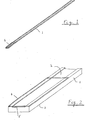
- An exemplary embodiment of the invention will be illustrated with reference to the accompanying drawings, wherein
- Fig. 1 shows a measuring cell according to the invention and
- Fig. 2 shows an enlargement of one end of the cell of Fig. 1.
- Referring to the drawings, the measuring cell comprises a base member 1 of rectangular cross-section having a
channel 2. The base member 1 is preferably formed from opaque reflective material, e.g. white ABS plastics material. Alternatively the base member 1 may be formed from non-reflective material and a reflective surface, e.g. white reflective paint or plastics material, may then be applied to thechannel 2 or, if the base member 1 is formed from a transparent material, to theback surface 3 of base member 1. A diffuse reflector is preferred to avoid errors which might be caused by misalignment in the electro-optical measurement apparatus were a shiny reflector used. - The base member 1 has fixed at one end over a portion of the channel 2 a
cover slip 4 of transparent material, e.g. polycarbonate. Thechannel 2 and thecover slip 4 define between them asample measuring area 5 into which, in use, fluid is drawn by capillary action The base member 1 incorporating thechannel 2 and thecover slip 4 are thus dimensioned to permit such capillary forces to operate whilst still allowing the cell to be easily handled. It will be appreciated that the capillary forces will depend on the fluid to be tested. For aqueous fluids suitable dimensions for the base member 1 are, for example about 4 x 100 x 1.00 mm with achannel 2 depth of the order of 0.1 mm. Thecover slip 4 may, for example, have dimensions of the order of 4 x 10 x 0.1 mm, although it could easily be considerably thicker, e.g. if required for strength or rigidity. - One or more reagents may be provided in the
channel 2, conveniently by printing, e.g. screenprinting, the channel before the cover slip is affixed thereto. - In use the cell is placed with the end carrying the
cover slip 4 in the fluid to be tested The fluid is drawn-up by capillary forces into thesample measuring area 5. This fluid in thesample measuring area 5 is then subjected to optical analysis by passing' a beam of light into thesample measuring area 5 through thetransparent cover slip 4 and analysing the light reflected back from the reflective surface provided by or on base member 1. Production and analysis of the light beam may be carried out by conventional methods well known in the art. Advantageously the cell will be adapted for use in a conventional optical density measuring device. - The cell according to the invention is of particular use in the determination of haemoglobin concentration in blood samples. A special advantage of the cells according to the invention is that they are not only extremely easy to use but are also relatively cheap to produce. Further, only a small quantity of sample, e.g. 4 microlitres, is required and this is easily available from a pricked finger. Typical prior art measuring systems may require about 20-30 microlitres of sample. Finally, as mentioned above, the amount of sample drawn up may be defined by the length of the
cover slip 4 which may be of value when the sample is to react with reagents in thechannel 2. A further advantage is that the cell according to the invention can be used to measure the optical density of whole blood as it provides a relatively thin layer. Prior art techniques have required blood to be diluted or lysed for optical density measurement. - Various modifications may be made without departing from the scope of the invention. For example, it might be possible for the
cover 4 to end short of the end of the base member. The sample would then be wiped onto the base member channel at the end of the cover; this could be helpful in preventing contamination of the measuring apparatus by fluid on the end of the cell.
Claims (10)
1. An optical measuring cell comprising an elongate base member having a channel formed in one face thereof and a transparent cover fixed to the base member over the channel over at least part of the length of the base member, the channel being di-mensioned such that in use fluid to be tested may be drawn by capillary action into the channel and the base member being reflective so that light passing through the cover and fluid is reflected to pass again through the fluid and cover.
2. An optical measuring cell as claimed in claim 1 wherein the cover extends to at least one end of the base member whereby fluid to be tested may be drawn by capillary action from said at least one end into the channel.
3. An optical measuring cell as claimed in claim 1 or 2wherein the transparent cover extends over only a part of the length of the base member.
4. An optical measuring cell as claimed in claim 1, 2 or 3 containing a measured amount of one or more reagents.
5. An optical measuring cell as claimed in claim 4 wherein the reagent(s) are in solid form.
6. An optical measuring cell as claimed in any preceding claim wherein the base member is a diffuse reflector.
7. An optical measuring cell as claimed in any preceding claim in the form of a tube of substantially uniform rectangular cross-section of which one side is transparent and of which the opposing side is provided with a reflective surface.
8. An optical measuring cell as claimed in claim 7 comprising a base member made from opaque reflective plastics material having a transparent plastics cover fixed thereto.
9. An optical measuring cell as claimed in claim 7 comprising an extruded clear plastics tube with a reflective coating applied to the back of the base member.
10. A method of optically analysing a fluid, comprising taking an optical measuring cell as claimed in any preceding claim, placing the cell in the fluid whereby the fluid is drawn by capillary action into the channel, passing light through the transparent cover into the channel and analysing the light reflected back through the transparent cover.
Applications Claiming Priority (2)
| Application Number | Priority Date | Filing Date | Title |
|---|---|---|---|
| GB838308554A GB8308554D0 (en) | 1983-03-29 | 1983-03-29 | Optical measuring cells |
| GB8308554 | 1983-03-29 |
Publications (1)
| Publication Number | Publication Date |
|---|---|
| EP0120715A2 true EP0120715A2 (en) | 1984-10-03 |
Family
ID=10540380
Family Applications (1)
| Application Number | Title | Priority Date | Filing Date |
|---|---|---|---|
| EP19840302149 Withdrawn EP0120715A2 (en) | 1983-03-29 | 1984-03-29 | Optical measuring cells |
Country Status (2)
| Country | Link |
|---|---|
| EP (1) | EP0120715A2 (en) |
| GB (1) | GB8308554D0 (en) |
Cited By (11)
| Publication number | Priority date | Publication date | Assignee | Title |
|---|---|---|---|---|
| US4824247A (en) * | 1987-08-31 | 1989-04-25 | Avtar Sciences, Inc. | Method and apparatus for measuring sperm penetration |
| WO1989006803A1 (en) * | 1988-01-14 | 1989-07-27 | Nordisk Gentofte A/S | Apparatus for determination of the coagulation time of a blood sample |
| AU617418B2 (en) * | 1988-01-14 | 1991-11-28 | Novo Nordisk A/S | Apparatus for determination of the coagulation time of a blood sample |
| US6071391A (en) * | 1997-09-12 | 2000-06-06 | Nok Corporation | Enzyme electrode structure |
| EP1106987A2 (en) * | 1999-12-02 | 2001-06-13 | F. Hoffmann-La Roche Ag | Measuring chamber with luminescent optical sensor elements |
| WO2007041999A1 (en) * | 2005-10-10 | 2007-04-19 | Johann Wolfgang Goethe-Universität Frankfurt am Main | Device for qualitatively and/or quantitatively determining ir active constituents in liquids and a method for qualitatively and/or quantitatively determining ir active constituents in liquids |
| US8026104B2 (en) | 2006-10-24 | 2011-09-27 | Bayer Healthcare Llc | Transient decay amperometry |
| US8404100B2 (en) | 2005-09-30 | 2013-03-26 | Bayer Healthcare Llc | Gated voltammetry |
| US8425757B2 (en) | 2005-07-20 | 2013-04-23 | Bayer Healthcare Llc | Gated amperometry |
| US9410917B2 (en) | 2004-02-06 | 2016-08-09 | Ascensia Diabetes Care Holdings Ag | Method of using a biosensor |
| US9933385B2 (en) | 2007-12-10 | 2018-04-03 | Ascensia Diabetes Care Holdings Ag | Method of using an electrochemical test sensor |
-
1983
- 1983-03-29 GB GB838308554A patent/GB8308554D0/en active Pending
-
1984
- 1984-03-29 EP EP19840302149 patent/EP0120715A2/en not_active Withdrawn
Cited By (36)
| Publication number | Priority date | Publication date | Assignee | Title |
|---|---|---|---|---|
| US4824247A (en) * | 1987-08-31 | 1989-04-25 | Avtar Sciences, Inc. | Method and apparatus for measuring sperm penetration |
| WO1989006803A1 (en) * | 1988-01-14 | 1989-07-27 | Nordisk Gentofte A/S | Apparatus for determination of the coagulation time of a blood sample |
| AU617418B2 (en) * | 1988-01-14 | 1991-11-28 | Novo Nordisk A/S | Apparatus for determination of the coagulation time of a blood sample |
| US5298224A (en) * | 1988-01-14 | 1994-03-29 | Novo Nordisk A/S | Apparatus for determination of the coagulation time of a blood sample |
| US6503381B1 (en) | 1997-09-12 | 2003-01-07 | Therasense, Inc. | Biosensor |
| US6071391A (en) * | 1997-09-12 | 2000-06-06 | Nok Corporation | Enzyme electrode structure |
| US8557103B2 (en) | 1997-09-12 | 2013-10-15 | Abbott Diabetes Care Inc. | Biosensor |
| US7998336B2 (en) | 1997-09-12 | 2011-08-16 | Abbott Diabetes Care Inc. | Biosensor |
| US8414761B2 (en) | 1997-09-12 | 2013-04-09 | Abbott Diabetes Care Inc. | Biosensor |
| US7918988B2 (en) | 1997-09-12 | 2011-04-05 | Abbott Diabetes Care Inc. | Biosensor |
| US6893545B2 (en) | 1997-09-12 | 2005-05-17 | Therasense, Inc. | Biosensor |
| US6156173A (en) * | 1997-09-12 | 2000-12-05 | Nok Corporation | Enzyme electrode structure |
| US7713406B2 (en) | 1997-09-12 | 2010-05-11 | Abbott Diabetes Care Inc. | Biosensor |
| US7901554B2 (en) | 1997-09-12 | 2011-03-08 | Abbott Diabetes Care Inc. | Biosensor |
| US7905998B2 (en) | 1997-09-12 | 2011-03-15 | Abbott Diabetes Care Inc. | Biosensor |
| US6652810B1 (en) | 1999-12-02 | 2003-11-25 | F. Hoffmann La Roche Ag | Measuring chamber with luminescence-optical sensor elements |
| EP1106987A3 (en) * | 1999-12-02 | 2001-12-19 | F. Hoffmann-La Roche Ag | Measuring chamber with luminescent optical sensor elements |
| EP1106987A2 (en) * | 1999-12-02 | 2001-06-13 | F. Hoffmann-La Roche Ag | Measuring chamber with luminescent optical sensor elements |
| US9410917B2 (en) | 2004-02-06 | 2016-08-09 | Ascensia Diabetes Care Holdings Ag | Method of using a biosensor |
| US10067082B2 (en) | 2004-02-06 | 2018-09-04 | Ascensia Diabetes Care Holdings Ag | Biosensor for determining an analyte concentration |
| US8425757B2 (en) | 2005-07-20 | 2013-04-23 | Bayer Healthcare Llc | Gated amperometry |
| US8877035B2 (en) | 2005-07-20 | 2014-11-04 | Bayer Healthcare Llc | Gated amperometry methods |
| US9835582B2 (en) | 2005-09-30 | 2017-12-05 | Ascensia Diabetes Care Holdings Ag | Devices using gated voltammetry methods |
| US11435312B2 (en) | 2005-09-30 | 2022-09-06 | Ascensia Diabetes Care Holdings Ag | Devices using gated voltammetry methods |
| US10670553B2 (en) | 2005-09-30 | 2020-06-02 | Ascensia Diabetes Care Holdings Ag | Devices using gated voltammetry methods |
| US8647489B2 (en) | 2005-09-30 | 2014-02-11 | Bayer Healthcare Llc | Gated voltammetry devices |
| US9110013B2 (en) | 2005-09-30 | 2015-08-18 | Bayer Healthcare Llc | Gated voltammetry methods |
| US8404100B2 (en) | 2005-09-30 | 2013-03-26 | Bayer Healthcare Llc | Gated voltammetry |
| WO2007041999A1 (en) * | 2005-10-10 | 2007-04-19 | Johann Wolfgang Goethe-Universität Frankfurt am Main | Device for qualitatively and/or quantitatively determining ir active constituents in liquids and a method for qualitatively and/or quantitatively determining ir active constituents in liquids |
| US9005527B2 (en) | 2006-10-24 | 2015-04-14 | Bayer Healthcare Llc | Transient decay amperometry biosensors |
| US10190150B2 (en) | 2006-10-24 | 2019-01-29 | Ascensia Diabetes Care Holdings Ag | Determining analyte concentration from variant concentration distribution in measurable species |
| US8026104B2 (en) | 2006-10-24 | 2011-09-27 | Bayer Healthcare Llc | Transient decay amperometry |
| US11091790B2 (en) | 2006-10-24 | 2021-08-17 | Ascensia Diabetes Care Holdings Ag | Determining analyte concentration from variant concentration distribution in measurable species |
| US8470604B2 (en) | 2006-10-24 | 2013-06-25 | Bayer Healthcare Llc | Transient decay amperometry |
| US9933385B2 (en) | 2007-12-10 | 2018-04-03 | Ascensia Diabetes Care Holdings Ag | Method of using an electrochemical test sensor |
| US10690614B2 (en) | 2007-12-10 | 2020-06-23 | Ascensia Diabetes Care Holdings Ag | Method of using an electrochemical test sensor |
Also Published As
| Publication number | Publication date |
|---|---|
| GB8308554D0 (en) | 1983-05-05 |
Similar Documents
| Publication | Publication Date | Title |
|---|---|---|
| FI93149B (en) | Analytical apparatus for the automatic determination of analytes in solution samples | |
| ES2194961T3 (en) | STRIP FOR THE DETERMINATION OF GLUCOSE IN BLOOD WITH REDUCED SENSITIVITY TO HEMATOCRITES. | |
| WO1996033399A1 (en) | Capillary microcuvette | |
| EP0120715A2 (en) | Optical measuring cells | |
| JP2002501193A (en) | Optical sensor and operation method | |
| US9759651B2 (en) | Combination optical hemoglobin and electrochemical lead assay | |
| JPS6038651A (en) | Multipurpose reagent card and manufacture thereof | |
| EP0283285A3 (en) | Method and apparatus for monitoring analytes in fluids | |
| US20050214171A1 (en) | Sampling device for liquid samples | |
| DE69004673D1 (en) | ANALYTICAL TEST PROCEDURE. | |
| ATE20977T1 (en) | DEVICE FOR SAMPLE PREPARATION FOR MULTIPLE ANALYSIS. | |
| DE3370027D1 (en) | Test device and method for in a colored aqueous fluid by diffuse reflectance detecting a soluble analyte measurement | |
| GR890100286A (en) | Minimum procedure system for the determination of analytes | |
| EP0112166A2 (en) | Method for quantitative analysis using analytical element sheet | |
| EP0121863B1 (en) | Automated reagent blotter | |
| ATE129811T1 (en) | ANALYTICAL TEST. | |
| JPS5995441A (en) | Measuring device for reflected light | |
| Koller | The reflotron®-system-principles and practical experiences | |
| US2869414A (en) | Strip-adaptor for spectrophotometers | |
| JPS6319556A (en) | Analyzing vessel | |
| DE19538521A1 (en) | Capillary viscosimeter contg. at least five capillaries of same type with dia. 0.2-2 mm | |
| ATA419680A (en) | SAMPLE INPUT DEVICE WITH RELATED CLEANING DEVICE FOR AN ANALYZER FOR MEASURING LIQUID SAMPLES | |
| DE3026898A1 (en) | Micro-capillary for one-off test - filled by capillary action with analytical reagents or control serums |
Legal Events
| Date | Code | Title | Description |
|---|---|---|---|
| PUAI | Public reference made under article 153(3) epc to a published international application that has entered the european phase |
Free format text: ORIGINAL CODE: 0009012 |
|
| AK | Designated contracting states |
Designated state(s): CH DE FR GB IT LI SE |
|
| STAA | Information on the status of an ep patent application or granted ep patent |
Free format text: STATUS: THE APPLICATION HAS BEEN WITHDRAWN |
|
| 18W | Application withdrawn |
Withdrawal date: 19850822 |
|
| R18W | Application withdrawn (corrected) |
Effective date: 19850822 |