EP0123277A2 - Method of driving an ultrasonic oscillator for an atomizing fluid - Google Patents
Method of driving an ultrasonic oscillator for an atomizing fluid Download PDFInfo
- Publication number
- EP0123277A2 EP0123277A2 EP84104426A EP84104426A EP0123277A2 EP 0123277 A2 EP0123277 A2 EP 0123277A2 EP 84104426 A EP84104426 A EP 84104426A EP 84104426 A EP84104426 A EP 84104426A EP 0123277 A2 EP0123277 A2 EP 0123277A2
- Authority
- EP
- European Patent Office
- Prior art keywords
- time interval
- vibrator
- frequency
- power
- time
- Prior art date
- Legal status (The legal status is an assumption and is not a legal conclusion. Google has not performed a legal analysis and makes no representation as to the accuracy of the status listed.)
- Granted
Links
Images

Classifications
-
- B—PERFORMING OPERATIONS; TRANSPORTING
- B05—SPRAYING OR ATOMISING IN GENERAL; APPLYING FLUENT MATERIALS TO SURFACES, IN GENERAL
- B05B—SPRAYING APPARATUS; ATOMISING APPARATUS; NOZZLES
- B05B17/00—Apparatus for spraying or atomising liquids or other fluent materials, not covered by the preceding groups
- B05B17/04—Apparatus for spraying or atomising liquids or other fluent materials, not covered by the preceding groups operating with special methods
- B05B17/06—Apparatus for spraying or atomising liquids or other fluent materials, not covered by the preceding groups operating with special methods using ultrasonic or other kinds of vibrations
- B05B17/0607—Apparatus for spraying or atomising liquids or other fluent materials, not covered by the preceding groups operating with special methods using ultrasonic or other kinds of vibrations generated by electrical means, e.g. piezoelectric transducers
- B05B17/0623—Apparatus for spraying or atomising liquids or other fluent materials, not covered by the preceding groups operating with special methods using ultrasonic or other kinds of vibrations generated by electrical means, e.g. piezoelectric transducers coupled with a vibrating horn
- B05B17/063—Apparatus for spraying or atomising liquids or other fluent materials, not covered by the preceding groups operating with special methods using ultrasonic or other kinds of vibrations generated by electrical means, e.g. piezoelectric transducers coupled with a vibrating horn having an internal channel for supplying the liquid or other fluent material
-
- B—PERFORMING OPERATIONS; TRANSPORTING
- B06—GENERATING OR TRANSMITTING MECHANICAL VIBRATIONS IN GENERAL
- B06B—METHODS OR APPARATUS FOR GENERATING OR TRANSMITTING MECHANICAL VIBRATIONS OF INFRASONIC, SONIC, OR ULTRASONIC FREQUENCY, e.g. FOR PERFORMING MECHANICAL WORK IN GENERAL
- B06B1/00—Methods or apparatus for generating mechanical vibrations of infrasonic, sonic, or ultrasonic frequency
- B06B1/02—Methods or apparatus for generating mechanical vibrations of infrasonic, sonic, or ultrasonic frequency making use of electrical energy
- B06B1/0207—Driving circuits
- B06B1/0223—Driving circuits for generating signals continuous in time
-
- B—PERFORMING OPERATIONS; TRANSPORTING
- B06—GENERATING OR TRANSMITTING MECHANICAL VIBRATIONS IN GENERAL
- B06B—METHODS OR APPARATUS FOR GENERATING OR TRANSMITTING MECHANICAL VIBRATIONS OF INFRASONIC, SONIC, OR ULTRASONIC FREQUENCY, e.g. FOR PERFORMING MECHANICAL WORK IN GENERAL
- B06B2201/00—Indexing scheme associated with B06B1/0207 for details covered by B06B1/0207 but not provided for in any of its subgroups
- B06B2201/50—Application to a particular transducer type
- B06B2201/55—Piezoelectric transducer
-
- B—PERFORMING OPERATIONS; TRANSPORTING
- B06—GENERATING OR TRANSMITTING MECHANICAL VIBRATIONS IN GENERAL
- B06B—METHODS OR APPARATUS FOR GENERATING OR TRANSMITTING MECHANICAL VIBRATIONS OF INFRASONIC, SONIC, OR ULTRASONIC FREQUENCY, e.g. FOR PERFORMING MECHANICAL WORK IN GENERAL
- B06B2201/00—Indexing scheme associated with B06B1/0207 for details covered by B06B1/0207 but not provided for in any of its subgroups
- B06B2201/70—Specific application
- B06B2201/76—Medical, dental
-
- B—PERFORMING OPERATIONS; TRANSPORTING
- B06—GENERATING OR TRANSMITTING MECHANICAL VIBRATIONS IN GENERAL
- B06B—METHODS OR APPARATUS FOR GENERATING OR TRANSMITTING MECHANICAL VIBRATIONS OF INFRASONIC, SONIC, OR ULTRASONIC FREQUENCY, e.g. FOR PERFORMING MECHANICAL WORK IN GENERAL
- B06B2201/00—Indexing scheme associated with B06B1/0207 for details covered by B06B1/0207 but not provided for in any of its subgroups
- B06B2201/70—Specific application
- B06B2201/77—Atomizers
Landscapes
- Engineering & Computer Science (AREA)
- Mechanical Engineering (AREA)
- Special Spraying Apparatus (AREA)
- Apparatuses For Generation Of Mechanical Vibrations (AREA)
Abstract
Description
Die vorliegende Erfindung bezieht sich auf ein Verfahren nach dem Oberbegriff des Patentanspruchs 1.The present invention relates to a method according to the preamble of patent claim 1.
Aus der deutschen Patentschrift 20 32 433 ist ein Ultraschall-Flüssigkeitszerstäuber bekannt, der mit elektrischer Wechselspannung mit einer Frequenz von z.B. 100 kHz gespeist wird. Zum Zwecke der Umwandlung elektrischer in mechanische Energie hat der Schwinger des Zerstäubers einen Anteil aus piezoelektrischer Keramik.From the
Im Handel ist ein Inhalationsgerät der Fa. Siemens mit der Bezeichnung "Mikroinhalator", in dem sich ein Flüssigkeitszerstäuber nach der obengenannten Patentschrift befindet. In diesem Gerät ist auch eine elektrische Anregungsschaltung enthalten, die die Speise-Wechselspannung liefert.An inhalation device from Siemens with the name "microinhaler" is commercially available, in which there is a liquid atomizer according to the abovementioned patent. This device also contains an electrical excitation circuit that supplies the AC supply voltage.
Weitere Anwendungen eines Flüssigkeitszerstäubers der obengenannten Art ist z.B. die Heizöl-Zerstäubung für Heizölbrenner.Further applications of a liquid atomizer of the type mentioned above are e.g. fuel oil atomization for fuel oil burners.
In allen Anwendungsfällen eines wie obengenannten Flüssigkeitszerstäubers mit einem Ultraschall-Schwinger war darauf zu achten, daß die der schwingenden Arbeitsplatte zuzuführende und insbesondere die an dieser Platte anhaftende Flüssigkeitsmenge niemals groß war, weil sonst das einwandfreie Schwingen des Schwingers und insbesondere dieser Arbeitsplatte behindert würde.In all applications of a liquid atomizer as mentioned above with an ultrasonic vibrator, care had to be taken that the amount of liquid to be supplied to the vibrating worktop and in particular the amount of liquid adhering to this worktop was never large, since otherwise the perfect oscillation of the vibrator and in particular this worktop would be impeded.
Es ist eine Aufgabe der vorliegenden Erfindung, Maßnahmen anzugeben, mit denen das Problem der Behinderung der Schwingung des Flüssigkeitszerstäubers bei übermäßiger Flüssigkeitsmenge behoben wird.It is an object of the present invention to provide measures with which the problem of obstructing the oscillation of the liquid atomizer in the event of an excessive amount of liquid is eliminated.
Diese Aufgabe wird mit einem Verfahren nach dem Oberbegriff des Patentanspruchs 1 erfindungsgemäß mit Hilfe der Merkmale des Kennzeichens des Patentanspruchs 1 gelöst. Weitere Ausgestaltungen und Weiterbildungen gehen aus den Unteransprüchen hervor.This object is achieved according to the invention with the aid of the features of the characterizing part of patent claim 1 using a method according to the preamble of patent claim 1. Further refinements and developments emerge from the subclaims.
Zum Betrieb des Ultraschall-Wandlers eines wie oben erörterten Flüssigkeitszerstäubers wird eine elektronische Anregungsschaltung benötigt, die den Schwinger auch unter ungünstigen Betriebs(Anschwing-)bedingungen derart in Betrieb zu setzen vermag, daß tatsächlich Flüssigkeitszerstäubung auftritt. Eine solche ungünstige Betriebsbedingung ist z.B., daß an der Arbeitsplatte des Zerstäubers ein Flüssigkeitstropfen haftet, der die Schwingung dieser Arbeitsplatte und damit die Schwingung des ganzen Ultraschall-Schwingers behindert. Bisher wurde als Abhilfe dagegen ein so hoher Leistungsüberschuß an elektrisch eingespeister Dauerleistung vorgesehen, daß auch solche übermäßige Bedämpfung des Schwingers bewältigt wird. Dies hat-aber den Nachteil, daß insbesondere bei einem Ausfallder Flüssigkeitszufuhr der Schwinger dann zerstört wird, weil im Ergebnis thermische Überlastung desselben auftritt.To operate the ultrasonic transducer of a liquid atomizer as discussed above, an electronic excitation circuit is required which can operate the oscillator even under unfavorable operating (start-up) conditions in such a way that liquid atomization actually occurs. Such an unfavorable operating condition is, for example, that a drop of liquid adheres to the worktop of the atomizer, which impedes the vibration of this worktop and thus the vibration of the entire ultrasonic vibrator. So far, as a remedy, however, such a high power surplus of electrically fed continuous power has been provided that such excessive damping of the vibrator can also be overcome. However, this has the disadvantage that the transducer is then destroyed, in particular if the fluid supply fails, because the result is thermal overloading of the transducer.
Die Erfindung geht von der Überlegung aus, daß ein völlig neues Betriebsverfahren für einen solchen Flüssigkeitszerstäuber gefunden werden muß, um die anstehenden Probleme zu lösen. Das Konzept dieses neuen Verfahrens ist, den mit einer relativ hochfrequenten Wechselspannung zu speisenden Schwinger statt wie bisher kontinuierlich jetzt mit relativ niedriger Frequenz (20 bis 100 Hz) repetierlich, insbesondere periodisch, getaktet zu speisen. Zum sicheren Anschwingen des Schwingers und damit zum sicheren Anlaufen des Zerstäubungsvorgangs wird während eines ersten Zeitintervalls At1 eine so hohe elektrische (Spitzen-)Leistung zugeführt, daß der Schwinger selbst bei starker Bedämpfung durch z.B. anhängende Tropfen sicher anschwingt. Während eines nachfolgenden zweiten Zeitintervalls △t2 wird wesentlich niedrigere elektrische Leistung bzw. gar keine Leistung mehr zugeführt. Das Taktverhältnis von At1 zu dt2, die absoluten Zeitdauern der Zeitintervalle und die Werte der in den Zeitintervallen zugeführten elektrischen Leistungswerte sind aufeinander so abgestimmt bemessen, daß die sich aus der integral ergebenden mittleren zugeführten elektrischen Leistung resultierende thermische Belastung des Schwingers nicht unzulässig hoch wird und dennoch entsprechende Flüssigkeitsmenge zerstäubt wird.The invention is based on the consideration that a completely new operating method for such a liquid atomizer must be found in order to solve the problems at hand. The concept of this new process is that the transducer is fed with a relatively high frequency AC voltage instead of continuously as before can now be repeated with a relatively low frequency (20 to 100 Hz), in particular periodically, clocked. For a safe swinging of the vibrator and thus for a safe start of the atomization process, such a high (peak) power is supplied during a first time interval At 1 that the vibrator swings safely even with strong damping by, for example, attached drops. During a subsequent second time interval △ t 2 , significantly lower electrical power or no power at all is supplied. The clock ratio of At1 to dt 2 , the absolute time periods of the time intervals and the values of the electrical power values supplied in the time intervals are dimensioned in such a way that the thermal load on the vibrator resulting from the integrally resulting mean electrical power supply does not become impermissibly high and appropriate amount of liquid is still atomized.
Eine besonders vorteilhafte Weiterbildung der Erfindung ist, für die Zeitintervalle △t1' und △t2 eine derartige Repetition vorzusehen, bei der Gruppen, jeweils bestehend aus mehreren aufeinanderfolgenden, den Zeitintervallen △t1 entsprechenden Takten, periodisch aufeinanderfolgen. Vorzugsweise wird die Frequenz der Aufeinanderfolge der Gruppen gleich der schon obengenannten Taktfrequenz mit z.B. 20 bis 100 Hz gewählt. Mit einer Taktfrequenz eines solchen Frequenzwertes läßt sich erreichen, daß ein an der schwingenden Arbeitsplatte anhaftender Flüssigkeitstropfen - je nach Konsistenz und Adhäsionskraft des Materials dieses Tropfens - in eine Schwingbewegung auf der Oberfläche dieser Arbeitsplatte gebracht wird. Während der Phase des Schwingens der Arbeitsplatte zieht sich ein solcher Flüssigkeitstropfen vorzugsweise im Zentrum dieser Platte zusammen. Bei Abklingen der Schwingamplitude bzw. Ruhe der Arbeitsplatte verteilt er sich dagegen gleichförmig bis zu dem Rand der Platte über deren ganzer Oberfläche oder hängt bei nichthorizontaler Lage der Oberfläche der Platte mehr oder weniger am Randbereich der Platte.A particularly advantageous development of the invention is to provide such a repetition for the time intervals △ t 1 'and △ t 2 , in which groups, each consisting of a plurality of successive clock cycles corresponding to the time intervals △ t 1 , periodically follow one another. The frequency of the succession of the groups is preferably selected to be the same as the clock frequency already mentioned, for example 20 to 100 Hz. With a clock frequency of such a frequency value it can be achieved that a liquid drop adhering to the vibrating worktop - depending on the consistency and adhesive force of the material of this droplet - is caused to oscillate on the surface of this worktop. During the worktop swinging phase such a drop of liquid preferably contracts in the center of this plate. On the other hand, when the vibration amplitude or the rest of the worktop decays, it is distributed uniformly up to the edge of the worktop over its entire surface or, if the surface of the worktop is not horizontal, more or less hangs on the edge region of the worktop.
Anstelle eines - bezogen auf die Periodendauer einer 10 bis 100 Hz-Schwingung - längeren Zeitintervalls △t1 ist es vorteilhaft, die bereits obenerwähnten Impulsgruppen vorzusehen, nämlich mehrere Impulse mit jeweils kürzeren Zeitintervallen aufeinanderfolgen zu lassen und die Länge des einzelnen Zeitintervalls △t'1 so kurz zu wählen, daß △t1 = 25 bis 200% der Betriebs-Anschwingzeitkonstanten τ des Schwiwgers ist. Diese Bemessung hat den überraschenden Vorteil, daß in einem derart kurz bemessenen Zeitintervall △t1 ' die Anschwing-Steilheit des Schwingers als lastunabhängig erscheint. Diese Anschwingzeitkonstante beträgt z.B.1 ms für einen Schwinger mit 100 kHz Schwingfrequenz.Instead of a longer time interval △ t 1 , based on the period of a 10 to 100 Hz oscillation, it is advantageous to provide the pulse groups already mentioned, namely to have several pulses with shorter time intervals in succession and the length of the individual time interval △ t ' 1 to be chosen so short that △ t 1 = 25 to 200% of the operating response time constant τ of the Schwiwger. This dimensioning has the surprising advantage that in such a short time interval △ t 1 ' the start-up slope of the vibrator appears to be load-independent. This response time constant is, for example, 1 ms for an oscillator with a 100 kHz oscillation frequency.
Besonders wenig aufwendig ist es, die Repetitionsfrequenz bzw. die Periodenfrequenz für das Aufeinanderfolgen der Gruppen von Anregungstakten der Netzfrequenz zu entnehmen. Hierfür genügt es, ungesiebt gleichgerichtete Wechselspannung des Netzes zur Speisung der Anregungsschaltung zu verwenden.It is particularly inexpensive to take the repetition frequency or the period frequency for the succession of the groups of excitation cycles from the network frequency. For this, it is sufficient to use rectified AC voltage of the network, without sieving, to supply the excitation circuit.
Bei Schwingungsanregung des Schwingers mit kurzen Zeitintervallen △t1' in der Größe von 25 bis 200% der Anschwingzeitkonstanten erreicht die Schwingungsamplitude des Schwingers nicht die Höhe der Endamplitude der Schwingung, sondern der Anstieg bricht bei einem vorgebbaren Wert einer oberen Schwelle S1 ab. Im nachfolgenden zweiten Zeitintervall △t2, in dem Speisung mit geringerer oder keiner elektrischen Leistung erfolgt, klingt diese Schwingung dann auf einen unteren vorgebbaren Schwellenwert ab. Es läßt sich damit ein sägezahnartiger zeitlicher Verlauf der Schwingungsamplitude des Schwingers erreichen. Damit wird einerseits stets zuverlässig Schwingungsanregung und Flüssigkeitszerstäubung, und zwar auch unter ungünstigsten Anschwingbedingungen, erreicht, und andererseits kann die mittlere thermische Belastung des Schwingers selbst für den Fall des Trockengehens desselben auf einem genügend niedrigen Maß gehalten werden.If the oscillator is excited with short time intervals △ t 1 'in the size of 25 to 200% of the oscillation time constant, the oscillation amplitude of the oscillator does not reach the height of the final amplitude of the oscillation supply, but the increase stops at a predeterminable value of an upper threshold S 1 . In the subsequent second time interval △ t 2 , in which power is supplied with less or no electrical power, this oscillation then decays to a lower, predefinable threshold value. A sawtooth-like time course of the oscillation amplitude of the oscillator can thus be achieved. On the one hand, vibration excitation and liquid atomization are always reliably achieved, even under the most unfavorable starting conditions, and on the other hand, the mean thermal load on the vibrator can be kept at a sufficiently low level even if it dries up.
Mit dem erfindungsgemäßen Verfahren getakteter Zuführung der elektrischen Anregungsleistung für das Schwingen des Ultraschall-Schwingers kann eine besonders vorteilhafte Weiterbildung der Erfindung realisiert werden, nämlich Steuerungs- und/oder Kontrollmaßnahmen durchzuführen. Wenn man im zweiten Zeitintervall △t2 dem Schwinger keine elektrische Leistung zuführt, erfolgt das Abklingen der Schwingung desselben entsprechend den eigenen charakteristischen Eigenschaften des Schwingers. Da der Ultraschall-Schwinger im Regelfall mit Hilfe eines piezoelektrischen Wandlers angeregt wird, dem die elektrische Leistung zugeführt wird, kann in der Phase des Abkling-Ausschwingens dieses Ultraschall-Schwingers von diesem Wandler umgekehrt ein elektrisches Signal abgenommen werden. Die Frequenz dieses abzunehmenden elektrischen Signals ist gleich der Eigenresonanzfrequenz des Schwingers und kann zur optimalen Steuerung der Frequenz der AnregungsWechselspannung für die Speisung im ersten Zeitintervall lt1 genutzt werden. Das Auftreten eines solchen elektrischen Signals im zweiten Zeitintervall Lt2 ist auch eine Kontrolle für das Schwingen und-die Zerstäubungsfunktion im ersten Zeitintervall △t1. Die Höhe und der zeitliche Verlauf - insbesondere die Zeitkonstante - des elektrischen Signals im Zeitintervall it2 ist auch ein Maß für die erreichte Schwingamplitude im Zeitintervall △t1. Eine geringere Höhe dieses im Zeitintervall △t2 aufgenommenen elektrischen Signals weist auf stärkere Bedämpfung des Ultraschall-Schwingers und damit auf relativ große Flüssigkeitszufuhr hin. Soweit zulässig, kann die zugeführte elektrische Speiseleistung im Zeitintervall △t1 vergrößert werden oder die Menge der pro Zeiteinheit zugeführten Flüssigkeit soweit verringert werden, bis das im Zeitintervall △t2 abgenommene elektrische Signal auf wieder erreichtes optimales Schwingverhalten des Flüssigkeitszerstäubers hinweist.With the method according to the invention of clocked supply of the electrical excitation power for the oscillation of the ultrasonic oscillator, a particularly advantageous development of the invention can be realized, namely to carry out control and / or control measures. If no electrical power is supplied to the oscillator in the second time interval △ t 2, the oscillation of the oscillator decays in accordance with the oscillator's own characteristic properties. Since the ultrasonic vibrator is usually excited with the aid of a piezoelectric transducer, to which the electrical power is supplied, in the phase of decaying decay of this ultrasonic vibrator, an inverse signal can be taken from this transducer. The frequency of this electrical signal to be picked up is equal to the natural resonance frequency of the vibrator and can be used for optimal control of the frequency of the excitation AC voltage for the supply in the first time interval according to 1 . The occurrence of such an electrical signal in the second time interval Lt 2 is also a control for the oscillation and the atomization function in the first time interval △ t 1 . The level and the time profile - in particular the time constant - of the electrical signal in the time interval it 2 is also a measure of the vibration amplitude achieved in the time interval △ t 1 . A lower level of this electrical signal recorded in the time interval △ t 2 indicates stronger damping of the ultrasonic vibrator and thus a relatively large supply of fluid. As far as permissible, the electrical feed power supplied can be increased in the time interval △ t 1 or the amount of liquid supplied per unit of time reduced until the electrical signal taken off in the time interval △ t 2 indicates that the liquid atomizer has again achieved optimal vibration behavior.
Weitere Erläuterungen der Erfindung gehen aus der anhand der Figuren gegebenen Beschreibung hervor. Es zeigen:
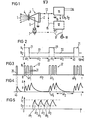
- Fig.1 eine Prinzipanordnung eines Flüssigkeitszerstäubers mit elektronischer Anregungsschaltung.
- Fig.2 Ein Diagramm des zeitlichen Taktverlaufs eingesgeister elektrischer Leistung.
- Fig.3 Ein Diagramm eines zeitlichen Taktverlaufs eingespeister elektrischer Leistung, wobei Gruppen von Speisetakten periodisch aufeinanderfolgen.
- Fig.4 Ein Diagramm des zeitlichen Verlaufs der Schwingungsamplitude des Ultraschall-Schwingers.
- Fig.5 ein Diagramm des zeitlichen Verlaufs der Amplitude des Ultraschall-Schwingers, wobei die Taktfolge nach den jeweils erreichten Schwingungsamplituden gesteuert wird.
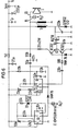
- Fig.6 Ein Schaltungsbeispiel zur Durchführung des erfindungsgemäßen Verfahrens.
- Fig.7 Ein Schaltbild für eine gemäß der Weiterbildung der Erfindung vorgesehene Überwachung des Betriebsverhaltens des Ultraschall-Schwingers.
- 1 shows a basic arrangement of a liquid atomizer with an electronic excitation circuit.
- Fig. 2 shows a diagram of the electrical energy's clock cycle.
- 3 shows a diagram of a time cycle of electrical power fed in, with groups of feed cycles periodically following one another.
- Fig.4 A diagram of the time course of the vibration amplitude of the ultrasonic vibrator.
- 5 shows a diagram of the time course of the amplitude of the ultrasonic vibrator, the clock sequence is controlled according to the vibration amplitudes achieved in each case.
- Fig.6 A circuit example for performing the method according to the invention.
- 7 shows a circuit diagram for a monitoring of the operating behavior of the ultrasonic vibrator provided in accordance with the development of the invention.
In Fig.1 ist mit 1 der gesamte Ultraschall-Schwinger bezeichnet. Es ist dies z.B. ein Ultraschall-Schwinger nach der deutschen Patentschrift 20 32 433. Dieser Schwinger umfaßt eine piezokeramische Scheibe 2 als piezoelektrischer Wandler, an die die elektrische Anregungsspannung anzulegen ist. Mit 3 ist die Arbeitsplatte bezeichnet, auf deren Oberfläche 4 die Flüssigkeitszerstäubung 5 erfolgt. Mit 6 ist eine Zuführungsleitung und mit 7 eine in dieser Zuführungsleitung installierte Pumpe für die der Oberfläche 4 zuzuführende, zu zerstäubende Flüs- sigkeit bezeichnet.In Figure 1, 1 denotes the entire ultrasonic vibrator. This is, for example, an ultrasonic vibrator according to
Mit 11 ist die eigentliche Anregungselektrpnik bezeichnet und mit 12 ist auf eine gemäß einer Weiterbildung vorgesehene zusätzliche Elektronikschaltung hingewiesen, die der Überwachung des betriebsmäßigen Schwingverhaltens des Ultraschall-Schwingers 1 dient.The actual excitation electronics are designated by 11 and reference is made to an additional electronic circuit provided according to a further development, which is used to monitor the operational vibration behavior of the ultrasonic vibrator 1.
Über die Leitung 13 wird die von der Schaltung 11 abgegebene elektrische Leistung dem Wandler 2 zugeführt. Die Schaltung 11 wird an den Anschlüssen 14 z.B. mit 220 Volt Wechselspannung oder auch mit 12 Volt Gleichspannung gespeist. Mit 15 ist eine Verbindungsleitung zur Schaltung 12 bezeichnet, nämlich über die während der Speisepause im Zeitintervall △t2 ein vom Wandler 2 zurückgeliefertes elektrisches Signal dieser Schaltung 12 zugeführt werden kann. Alternativ kann auch vorgesehen sein, daß der Wandler 2 eine zusätzliche (Rückkopplungs-)Elektrode hat, die über die Leitung 15 mit der Schaltung 12 verbunden ist. Die Leitung 16 zwischen den Schaltungen 11 und 12 dient dazu, von der Schaltung 12 Auswertesignale an die Schaltung 11 zu liefern, um diese zu steuern. Diese Steuerung kann sich insbesondere auf die Frequenz f der Anregungs-Wechselspannung (z.B. im Bereich von 100 kHz), auf die obere Schwelle S1 der Schwingungsamplitude des Schwingers 1 und/oder auf die untere Schwingungsamplitude S2 desselben beziehen.The electrical power output by the
Mit den Leitungen 17 ist auf Steuersignalausgänge der Schaltung 12 hingewiesen, z.B. zu einer Leuchtdiode 18, die als Betriebssignallampe dienen kann, und zur Pumpe 7, deren Steuerung aus der Schaltung 12 stets angepaßte Menge der Flüssigkeitszufuhr zur Oberfläche 4 des Schwingers 1 gewährleisten kann.
Das Diagramm der Fig.2 zeigt die über die Leitung 13 dem Wandler 2 und damit dem Schwinger 1 zugeführte elektrische Leistung N, aufgetragen über der Zeit. Die Takte 21 mit den ersten Zeitintervallen △t1 sind die eigentlichen Speiseintervalle. In.diesen Intervallen erhält der Schwinger 1 eine so große elektrische Leistung zugeführt, daß er selbst und damit auch die Arbeitsplatte 3 zuverlässig in die geforderte Ultraschall-Schwingung versetzt wird, und zwar unabhängig davon, ob auf der Oberfläche 4 der Platte 3 eine mehr oder weniger große Flüssigkeitsbelegung oder ein daran anhaftender Tropfen vorliegt. In den Zeitintervallen △t2 wird elektrische Leistung entsprechend den Takten 22 zugeführt. Die Leistung der Takte 22 kann so hoch bemessen sein, daß kontinuierliches Weiterschwingen kontinuierlich weitere Zerstäubung 5 bewirkt. Die elektrische Leistung der Takte 22 kann aber den Wert Null haben, d.h. man läßt in den zweiten Zeitintervallen △t2 den Schwinger 1 ausschwingen. Das Taktverhältnis △t1 : (△t1+△t2) beträgt z.B. 4 ms :20 ms, wobei letzterer Wert vorteilhafterweise aus der Netzfrequenz abgeleitet ist. Wichtig für das Taktverhältnis ist, daß zusammen mit dem Leistungsverhältnis N1 zu N2 die zulässigerweise zuzuführende mittlere elektrische Leistung nicht überschritten wird, aber dennoch mit der Höhe der Leistung N1 stets sicheres Anschwingen gewährleistet ist.The diagram in FIG. 2 shows the electrical power N supplied to the
Fig.3 zeigt das Diagramm der elektrischen Leistung N,wiederum aufgetragen über der Zeit t, jedoch mit Gruppen von - bei diesem Beispiel jeweils drei - Takten 31. Ein jeder dieser Takte 31 hat die Länge eines Zeitintervalls △t1' von z.B. 1 ms Dauer. Die Repetition dieser Takte 31 innerhalb einer Gruppe ist vorzugsweise periodisch mit. der Frequenz F1. Die Gruppen 32 bestehen aus der jeweiligen Anzahl der Einzeltakte 31, haben vorzugsweise ebenfalls periodische Repetition mit der Frequenz F2. Insbesondere wird diese Frequenz F2 zwischen 10 und 100 Hz, vorzugsweise 50 Hz (60 Hz), groß gemacht. Für das Maß der bereits obenerwähnten zugeführten mittleren elektrischen Leistung kommt es auf die Summe der Zeitintervalle △t1' einer einzelnen Gruppe 32 im Verhältnis zur Periodendauer der Repetitionsfrequenz F2 an.3 shows the diagram of the electrical power N, again plotted against the time t, but with groups of — in this example three
Das Diagramm der Fig.4 zeigt ein sich bei Speisung mit Anregungsleistung nach Fig.3 ergebender Amplitudenverlauf der Schwingung des Schwingers 1 bzw. der Arbeitsplatte 3. Da zwischen dem letzten Zeitintervall △t1' der einen Gruppe 32 und dem ersten Zeitintervall 4t1' der folgenden Gruppe 32 nach Fig.3 keine elektrische Leistungszufuhr vorgesehen ist, erfolgt in diesem Zeitintervall At2 ein asymptotisches Abklingen bis zum erneuten Wiederanschwingen.The diagram in FIG. 4 shows an amplitude profile of the oscillation of the vibrator 1 or the worktop 3 when the excitation power is supplied according to FIG. 3. Since between the last time interval △ t 1 'of one
Es ist bereits oben darauf hingewiesen worden, daß es von Vorteil sein kann, die Schwingungsamplitude A zwischen einer oberen Schwelle S1 und einer unteren Schwelle s2 zu halten, wie dies Fig.5 zeigt. Die Zeitintervalle des △t1 bzw. das Zeitintervall, in dem Zeitintervalle △t1' (Fig.3) vorliegen, und das Zeitintervall △t2 ergeben sich dann aus dem jeweiligen Betriebsschwingungsverhalten des Schwingers 1 und sind hier in ihrer zeitlichen Länge über die Dauer betrachtet variabel. Wie ebenfalls bereits oben erwähnt, erfolgt die Steuerung der Zeitintervalle △t1 und △t2 mit Hilfe der Schaltung 12, in der ein über die Leitung 15 geliefertes Rücksignal des Schwingers 1 ausgewertet wird.It has already been pointed out above that it can be advantageous to keep the oscillation amplitude A between an upper threshold S 1 and a lower threshold s 2 , as shown in FIG. The time intervals of △ t 1 or the time interval in which time intervals △ t 1 '(FIG. 3) are present, and the time interval △ t 2 then result from the respective operating vibration behavior of the vibrator 1 and are here in their temporal length over the Duration considered variable. As also mentioned above, the control of the time intervals und t 1 and △ t 2 takes place with the aid of the
Fig.6 zeigt ein vollständiges Schaltbild für eine Schaltung 11 zur Erzeugung der den Schwinger 1 speisenden elektrischen Leistung. Die Repetitionsfrequenz wird in dieser Schaltung von dem Generator 61 geliefert. Mit dem Generator 62 wird die Frequenz f der über die Leitung 13 zuzuführenden Wechselspannung, z.B. 100 kHz, gesteuert. Der Schaltungsteil 63 ist eine Treiberstufe und der Transistor 64 ist die Endstufe. Das Schaltungsteil 65 mit der Zenerdiode dient der Korrektur einer Schwankung der Versorgungsspannung 66. Die weiteren Einzelheiten der Schaltung gehen für den Fachmann ohne weiteres erkennbar aus dem Schaltbild hervor.FIG. 6 shows a complete circuit diagram for a
Fig.7 zeigt ein Schaltungsbeispiel für eine Schaltung 12. Es sind mit 71 das für eine Signalverzögerung vorgesehene Schaltungsteil und mit 72 der Signalkomparator bezeichnet. Auch dieses Schaltbild bedarf für den Fachmann keiner weiteren Erläuterung.FIG. 7 shows a circuit example for a
In Fig.3 ist mit 35 ein Vorimpuls gezeigt, der zeitlich vor Ingangsetzen des eigentlichen Zerstäuberbetriebs dem Schwinger 1 zugeführt wird. Es ist dies vorzugsweise ein Burstimpuls (Schwingungspaket) mit vorteilhafterweise eins bis zwanzig Schwingungen mit einer Frequenz, die wenigstens angenähert gleich der Resonanzfrequenz des Schwingers 1 ist.In FIG. 3, a pre-pulse is shown at 35, which is supplied to the oscillator 1 before the actual atomizing operation is started. This is preferably a burst pulse (oscillation packet) with advantageously one to twenty oscillations with a frequency that is at least approximately equal to the resonance frequency of the oscillator 1.
Der Vorimpuls stößt eine Schwingung des Schwingers 1 an und dessen Abklingschwingung 45 (in Fig.4) wird, wie oben schon beschrieben, zur Anfangssteuerung der Fre- . quenz f der über die Leitung 13 zuzuführenden Anregungswechselspannung genutzt.The pre-pulse triggers an oscillation of the oscillator 1 and its decay oscillation 45 (in FIG. 4) is, as already described above, for the initial control of the fre-. frequency f of the excitation AC voltage to be supplied via
Claims (19)
wobei der Wechsel vom jeweils ersten Zeitintervall (△t1, △t1') zum nachfolgenden zweiten Zeitintervall (△t2) bei Erreichen der oberen Schwelle (S1) erfolgt und wobei der Wechsel vom zweiten Zeitintervall (△t2) zum nachfolgenden ersten Zeitintervall (△t1, △t1') bei Erreichen der unteren Schwelle (S2) erfolgt.9. The method according to any one of claims 1 to 8, characterized in that an upper threshold (S 1 ) and a lower threshold (S 2 ) for the vibration amplitudes (A) of the vibrator (1) are predetermined, the upper threshold (S 1 ) is larger than the minimum amplitude (E) of the vibrator (1) necessary for atomization and
the change from the first time interval (△ t 1 , △ t 1 ') to the subsequent second time interval (△ t 2 ) when the upper threshold (S 1 ) is reached and the change from the second time interval (△ t 2 ) to the next first time interval (△ t 1 , △ t 1 ') when the lower threshold (S 2 ) is reached.
wobei ein vom Schwinger geliefertes,' diesem Abklingen entsprechendes elektrisches Signal (15) aufgenommen wird.10. The method according to any one of claims 2 to 9, characterized in that an evaluation of the time decay of the oscillation amplitude (A) of the oscillator (1) taking place in the second time interval (△ t 2 ) is carried out,
wherein a signal supplied by the transducer, 'this decay corresponding electrical signal (15) is received.
Priority Applications (1)
| Application Number | Priority Date | Filing Date | Title |
|---|---|---|---|
| AT84104426T ATE41887T1 (en) | 1983-04-22 | 1984-04-18 | PROCEDURE FOR OPERATING AN ULTRASONIC VIBRATOR FOR LIQUID ATOOMIZATION. |
Applications Claiming Priority (2)
| Application Number | Priority Date | Filing Date | Title |
|---|---|---|---|
| DE19833314609 DE3314609A1 (en) | 1983-04-22 | 1983-04-22 | METHOD FOR OPERATING AN ULTRASONIC VIBRATOR FOR LIQUID SPRAYING |
| DE3314609 | 1983-04-22 |
Publications (3)
| Publication Number | Publication Date |
|---|---|
| EP0123277A2 true EP0123277A2 (en) | 1984-10-31 |
| EP0123277A3 EP0123277A3 (en) | 1986-07-02 |
| EP0123277B1 EP0123277B1 (en) | 1989-04-05 |
Family
ID=6197071
Family Applications (1)
| Application Number | Title | Priority Date | Filing Date |
|---|---|---|---|
| EP84104426A Expired EP0123277B1 (en) | 1983-04-22 | 1984-04-18 | Method of driving an ultrasonic oscillator for an atomizing fluid |
Country Status (3)
| Country | Link |
|---|---|
| EP (1) | EP0123277B1 (en) |
| AT (1) | ATE41887T1 (en) |
| DE (2) | DE3314609A1 (en) |
Cited By (14)
| Publication number | Priority date | Publication date | Assignee | Title |
|---|---|---|---|---|
| EP0219693A1 (en) * | 1985-09-30 | 1987-04-29 | Siemens Aktiengesellschaft | Method for operating a fluid-atomising ultrasonic atomiser |
| EP0274136A2 (en) * | 1987-01-09 | 1988-07-13 | William L. Puskas | Multiparameter generator for ultrasonic transducers |
| GB2265845B (en) * | 1991-11-12 | 1996-05-01 | Medix Ltd | A nebuliser and nebuliser control system |
| US5834871A (en) * | 1996-08-05 | 1998-11-10 | Puskas; William L. | Apparatus and methods for cleaning and/or processing delicate parts |
| US6016821A (en) * | 1996-09-24 | 2000-01-25 | Puskas; William L. | Systems and methods for ultrasonically processing delicate parts |
| WO2000051747A1 (en) * | 1999-03-05 | 2000-09-08 | S. C. Johnson & Son, Inc. | Control system for atomizing liquids with a piezoelectric vibrator |
| US6313565B1 (en) | 2000-02-15 | 2001-11-06 | William L. Puskas | Multiple frequency cleaning system |
| US7211927B2 (en) | 1996-09-24 | 2007-05-01 | William Puskas | Multi-generator system for an ultrasonic processing tank |
| US7211928B2 (en) | 1996-08-05 | 2007-05-01 | Puskas William L | Apparatus, circuitry, signals and methods for cleaning and/or processing with sound |
| EP1875969A1 (en) * | 2006-07-07 | 2008-01-09 | L'oreal | Generator for exciting a piezoelectric transducer |
| US7336019B1 (en) | 2005-07-01 | 2008-02-26 | Puskas William L | Apparatus, circuitry, signals, probes and methods for cleaning and/or processing with sound |
| EP2244314A1 (en) | 2009-04-20 | 2010-10-27 | Zobele Holding SpA | Liquid atomiser with piezoelectric vibration device having an improved electronic control circuit, and activation method thereof |
| US9333523B2 (en) | 2013-09-09 | 2016-05-10 | Omnimist, Ltd. | Atomizing spray apparatus |
| CN114130547A (en) * | 2021-11-18 | 2022-03-04 | 安徽理工大学 | Medicament vaporization assembly and jet flow flotation column type device using same |
Families Citing this family (1)
| Publication number | Priority date | Publication date | Assignee | Title |
|---|---|---|---|---|
| US6822372B2 (en) | 1999-08-09 | 2004-11-23 | William L. Puskas | Apparatus, circuitry and methods for cleaning and/or processing with sound waves |
Citations (4)
| Publication number | Priority date | Publication date | Assignee | Title |
|---|---|---|---|---|
| FR2195172A5 (en) * | 1972-07-31 | 1974-03-01 | Matsushita Electric Ind Co Ltd | |
| FR2311595A1 (en) * | 1975-05-20 | 1976-12-17 | Matsushita Electric Ind Co Ltd | ULTRA-SOUND GENERATOR AND LIQUID ATOMIZING DEVICE WITH APPLICATION |
| EP0036186A2 (en) * | 1980-03-14 | 1981-09-23 | Siemens Aktiengesellschaft | Method for pulse activation of a piezo-electric sound transmitter-transducer |
| DE3013964A1 (en) * | 1980-04-11 | 1981-10-22 | Jürgen F. 8011 Poing Strutz | Circuits for stabilising ultrasonic generator and preventing drying - in prodn. of aerosols for breathing machines |
Family Cites Families (4)
| Publication number | Priority date | Publication date | Assignee | Title |
|---|---|---|---|---|
| DE2129665C3 (en) * | 1970-06-30 | 1981-02-12 | Siemens Ag, 1000 Berlin Und 8000 Muenchen | Device for atomizing liquids with a piezoelectrically excited vibration system |
| DE2312442A1 (en) * | 1973-03-13 | 1974-10-03 | Siemens Ag | ATOMIZER FOR LIQUIDS WITH PIEZOELECTRIC ULTRASONIC VIBRATOR |
| FR2421513A1 (en) * | 1978-03-31 | 1979-10-26 | Gaboriaud Paul | ULTRA-SONIC ATOMIZER WITH AUTOMATIC CONTROL |
| JPS5848225B2 (en) * | 1979-01-09 | 1983-10-27 | オムロン株式会社 | Atomization amount control method of ultrasonic liquid atomization device |
-
1983
- 1983-04-22 DE DE19833314609 patent/DE3314609A1/en not_active Withdrawn
-
1984
- 1984-04-18 DE DE8484104426T patent/DE3477550D1/en not_active Expired
- 1984-04-18 EP EP84104426A patent/EP0123277B1/en not_active Expired
- 1984-04-18 AT AT84104426T patent/ATE41887T1/en active
Patent Citations (4)
| Publication number | Priority date | Publication date | Assignee | Title |
|---|---|---|---|---|
| FR2195172A5 (en) * | 1972-07-31 | 1974-03-01 | Matsushita Electric Ind Co Ltd | |
| FR2311595A1 (en) * | 1975-05-20 | 1976-12-17 | Matsushita Electric Ind Co Ltd | ULTRA-SOUND GENERATOR AND LIQUID ATOMIZING DEVICE WITH APPLICATION |
| EP0036186A2 (en) * | 1980-03-14 | 1981-09-23 | Siemens Aktiengesellschaft | Method for pulse activation of a piezo-electric sound transmitter-transducer |
| DE3013964A1 (en) * | 1980-04-11 | 1981-10-22 | Jürgen F. 8011 Poing Strutz | Circuits for stabilising ultrasonic generator and preventing drying - in prodn. of aerosols for breathing machines |
Cited By (34)
| Publication number | Priority date | Publication date | Assignee | Title |
|---|---|---|---|---|
| US6288476B1 (en) | 1981-02-10 | 2001-09-11 | William L. Puskas | Ultrasonic transducer with bias bolt compression bolt |
| EP0219693A1 (en) * | 1985-09-30 | 1987-04-29 | Siemens Aktiengesellschaft | Method for operating a fluid-atomising ultrasonic atomiser |
| US4689515A (en) * | 1985-09-30 | 1987-08-25 | Siemens Aktiengesellschaft | Method for operating an ultrasonic frequency generator |
| EP0274136A2 (en) * | 1987-01-09 | 1988-07-13 | William L. Puskas | Multiparameter generator for ultrasonic transducers |
| EP0274136A3 (en) * | 1987-01-09 | 1989-08-02 | William L. Puskas | Multiparameter generator for ultrasonic transducers |
| GB2265845B (en) * | 1991-11-12 | 1996-05-01 | Medix Ltd | A nebuliser and nebuliser control system |
| US5551416A (en) * | 1991-11-12 | 1996-09-03 | Medix Limited | Nebuliser and nebuliser control system |
| US5834871A (en) * | 1996-08-05 | 1998-11-10 | Puskas; William L. | Apparatus and methods for cleaning and/or processing delicate parts |
| US6002195A (en) * | 1996-08-05 | 1999-12-14 | Puskas; William L. | Apparatus and methods for cleaning and/or processing delicate parts |
| US7211928B2 (en) | 1996-08-05 | 2007-05-01 | Puskas William L | Apparatus, circuitry, signals and methods for cleaning and/or processing with sound |
| US6946773B2 (en) | 1996-08-05 | 2005-09-20 | Puskas William L | Apparatus and methods for cleaning and/or processing delicate parts |
| US6181051B1 (en) | 1996-08-05 | 2001-01-30 | William L. Puskas | Apparatus and methods for cleaning and/or processing delicate parts |
| US6914364B2 (en) | 1996-08-05 | 2005-07-05 | William L. Puskas | Apparatus and methods for cleaning and/or processing delicate parts |
| US6433460B1 (en) | 1996-08-05 | 2002-08-13 | William L. Puskas | Apparatus and methods for cleaning and/or processing delicate parts |
| US6538360B2 (en) | 1996-08-05 | 2003-03-25 | William L. Puskas | Multiple frequency cleaning system |
| US6016821A (en) * | 1996-09-24 | 2000-01-25 | Puskas; William L. | Systems and methods for ultrasonically processing delicate parts |
| US6242847B1 (en) | 1996-09-24 | 2001-06-05 | William L. Puskas | Ultrasonic transducer with epoxy compression elements |
| US7211927B2 (en) | 1996-09-24 | 2007-05-01 | William Puskas | Multi-generator system for an ultrasonic processing tank |
| US7004016B1 (en) | 1996-09-24 | 2006-02-28 | Puskas William L | Probe system for ultrasonic processing tank |
| US6172444B1 (en) | 1996-09-24 | 2001-01-09 | William L. Puskas | Power system for impressing AC voltage across a capacitive element |
| AU767322B2 (en) * | 1999-03-05 | 2003-11-06 | S.C. Johnson & Son, Inc. | Control system for atomizing liquids with a piezoelectric vibrator |
| US6296196B1 (en) | 1999-03-05 | 2001-10-02 | S. C. Johnson & Son, Inc. | Control system for atomizing liquids with a piezoelectric vibrator |
| JP2002537985A (en) * | 1999-03-05 | 2002-11-12 | エス.シー. ジョンソン アンド サン、インコーポレイテッド | Control system for atomizing liquid using piezoelectric vibrator |
| US6439474B2 (en) | 1999-03-05 | 2002-08-27 | S. C. Johnson & Son, Inc. | Control system for atomizing liquids with a piezoelectric vibrator |
| WO2000051747A1 (en) * | 1999-03-05 | 2000-09-08 | S. C. Johnson & Son, Inc. | Control system for atomizing liquids with a piezoelectric vibrator |
| US6313565B1 (en) | 2000-02-15 | 2001-11-06 | William L. Puskas | Multiple frequency cleaning system |
| US7336019B1 (en) | 2005-07-01 | 2008-02-26 | Puskas William L | Apparatus, circuitry, signals, probes and methods for cleaning and/or processing with sound |
| FR2903331A1 (en) * | 2006-07-07 | 2008-01-11 | Oreal | GENERATOR FOR EXCITING A PIEZOELECTRIC TRANSDUCER |
| EP1875969A1 (en) * | 2006-07-07 | 2008-01-09 | L'oreal | Generator for exciting a piezoelectric transducer |
| US7960894B2 (en) | 2006-07-07 | 2011-06-14 | L'oreal S.A. | Generator for exciting piezoelectric transducer |
| EP2244314A1 (en) | 2009-04-20 | 2010-10-27 | Zobele Holding SpA | Liquid atomiser with piezoelectric vibration device having an improved electronic control circuit, and activation method thereof |
| US9333523B2 (en) | 2013-09-09 | 2016-05-10 | Omnimist, Ltd. | Atomizing spray apparatus |
| CN114130547A (en) * | 2021-11-18 | 2022-03-04 | 安徽理工大学 | Medicament vaporization assembly and jet flow flotation column type device using same |
| CN114130547B (en) * | 2021-11-18 | 2023-06-16 | 安徽理工大学 | Medicament vaporization assembly and jet flow flotation column type device using same |
Also Published As
| Publication number | Publication date |
|---|---|
| EP0123277B1 (en) | 1989-04-05 |
| DE3477550D1 (en) | 1989-05-11 |
| DE3314609A1 (en) | 1984-10-25 |
| ATE41887T1 (en) | 1989-04-15 |
| EP0123277A3 (en) | 1986-07-02 |
Similar Documents
| Publication | Publication Date | Title |
|---|---|---|
| EP0123277B1 (en) | Method of driving an ultrasonic oscillator for an atomizing fluid | |
| DE60012566T2 (en) | SWITCHING TOOL CONVERTER WITH A PIEZOELECTRIC CONVERTER | |
| DE602005003340T2 (en) | ELECTRONIC DRIVE SYSTEM FOR A DROP SPRAY GENERATING DEVICE | |
| DE4122945A1 (en) | MICROPROCESSOR CONTROLLED DC CONVERTER | |
| DE10122065B4 (en) | Apparatus for generating liquid droplets with a vibrated membrane | |
| DE2721225A1 (en) | CIRCUIT ARRANGEMENT FOR AUTOMATIC FREQUENCY CONTROL OF AN ULTRASONIC TRANSMITTER | |
| DE3431481A1 (en) | Method for operating ultrasound power oscillators, especially in apparatuses for tartar removal | |
| EP0036186A2 (en) | Method for pulse activation of a piezo-electric sound transmitter-transducer | |
| DE2201156A1 (en) | Electrical signal generator, in particular measuring transmitter | |
| DE2823155A1 (en) | ELECTRIC CONTROL CIRCUIT FOR A PIEZOELECTRIC TRANSDUCER | |
| DE4036618C3 (en) | Device for driving a piezoelectric vibrator | |
| WO1998048597A1 (en) | Circuitry for dimming a fluorescent lamp | |
| DE3440538C1 (en) | Proximity switch | |
| DE2803847C2 (en) | Device for wireless remote switching on and off of electrical devices | |
| DE3417102A1 (en) | METHOD FOR CONTROLLING A MONOSTABLE RELAY AND ARRANGEMENT FOR IMPLEMENTING THE METHOD | |
| DE1927673A1 (en) | Method and circuit arrangement for oscillator vibration generator | |
| EP0736639B1 (en) | Dewatering device for masonry | |
| WO1988000408A1 (en) | Process for operating a switching controller and switching controler operating according to this process | |
| DE3740334A1 (en) | Multi-frequency signal drive circuit for a cathode ray tube device | |
| DE2228008C3 (en) | Method and device for generating a transmission signal with a transmission frequency in a rigid relationship to the network frequency of the power supply network and application of this method | |
| DE1205319B (en) | Oscillating circuit for a generator for ultrasound | |
| DE2427042C3 (en) | Circuit arrangement for converting an electrical alternating current signal of a relatively low frequency into an acoustic signal of a frequency deviating therefrom in telecommunications systems | |
| DE4200194C2 (en) | Vibratory conveyor arrangement | |
| DE1964287C3 (en) | Start-stop oscillator, especially for generating short-term color carrier oscillations | |
| DE2400192A1 (en) | LF SIGNAL GENERATOR |
Legal Events
| Date | Code | Title | Description |
|---|---|---|---|
| PUAI | Public reference made under article 153(3) epc to a published international application that has entered the european phase |
Free format text: ORIGINAL CODE: 0009012 |
|
| AK | Designated contracting states |
Designated state(s): AT BE CH DE FR GB IT LI NL SE |
|
| 17P | Request for examination filed |
Effective date: 19841221 |
|
| PUAL | Search report despatched |
Free format text: ORIGINAL CODE: 0009013 |
|
| AK | Designated contracting states |
Kind code of ref document: A3 Designated state(s): AT BE CH DE FR GB IT LI NL SE |
|
| 17Q | First examination report despatched |
Effective date: 19880531 |
|
| GRAA | (expected) grant |
Free format text: ORIGINAL CODE: 0009210 |
|
| AK | Designated contracting states |
Kind code of ref document: B1 Designated state(s): AT BE CH DE FR GB IT LI NL SE |
|
| REF | Corresponds to: |
Ref document number: 41887 Country of ref document: AT Date of ref document: 19890415 Kind code of ref document: T |
|
| REF | Corresponds to: |
Ref document number: 3477550 Country of ref document: DE Date of ref document: 19890511 |
|
| ET | Fr: translation filed | ||
| ITF | It: translation for a ep patent filed |
Owner name: STUDIO JAUMANN |
|
| GBT | Gb: translation of ep patent filed (gb section 77(6)(a)/1977) | ||
| PLBE | No opposition filed within time limit |
Free format text: ORIGINAL CODE: 0009261 |
|
| STAA | Information on the status of an ep patent application or granted ep patent |
Free format text: STATUS: NO OPPOSITION FILED WITHIN TIME LIMIT |
|
| 26N | No opposition filed | ||
| ITTA | It: last paid annual fee | ||
| PGFP | Annual fee paid to national office [announced via postgrant information from national office to epo] |
Ref country code: AT Payment date: 19930319 Year of fee payment: 10 |
|
| PGFP | Annual fee paid to national office [announced via postgrant information from national office to epo] |
Ref country code: BE Payment date: 19930420 Year of fee payment: 10 |
|
| PGFP | Annual fee paid to national office [announced via postgrant information from national office to epo] |
Ref country code: NL Payment date: 19930430 Year of fee payment: 10 |
|
| PGFP | Annual fee paid to national office [announced via postgrant information from national office to epo] |
Ref country code: CH Payment date: 19930712 Year of fee payment: 10 |
|
| PG25 | Lapsed in a contracting state [announced via postgrant information from national office to epo] |
Ref country code: AT Effective date: 19940418 |
|
| PG25 | Lapsed in a contracting state [announced via postgrant information from national office to epo] |
Ref country code: LI Effective date: 19940430 Ref country code: CH Effective date: 19940430 Ref country code: BE Effective date: 19940430 |
|
| BERE | Be: lapsed |
Owner name: SIEMENS A.G. BERLIN UND MUNCHEN Effective date: 19940430 |
|
| PG25 | Lapsed in a contracting state [announced via postgrant information from national office to epo] |
Ref country code: NL Effective date: 19941101 |
|
| NLV4 | Nl: lapsed or anulled due to non-payment of the annual fee | ||
| REG | Reference to a national code |
Ref country code: CH Ref legal event code: PL |
|
| EAL | Se: european patent in force in sweden |
Ref document number: 84104426.6 |
|
| PGFP | Annual fee paid to national office [announced via postgrant information from national office to epo] |
Ref country code: DE Payment date: 19980618 Year of fee payment: 15 |
|
| PGFP | Annual fee paid to national office [announced via postgrant information from national office to epo] |
Ref country code: GB Payment date: 19990413 Year of fee payment: 16 |
|
| PGFP | Annual fee paid to national office [announced via postgrant information from national office to epo] |
Ref country code: SE Payment date: 19990414 Year of fee payment: 16 |
|
| PGFP | Annual fee paid to national office [announced via postgrant information from national office to epo] |
Ref country code: FR Payment date: 19990422 Year of fee payment: 16 |
|
| PG25 | Lapsed in a contracting state [announced via postgrant information from national office to epo] |
Ref country code: DE Free format text: LAPSE BECAUSE OF NON-PAYMENT OF DUE FEES Effective date: 20000201 |
|
| PG25 | Lapsed in a contracting state [announced via postgrant information from national office to epo] |
Ref country code: GB Free format text: LAPSE BECAUSE OF NON-PAYMENT OF DUE FEES Effective date: 20000418 |
|
| PG25 | Lapsed in a contracting state [announced via postgrant information from national office to epo] |
Ref country code: SE Free format text: LAPSE BECAUSE OF NON-PAYMENT OF DUE FEES Effective date: 20000419 |
|
| GBPC | Gb: european patent ceased through non-payment of renewal fee |
Effective date: 20000418 |
|
| EUG | Se: european patent has lapsed |
Ref document number: 84104426.6 |
|
| PG25 | Lapsed in a contracting state [announced via postgrant information from national office to epo] |
Ref country code: FR Free format text: LAPSE BECAUSE OF NON-PAYMENT OF DUE FEES Effective date: 20001229 |
|
| REG | Reference to a national code |
Ref country code: FR Ref legal event code: ST |