EP0127752A1 - Liquefied gas pump - Google Patents
Liquefied gas pump Download PDFInfo
- Publication number
- EP0127752A1 EP0127752A1 EP84104076A EP84104076A EP0127752A1 EP 0127752 A1 EP0127752 A1 EP 0127752A1 EP 84104076 A EP84104076 A EP 84104076A EP 84104076 A EP84104076 A EP 84104076A EP 0127752 A1 EP0127752 A1 EP 0127752A1
- Authority
- EP
- European Patent Office
- Prior art keywords
- liquefied gas
- insulated tank
- pump
- driving shaft
- bearings
- Prior art date
- Legal status (The legal status is an assumption and is not a legal conclusion. Google has not performed a legal analysis and makes no representation as to the accuracy of the status listed.)
- Granted
Links
- 239000007788 liquid Substances 0.000 claims description 21
- 238000005086 pumping Methods 0.000 claims description 7
- 230000001105 regulatory effect Effects 0.000 claims description 2
- 239000007789 gas Substances 0.000 description 35
- 239000001307 helium Substances 0.000 description 26
- 229910052734 helium Inorganic materials 0.000 description 26
- SWQJXJOGLNCZEY-UHFFFAOYSA-N helium atom Chemical compound [He] SWQJXJOGLNCZEY-UHFFFAOYSA-N 0.000 description 26
- 230000000694 effects Effects 0.000 description 6
- 238000001816 cooling Methods 0.000 description 4
- 239000011810 insulating material Substances 0.000 description 4
- 230000008016 vaporization Effects 0.000 description 4
- 238000009834 vaporization Methods 0.000 description 4
- 238000009434 installation Methods 0.000 description 3
- 239000000498 cooling water Substances 0.000 description 2
- 238000007599 discharging Methods 0.000 description 2
- 238000002309 gasification Methods 0.000 description 2
- 238000009413 insulation Methods 0.000 description 2
- 238000012423 maintenance Methods 0.000 description 2
- 230000000630 rising effect Effects 0.000 description 2
- 239000007787 solid Substances 0.000 description 2
- 239000004698 Polyethylene Substances 0.000 description 1
- 230000005540 biological transmission Effects 0.000 description 1
- 230000006866 deterioration Effects 0.000 description 1
- 230000002708 enhancing effect Effects 0.000 description 1
- 230000002349 favourable effect Effects 0.000 description 1
- 239000012530 fluid Substances 0.000 description 1
- 239000000314 lubricant Substances 0.000 description 1
- 238000003754 machining Methods 0.000 description 1
- 230000002093 peripheral effect Effects 0.000 description 1
- 239000004033 plastic Substances 0.000 description 1
- 229920003023 plastic Polymers 0.000 description 1
- -1 polyethylene Polymers 0.000 description 1
- 229920000573 polyethylene Polymers 0.000 description 1
- 230000005855 radiation Effects 0.000 description 1
- 125000006850 spacer group Chemical group 0.000 description 1
- 229910001220 stainless steel Inorganic materials 0.000 description 1
- 239000010935 stainless steel Substances 0.000 description 1
Images


Classifications
-
- F—MECHANICAL ENGINEERING; LIGHTING; HEATING; WEAPONS; BLASTING
- F04—POSITIVE - DISPLACEMENT MACHINES FOR LIQUIDS; PUMPS FOR LIQUIDS OR ELASTIC FLUIDS
- F04D—NON-POSITIVE-DISPLACEMENT PUMPS
- F04D7/00—Pumps adapted for handling specific fluids, e.g. by selection of specific materials for pumps or pump parts
- F04D7/02—Pumps adapted for handling specific fluids, e.g. by selection of specific materials for pumps or pump parts of centrifugal type
-
- F—MECHANICAL ENGINEERING; LIGHTING; HEATING; WEAPONS; BLASTING
- F04—POSITIVE - DISPLACEMENT MACHINES FOR LIQUIDS; PUMPS FOR LIQUIDS OR ELASTIC FLUIDS
- F04D—NON-POSITIVE-DISPLACEMENT PUMPS
- F04D29/00—Details, component parts, or accessories
- F04D29/58—Cooling; Heating; Diminishing heat transfer
- F04D29/586—Cooling; Heating; Diminishing heat transfer specially adapted for liquid pumps
- F04D29/5893—Cooling; Heating; Diminishing heat transfer specially adapted for liquid pumps heat insulation or conduction
Definitions
- the present invention relates to a pump for supplying cryogenic liquefied gases such as LHe, LN 2 , LH 2 and LNe, and more particularly to a pump well suited for supplying liquid helium.
- cryogenic liquefied gases such as LHe, LN 2 , LH 2 and LNe
- a motor is disposed in the upper part of a storage tank for a liquefied gas or a cryostat, and a driving shaft is extended therefrom into the tank and has an impeller connected to its lower end.
- Bearings used are ball bearings.
- the motor at the room temperature and the pump impeller at a very low temperature hold a temperature difference owing to the resistances of heat transmission by the driving shaft and a housing made of stainless steel.
- An object of the present invention is to eliminate the disadvantages of the prior-art cryogenic liquefied gas pumps and to provide a compact pump , of high reliability.
- the present invention is characterized in that a double insulated tank is formed inside a vessel for storing a liquefied gas so as to maintain the interior of the insulated tank at a room'temperature, that a motor and bearings are unitarily received in the interior, and that an impeller located in a very low temperature region is driven by the motor placed in the room temperature region.
- Another characterizing feature of the present invention is that the driving shaft, housing and insulated tank of a pump are cooled by the latent heat of vaporization during the gasification of a liquefied gas and the sensible heat of the gas at a low temperature, to reduce the heat leakage to a very low temperature region from a room temperature region, thereby enhancing the performance and preventing the thermal deformations of the driving shaft and the housing, whereby a stable operation is permitted, and the reliability is enhanced.
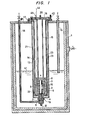
- Fig. 1 is a vertical sectional view of a whole liquefied gas vessel which is equipped with a liquefied gas pump embodying the present invention
- Fig. 2 is an enlarged sectional view of a pump driving portion in Fig. 1.
- Fig. 3 is a vertical sectional view of a liquefied gas pump according to another embodiment of the present invention, while Fig. 4 is an enlarged sectional view of a pump driving portion'in Fig. 3.
- numeral 1 designates a cryogenic vessel such as liquid helium storage tank or cryostat, which is furnished with a pipe lA for feeding liquid helium into the vessel 1 and a pipe 1B for discharging the liquid helium.
- Numeral 2 designates a pump proper, which consists of an impeller 3, a driving shaft 4, an electric motor 5 and bearings 6, 7, 8.
- Shown at numeral 13 is an outer insulated tank, inside which an inner insulated tank 14 is disposed.
- the temperature of the gas is in a room temperature region inside the inner insulated tank 14, and a pump housing 15 is received here.
- a pump housing 15 Arranged within the pump housing are the motor 5, driving shaft 4 and bearings 6, 7, 8 of the pump proper 2.
- the upper parts of the outer insulated tank 13 and inner insulated tank 14 are fixed to a flange 17, while the lower ends thereof are so fixed that positional deviations attributed to thermal shrinkage can be absorbed through bellows 19.
- a radiation shield 21 is disposed between both the insulated tanks, and its lower part is held by a spacer 22.
- a multilayer insulating material 23 is wound on the inner surface of the outer insulated tank 13 and the outer surface of the inner insulated tank 14.
- the flange 17 is provided with an evacuating pipe 40, and the interspace between both the insulated tanks is rendered vacuum for thermal insulation.
- the pump housing 15 is fixed to an upper flange 18 by a supporting pipe 16.
- the flange 18 is provided with a vent tube 20 for helium gas produced by vaporization and a conduit 45 for the leads 44 of the motor.
- the flange 17 for assembling the insulated tanks is mounted on the upper plate 25 of the low temperature vessel 1 such as liquid helium storage tank or cryostat, and the flange 18 for assembling the pump proper is further mounted on the insulated tank assembling flange 17.
- the mounting position of the pump proper 2 is set to be below the liquid level 41 of the liquid helium.
- the impeller 3 is attached to the lower end of the driving shaft 4, the rotor 30 of the motor 5 is mounted centrally on the upper part, and the upper end is formed into a disc 29 for a thrust bearing.
- the stator 31 of the motor is situated in a position confronting the rotor 30, and journal bearings 6 and 7 are disposed under and over them.
- the tilting pad type self acting gas bearings are used, and a tilting pad 26 is supported by a pivot 27.
- a self acting gas bearing is also employed for the thrust bearing 8.
- a shaft case 35B and an inner case 35A are disposed around the driving shaft 4, and a solid insulating material 36 is put in the interspace between both the cases.
- the liquid helium When the stator.31 of the motor 5 is energized to rotate the impeller 3 of the pump, the liquid helium is drawn by suction through a suction port 8' and is delivered from a discharge port 9 to the discharging pipe 1B. In this case, the liquid helium rises along an annular minute gap 37 which is formed between the driving shaft 4 and the shaft case 35B or between the former and the bearings 6, 7, 8 and along an annular minute gap 38 which is formed between the outer case 14A and the inner case 35A or between the inner insulated tank 14 and the housing 15, and it vaporizes midway.
- the helium gas having risen around the driving shaft 4 and the helium gas having risen along the annular minute gap 38 between the inner insulated tank 14 and the housing 15 are released through the supporting pipe 16 from a release aperture 32 provided in the upper part of the pump housing 15 and from a release aperture 33 provided in the lower part of the supporting pipe 16.
- the room temperature zone can be secured inside the liquid helium temperature region by the use of the double insulated tank consisting of the outer insulated tank 13 and the inner insulated tank 14. Therefore, the self acting gas bearings can be adopted as the bearings of the pump. This brings forth the effect that the helium gas is not . contaminated, so the reliability can be enhanced.
- the double insulated tank structure employed makes it possible to secure the room temperature zone inside the cryogenic region of the liquefied gas temperature and to adopt bearings which use a lubricant.
- the driving shaft can be shortened owing to the short distance between the motor and the impeller, there are the effects that the reliability is enhanced, that high-speed rotation is permitted and that the structure can be simplified.
- the double insulated tank structure can prevent heat leakage to the cryogenic liquefied gas region, the cryogenic'liquefied gas is difficult of vaporization, which attains the effects of the high efficiency and stable operation of the pump.
- the double insulated tank and the pump housing for receiving the pump proper are separately mounted, there is the effect that the maintenance is facilitated by the simple detachment of the pump.
- a flange 17 is provided with an evacuating pipe 40, and the interspace between both insulated tanks 13 and 14 is rendered vacuum for thermal insulation.
- a housing 15 is fixed to an upper flange 18 by a supporting pipe 16.
- the flange 18 is provided with vent tubes 20 and 47 for helium gas produced by vaporization and a conduit 45 for the leads 44 of a motor 5. Further, the helium vent tubes 20 and 47 are respectively provided with flow rate regulator valves 46 and 48.
- the flange 17 for assembling the insulated tanks is mounted on the upper plate 25 of a liquid helium storage tank, a cryostat or the like, while the flange 18 for assembling a pump proper 2 is further mounted on the insulated tank assembling flange 17.
- the pump proper is installed below the liquid level 41 of liquid helium.
- An impeller 3 is attached to the lower end of a driving shaft 4, the rotor 30 of the motor 5 is mounted centrally on the upper part, and the upper end is formed into a disc 29 for a thrust bearing.
- the stator 31 of the motor is situated in a position confronting the rotor 30, and journal bearings 6 and 7 are disposed under and over them.
- the tilting pad type self acting gas bearings are used, and a tilting pad 26 is supported by a pivot 27.
- a self acting gas bearing is also employed for the thrust bearing 8.
- An inner case 35A and a shaft case 35B are disposed between the impeller 3 and the lower journal bearing 6, and a solid insulating material 36 such as foamed polyethylene is put in the interspace between both the cases.
- the lower end of this portion is in contact with the liquid helium and becomes a very low temperature region, whereas the upper end becomes near the room temperature.
- the liquid helium enters from the lower part into an annular minute gap 37 around the driving shaft 4, it is gasified by the heat leakage from the upper part.
- the gas rises along the minute gap 37 between the driving shaft 4 and the bearing 6, stator 31 and bearings 7 and 8, and it is released out of the system via a release aperture 32, the supporting pipe 16, the vent tube 20 and the flow rate regulator valve 46.
- the liquid helium enters from the lower part into an annular minute gap 38 defined between the inner case 35A and the inner insulated tank 14, and it is gasified in the lower portion of the insulating material by the heat leakage. The gas is released out of the system via the interior of the inner insulated tank 14, the vent tube 47 and the flow rate regulator valve 48.
- the helium gas produced by the gasification in low temperature parts within the gaps 37 and 38 cools the pump proper and the housing in the course of rising along the respective gaps.
- the quantities of the helium gas to flow out from the vent tubes pipes 20 and 47 may be adjusted in " correspondence with the quantities of heat leakage due to the conductions through the driving shaft and the driving shaft side housing and the heat leakage due to the conductions through the outside housing and the inner insulated tank.
- the inventors have obtained favorable results by adjusting the flow rates in a range of 1 : 5 to 50.
- the stable operation of the pump has become possible by individually regulating the flow rate of the helium gas rising along the gaps 37 and 38, thereby to reduce the heat leakage and also to uniformly cool the driving shaft, housing and inner insulated tank.
- the gas flow rates can be separately adjusted. This brings forth the effect that the cooling is performed in conformity with • the heat leakage to the respective parts, to efficiently reduce the heat leakage.
- Another effect is that the driving shaft, the inner and outer sides of the housing and the inner insulated tank are uniformly cooled, so the positional deviation between the driving shaft and the housing or tfie inner insulated tank ascribable to thermal deformations does not arise, and a stable operation becomes possible.
- the heat leakage includes heat generated during the rotation of the motor, besides the attribution of the conductions from the room temperature parts.
- the heat of the motor can also be removed by providing the room temperature part of the housing 15 with a cooling coil or jacket through which cooling water is caused to flow.
- the unitary structure of the pump proper 2 necessitates a sealed structure which withstands the fluid pressure difference between the suction port 8' and the discharge port 9.
- a seal ring 51 made of plastics is detachably mounted on the tip end of the housing 15.
- the structure can compensate dimensional errors in machining as well as installation errors involved when the housing 15 with the pump proper 2 received . therein is inserted into the inner insulated tank 14 from above for installation, and adjustments at the installation are facilitated.
- the maintenance including the repair of the sealed portion due to deterioration is easy because the exchange of the seal ring is easy.
Abstract
Description
- The present invention relates to a pump for supplying cryogenic liquefied gases such as LHe, LN2, LH2 and LNe, and more particularly to a pump well suited for supplying liquid helium.
- In an example of a prior-art liquefied gas pump for very low temperatures, as described by L. B. Dinaburg et al. in CRYOGENICS, JULY 1977, pp. 439 - 440, a motor is disposed in the upper part of a storage tank for a liquefied gas or a cryostat, and a driving shaft is extended therefrom into the tank and has an impeller connected to its lower end. Bearings used are ball bearings.
- The motor at the room temperature and the pump impeller at a very low temperature hold a temperature difference owing to the resistances of heat transmission by the driving shaft and a housing made of stainless steel.
- Since the prior-art cryogenic liquefied gas pump has such structure, the driving shaft becomes long, high speed rotation is impossible and the structure is complicated. Another disadvantage is that, since the bearing of the impeller is used at very low temperature, it is lubricated with the liquefied gas and wears away heavily.
- On the other hand, P. R. Ludtke has published a liquefied gas pump which employs a submerged motor. That is, a pump indicated on
page 3 and Fig. 1 in NBSIR 75-816 JULY 1975 (U. S. Department of Commerce) has a short driving shaft. However, the whole structure is placed in a cryogenic region, and ball bearings are used and therefore wear away heavily. These lead to the disadvantages that the reliability is low and that heat generated by the motor becomes the loss of a liquefied gas. Similar pumping systems of the submerged type are also disclosed in U.S. Patents 3,369,715 and 3,876,120. - An object of the present invention is to eliminate the disadvantages of the prior-art cryogenic liquefied gas pumps and to provide a compact pump , of high reliability.
- The present invention is characterized in that a double insulated tank is formed inside a vessel for storing a liquefied gas so as to maintain the interior of the insulated tank at a room'temperature, that a motor and bearings are unitarily received in the interior, and that an impeller located in a very low temperature region is driven by the motor placed in the room temperature region.
- Another characterizing feature of the present invention is that the driving shaft, housing and insulated tank of a pump are cooled by the latent heat of vaporization during the gasification of a liquefied gas and the sensible heat of the gas at a low temperature, to reduce the heat leakage to a very low temperature region from a room temperature region, thereby enhancing the performance and preventing the thermal deformations of the driving shaft and the housing, whereby a stable operation is permitted, and the reliability is enhanced.
- Fig. 1 is a vertical sectional view of a whole liquefied gas vessel which is equipped with a liquefied gas pump embodying the present invention, while Fig. 2 is an enlarged sectional view of a pump driving portion in Fig. 1.
- Fig. 3 is a vertical sectional view of a liquefied gas pump according to another embodiment of the present invention, while Fig. 4 is an enlarged sectional view of a pump driving portion'in Fig. 3.
- An embodiment of the present invention will now be described with reference to Fig. 1. Referring to the figure, numeral 1 designates a cryogenic vessel such as liquid helium storage tank or cryostat, which is furnished with a pipe lA for feeding liquid helium into the vessel 1 and a
pipe 1B for discharging the liquid helium. Numeral 2 designates a pump proper, which consists of animpeller 3, adriving shaft 4, anelectric motor 5 andbearings - Shown at
numeral 13 is an outer insulated tank, inside which an inner insulatedtank 14 is disposed. The temperature of the gas is in a room temperature region inside the inner insulatedtank 14, and apump housing 15 is received here. Arranged within the pump housing are themotor 5, drivingshaft 4 andbearings - The upper parts of the outer insulated
tank 13 and inner insulatedtank 14 are fixed to aflange 17, while the lower ends thereof are so fixed that positional deviations attributed to thermal shrinkage can be absorbed throughbellows 19. Aradiation shield 21 is disposed between both the insulated tanks, and its lower part is held by aspacer 22. In addition, amultilayer insulating material 23 is wound on the inner surface of the outer insulatedtank 13 and the outer surface of the inner insulatedtank 14. Further, theflange 17 is provided with an evacuatingpipe 40, and the interspace between both the insulated tanks is rendered vacuum for thermal insulation. Thepump housing 15 is fixed to anupper flange 18 by a supportingpipe 16. Theflange 18 is provided with avent tube 20 for helium gas produced by vaporization and aconduit 45 for theleads 44 of the motor. Theflange 17 for assembling the insulated tanks is mounted on theupper plate 25 of the low temperature vessel 1 such as liquid helium storage tank or cryostat, and theflange 18 for assembling the pump proper is further mounted on the insulatedtank assembling flange 17. The mounting position of the pump proper 2 is set to be below theliquid level 41 of the liquid helium. - The details of the pump proper 2 will be described with reference to Fig. 2. The
impeller 3 is attached to the lower end of thedriving shaft 4, therotor 30 of themotor 5 is mounted centrally on the upper part, and the upper end is formed into adisc 29 for a thrust bearing. Thestator 31 of the motor is situated in a position confronting therotor 30, andjournal bearings pad 26 is supported by apivot 27. A self acting gas bearing is also employed for the thrust bearing 8. Ashaft case 35B and aninner case 35A are disposed around the drivingshaft 4, and a solid insulatingmaterial 36 is put in the interspace between both the cases. An abrupt temperature distribution is established in this portion because the lower end is in contact with the liquid helium and the upper end is at a temperature near room temperature. The parts of the pump proper 2 except theimpeller 3 are received in thepump housing 15 and theinner case 35A. In Fig. 2, the lead to thestator 31 of themotor 5 has been omitted: Anouter case 14A is disposed unitarily with the inner insulatedtank 14, and theinner case 35A is received inside it. - When the stator.31 of the
motor 5 is energized to rotate theimpeller 3 of the pump, the liquid helium is drawn by suction through a suction port 8' and is delivered from adischarge port 9 to thedischarging pipe 1B. In this case, the liquid helium rises along anannular minute gap 37 which is formed between thedriving shaft 4 and theshaft case 35B or between the former and thebearings annular minute gap 38 which is formed between theouter case 14A and theinner case 35A or between the inner insulatedtank 14 and thehousing 15, and it vaporizes midway. The helium gas having risen around thedriving shaft 4 and the helium gas having risen along theannular minute gap 38 between the inner insulatedtank 14 and thehousing 15 are released through the supportingpipe 16 from arelease aperture 32 provided in the upper part of thepump housing 15 and from a release aperture 33 provided in the lower part of the supportingpipe 16. - To the end of eliminating heat generated by the
motor 5, it is also possible to pass cooling water through a jacket disposed on or a cooling pipe wound round the peripheral wall portion of thehousing 15. - As described above, according to this embodiment, the room temperature zone can be secured inside the liquid helium temperature region by the use of the double insulated tank consisting of the outer insulated
tank 13 and the inner insulatedtank 14. Therefore, the self acting gas bearings can be adopted as the bearings of the pump. This brings forth the effect that the helium gas is not . contaminated, so the reliability can be enhanced. - In addition, according to the present invention, the double insulated tank structure employed makes it possible to secure the room temperature zone inside the cryogenic region of the liquefied gas temperature and to adopt bearings which use a lubricant. Moreover, since the driving shaft can be shortened owing to the short distance between the motor and the impeller, there are the effects that the reliability is enhanced, that high-speed rotation is permitted and that the structure can be simplified. Besides, since the double insulated tank structure can prevent heat leakage to the cryogenic liquefied gas region, the cryogenic'liquefied gas is difficult of vaporization, which attains the effects of the high efficiency and stable operation of the pump. Further, since the double insulated tank and the pump housing for receiving the pump proper are separately mounted, there is the effect that the maintenance is facilitated by the simple detachment of the pump.
- Another embodiment of the present invention will be described with reference to Fig. 3. In this embodiment, a
flange 17 is provided with an evacuatingpipe 40, and the interspace between both insulatedtanks housing 15 is fixed to anupper flange 18 by a supportingpipe 16. Theflange 18 is provided withvent tubes conduit 45 for theleads 44 of amotor 5. Further, thehelium vent tubes rate regulator valves flange 17 for assembling the insulated tanks is mounted on theupper plate 25 of a liquid helium storage tank, a cryostat or the like, while theflange 18 for assembling a pump proper 2 is further mounted on the insulatedtank assembling flange 17. The pump proper is installed below theliquid level 41 of liquid helium. - The details of the pump proper 2 will be described with reference to Fig. 4. An
impeller 3 is attached to the lower end of a drivingshaft 4, therotor 30 of themotor 5 is mounted centrally on the upper part, and the upper end is formed into adisc 29 for a thrust bearing. Thestator 31 of the motor is situated in a position confronting therotor 30, andjournal bearings tilting pad 26 is supported by apivot 27. A self acting gas bearing is also employed for thethrust bearing 8. Aninner case 35A and ashaft case 35B are disposed between theimpeller 3 and thelower journal bearing 6, and a solid insulatingmaterial 36 such as foamed polyethylene is put in the interspace between both the cases. The lower end of this portion is in contact with the liquid helium and becomes a very low temperature region, whereas the upper end becomes near the room temperature. - When the
stator 31 of themotor 5 is energized to rotate theimpeller 3 of the pump, the liquid helium is drawn by suction through a suction port 8' and is discharged from adischarge port 9. By connecting a pipe to a load here, the liquid helium is sent to the load. ; - The liquid helium enters from the lower part into an
annular minute gap 37 around the drivingshaft 4, it is gasified by the heat leakage from the upper part. The gas rises along theminute gap 37 between the drivingshaft 4 and thebearing 6,stator 31 andbearings release aperture 32, the supportingpipe 16, thevent tube 20 and the flowrate regulator valve 46. Likewise, the liquid helium enters from the lower part into anannular minute gap 38 defined between theinner case 35A and the innerinsulated tank 14, and it is gasified in the lower portion of the insulating material by the heat leakage. The gas is released out of the system via the interior of the innerinsulated tank 14, thevent tube 47 and the flowrate regulator valve 48. The helium gas produced by the gasification in low temperature parts within thegaps vent tubes pipes gaps - According to the present invention, in conducting the liquefied gas for cooling through the annular gaps between the driving shaft and the inside housing and between the outside housing and the inner insulated tank, the gas flow rates can be separately adjusted. This brings forth the effect that the cooling is performed in conformity with • the heat leakage to the respective parts, to efficiently reduce the heat leakage. Another effect is that the driving shaft, the inner and outer sides of the housing and the inner insulated tank are uniformly cooled, so the positional deviation between the driving shaft and the housing or tfie inner insulated tank ascribable to thermal deformations does not arise, and a stable operation becomes possible.
- The heat leakage includes heat generated during the rotation of the motor, besides the attribution of the conductions from the room temperature parts. The heat of the motor can also be removed by providing the room temperature part of the
housing 15 with a cooling coil or jacket through which cooling water is caused to flow. - The unitary structure of the pump proper 2 . necessitates a sealed structure which withstands the fluid pressure difference between the suction port 8' and the
discharge port 9. In this embodiment, aseal ring 51 made of plastics is detachably mounted on the tip end of thehousing 15. Thus, the structure can compensate dimensional errors in machining as well as installation errors involved when thehousing 15 with the pump proper 2 received . therein is inserted into the innerinsulated tank 14 from above for installation, and adjustments at the installation are facilitated. Besides, according to the present structure, the maintenance including the repair of the sealed portion due to deterioration is easy because the exchange of the seal ring is easy.
Claims (6)
Applications Claiming Priority (2)
| Application Number | Priority Date | Filing Date | Title |
|---|---|---|---|
| JP58072906A JPS59200091A (en) | 1983-04-27 | 1983-04-27 | Super low temperature liquefied gas pump |
| JP72906/83 | 1983-04-27 |
Publications (2)
| Publication Number | Publication Date |
|---|---|
| EP0127752A1 true EP0127752A1 (en) | 1984-12-12 |
| EP0127752B1 EP0127752B1 (en) | 1987-08-12 |
Family
ID=13502857
Family Applications (1)
| Application Number | Title | Priority Date | Filing Date |
|---|---|---|---|
| EP84104076A Expired EP0127752B1 (en) | 1983-04-27 | 1984-04-11 | Liquefied gas pump |
Country Status (4)
| Country | Link |
|---|---|
| US (1) | US4593835A (en) |
| EP (1) | EP0127752B1 (en) |
| JP (1) | JPS59200091A (en) |
| DE (1) | DE3465367D1 (en) |
Cited By (2)
| Publication number | Priority date | Publication date | Assignee | Title |
|---|---|---|---|---|
| US6751583B1 (en) | 1999-10-29 | 2004-06-15 | Vast Systems Technology Corporation | Hardware and software co-simulation including simulating a target processor using binary translation |
| EP2634433A1 (en) * | 2010-10-29 | 2013-09-04 | Air Water Inc. | Pump for cryogenic liquefied gas |
Families Citing this family (21)
| Publication number | Priority date | Publication date | Assignee | Title |
|---|---|---|---|---|
| US4860545A (en) * | 1988-11-07 | 1989-08-29 | Zwick Energy Research Organization, Inc. | Cryogenic storage tank with a retrofitted in-tank cryogenic pump |
| US5503198A (en) * | 1994-10-14 | 1996-04-02 | Becker; James R. | Method and apparatus for filling containers with dry ice pellets |
| NL1004471C2 (en) * | 1996-11-07 | 1998-05-14 | Vialle Beheer B V | Pressure vessel assembly. |
| US6006525A (en) * | 1997-06-20 | 1999-12-28 | Tyree, Jr.; Lewis | Very low NPSH cryogenic pump and mobile LNG station |
| US6119895A (en) * | 1997-10-10 | 2000-09-19 | Speedline Technologies, Inc. | Method and apparatus for dispensing materials in a vacuum |
| US6644238B2 (en) | 2000-01-28 | 2003-11-11 | Speedline Technologies, Inc. | Conveyorized vacuum injection system |
| US6444035B1 (en) * | 2000-01-28 | 2002-09-03 | Speedline Technologies, Inc. | Conveyorized vacuum injection system |
| JP2002250294A (en) * | 2001-02-21 | 2002-09-06 | Nikkiso Co Ltd | Centrifugal pump |
| GB2385893A (en) * | 2002-01-22 | 2003-09-03 | Robert Sidney Ireland | A device to indicate the correct positioning of a submersible pump |
| CA2454458C (en) * | 2003-12-24 | 2006-02-14 | Westport Research Inc. | Apparatus and method for holding a cryogenic fluid and removing same therefrom with reduced heat leak |
| US7495364B2 (en) | 2004-12-03 | 2009-02-24 | Emerson Electric Co. | Cryogenic pumping systems, rotors and methods for pumping cryogenic fluids |
| JP4072967B2 (en) * | 2005-03-30 | 2008-04-09 | 富士フイルム株式会社 | Ink tank, ink jet recording apparatus, and ink tank manufacturing method |
| JP5001665B2 (en) * | 2007-01-29 | 2012-08-15 | 株式会社キャップ | Fan for blowing high temperature fuel gas in solid oxide fuel cells |
| KR20100128926A (en) * | 2009-05-29 | 2010-12-08 | 두산중공업 주식회사 | Cryogenic liquid coolant supply pump |
| KR101371890B1 (en) | 2013-04-05 | 2014-03-07 | 현대중공업 주식회사 | A fuel gas supply system of liquefied natural gas |
| CA2853324C (en) * | 2014-06-03 | 2016-02-23 | Westport Power Inc. | Cryogenic storage vessel |
| CN105298867A (en) * | 2014-06-23 | 2016-02-03 | 韩国土水股份有限公司 | Capsule type submersible pump and structure thereof |
| JP5856698B2 (en) * | 2015-01-06 | 2016-02-10 | エア・ウォーター株式会社 | Low temperature liquefied gas pump |
| JP6855219B2 (en) * | 2016-11-18 | 2021-04-07 | 川崎重工業株式会社 | Insulated container for cryogenic gas pump |
| JP2020112098A (en) * | 2019-01-11 | 2020-07-27 | 株式会社Ihi | Rotary machine |
| CN109973440A (en) * | 2019-04-12 | 2019-07-05 | 南京扬子石油化工设计工程有限责任公司 | The mounting structure of vertical barrel pump |
Citations (3)
| Publication number | Priority date | Publication date | Assignee | Title |
|---|---|---|---|---|
| US3369715A (en) * | 1966-05-10 | 1968-02-20 | J C Carter Company | Submerged pumping system |
| US3379132A (en) * | 1965-08-16 | 1968-04-23 | Integral Process Syst Inc | Cryogenic pump |
| US3876120A (en) * | 1974-01-14 | 1975-04-08 | Itt | Pumping system and method |
Family Cites Families (9)
| Publication number | Priority date | Publication date | Assignee | Title |
|---|---|---|---|---|
| US2973629A (en) * | 1956-12-27 | 1961-03-07 | Air Prod Inc | Method and apparatus for pumping liquefied gases |
| US3131713A (en) * | 1960-03-22 | 1964-05-05 | Herrick L Johnston Inc | Pump for cryogenic liquids |
| US3112049A (en) * | 1961-01-23 | 1963-11-26 | Conch Int Methane Ltd | Pumping system for cold liquids |
| US3399691A (en) * | 1966-08-15 | 1968-09-03 | Gen Electric | Liquid transfer system |
| US3825156A (en) * | 1973-02-13 | 1974-07-23 | Tiger Vacuum Bottle Ind Co Ltd | Automatic liquid pouring device for vacuum bottle |
| US3938347A (en) * | 1974-04-12 | 1976-02-17 | Optical Coating Laboratory, Inc. | Level control apparatus and method for cryogenic liquids |
| US3975117A (en) * | 1974-09-27 | 1976-08-17 | James Coolidge Carter | Pump and motor unit with inducer at one end and centrifugal impeller at opposite end of the motor |
| JPS5738694A (en) * | 1980-08-13 | 1982-03-03 | Mitsubishi Electric Corp | Liquefied gas pump |
| DE3126293C2 (en) * | 1981-07-03 | 1983-12-15 | Kernforschungsanlage Jülich GmbH, 5170 Jülich | Pump device for very cold liquids |
-
1983
- 1983-04-27 JP JP58072906A patent/JPS59200091A/en active Granted
-
1984
- 1984-04-11 EP EP84104076A patent/EP0127752B1/en not_active Expired
- 1984-04-11 DE DE8484104076T patent/DE3465367D1/en not_active Expired
- 1984-04-26 US US06/604,002 patent/US4593835A/en not_active Expired - Fee Related
Patent Citations (3)
| Publication number | Priority date | Publication date | Assignee | Title |
|---|---|---|---|---|
| US3379132A (en) * | 1965-08-16 | 1968-04-23 | Integral Process Syst Inc | Cryogenic pump |
| US3369715A (en) * | 1966-05-10 | 1968-02-20 | J C Carter Company | Submerged pumping system |
| US3876120A (en) * | 1974-01-14 | 1975-04-08 | Itt | Pumping system and method |
Cited By (4)
| Publication number | Priority date | Publication date | Assignee | Title |
|---|---|---|---|---|
| US6751583B1 (en) | 1999-10-29 | 2004-06-15 | Vast Systems Technology Corporation | Hardware and software co-simulation including simulating a target processor using binary translation |
| EP2634433A1 (en) * | 2010-10-29 | 2013-09-04 | Air Water Inc. | Pump for cryogenic liquefied gas |
| EP2634433A4 (en) * | 2010-10-29 | 2015-02-25 | Air Water Inc | Pump for cryogenic liquefied gas |
| US9562533B2 (en) | 2010-10-29 | 2017-02-07 | Air Water Inc. | Cryogenic pump for liquefied gases |
Also Published As
| Publication number | Publication date |
|---|---|
| JPS59200091A (en) | 1984-11-13 |
| DE3465367D1 (en) | 1987-09-17 |
| JPS6356435B2 (en) | 1988-11-08 |
| US4593835A (en) | 1986-06-10 |
| EP0127752B1 (en) | 1987-08-12 |
Similar Documents
| Publication | Publication Date | Title |
|---|---|---|
| EP0127752B1 (en) | Liquefied gas pump | |
| US4990068A (en) | Unique grease lubricated ball bearing canned motor pump | |
| EP0351488B1 (en) | Canned pump having a high inertia flywheel | |
| KR100245932B1 (en) | Coolant pump for nuclear reactor | |
| US2687695A (en) | Motor pump | |
| US4683111A (en) | Gas circulator for a nuclear reactor and a method for use thereof | |
| US4545741A (en) | Vertical motor pump | |
| US5252063A (en) | Cooling device for the distribution chute of an installation for charging a shaft furnace | |
| US3845639A (en) | Relatively rotatable cryogenic transfer system | |
| US20040114705A1 (en) | Nuclear reactor submerged high temperature spool pump | |
| EP1596071B1 (en) | Hot gas blowing fan | |
| US4775293A (en) | Pump with heat exchanger | |
| CN110017285A (en) | A kind of vertical low temperature liquid centrifugal pump | |
| US3652179A (en) | Controlled leakage centrifugal pump | |
| US4309632A (en) | Electric machine with a rotor with a superconducting field winding | |
| CN111140510A (en) | Self-vacuum heat-insulation pump for conveying low-temperature liquid | |
| US4932836A (en) | Pump with heat exchanger | |
| JP2013516324A (en) | High pressure press machine | |
| KR102144916B1 (en) | Water Cooling system for mechanicalseal | |
| US4021136A (en) | Centrifugal pump | |
| US4455099A (en) | Bearing lubricating system for electric rotary machine | |
| EP3739210A1 (en) | Apparatus for pumping cryogenic fluids | |
| EP0209625B1 (en) | Gas circulator | |
| US3071296A (en) | Pump discharge head with heated bearing | |
| EP0111024B1 (en) | Internal pump |
Legal Events
| Date | Code | Title | Description |
|---|---|---|---|
| PUAI | Public reference made under article 153(3) epc to a published international application that has entered the european phase |
Free format text: ORIGINAL CODE: 0009012 |
|
| 17P | Request for examination filed |
Effective date: 19840411 |
|
| AK | Designated contracting states |
Designated state(s): DE FR GB |
|
| GRAA | (expected) grant |
Free format text: ORIGINAL CODE: 0009210 |
|
| AK | Designated contracting states |
Kind code of ref document: B1 Designated state(s): DE FR GB |
|
| REF | Corresponds to: |
Ref document number: 3465367 Country of ref document: DE Date of ref document: 19870917 |
|
| ET | Fr: translation filed | ||
| PLBE | No opposition filed within time limit |
Free format text: ORIGINAL CODE: 0009261 |
|
| STAA | Information on the status of an ep patent application or granted ep patent |
Free format text: STATUS: NO OPPOSITION FILED WITHIN TIME LIMIT |
|
| 26N | No opposition filed | ||
| PGFP | Annual fee paid to national office [announced via postgrant information from national office to epo] |
Ref country code: DE Payment date: 19970625 Year of fee payment: 14 |
|
| PGFP | Annual fee paid to national office [announced via postgrant information from national office to epo] |
Ref country code: GB Payment date: 19980401 Year of fee payment: 15 |
|
| PGFP | Annual fee paid to national office [announced via postgrant information from national office to epo] |
Ref country code: FR Payment date: 19980415 Year of fee payment: 15 |
|
| PG25 | Lapsed in a contracting state [announced via postgrant information from national office to epo] |
Ref country code: DE Free format text: LAPSE BECAUSE OF NON-PAYMENT OF DUE FEES Effective date: 19990202 |
|
| PG25 | Lapsed in a contracting state [announced via postgrant information from national office to epo] |
Ref country code: GB Free format text: LAPSE BECAUSE OF NON-PAYMENT OF DUE FEES Effective date: 19990411 |
|
| GBPC | Gb: european patent ceased through non-payment of renewal fee |
Effective date: 19990411 |
|
| PG25 | Lapsed in a contracting state [announced via postgrant information from national office to epo] |
Ref country code: FR Free format text: LAPSE BECAUSE OF NON-PAYMENT OF DUE FEES Effective date: 19991231 |
|
| REG | Reference to a national code |
Ref country code: FR Ref legal event code: ST |