EP0127953A2 - Improvements in or relating to a printing roll with a detachable sleeve - Google Patents
Improvements in or relating to a printing roll with a detachable sleeve Download PDFInfo
- Publication number
- EP0127953A2 EP0127953A2 EP84303028A EP84303028A EP0127953A2 EP 0127953 A2 EP0127953 A2 EP 0127953A2 EP 84303028 A EP84303028 A EP 84303028A EP 84303028 A EP84303028 A EP 84303028A EP 0127953 A2 EP0127953 A2 EP 0127953A2
- Authority
- EP
- European Patent Office
- Prior art keywords
- sleeve
- radially
- discs
- sleeve according
- disc
- Prior art date
- Legal status (The legal status is an assumption and is not a legal conclusion. Google has not performed a legal analysis and makes no representation as to the accuracy of the status listed.)
- Granted
Links
Images


Classifications
-
- B—PERFORMING OPERATIONS; TRANSPORTING
- B41—PRINTING; LINING MACHINES; TYPEWRITERS; STAMPS
- B41F—PRINTING MACHINES OR PRESSES
- B41F13/00—Common details of rotary presses or machines
- B41F13/08—Cylinders
- B41F13/10—Forme cylinders
Definitions
- the present invention relates to printing rolls with detachable sleeves, and to the sleeves themselves.
- a printing roll may be made of steel, and is an expensive item. Therefore composite printing rolls have been devised, comprising a printing sleeve which can be mounted and demounted on a printing roll core.
- our British Patent Specification No. 1,581,232 discloses a printing roll core having an outer surface which has one longitudinal end of a diameter greater than that of its other longitudinal end, and apertures serving as compressed gas outlets positioned remote from the ends of the core.
- a sleeve is so dimensioned that, in its working position, it forms an interference fit under stress with the outer surface of the core.
- one end has an internal diameter between the maximum external diameter of the core and the external diameter (or the maximum external diameter) of that portion of the core with gas outlets in its surface.
- the sleeve is moved onto the core from the end of the core of lesser diameter, leading with the end of the sleeve with the greater internal diameter, until the sleeve and core touch around the inner circumference of the sleeve. In this configuration, the sleeve covers all the gas outlets in the core surface.
- Gas under pressure is then applied inside the sleeve through the gas outlets in the core to expand the sleeve radially, whereupon it can be moved to its designed working position on the core.
- the supply of gas is then ceased, and the sleeve then makes the interference fit with the core in its working position.
- the composite printing roll just described may have a thin sleeve of a glass reinforced plastics material (GRP), which in use fits tightly on a core, e.g. of steel. Thus the desired rigidity is readily achieved.
- GRP glass reinforced plastics material
- the repeat length of the copy is essentially equal to the circumference of the printing roll. With a composite printing roll as just described, this is determined by the size of the roll core. If it is desired to alter the repeat length substantially, then it is necessary to use a different roll core (and, of course, a different sleeve). This means that it is still necessary to have a number of different, and expensive, roll cores.
- the present invention makes it possible for a single roll core to be used for printing with a plurality of different repeat lengths.
- a detachable sleeve for a printing roll having a radially inner core-contacting surface and, radially spaced therefrom, an outer surface, characterised in that the inner surface is coupled to the outer surface by coupling means comprising a radially compressible inner portion adjacent the inner surface; and a relatively incompressible outer portion adjacent the outer surface.
- Such a sleeve can be mounted on a core as described in GB 1,581,232, since the compressibility of the inner portion allows the inner surface of the sleeve to expand radially under the influence of the gas applied through the outlets in the core surface.
- the sleeve can be effectively incompressible by pressure applied to the radially outer surface.
- the compressible inner portion may be provided by an annular region of compressible plastics foam, e.g. closed cell polyethene.
- the incompressible outer portion may be provided by an annular region of rigid plastics foam, e.g. closed cell polyurethane.
- the inner and outer surfaces may be provided on thin annular glass fibre reinforced layers, the external one being provided with a ground outer surface.
- the coupling means comprises a multiplicity of discs disposed along the axis of the sleeve parallel to a radial plane, each disc extending radially between an inner tube providing said radially inner surface, and an outer tube providing said radially outer surface.
- Each disc has a radially compressible inner portion and a relatively radially incompressible outer portion.
- a disc e.g. of thin metal, may comprise in its radially inner region a multiplicity of tongue portions which are bent out of the radial plane and which are capable of resilient bending to provide said compressibility.
- the sleeve may comprise a multiplicity of cup like portions.
- Each cup has a disc portion analogous to a disc of the second embodiment, and a generally cylindrical wall portion, such that cups can be serially engaged with each cup partly received within the next one, and the cylindrical wall portions of the series defining said radially outer surface.
- the invention provides a combination of a roll core and a sleeve; and a method of mounting a sleeve on a roll core.
- All of the illustrated embodiments have an inner sleeve 10 which, in use, contacts a printing roll core.
- This inner sleeve 10 may be identical to a sleeve as disclosed in GB 1,581,232, except that, of course, it is not provided with printing means such as a rubber layer.
- the inner sleeve 10 may be formed from a fibre- reinforced resin such as a glass reinforced polyester or glass reinforced epoxy resin which has been laid-up on a former having a desired taper, to a depth of about 1.5 mm. It is allowed to harden to form the seamless inner sleeve 10.
- Its outer (cylindrical) surface may have the same shape as the former (i.e. slightly tapered), or it may be ground to form a parallel cylinder.
- the first illustrated embodiment has the form of a thick walled tube, whose inside and outside are defined by the inner sleeve 10 and an outer sleeve 12 which may also be of glass fibre.
- the outer surface may be ground to facilitate mounting of the printing means (which may be of rubber, aluminium or copper depending on whether the printing process is to be flexography, lithography, or gravure printing).
- the thicknesses of the sleeves 10,12 are greatly exaggerated.
- the inner sleeve 10 may have a thickness of about 1.5 mm, and a diameter of about 140 mm (tapering by about 5 parts in 20,000 over a length of about 500 mm).
- the outer sleeve 12 may be rather thicker than the inner sleeve 10.
- An annular layer 14 of a compressible plastics foam (e.g. a closed cell polyethene) is secured to the outer surface of the inner sleeve 10.
- An outer layer 16 of greater radial extent is secured to the outer surface of the inner layer 14, and has the outer sleeve 12 secured on its outer surface.
- the second annular layer 16 is of rigid foam (e.g. a closed cell polyurethane).
- FIG. 2 A second embodiment of the invention will now be described with reference to Figs. 2 to 8 of the drawings.
- This may have at least an inner sleeve 10 as described in connection with the first embodiment. But outwardly of this, there is not, or need not be, a solid body.
- the material and shaping of the disc 18 is such that it can be threaded over the inner sleeve 10 so as to contact it with its bent tongue portions 22, which are resiliently deformable.
- the disc is of sheet metal, such as light alloy sheeting. It can thus be produced in flat form, and the tongue portions can then be bent as required.
- a single tongue portion 22' is shown in its unbent original state.
- the outer edge of the disc 18 has a multiplicity of radial slots 24, as is best seen in Fig. 4.
- the discs 18 are arranged on the inner sleeve 10 so that the slots of all the discs are aligned.
- a multiplicity of elongate L-section slats 26 equal in number to the number of slots 24 in each disc are located so that one arm 30 is within an aligned set of slits 24, whereas the other arm 28 overlies the outer edge of the discs 18.
- Each slat 26 extends over the whole axial length of the sleeve.
- the ends discs 18 both have inwardly directed tongues 22, and are loweredd to tabs 34 of the slots 26.
- the slats 26 may be produced from sheet metal stampings, as shown in Fig. 7.
- a stamping has two generally rectangular elongate portions which will define respective arms 28,30. They are connected by an intermediate piece 32 which is of slightly shorter longitudinal extent than the arm 30, which in turn is rather shorter than the arm 28.
- the arm 28 has a respective tab portion 34 at either end.
- the tabs 34 are bent over at right-angles so that they lie in radial planes, and serve to hold the assembly together.
- the arm portions 30 are preferably given a slight curvature so that, as may be seen in Fig. 2, they define a reasonably smooth cylindrical surface.
- the arm 28 may have a multiplicity of transverse slots 36 which, in use, extend radially and embrace respective discs 18 radially inwardly of the ends of the slots 24. This assists in locating the components positively.
- Fig. 6 shows a press-tool 40 for use in bending the tongue portions 22 of a metal disc 18.
- the discs 18 may be secured to the inner sleeve 10, preferably when it is mounted on its former or mandrel, for example using the GRP resin or other suitable adhesive.
- printing means are mounted on the outer cylindrical surface of the assembly. Sometimes, it may be possible to mount these directly on the cylindrical surface defined by the curved legs 20 of the slats 26. However, it will usually be preferable to provide an outer sleeve 12, which may be laid-up on the legs 30. It may then be ground to form an accurately parallel printing roll.
- each disc 18 has an axially extending outer portion around its whole perimeter, like the wall of a cup.
- the modified discs or cups are assembled together, they define an outer cylindrical surface, devoid of axially extending gaps, and without the need for separate slats.
- a cup 70 has a radially inner portion that may be just the same as the corresponding portion of a disc 18 of the second embodiment.
- it is continuous with an axial wall portion 72, which extends in the same axial direction as the projection of the tongues 22. Over most of its axial extent, the wall portion 72 is uniformly cylindrical.
- a step 74 leading to a spigot portion 76 of slightly reduced diameter.
- the size of the step 74 is related to the thickness of the material of which the cup 70 is produced, so that, as will be described later, the spigot portion 76 of one cup 70 is receivable within the mouth 78 of another.
- a cup 70 may be produced from a disc of metal, suitably aluminium, by a series of forming operations.
- the central aperture and the cut-out 20 may be produced first, and the tongues 22 are then turned out of the radial plane so that their inner portions can lie on the cylindrical surface of an inner sleeve 10.
- An outer edge portion of the disc is then turned over (by spinning) to form a cylindrical surface with a step 74 and reduced- diameter spigot portion 76.
- a multiplicity of cups 70 are fed onto an inner sleeve 10, and may be secured in place e.g. by an epoxy resin.
- all of the cups 70 face the same way, and the spigot portion 76 of one is received within the mouth 78 of its neighbour. Slight adjustment of the length of the sleeve can be accommodated by adjusting the extent to which the spigots are so received.
- the open mouth 78 of the final cup 70 is closed by mounting an end member 80 on the sleeve 10.
- an end member 80 is essentially identical to a cup 70, except that the axial wall portion 72' is much shorter, having only a spigot portion 76.
- the end member 80 is mounted in the opposite orientation to the ordinary cups 70, that is, its tongue portions 22 and axial wall 72' are opposed to those of the cup 70 with which it engages (and to those of all the other cups too).
- the printing rolls are at least partly immersed in liquids.
- the ends of the roll may be closed by discs.
- closures may be desirable even when different printing techniques are being employed. Details of an end disc assembly are shown in Fig. 15.
- a closure disc 82 is secured by rivets 84 to the disc portion 18' of the end cup 70.
- the closure disc 82 is annular, its inner margin being very slightly spaced from the cylindrical surface of the inner sleeve 10, so as to allow for the very slight expansion of the inner sleeve when it is being mounted on a printing roll.
- the disc 82 is sealed to the sleeve 10 by a sealant fillet, suitably of a silicone material, which is sufficiently flexible to allow said movement.
- the outer region of the disc 82 is similarly sealed to an outer region of the cup 70.
- the end member 80 is fitted with a like closure disc 82.
- the assembly of cups 70 is generally provided with a rubber outer layer 86. This may be cured in position, after dipping in a rubber solution. Alternatively, it may. be a sheet, or may be a spirally wound strip. In use, a rubber stereotype is then attached to the rubber layer 86. As may be seen in Fig. 15, the closure disc 82 extends outwardly as far as the rubber layer 86, and is sealed thereto.
- the rubber layer 86 on a sleeve may be stripped off and replaced by one of a different thickness, thus changing slightly the repeat length of the printing roll.
Abstract
Description
- The present invention relates to printing rolls with detachable sleeves, and to the sleeves themselves.
- Many forms of printing are carried out using a printing roll. A printing roll may be made of steel, and is an expensive item. Therefore composite printing rolls have been devised, comprising a printing sleeve which can be mounted and demounted on a printing roll core. In particular, our British Patent Specification No. 1,581,232 discloses a printing roll core having an outer surface which has one longitudinal end of a diameter greater than that of its other longitudinal end, and apertures serving as compressed gas outlets positioned remote from the ends of the core. A sleeve is so dimensioned that, in its working position, it forms an interference fit under stress with the outer surface of the core. In the unstressed condition of the sleeve, one end has an internal diameter between the maximum external diameter of the core and the external diameter (or the maximum external diameter) of that portion of the core with gas outlets in its surface. Thus, to fit a sleeve onto a core the sleeve is moved onto the core from the end of the core of lesser diameter, leading with the end of the sleeve with the greater internal diameter, until the sleeve and core touch around the inner circumference of the sleeve. In this configuration, the sleeve covers all the gas outlets in the core surface. Gas under pressure is then applied inside the sleeve through the gas outlets in the core to expand the sleeve radially, whereupon it can be moved to its designed working position on the core. The supply of gas is then ceased, and the sleeve then makes the interference fit with the core in its working position.
- This has been very successful. It allows one (relatively expensive) core to be used with any number of (relatively cheap) printing sleeves. After use, a sleeve can be removed and stored until it is again desired to use it for printing.
- Generally, for good quality printing, it is necessary for the printing roll to present a hard, substantially incompressible printing surface. The composite printing roll just described may have a thin sleeve of a glass reinforced plastics material (GRP), which in use fits tightly on a core, e.g. of steel. Thus the desired rigidity is readily achieved.
- When printing by means of a printing roll, the repeat length of the copy is essentially equal to the circumference of the printing roll. With a composite printing roll as just described, this is determined by the size of the roll core. If it is desired to alter the repeat length substantially, then it is necessary to use a different roll core (and, of course, a different sleeve). This means that it is still necessary to have a number of different, and expensive, roll cores.
- The present invention makes it possible for a single roll core to be used for printing with a plurality of different repeat lengths.
- According to the present invention in a first aspect, there is provided a detachable sleeve for a printing roll, the sleeve having a radially inner core-contacting surface and, radially spaced therefrom, an outer surface, characterised in that the inner surface is coupled to the outer surface by coupling means comprising a radially compressible inner portion adjacent the inner surface; and a relatively incompressible outer portion adjacent the outer surface.
- Such a sleeve can be mounted on a core as described in GB 1,581,232, since the compressibility of the inner portion allows the inner surface of the sleeve to expand radially under the influence of the gas applied through the outlets in the core surface. However, the sleeve can be effectively incompressible by pressure applied to the radially outer surface.
- In one embodiment, the compressible inner portion may be provided by an annular region of compressible plastics foam, e.g. closed cell polyethene. The incompressible outer portion may be provided by an annular region of rigid plastics foam, e.g. closed cell polyurethane. The inner and outer surfaces may be provided on thin annular glass fibre reinforced layers, the external one being provided with a ground outer surface.
- In another embodiment, the coupling means comprises a multiplicity of discs disposed along the axis of the sleeve parallel to a radial plane, each disc extending radially between an inner tube providing said radially inner surface, and an outer tube providing said radially outer surface. Each disc has a radially compressible inner portion and a relatively radially incompressible outer portion. For example, a disc, e.g. of thin metal, may comprise in its radially inner region a multiplicity of tongue portions which are bent out of the radial plane and which are capable of resilient bending to provide said compressibility.
- In a third embodiment, the sleeve may comprise a multiplicity of cup like portions. Each cup has a disc portion analogous to a disc of the second embodiment, and a generally cylindrical wall portion, such that cups can be serially engaged with each cup partly received within the next one, and the cylindrical wall portions of the series defining said radially outer surface.
- It will be appreciated that compressibility and incompressibility are relative terms. In particular, it should be realised that the pressure that may be exerted on the inner portion during mounting of a sleeve on a core as described in GB 1,581,232 can be very much greater than the pressures which will be exerted on the exterior of the roll during normal printing processes.
- In further aspects, the invention provides a combination of a roll core and a sleeve; and a method of mounting a sleeve on a roll core.
- Some preferred embodiments of the invention will now be described in greater detail with reference to the accompanying drawings, in which:
- Fig. 1 is a schematic sectional view in a radial plane through a printing sleeve according to a first embodiment of the invention;
- Fig. 2 is a sectional view in a radial plane of a second embodiment of printing sleeve which includes metal discs; the drawing is fragmentary, and includes a portion of a disc in an earlier stage;
- Fig. 3 is a partial view of the Fig. 2 embodiment seen from the side (perpendicular to the axis);
- Fig. 4 shows a disc of the second embodiment, in its unbent state;
- Fig. 5 is a partial axial section of the disc shown in Fig. 4, but showing the tongue portions after bending;
- Fig. 6 shows a press-tool for use in forming the discs;
- Fig. 7 shows a slat used in conjunction with the discs in the second embodiment;
- Fig. 8 is an end view of the slat in its folded state;
- Figs. 9 and 10 are side and front views of a cup used in a third embodiment;
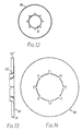
- Fig. 11 is an axial section through a sleeve of the third embodiment;
- Fig. 12 is an end view of the sleeve of Fig. 11,
- Figs. 13 and 14 are side and front views of an end plate of the sleeve; and
- Fig. 15 is a detail from Fig. 11 on a larger scale.
- All of the illustrated embodiments have an
inner sleeve 10 which, in use, contacts a printing roll core. Thisinner sleeve 10 may be identical to a sleeve as disclosed in GB 1,581,232, except that, of course, it is not provided with printing means such as a rubber layer. Thus, theinner sleeve 10 may be formed from a fibre- reinforced resin such as a glass reinforced polyester or glass reinforced epoxy resin which has been laid-up on a former having a desired taper, to a depth of about 1.5 mm. It is allowed to harden to form the seamlessinner sleeve 10. Its outer (cylindrical) surface may have the same shape as the former (i.e. slightly tapered), or it may be ground to form a parallel cylinder. - Referring now to Fig. 1, the first illustrated embodiment has the form of a thick walled tube, whose inside and outside are defined by the
inner sleeve 10 and anouter sleeve 12 which may also be of glass fibre. The outer surface may be ground to facilitate mounting of the printing means (which may be of rubber, aluminium or copper depending on whether the printing process is to be flexography, lithography, or gravure printing). In Fig. 1, the thicknesses of thesleeves inner sleeve 10 may have a thickness of about 1.5 mm, and a diameter of about 140 mm (tapering by about 5 parts in 20,000 over a length of about 500 mm). Theouter sleeve 12 may be rather thicker than theinner sleeve 10. - An
annular layer 14 of a compressible plastics foam (e.g. a closed cell polyethene) is secured to the outer surface of theinner sleeve 10. Anouter layer 16 of greater radial extent is secured to the outer surface of theinner layer 14, and has theouter sleeve 12 secured on its outer surface. The secondannular layer 16 is of rigid foam (e.g. a closed cell polyurethane). - A second embodiment of the invention will now be described with reference to Figs. 2 to 8 of the drawings. This may have at least an
inner sleeve 10 as described in connection with the first embodiment. But outwardly of this, there is not, or need not be, a solid body. There are a multiplicity ofannular discs 18 located along the axis. Each disc has, from its radially inner edge, a plurality of cut-outs 20 so thattongue portions 22 are defined between adjacent cut-outs 20. If thedisc 18 were. planar, thetongues 22 would extend inwardly beyond theinner sleeve 10. But, at least in use, the tongues are bent out of the radial plane, as may be seen in Fig. 5. The material and shaping of thedisc 18 is such that it can be threaded over theinner sleeve 10 so as to contact it with itsbent tongue portions 22, which are resiliently deformable. Suitably, the disc is of sheet metal, such as light alloy sheeting. It can thus be produced in flat form, and the tongue portions can then be bent as required. In Fig. 2, a single tongue portion 22' is shown in its unbent original state. - The outer edge of the
disc 18 has a multiplicity ofradial slots 24, as is best seen in Fig. 4. Thediscs 18 are arranged on theinner sleeve 10 so that the slots of all the discs are aligned. A multiplicity of elongate L-section slats 26 equal in number to the number ofslots 24 in each disc are located so that onearm 30 is within an aligned set ofslits 24, whereas theother arm 28 overlies the outer edge of thediscs 18. Eachslat 26 extends over the whole axial length of the sleeve. The endsdiscs 18 both have inwardly directedtongues 22, and are soared totabs 34 of theslots 26. - The
slats 26 may be produced from sheet metal stampings, as shown in Fig. 7. Thus, a stamping has two generally rectangular elongate portions which will definerespective arms intermediate piece 32 which is of slightly shorter longitudinal extent than thearm 30, which in turn is rather shorter than thearm 28. Thus thearm 28 has arespective tab portion 34 at either end. When the blank is bent to form theslat 26, thetabs 34 are bent over at right-angles so that they lie in radial planes, and serve to hold the assembly together. Thearm portions 30 are preferably given a slight curvature so that, as may be seen in Fig. 2, they define a reasonably smooth cylindrical surface. Thearm 28 may have a multiplicity of transverse slots 36 which, in use, extend radially and embracerespective discs 18 radially inwardly of the ends of theslots 24. This assists in locating the components positively. - Fig. 6 shows a press-
tool 40 for use in bending thetongue portions 22 of ametal disc 18. - The
discs 18 may be secured to theinner sleeve 10, preferably when it is mounted on its former or mandrel, for example using the GRP resin or other suitable adhesive. - In use, printing means are mounted on the outer cylindrical surface of the assembly. Sometimes, it may be possible to mount these directly on the cylindrical surface defined by the
curved legs 20 of theslats 26. However, it will usually be preferable to provide anouter sleeve 12, which may be laid-up on thelegs 30. It may then be ground to form an accurately parallel printing roll. - Under some conditions, the surface defined by the
slats 26 is insufficiently smooth owing to axially extending gaps or discontinuities between adjacent slats. This problem is overcome by the third embodiment, shown in Figs. 9 to 15. This can be regarded as a development of the second embodiment in which eachdisc 18 has an axially extending outer portion around its whole perimeter, like the wall of a cup. Thus when the modified discs or cups are assembled together, they define an outer cylindrical surface, devoid of axially extending gaps, and without the need for separate slats. - Referring to Figs. 9 and 10, a
cup 70 has a radially inner portion that may be just the same as the corresponding portion of adisc 18 of the second embodiment. Thus, there are cut-outs 20 definingtongue portions 22 which curve out of the plane of the disc portion 18' but the radially outer portion of the disc portion 18' does not terminate in a slotted edge. Instead, as can be seen best from Fig. 9, it is continuous with anaxial wall portion 72, which extends in the same axial direction as the projection of thetongues 22. Over most of its axial extent, thewall portion 72 is uniformly cylindrical. But adjacent the disc portion 18', there is astep 74 leading to aspigot portion 76 of slightly reduced diameter. The size of thestep 74 is related to the thickness of the material of which thecup 70 is produced, so that, as will be described later, thespigot portion 76 of onecup 70 is receivable within themouth 78 of another. - A
cup 70 may be produced from a disc of metal, suitably aluminium, by a series of forming operations. The central aperture and the cut-out 20 may be produced first, and thetongues 22 are then turned out of the radial plane so that their inner portions can lie on the cylindrical surface of aninner sleeve 10. An outer edge portion of the disc is then turned over (by spinning) to form a cylindrical surface with astep 74 and reduced-diameter spigot portion 76. - In use, a multiplicity of
cups 70 are fed onto aninner sleeve 10, and may be secured in place e.g. by an epoxy resin. As may be seen from Fig. 11, all of thecups 70 face the same way, and thespigot portion 76 of one is received within themouth 78 of its neighbour. Slight adjustment of the length of the sleeve can be accommodated by adjusting the extent to which the spigots are so received. When thecups 70 have been properly mounted on thesleeve 10, theopen mouth 78 of thefinal cup 70 is closed by mounting anend member 80 on thesleeve 10. - As shown in Figs. 13 and 14, an
end member 80 is essentially identical to acup 70, except that the axial wall portion 72' is much shorter, having only aspigot portion 76. Theend member 80 is mounted in the opposite orientation to theordinary cups 70, that is, itstongue portions 22 and axial wall 72' are opposed to those of thecup 70 with which it engages (and to those of all the other cups too). - In some printing processes, the printing rolls are at least partly immersed in liquids. To prevent the roll assemblies from filling with liquid, the ends of the roll may be closed by discs. Of course, such closures may be desirable even when different printing techniques are being employed. Details of an end disc assembly are shown in Fig. 15. A
closure disc 82 is secured byrivets 84 to the disc portion 18' of theend cup 70. Theclosure disc 82 is annular, its inner margin being very slightly spaced from the cylindrical surface of theinner sleeve 10, so as to allow for the very slight expansion of the inner sleeve when it is being mounted on a printing roll. Thedisc 82 is sealed to thesleeve 10 by a sealant fillet, suitably of a silicone material, which is sufficiently flexible to allow said movement. The outer region of thedisc 82 is similarly sealed to an outer region of thecup 70. - At the other end of the roll, the
end member 80 is fitted with alike closure disc 82. - The assembly of
cups 70 is generally provided with a rubberouter layer 86. This may be cured in position, after dipping in a rubber solution. Alternatively, it may. be a sheet, or may be a spirally wound strip. In use, a rubber stereotype is then attached to therubber layer 86. As may be seen in Fig. 15, theclosure disc 82 extends outwardly as far as therubber layer 86, and is sealed thereto. - The
rubber layer 86 on a sleeve may be stripped off and replaced by one of a different thickness, thus changing slightly the repeat length of the printing roll. - It will be appreciated that various of the features described in connection with particular embodiments may be more widely applicable. For example, the use of different thicknesses of rubber outer layers for minor variations in repeat length is very widely applicable.
Claims (10)
Priority Applications (1)
| Application Number | Priority Date | Filing Date | Title |
|---|---|---|---|
| AT84303028T ATE41360T1 (en) | 1983-05-05 | 1984-05-04 | PRESSURE CYLINDER WITH REMOVABLE JACKET. |
Applications Claiming Priority (2)
| Application Number | Priority Date | Filing Date | Title |
|---|---|---|---|
| GB8312384 | 1983-05-05 | ||
| GB838312384A GB8312384D0 (en) | 1983-05-05 | 1983-05-05 | Printing roll with detachable sleeve |
Publications (3)
| Publication Number | Publication Date |
|---|---|
| EP0127953A2 true EP0127953A2 (en) | 1984-12-12 |
| EP0127953A3 EP0127953A3 (en) | 1986-02-12 |
| EP0127953B1 EP0127953B1 (en) | 1989-03-15 |
Family
ID=10542248
Family Applications (1)
| Application Number | Title | Priority Date | Filing Date |
|---|---|---|---|
| EP84303028A Expired EP0127953B1 (en) | 1983-05-05 | 1984-05-04 | Improvements in or relating to a printing roll with a detachable sleeve |
Country Status (9)
| Country | Link |
|---|---|
| US (1) | US4583460A (en) |
| EP (1) | EP0127953B1 (en) |
| JP (1) | JPS6040298A (en) |
| AT (1) | ATE41360T1 (en) |
| DE (1) | DE3477160D1 (en) |
| DK (1) | DK225784A (en) |
| GB (1) | GB8312384D0 (en) |
| IE (1) | IE55151B1 (en) |
| NO (1) | NO160982C (en) |
Cited By (7)
| Publication number | Priority date | Publication date | Assignee | Title |
|---|---|---|---|---|
| EP0313511A2 (en) * | 1987-10-21 | 1989-04-26 | ALBERT BAUER KG GRAFISCHE WERKSTÄTTEN (GMBH & CO.) | Flexographic press |
| US6647879B1 (en) | 2002-12-26 | 2003-11-18 | Paper Converting Machine Co. | Bridge sleeve for printing apparatus |
| WO2007068262A1 (en) * | 2005-12-12 | 2007-06-21 | Peter Weber | Method for manufacturing and/or recycling of cores for gravure printing cylinders, cores and device for manufacturing the cores |
| NL1033483C2 (en) | 2007-03-02 | 2008-09-03 | Drent Holding B V | Printing cylinder for offset printing machine, has several cups each having conical surface which partially bears against adjacent cup to form connection between the cups |
| NL1033484C2 (en) | 2007-03-02 | 2008-09-03 | Drent Holding B V | Printing cylinder or printing sleeve with insert. |
| WO2008108631A1 (en) * | 2007-03-02 | 2008-09-12 | Drent Holding B.V. | Printing cylinder or printing sleeve, cup and method for producing a printing cylinder or printing sleeve |
| NL2003101C2 (en) * | 2009-06-29 | 2010-12-30 | Drent Holding B V | PRESSURE CYLINDER, OR PRESSURE CYLINDER HOSE AND METHOD FOR MANUFACTURING IT. |
Families Citing this family (25)
| Publication number | Priority date | Publication date | Assignee | Title |
|---|---|---|---|---|
| DE8531065U1 (en) * | 1985-11-02 | 1986-11-13 | Ramisch Kleinewefers Gmbh, 4150 Krefeld, De | |
| JPS62224356A (en) * | 1986-03-26 | 1987-10-02 | 太平化学産業株式会社 | Living body hard tissue prosthetic material and its production |
| JPS6393851A (en) * | 1986-10-08 | 1988-04-25 | Advance Co Ltd | Manufacture of hydroxyapatite-coated material |
| US4838982A (en) * | 1987-06-26 | 1989-06-13 | H.G. Weber & Co., Inc. | Patch applicator vacuum cylinder for web material |
| JPH021285A (en) * | 1988-01-11 | 1990-01-05 | Asahi Optical Co Ltd | Fixable dental and medical granular bone filler, fixing method thereof and bone prosthetic material |
| IT1275901B1 (en) * | 1995-03-14 | 1997-10-24 | Rossini Erminio Spa | DOUBLE CONCENTRIC SLEEVE FOR ROTARY PRINT CYLINDER |
| DE19616756A1 (en) * | 1995-06-05 | 1996-12-12 | Heidelberger Druckmasch Ag | Rotating cylindrical body with low inertia |
| DE29518150U1 (en) * | 1995-07-10 | 1996-01-11 | Polywest Kunststofftechnik | Seamless printing sleeve, especially for a flexographic printing cylinder |
| US5797322A (en) * | 1996-01-31 | 1998-08-25 | Polywest Kunstofftechnik, Sauressig & Partner Gmbh & Co. Kg | Printing sleeve for a flexographic or gravure printing roll |
| US5819657A (en) * | 1996-03-11 | 1998-10-13 | Ermino Rossini, Spa | Air carrier spacer sleeve for a printing cylinder |
| JP3400740B2 (en) * | 1999-04-13 | 2003-04-28 | 東芝セラミックス株式会社 | Calcium phosphate porous sintered body and method for producing the same |
| US6360662B1 (en) | 2000-03-17 | 2002-03-26 | Day International, Inc. | Bridge mandrel for flexographic printing systems |
| US6276271B1 (en) | 2000-03-17 | 2001-08-21 | Day International, Inc. | Bridge mandrel for flexographic printing systems |
| US6713420B2 (en) | 2000-10-13 | 2004-03-30 | Toshiba Ceramics Co., Ltd. | Porous ceramics body for in vivo or in vitro use |
| US6703095B2 (en) * | 2002-02-19 | 2004-03-09 | Day International, Inc. | Thin-walled reinforced sleeve with integral compressible layer |
| US20100307356A1 (en) * | 2008-02-04 | 2010-12-09 | Felice Rossini | Bridged sleeve/cylinder and method of making same for web offset printing machines |
| FR2930767B1 (en) * | 2008-04-30 | 2011-05-13 | Goss Int Montataire Sa | SHEET TRANSPORT CYLINDER, TRANSPORT DEVICE PRESS PRESS AND USE THEREOF |
| FR2930768B1 (en) * | 2008-04-30 | 2011-07-15 | Goss Int Montataire Sa | DEVICE FOR DELIVERING A FLAT SUBSTRATE WITH A CLEANING DEVICE, CUTTING DEVICE, PRESS PRESS AND USE THEREOF |
| US9126395B2 (en) | 2012-04-30 | 2015-09-08 | Rossini S.P.A. | Bridge sleeves with diametrically expandable stabilizers |
| US9120302B2 (en) | 2012-04-30 | 2015-09-01 | Rossini S.P.A. | Bridge sleeves with diametrically expandable stabilizers |
| WO2017116669A1 (en) | 2015-12-28 | 2017-07-06 | The Procter & Gamble Company | Method and apparatus for applying a material onto articles using a transfer component that deflects on both sides |
| CN108472971A (en) * | 2015-12-28 | 2018-08-31 | 宝洁公司 | Three-dimensional article with material for transfer thereon |
| US11141995B2 (en) | 2015-12-28 | 2021-10-12 | The Procter & Gamble Company | Method and apparatus for applying a material onto articles with a pre-distorted transfer component |
| CN111546762B (en) | 2019-02-12 | 2022-04-19 | 宝洁公司 | Method and apparatus for applying material to articles using a transfer member |
| US11752792B2 (en) | 2020-03-09 | 2023-09-12 | The Procter & Gamble Company | Method and apparatus for applying a material onto articles using a transfer component |
Citations (6)
| Publication number | Priority date | Publication date | Assignee | Title |
|---|---|---|---|---|
| DE1536999A1 (en) * | 1966-08-05 | 1970-02-05 | Wilhelm Meyer | Metal pressure roller |
| DE1761519A1 (en) * | 1968-05-30 | 1971-07-01 | Ernst Dunkel Kg | Printing roller (format cylinder) |
| GB1530504A (en) * | 1976-05-06 | 1978-11-01 | Mosstype Corp | Carrier sleeve for printing cylinder |
| EP0000410A1 (en) * | 1977-07-11 | 1979-01-24 | Ab Tetra Pak | Rotary printing cylinder |
| GB1581232A (en) * | 1976-01-08 | 1980-12-10 | Drg Uk Ltd | Printing roll with detachable sleeve and method of fitting that sleeve |
| GB2051681A (en) * | 1979-06-25 | 1981-01-21 | Drg Ltd | Printing rolls |
Family Cites Families (11)
| Publication number | Priority date | Publication date | Assignee | Title |
|---|---|---|---|---|
| US427366A (en) * | 1890-05-06 | Ments | ||
| US615906A (en) * | 1898-12-13 | Buffing and polishing roll or tool | ||
| US724083A (en) * | 1902-06-19 | 1903-03-31 | Daniel C Chandler | Roll for plaiting-machines. |
| US797166A (en) * | 1905-03-13 | 1905-08-15 | John W Anderson | Driving-cylinder for spinning-machines. |
| US973599A (en) * | 1909-04-03 | 1910-10-25 | Lyman A Wheat | Double-line rotary press. |
| US1553352A (en) * | 1924-06-11 | 1925-09-15 | Eugene C Amidon | Embossing roller |
| US1572233A (en) * | 1924-07-21 | 1926-02-09 | Eastman Kodak Co | Resilient-type-disk numbering stamp for photographic-printing machines |
| US2450727A (en) * | 1946-01-22 | 1948-10-05 | Fred L Haushalter | Method of resiliently mounting a roll on a shaft |
| US2556511A (en) * | 1949-04-21 | 1951-06-12 | Earl H Affolter | Process for make-ready |
| US3639959A (en) * | 1970-03-23 | 1972-02-08 | Armstrong Cork Co | Glass fiber cord rubber roller |
| IN146438B (en) * | 1976-01-08 | 1979-06-02 | Strachan & Henshaw Ltd |
-
1983
- 1983-05-05 GB GB838312384A patent/GB8312384D0/en active Pending
-
1984
- 1984-05-04 NO NO841783A patent/NO160982C/en unknown
- 1984-05-04 AT AT84303028T patent/ATE41360T1/en not_active IP Right Cessation
- 1984-05-04 EP EP84303028A patent/EP0127953B1/en not_active Expired
- 1984-05-04 DE DE8484303028T patent/DE3477160D1/en not_active Expired
- 1984-05-04 US US06/607,031 patent/US4583460A/en not_active Expired - Fee Related
- 1984-05-04 IE IE1104/84A patent/IE55151B1/en unknown
- 1984-05-07 DK DK225784A patent/DK225784A/en not_active Application Discontinuation
- 1984-05-07 JP JP59089582A patent/JPS6040298A/en active Pending
Patent Citations (6)
| Publication number | Priority date | Publication date | Assignee | Title |
|---|---|---|---|---|
| DE1536999A1 (en) * | 1966-08-05 | 1970-02-05 | Wilhelm Meyer | Metal pressure roller |
| DE1761519A1 (en) * | 1968-05-30 | 1971-07-01 | Ernst Dunkel Kg | Printing roller (format cylinder) |
| GB1581232A (en) * | 1976-01-08 | 1980-12-10 | Drg Uk Ltd | Printing roll with detachable sleeve and method of fitting that sleeve |
| GB1530504A (en) * | 1976-05-06 | 1978-11-01 | Mosstype Corp | Carrier sleeve for printing cylinder |
| EP0000410A1 (en) * | 1977-07-11 | 1979-01-24 | Ab Tetra Pak | Rotary printing cylinder |
| GB2051681A (en) * | 1979-06-25 | 1981-01-21 | Drg Ltd | Printing rolls |
Cited By (11)
| Publication number | Priority date | Publication date | Assignee | Title |
|---|---|---|---|---|
| EP0313511A2 (en) * | 1987-10-21 | 1989-04-26 | ALBERT BAUER KG GRAFISCHE WERKSTÄTTEN (GMBH & CO.) | Flexographic press |
| DE3735662A1 (en) * | 1987-10-21 | 1989-05-03 | Bauer Albert Grafische | FLEXO PRINTING MACHINE |
| EP0313511A3 (en) * | 1987-10-21 | 1990-06-06 | ALBERT BAUER KG GRAFISCHE WERKSTÄTTEN (GMBH & CO.) | Flexographic press |
| US6647879B1 (en) | 2002-12-26 | 2003-11-18 | Paper Converting Machine Co. | Bridge sleeve for printing apparatus |
| WO2007068262A1 (en) * | 2005-12-12 | 2007-06-21 | Peter Weber | Method for manufacturing and/or recycling of cores for gravure printing cylinders, cores and device for manufacturing the cores |
| NL1033483C2 (en) | 2007-03-02 | 2008-09-03 | Drent Holding B V | Printing cylinder for offset printing machine, has several cups each having conical surface which partially bears against adjacent cup to form connection between the cups |
| NL1033484C2 (en) | 2007-03-02 | 2008-09-03 | Drent Holding B V | Printing cylinder or printing sleeve with insert. |
| WO2008108631A1 (en) * | 2007-03-02 | 2008-09-12 | Drent Holding B.V. | Printing cylinder or printing sleeve, cup and method for producing a printing cylinder or printing sleeve |
| US8312810B2 (en) | 2007-03-02 | 2012-11-20 | Mueller Martini Druckmaschinen Gmbh | Printing cylinder or printing sleeve, cup and method for producing a printing cylinder or printing sleeve |
| NL2003101C2 (en) * | 2009-06-29 | 2010-12-30 | Drent Holding B V | PRESSURE CYLINDER, OR PRESSURE CYLINDER HOSE AND METHOD FOR MANUFACTURING IT. |
| EP2269822A1 (en) | 2009-06-29 | 2011-01-05 | Müller Martini Druckmaschinen Gmbh | Printing cylinder or printing sleeve and process of manufacturing thereof |
Also Published As
| Publication number | Publication date |
|---|---|
| DK225784A (en) | 1984-11-06 |
| JPS6040298A (en) | 1985-03-02 |
| GB8312384D0 (en) | 1983-06-08 |
| US4583460A (en) | 1986-04-22 |
| ATE41360T1 (en) | 1989-04-15 |
| DK225784D0 (en) | 1984-05-07 |
| NO160982C (en) | 1989-06-21 |
| NO841783L (en) | 1984-11-06 |
| IE55151B1 (en) | 1990-06-06 |
| EP0127953A3 (en) | 1986-02-12 |
| EP0127953B1 (en) | 1989-03-15 |
| NO160982B (en) | 1989-03-13 |
| DE3477160D1 (en) | 1989-04-20 |
| IE841104L (en) | 1984-11-05 |
Similar Documents
| Publication | Publication Date | Title |
|---|---|---|
| EP0127953B1 (en) | Improvements in or relating to a printing roll with a detachable sleeve | |
| US4144812A (en) | Printing sleeves | |
| US6042048A (en) | Core for winding a web of deformable material | |
| EP0732201B1 (en) | Concentric double sleeve for a rotary printing cylinder | |
| US3750250A (en) | Printer{40 s roller and method of making same | |
| US5974973A (en) | Base carrier sleeve for rotary printing machines | |
| CN103153622B (en) | Version assembly and disassembly methods is used in version assembling device and printing | |
| GB2042140A (en) | Cartridge cases | |
| HU9402023D0 (en) | Container with loading place and method for producing thereof | |
| US4229028A (en) | Pipe coupler | |
| US4372905A (en) | Method of forming a pipe socket | |
| US4263249A (en) | Method for producing reinforced plastic tubular body having annular grooves, and mold therefor | |
| US4299022A (en) | Method of making transport drum | |
| AU775524B2 (en) | Core end plug for sheet roll material | |
| CA1115125A (en) | Printing sleeve | |
| GB1581232A (en) | Printing roll with detachable sleeve and method of fitting that sleeve | |
| JP4309395B2 (en) | Printing blanket device for printing blanket cylinder and manufacturing method of printing blanket device | |
| EP0042595B1 (en) | Ink roller and method of making same | |
| JP2001031329A (en) | Paper tube | |
| JPH0776466A (en) | Tape winding hub device | |
| US4260168A (en) | Sealing ring | |
| US5210920A (en) | Apparatus and method for precision assembly of photoreceptor drums | |
| KR102559420B1 (en) | Apparatus for forming air-spring | |
| CN217484541U (en) | Tail fiber type grating reflector | |
| KR102553111B1 (en) | Method for forming air-spring |
Legal Events
| Date | Code | Title | Description |
|---|---|---|---|
| PUAI | Public reference made under article 153(3) epc to a published international application that has entered the european phase |
Free format text: ORIGINAL CODE: 0009012 |
|
| AK | Designated contracting states |
Designated state(s): AT BE CH DE FR GB IT LI NL SE |
|
| PUAL | Search report despatched |
Free format text: ORIGINAL CODE: 0009013 |
|
| AK | Designated contracting states |
Designated state(s): AT BE CH DE FR GB IT LI NL SE |
|
| 17P | Request for examination filed |
Effective date: 19860707 |
|
| 17Q | First examination report despatched |
Effective date: 19880226 |
|
| GRAA | (expected) grant |
Free format text: ORIGINAL CODE: 0009210 |
|
| AK | Designated contracting states |
Kind code of ref document: B1 Designated state(s): AT BE CH DE FR GB IT LI NL SE |
|
| REF | Corresponds to: |
Ref document number: 41360 Country of ref document: AT Date of ref document: 19890415 Kind code of ref document: T |
|
| REF | Corresponds to: |
Ref document number: 3477160 Country of ref document: DE Date of ref document: 19890420 |
|
| ITF | It: translation for a ep patent filed |
Owner name: MODIANO & ASSOCIATI S.R.L. |
|
| ET | Fr: translation filed | ||
| PLBE | No opposition filed within time limit |
Free format text: ORIGINAL CODE: 0009261 |
|
| STAA | Information on the status of an ep patent application or granted ep patent |
Free format text: STATUS: NO OPPOSITION FILED WITHIN TIME LIMIT |
|
| 26N | No opposition filed | ||
| PGFP | Annual fee paid to national office [announced via postgrant information from national office to epo] |
Ref country code: GB Payment date: 19900424 Year of fee payment: 7 |
|
| PGFP | Annual fee paid to national office [announced via postgrant information from national office to epo] |
Ref country code: FR Payment date: 19900518 Year of fee payment: 7 |
|
| PGFP | Annual fee paid to national office [announced via postgrant information from national office to epo] |
Ref country code: SE Payment date: 19900522 Year of fee payment: 7 Ref country code: CH Payment date: 19900522 Year of fee payment: 7 |
|
| PGFP | Annual fee paid to national office [announced via postgrant information from national office to epo] |
Ref country code: BE Payment date: 19900523 Year of fee payment: 7 |
|
| PGFP | Annual fee paid to national office [announced via postgrant information from national office to epo] |
Ref country code: DE Payment date: 19900525 Year of fee payment: 7 Ref country code: AT Payment date: 19900525 Year of fee payment: 7 |
|
| ITTA | It: last paid annual fee | ||
| PGFP | Annual fee paid to national office [announced via postgrant information from national office to epo] |
Ref country code: NL Payment date: 19900531 Year of fee payment: 7 |
|
| REG | Reference to a national code |
Ref country code: CH Ref legal event code: PUE Owner name: STRACHAN HENSHAW MACHINERY LIMITED |
|
| PG25 | Lapsed in a contracting state [announced via postgrant information from national office to epo] |
Ref country code: GB Effective date: 19910504 Ref country code: AT Effective date: 19910504 |
|
| PG25 | Lapsed in a contracting state [announced via postgrant information from national office to epo] |
Ref country code: SE Effective date: 19910505 |
|
| PG25 | Lapsed in a contracting state [announced via postgrant information from national office to epo] |
Ref country code: LI Effective date: 19910531 Ref country code: CH Effective date: 19910531 Ref country code: BE Effective date: 19910531 |
|
| ITPR | It: changes in ownership of a european patent |
Owner name: CESSIONE;STRACHAN HENSHAW MACHINERY LIMITED |
|
| NLS | Nl: assignments of ep-patents |
Owner name: STRACHAN HENSHAW MACHINERY LIMITED TE BRISTOL, GRO |
|
| REG | Reference to a national code |
Ref country code: FR Ref legal event code: TP |
|
| BERE | Be: lapsed |
Owner name: STRACHAN HENSHAW MACHINERY LTD Effective date: 19910531 |
|
| PG25 | Lapsed in a contracting state [announced via postgrant information from national office to epo] |
Ref country code: NL Effective date: 19911201 |
|
| REG | Reference to a national code |
Ref country code: GB Ref legal event code: 732 |
|
| GBPC | Gb: european patent ceased through non-payment of renewal fee | ||
| NLV4 | Nl: lapsed or anulled due to non-payment of the annual fee | ||
| PG25 | Lapsed in a contracting state [announced via postgrant information from national office to epo] |
Ref country code: FR Effective date: 19920131 |
|
| REG | Reference to a national code |
Ref country code: CH Ref legal event code: PL |
|
| PG25 | Lapsed in a contracting state [announced via postgrant information from national office to epo] |
Ref country code: DE Effective date: 19920303 |
|
| REG | Reference to a national code |
Ref country code: FR Ref legal event code: ST |
|
| EUG | Se: european patent has lapsed |
Ref document number: 84303028.9 Effective date: 19911209 |