EP0130649B1 - Signal generating device - Google Patents
Signal generating device Download PDFInfo
- Publication number
- EP0130649B1 EP0130649B1 EP84200938A EP84200938A EP0130649B1 EP 0130649 B1 EP0130649 B1 EP 0130649B1 EP 84200938 A EP84200938 A EP 84200938A EP 84200938 A EP84200938 A EP 84200938A EP 0130649 B1 EP0130649 B1 EP 0130649B1
- Authority
- EP
- European Patent Office
- Prior art keywords
- sleeve
- signal generating
- generating device
- movement
- actuating part
- Prior art date
- Legal status (The legal status is an assumption and is not a legal conclusion. Google has not performed a legal analysis and makes no representation as to the accuracy of the status listed.)
- Expired
Links
Images

Classifications
-
- G—PHYSICS
- G06—COMPUTING; CALCULATING OR COUNTING
- G06F—ELECTRIC DIGITAL DATA PROCESSING
- G06F3/00—Input arrangements for transferring data to be processed into a form capable of being handled by the computer; Output arrangements for transferring data from processing unit to output unit, e.g. interface arrangements
- G06F3/01—Input arrangements or combined input and output arrangements for interaction between user and computer
- G06F3/03—Arrangements for converting the position or the displacement of a member into a coded form
- G06F3/041—Digitisers, e.g. for touch screens or touch pads, characterised by the transducing means
- G06F3/042—Digitisers, e.g. for touch screens or touch pads, characterised by the transducing means by opto-electronic means
-
- G—PHYSICS
- G06—COMPUTING; CALCULATING OR COUNTING
- G06F—ELECTRIC DIGITAL DATA PROCESSING
- G06F3/00—Input arrangements for transferring data to be processed into a form capable of being handled by the computer; Output arrangements for transferring data from processing unit to output unit, e.g. interface arrangements
- G06F3/01—Input arrangements or combined input and output arrangements for interaction between user and computer
- G06F3/02—Input arrangements using manually operated switches, e.g. using keyboards or dials
- G06F3/0202—Constructional details or processes of manufacture of the input device
- G06F3/021—Arrangements integrating additional peripherals in a keyboard, e.g. card or barcode reader, optical scanner
- G06F3/0213—Arrangements providing an integrated pointing device in a keyboard, e.g. trackball, mini-joystick
-
- G—PHYSICS
- G06—COMPUTING; CALCULATING OR COUNTING
- G06F—ELECTRIC DIGITAL DATA PROCESSING
- G06F3/00—Input arrangements for transferring data to be processed into a form capable of being handled by the computer; Output arrangements for transferring data from processing unit to output unit, e.g. interface arrangements
- G06F3/01—Input arrangements or combined input and output arrangements for interaction between user and computer
- G06F3/03—Arrangements for converting the position or the displacement of a member into a coded form
- G06F3/033—Pointing devices displaced or positioned by the user, e.g. mice, trackballs, pens or joysticks; Accessories therefor
- G06F3/0354—Pointing devices displaced or positioned by the user, e.g. mice, trackballs, pens or joysticks; Accessories therefor with detection of 2D relative movements between the device, or an operating part thereof, and a plane or surface, e.g. 2D mice, trackballs, pens or pucks
- G06F3/03548—Sliders, in which the moving part moves in a plane
-
- Y—GENERAL TAGGING OF NEW TECHNOLOGICAL DEVELOPMENTS; GENERAL TAGGING OF CROSS-SECTIONAL TECHNOLOGIES SPANNING OVER SEVERAL SECTIONS OF THE IPC; TECHNICAL SUBJECTS COVERED BY FORMER USPC CROSS-REFERENCE ART COLLECTIONS [XRACs] AND DIGESTS
- Y10—TECHNICAL SUBJECTS COVERED BY FORMER USPC
- Y10T—TECHNICAL SUBJECTS COVERED BY FORMER US CLASSIFICATION
- Y10T74/00—Machine element or mechanism
- Y10T74/20—Control lever and linkage systems
- Y10T74/20012—Multiple controlled elements
- Y10T74/20201—Control moves in two planes
Definitions
- This invention relates to manually operable signal generating devices of a type suitable for use as interface devices for generating control signals which can be used to control movement of at least one discrete image portion in a display which is produced on the screen of a display device, for instance a television monitor.
- a known signal generating device of the above type is the roller- or tracker-ball, commonly referred to as a "mouse". Examples of such a “mouse” device may be found in US Patents 3 304 434; 3 541 541; 3 835 464; 3 892 963 and 3 987 685.
- This known device of the above type can generate control signals for controlling movement of a discrete image portion such that the latter can be positioned anywhere in the display by appropriate manual manipulation of the device.
- the control signals generated by the device can be considered to be co-ordinate control signals which represent the co-ordinates of any selected position in the display and which are used to drive display circuits to control the movement of the image portion from its current position in the display to the selected position.
- a manually operable signal generating device of the type specified above comprises an actuating part which is movable by finger pressure to any position within a substantially plane window area, said actuating part being provided on a continuous loop member at least parts of which are flexible such as to be disposed about spaced- apart parallel guide surfaces to allow composite movement of the member along and around said guide surfaces in response to finger pressure applied to said actuating part, the device further comprising signal means responsive to said composite movement to generate said control signals.
- a signal device By having an actuating part which only requires finger pressure to move it a signal device according to the invention is simpler and more convenient to use compared with the previously known devices which are operated using the entire hand.
- the actuating part is preferably a separate part secured to the loop member, although it could be simply a raised, grooved or otherwise identifiable integral portion of the loop member.
- the actuating part can include a push-button switch. It can then be arranged that this switch is required to be operated to implement different control functions.
- said guide surfaces are formed as curved surfaces at two opposite ends of a generally rectangular support block
- said continuous loop member is a sleeve having flexible portions close fitting about said curved surfaces for sliding reciprocal movement of the sleeve in a first direction normal to said curved surfaces and sliding reciprocal movement in a second direction parallel to said curved surfaces, the distance between the curved surfaces, and their lengths relative to the width of said flexible portions of the sleeve, as determined by the dimensions of the support block, being such as to permit movement of the sleeve in said first and second directions to an extent appropriate for enabling said actuating part to be moved to any position in the plane window area.
- This particular embodiment of a signal generating device according to the invention can be given a shallow or relatively flat construction by using a support block which is thin compared with its length and width.
- a support block which is thin compared with its length and width.
- the portions (upper and lower) of the sleeve between said flexible portions can be rigid, or a wholly flexible sleeve may be preferable to facilitate maintaining the sleeve in close-fitting relationship with the support block.
- a wholly flexible sleeve is provided, the upper surface of the support block may have a small amount of convex curvature to help keep the sleeve in firm contact against this upper surface.
- the entire sleeve or at least a section thereof can be elasticated.
- the section may comprise an "elastic joint" by which opposite ends of a length of flexible material are joined together to form the sleeve.
- the support block can include tensioning means which is operable to urge against the sleeve to tension it about the block.
- tensioning means may be a spring-loaded bar located in a channel in the support block, the channel extending parallel to said guide surfaces.
- Said signal means are suitably opto-electronic coupling means comprised by two position detectors one for each of said first and second directions of movement, each of which position detectors comprises a light grating moveable with the sleeve with its bars lying normal to the direction of movement to be detected, a pair of light sensitive diodes located at one side of the grating, and a light source located at the other side of the grating, the two diodes of the pair being positioned offset one from the other in the direction concerned, the device further comprising logic circuitry which is responsive to the signal outputs from the two pairs of diodes to produce said control signals.
- each light grating is provided as a series of alternate opaque and translucent strips at the underside of the sleeve, that is at the opposite side to that at which the actuating part is provided.
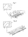
- the display apparatuses shown in Figures 1 and 2 each comprise a television monitor 1 having a display screen 2, and a remote control console 3.
- the control console 3 is assumed to contain microcomputer or video game circuitry which is accessed by a keyboard interface 4.
- a signal generating device 5 is also provided on the control console 3 as a second interface device, a signal generating device 5 in accordance with the invention.
- this device 5 is located at the centre of a sloping panel 6 behind the keyboard interface 4; whereas in Figure 2 it is located at the side of the keyboard interface 4 in the top panel 7.
- the signal generating device 5 has a plane window area 8 which is defined by an aperture in the panel 6 or in the panel 7, as the case may be.
- An actuating knob 9 of the device 5 can be engaged by a finger, as illustrated in Figure 1, so as to be moved by finger pressure to any position within the area 8.
- the movement of the actuating knob 9 is composite movement made up of reciprocal movement in orthogonal directions.
- the movement of the actuating knob 9 results in the production of co-ordinate control signals which represent the co-ordinates of the position of the actuating knob 9 within the area 8.
- These control signals can be used in conventional ways to drive suitable display circuits for determining the position of an image portion 10 of a display on the display screen 2.
- control signals can be produced continually during movement of the actuating knob 9 to control the positioning of a cursor on the display screen, or to control movement of an element of a video game display.
- control signals can be used to control a graphics input onto the display screen 2 in a manner analogous to such control as effected by an electronic "writing tablet”.
- Another possible use is one which is analogous to touch selection of a displayed item as afforded by a touch- sensitive screen which overlays a display screen. For this latter use, a cursor would be moved to a selected position which is then "touch-selected", for instance by operating a push-button switch provided at the end of the actuating knob 9.
- Such a push-button switch can also be used to determine the start and finish of a graphics input.
- the device 5 is extremely compatible for use with a keyboard interface, because it can be operated with very little movement of the hand from a normal typing position.
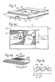
- the particular construction of signal generating device shown in Figure 3 comprises a flexible sleeve 11 which is disposed about a support block 12.
- the block 12 is of generally rectangular shape and has curved surfaces at its two opposite ends 13 and 14.
- the flexible sleeve 11 is close-fitting on the block 12 for sliding reciprocal movement in the direction x, that is for rotational movement around the block 12.
- the block 12 has a greater dimension than the sleeve 11 in the direction y so that the sleeve 11 can also undergo sliding reciprocal movement in the direction y.
- a channel 15 extends along the center of the block 12 in the direction y. This channel 15 accommodates a spring-loaded bar 16 for tensioning the sleeve 11 in its close-fitting relationship with the support block 12.
- the friction between the sleeve 11 and the support block 12 is kept low so that the sleeve slides very easily over the block.
- the upper "flat" surface of the block 12 may have a small amount of convex curvature to help keep the sleeve 11 in firm contact against this upper surface.
- the sleeve 11 and block 12 are made of a plastics material, such as PVC, having a relatively low coefficient of friction.
- the sleeve 11 may alternatively be made of strong reinforced paper. If the block 12 is itself made of a compressible material, then the sleeve 11 may be fitted tightly onto the block by slightly compressing the latter. The spring-loaded bar 16 can then be dispensed with.
- the entire sleeve 11 or at least a section thereof can be elasticated.
- the section may comprise an "elastic joint" by which opposite ends of a length of flexible material are joined together to form the sleeve 11.
- a plate 17 which corresponds to either of the panels 6 and 7 (Figs. 1 and 2) and which defines a plane window area 18.
- An actuating knob 19, which is secured to the sleeve 11, is disposed within the area 18 and can be moved by applied finger pressure to any position within that area.
- the knob 19 can be moved in the direction x over a length /, and in the direction y over a length w, and corresponding movement of the sleeve 11 will be effected.
- this composite movement of the sleeve 11 can be detected by means of suitable detector means to produce control signals indicative of such movement.
- a push-button switch 20 is provided on the knob 19 for the possible uses discussed previously.
- the sleeve is given a width just greater than twice the width w of the area 18 (i.e. in the direction y).
- the block 12 is then required to have a dimension of approximately three times the width w in the same direction y.
- the aspect ratio of the window area 18 is nominally that of the controlled display, which for a normal television screen is 4/3.
- the signal generating device includes two position detectors (not shown in Figure 3) for detecting movement of the knob 19 in the directions x and y, respectively.
- Each of these two position detectors is located at the underside of the device, that is at the side remote from the window area 18, and comprises a light grating formed on the sleeve 11 together with a pair of light sensitive diodes and an associated light source.
- these two position detectors have their diodes recessed into the bar 16 (when provided) and are urged into contact with the respective light grating due to the spring-loading of the bar 16. Otherwise, these diodes would be recessed into the underside of the support block 12. Details of these two position detectors are shown diagrammatically in Figures 4a to 4c.
- Figure 4a shows fragmentary portions of the underside of the flexible sleeve 11 and the support block 12.
- Two light gratings 21 and 22 are formed on the sleeve 11 as a series of alternate opaque and translucent strips.
- the grating 21 is provided in respect of movement in the direction x and has its bars (opaque strips) lying normal to this direction.
- the grating 22 is provided in respect of movement in the direction y and has its bars lying normal to this latter direction.
- Two pairs of photo diodes 23/24 and 25/26 lie at one side of the two light gratings 21 and 22, respectively.
- these pairs of photo diodes receive interrupted light via the relevant grating from an associated light source located at the opposite side of the grating to the diodes.
- the two diodes of each pair are positioned offset one from the other in the direction of movement concerned, so that one diode will produce its signal output before the other.
- Figure 4b illustrates the offset positioning of the two diodes of the diode pair 23/24
- Figure 4c shows the signal outputs S/23 and S/23 with different phases from these two diodes.
- Figure 4b also shows for the diode pair 23/24 a light source 27 which is suitably a light-emitting diode.
- Figure 4b further shows a graticule 28 for the diode pair 23/24.
- the graticule 28 is assumed to have alternate opaque and translucent strips like the grating 21.
- the other position detector having the diode pair 25/ 26 is similarly constituted.
- the position detectors need not include the graticule (28), but then a detector aperture no wider than the width of each bar would be required.
- the provision of the graticule enables higher measurement resolution by using thinner bars.
- the detector aperture (grating) can now be of the same pitch as the light grating bars.
- the offset of the two diodes of each diode pair is suitably one quarter of the bar spacing of the light grating.
- the offset effect can be achieved by providing two graticules such as 28, one for each diode, which are offset one quarter of the bar spacing with respect to each other.
- the cyclic order of the four possible signal output states from the two diodes determines unambiguously the direction of motion.
- Figure 5 shows a logic circuit for ascertaining this cyclic order. This logic circuit, which will be described later, may be implemented in hardware or by software. With such a four-phase position detector a bar spacing in the light grating of as much as 1 mm will give a resolution of 1 part in 250 for 6.25 cm. control travel.
- some resetting means are required to serve as a zeroing sensor for producing a signal when a known "zero" position is reached by the actuating knob (19). This signal can then be used for resetting a position counter, both at the start of an operating session, and periodically throughout it to guard against "lost" pulses.
- the resetting means can be a mechanical switch (not shown) located in the bottom left hand corner of the window area 18 for operation when contacted by the actuating knob (19).
- the resetting means can be two further light-sensitive diodes 29 and 30, one for each direction of motion, which are positioned to detect an opaque border 31 and 32 of the appertaining light grating 21 or 22. In order to ensure initial zeroing, it is necessary to move the actuating knob (19) to the zero position at the start of an operating session.
- position detectors for instance ones which are magnetically operable, may be used.
- the logic circuit shown in Figure 5 is provided in respect of each pair of diodes 23/24 and 25/26 (i.e. one logic circuit for each position detector).
- This logic circuit comprises two threshold detectors 33 and 34, four edge detectors 35 to 38, eight AND-gates 39 to 46, two OR-gates 47 and 48, and an up/down counter 49, connected as shown.
- the threshold detector 33 is connected to receive the signal output from one diode of a pair, say signal output S/23 from diode 23, and the other threshold detector 34 receives the signal output S/ 24 from the other diode 24.
- the two signal outputs S/23 and S/ 24 are shown relative to a time scale t0 to t4, during which they are at either a logic 0 level or a logic 1 level.
- the threshold detectors 33 and 34 determine which logic level prevails at any time, and the edge detectors 35 to 38 detect when changes in the logic levels occur.
- the following Table shows the resultant logic levels at the two inputs a and b of each of the AND-gates 39 to 46 during the instants t0 to t4. The cyclic order of these resultant logic levels determines which of the AND-gates 39 to 46 produce logic 1 outputs which via the OR-gates 47 and 48, are applied to inputs U and D of the counter 49 to step this counter up or down.
- the count position of the counter 49 at outputs Q o to Q N signifies the subsisting position of the actuating knob (19) in the relevant direction.
- a reset input R of the counter 49 is connected to receive a reset or "clear" signal C/29 from the relevant zeroing sensor (29).
- signal output S/23 leads the signal output S/24, thereby indicating that motion in the direction x is "upward” as seen in Figure 4a.
- AND-gates 46, 41, 43 and 40 are opened in turn during the instants t1 to t4, respectively, to apply logic 1 outputs to the input U of the counter 49.
- the threshold detectors are required to have hysteresis to prevent "jitter" in operation.
- the edge detectors are suitably monostable which produce pulses of short width (e.g. 100 ps) compared with the minimum possible width of the pulses produced by the light sensitive diodes.
Description
- This invention relates to manually operable signal generating devices of a type suitable for use as interface devices for generating control signals which can be used to control movement of at least one discrete image portion in a display which is produced on the screen of a display device, for instance a television monitor.
- A known signal generating device of the above type is the roller- or tracker-ball, commonly referred to as a "mouse". Examples of such a "mouse" device may be found in US
Patents 3 304 434; 3 541 541; 3 835 464; 3 892 963 and 3 987 685. This known device of the above type can generate control signals for controlling movement of a discrete image portion such that the latter can be positioned anywhere in the display by appropriate manual manipulation of the device. The control signals generated by the device can be considered to be co-ordinate control signals which represent the co-ordinates of any selected position in the display and which are used to drive display circuits to control the movement of the image portion from its current position in the display to the selected position. - In a computer-based information display system, there are many instances where interactive operation of the system by a user is based on visual feedback from displayed information. It is well-established that the above-mentioned known signal generating devices of the above type can be employed as interface devices to effect such interactive operation, and that the visual feedback from the display to a user obviates the need for the user having to look at such an interface device whilst operating it.
- However, with this known signal generating device of the above type the entire hand rather than a single finger has to be used to operate them, which can be a disadvantage when the device forms part of a user control console containing other types of interface device, for instance a keyboard. In particular, the need to engage the device with the entire hand can restrict the speed at which it can betaken into use. Also, a tracker- or roller-ball is intrinsically large in three dimensions, so that mounting it in a control console can be a problem.
- It is an object of the present invention to provide an improved signal generating device of the type set forth above which does not suffer from these drawbacks.
- According to the invention, a manually operable signal generating device of the type specified above comprises an actuating part which is movable by finger pressure to any position within a substantially plane window area, said actuating part being provided on a continuous loop member at least parts of which are flexible such as to be disposed about spaced- apart parallel guide surfaces to allow composite movement of the member along and around said guide surfaces in response to finger pressure applied to said actuating part, the device further comprising signal means responsive to said composite movement to generate said control signals.
- By having an actuating part which only requires finger pressure to move it a signal device according to the invention is simpler and more convenient to use compared with the previously known devices which are operated using the entire hand.
- In carrying out the invention, the actuating part is preferably a separate part secured to the loop member, although it could be simply a raised, grooved or otherwise identifiable integral portion of the loop member. As a separate part, the actuating part can include a push-button switch. It can then be arranged that this switch is required to be operated to implement different control functions.
- In one particular embodiment of the invention, said guide surfaces are formed as curved surfaces at two opposite ends of a generally rectangular support block, and said continuous loop member is a sleeve having flexible portions close fitting about said curved surfaces for sliding reciprocal movement of the sleeve in a first direction normal to said curved surfaces and sliding reciprocal movement in a second direction parallel to said curved surfaces, the distance between the curved surfaces, and their lengths relative to the width of said flexible portions of the sleeve, as determined by the dimensions of the support block, being such as to permit movement of the sleeve in said first and second directions to an extent appropriate for enabling said actuating part to be moved to any position in the plane window area.
- This particular embodiment of a signal generating device according to the invention can be given a shallow or relatively flat construction by using a support block which is thin compared with its length and width. Such a construction has the advantage that it facilitates the accommodation of the device in a control console.
- The portions (upper and lower) of the sleeve between said flexible portions can be rigid, or a wholly flexible sleeve may be preferable to facilitate maintaining the sleeve in close-fitting relationship with the support block. When a wholly flexible sleeve is provided, the upper surface of the support block may have a small amount of convex curvature to help keep the sleeve in firm contact against this upper surface.
- To facilitate tensioning the sleeve in its close-fitting relationship with the support block, the entire sleeve or at least a section thereof can be elasticated. In the latter case, the section may comprise an "elastic joint" by which opposite ends of a length of flexible material are joined together to form the sleeve.
- Alternatively, the support block can include tensioning means which is operable to urge against the sleeve to tension it about the block. Such tensioning means may be a spring-loaded bar located in a channel in the support block, the channel extending parallel to said guide surfaces.
- Said signal means are suitably opto-electronic coupling means comprised by two position detectors one for each of said first and second directions of movement, each of which position detectors comprises a light grating moveable with the sleeve with its bars lying normal to the direction of movement to be detected, a pair of light sensitive diodes located at one side of the grating, and a light source located at the other side of the grating, the two diodes of the pair being positioned offset one from the other in the direction concerned, the device further comprising logic circuitry which is responsive to the signal outputs from the two pairs of diodes to produce said control signals.
- Conveniently, each light grating is provided as a series of alternate opaque and translucent strips at the underside of the sleeve, that is at the opposite side to that at which the actuating part is provided.
- It is mentioned that the optical detection of movement as applied to a "mouse" device is known from
EP 0 081 348 (A3). - In order that the invention may be more fully understood, reference will now be made by way of example to the accompanying drawings, of which:-
- Figures 1 and 2 show diagrammatically display apparatuses comprising respective forms of control console and an associated display device;
- Figure 3 shows diagrammatically a particular construction of signal generating device according to the-invention;
- Figures 4a to 4c show details of one form of opto-electronic coupler for the device of Figure 3; and
- Figure 5 shows one form of logic circuit for producing control signals from the signal output of the opto-electronic coupler of Figure 4.
- Referring to the drawings, the display apparatuses shown in Figures 1 and 2 each comprise a television monitor 1 having a
display screen 2, and aremote control console 3. Thecontrol console 3 is assumed to contain microcomputer or video game circuitry which is accessed by akeyboard interface 4. There is also provided on thecontrol console 3 as a second interface device, a signal generatingdevice 5 in accordance with the invention. In Figure 1, thisdevice 5 is located at the centre of a sloping panel 6 behind thekeyboard interface 4; whereas in Figure 2 it is located at the side of thekeyboard interface 4 in thetop panel 7. - The signal generating
device 5 has a plane window area 8 which is defined by an aperture in the panel 6 or in thepanel 7, as the case may be. An actuating knob 9 of thedevice 5 can be engaged by a finger, as illustrated in Figure 1, so as to be moved by finger pressure to any position within the area 8. The movement of the actuating knob 9 is composite movement made up of reciprocal movement in orthogonal directions. As will be described presently with reference to Figures 3 to 5, the movement of the actuating knob 9 results in the production of co-ordinate control signals which represent the co-ordinates of the position of the actuating knob 9 within the area 8. These control signals can be used in conventional ways to drive suitable display circuits for determining the position of animage portion 10 of a display on thedisplay screen 2. For instance, the control signals can be produced continually during movement of the actuating knob 9 to control the positioning of a cursor on the display screen, or to control movement of an element of a video game display. Alternatively, the control signals can be used to control a graphics input onto thedisplay screen 2 in a manner analogous to such control as effected by an electronic "writing tablet". Another possible use is one which is analogous to touch selection of a displayed item as afforded by a touch- sensitive screen which overlays a display screen. For this latter use, a cursor would be moved to a selected position which is then "touch-selected", for instance by operating a push-button switch provided at the end of the actuating knob 9. Such a push-button switch can also be used to determine the start and finish of a graphics input. By reason of its single finger operation, thedevice 5 is extremely compatible for use with a keyboard interface, because it can be operated with very little movement of the hand from a normal typing position. - The particular construction of signal generating device shown in Figure 3 comprises a flexible sleeve 11 which is disposed about a
support block 12. Theblock 12 is of generally rectangular shape and has curved surfaces at its twoopposite ends block 12 for sliding reciprocal movement in the direction x, that is for rotational movement around theblock 12. Theblock 12 has a greater dimension than the sleeve 11 in the direction y so that the sleeve 11 can also undergo sliding reciprocal movement in the direction y. Achannel 15 extends along the center of theblock 12 in the direction y. Thischannel 15 accommodates a spring-loadedbar 16 for tensioning the sleeve 11 in its close-fitting relationship with thesupport block 12. However, the friction between the sleeve 11 and thesupport block 12 is kept low so that the sleeve slides very easily over the block. Also, the upper "flat" surface of theblock 12 may have a small amount of convex curvature to help keep the sleeve 11 in firm contact against this upper surface. Conveniently, the sleeve 11 andblock 12 are made of a plastics material, such as PVC, having a relatively low coefficient of friction. The sleeve 11 may alternatively be made of strong reinforced paper. If theblock 12 is itself made of a compressible material, then the sleeve 11 may be fitted tightly onto the block by slightly compressing the latter. The spring-loadedbar 16 can then be dispensed with. As another alternative, which dispenses with the spring-loadedbar 16, the entire sleeve 11 or at least a section thereof can be elasticated. In the latter case, the section may comprise an "elastic joint" by which opposite ends of a length of flexible material are joined together to form the sleeve 11. - There is located above the sleeve/
block combination 12/13, a plate 17 which corresponds to either of the panels 6 and 7 (Figs. 1 and 2) and which defines aplane window area 18. An actuatingknob 19, which is secured to the sleeve 11, is disposed within thearea 18 and can be moved by applied finger pressure to any position within that area. Thus, theknob 19 can be moved in the direction x over a length /, and in the direction y over a length w, and corresponding movement of the sleeve 11 will be effected. As will be described next, this composite movement of the sleeve 11 can be detected by means of suitable detector means to produce control signals indicative of such movement. A push-button switch 20 is provided on theknob 19 for the possible uses discussed previously. In order that the edges of the sleeve 11 are never exposed in thewindow area 18, the sleeve is given a width just greater than twice the width w of the area 18 (i.e. in the direction y). Theblock 12 is then required to have a dimension of approximately three times the width w in the same direction y. The aspect ratio of thewindow area 18 is nominally that of the controlled display, which for a normal television screen is 4/3. - The signal generating device includes two position detectors (not shown in Figure 3) for detecting movement of the
knob 19 in the directions x and y, respectively. Each of these two position detectors is located at the underside of the device, that is at the side remote from thewindow area 18, and comprises a light grating formed on the sleeve 11 together with a pair of light sensitive diodes and an associated light source. Conveniently, these two position detectors have their diodes recessed into the bar 16 (when provided) and are urged into contact with the respective light grating due to the spring-loading of thebar 16. Otherwise, these diodes would be recessed into the underside of thesupport block 12. Details of these two position detectors are shown diagrammatically in Figures 4a to 4c. Figure 4a shows fragmentary portions of the underside of the flexible sleeve 11 and thesupport block 12. Twolight gratings photo diodes 23/24 and 25/26 lie at one side of the twolight gratings diode pair 23/24, and Figure 4c shows the signal outputs S/23 and S/23 with different phases from these two diodes. Figure 4b also shows for thediode pair 23/24 alight source 27 which is suitably a light-emitting diode. Figure 4b further shows a graticule 28 for thediode pair 23/24. The graticule 28 is assumed to have alternate opaque and translucent strips like the grating 21. The other position detector having the diode pair 25/ 26 is similarly constituted. The position detectors need not include the graticule (28), but then a detector aperture no wider than the width of each bar would be required. The provision of the graticule enables higher measurement resolution by using thinner bars. In fact, the detector aperture (grating) can now be of the same pitch as the light grating bars. The offset of the two diodes of each diode pair is suitably one quarter of the bar spacing of the light grating. Alternatively, instead of having the diodes offset, the offset effect can be achieved by providing two graticules such as 28, one for each diode, which are offset one quarter of the bar spacing with respect to each other. The cyclic order of the four possible signal output states from the two diodes then determines unambiguously the direction of motion. Figure 5 shows a logic circuit for ascertaining this cyclic order. This logic circuit, which will be described later, may be implemented in hardware or by software. With such a four-phase position detector a bar spacing in the light grating of as much as 1 mm will give a resolution of 1 part in 250 for 6.25 cm. control travel. Finer resolution then becomes possible by reducing the bar spacing, but whether it would be useful depends on the extent of capability for fine motion control using a fingertip. However, the maximum resolution which is obtainable is probably limited principally by the extent to which the sleeve is subject to "skewing" when moved. The "skewing" can be kept small by locating the two diodes of each pair as close together as possible in the direction normal to the direction in which they sense movement. Any rotation of the light grating bars away from their orthogonal relationship with the relevant direction of movement would upset the phase relationship between the detector components. - Because the signal outputs from the position detectors indicate movement only, some resetting means are required to serve as a zeroing sensor for producing a signal when a known "zero" position is reached by the actuating knob (19). This signal can then be used for resetting a position counter, both at the start of an operating session, and periodically throughout it to guard against "lost" pulses. The resetting means can be a mechanical switch (not shown) located in the bottom left hand corner of the
window area 18 for operation when contacted by the actuating knob (19). Alternatively, as shown in Figure 4a, the resetting means can be two further light-sensitive diodes opaque border - Other forms of position detectors, for instance ones which are magnetically operable, may be used.
- The logic circuit shown in Figure 5 is provided in respect of each pair of
diodes 23/24 and 25/26 (i.e. one logic circuit for each position detector). This logic circuit comprises twothreshold detectors edge detectors 35 to 38, eight AND-gates 39 to 46, two OR-gates counter 49, connected as shown. Thethreshold detector 33 is connected to receive the signal output from one diode of a pair, say signal output S/23 fromdiode 23, and theother threshold detector 34 receives the signal output S/ 24 from theother diode 24. - In Figure 4c, the two signal outputs S/23 and S/ 24 are shown relative to a time scale t0 to t4, during which they are at either a
logic 0 level or a logic 1 level. Thethreshold detectors edge detectors 35 to 38 detect when changes in the logic levels occur. The following Table shows the resultant logic levels at the two inputs a and b of each of the AND-gates 39 to 46 during the instants t0 to t4. The cyclic order of these resultant logic levels determines which of the AND-gates 39 to 46 produce logic 1 outputs which via the OR-gates counter 49 to step this counter up or down. The count position of thecounter 49 at outputs Qo to QN signifies the subsisting position of the actuating knob (19) in the relevant direction. A reset input R of thecounter 49 is connected to receive a reset or "clear" signal C/29 from the relevant zeroing sensor (29). In Figure 4c, signal output S/23 leads the signal output S/24, thereby indicating that motion in the direction x is "upward" as seen in Figure 4a. For this motion, AND-gates counter 49.
- It can be seen from the above Table that a level change at one input and the logic level of the other input gives the sense of movement in the direction concerned. The threshold detectors are required to have hysteresis to prevent "jitter" in operation. The edge detectors are suitably monostable which produce pulses of short width (e.g. 100 ps) compared with the minimum possible width of the pulses produced by the light sensitive diodes.
Claims (14)
Applications Claiming Priority (2)
| Application Number | Priority Date | Filing Date | Title |
|---|---|---|---|
| GB8318103 | 1983-07-04 | ||
| GB08318103A GB2142711A (en) | 1983-07-04 | 1983-07-04 | Manually operable x-y signal generator |
Publications (2)
| Publication Number | Publication Date |
|---|---|
| EP0130649A1 EP0130649A1 (en) | 1985-01-09 |
| EP0130649B1 true EP0130649B1 (en) | 1987-11-04 |
Family
ID=10545217
Family Applications (1)
| Application Number | Title | Priority Date | Filing Date |
|---|---|---|---|
| EP84200938A Expired EP0130649B1 (en) | 1983-07-04 | 1984-06-29 | Signal generating device |
Country Status (8)
| Country | Link |
|---|---|
| US (1) | US4692756A (en) |
| EP (1) | EP0130649B1 (en) |
| JP (1) | JPS6054038A (en) |
| CA (1) | CA1225717A (en) |
| DE (1) | DE3467265D1 (en) |
| GB (1) | GB2142711A (en) |
| HK (1) | HK91891A (en) |
| SG (1) | SG61290G (en) |
Families Citing this family (84)
| Publication number | Priority date | Publication date | Assignee | Title |
|---|---|---|---|---|
| US4782327A (en) * | 1985-01-02 | 1988-11-01 | Victor B. Kley | Computer control |
| WO1988009046A1 (en) * | 1987-05-04 | 1988-11-17 | Scientific Applications, Inc. | Cursor positioning system for computer readout displays |
| FR2615974A1 (en) * | 1987-05-25 | 1988-12-02 | Sfena | REMOTE CONTROL DEVICE OF A COMPUTER ASSOCIATED WITH A VIDEO SCREEN |
| JP2630595B2 (en) * | 1987-07-16 | 1997-07-16 | 富士通テン株式会社 | Vector input device |
| US5635955A (en) * | 1987-08-20 | 1997-06-03 | Maynard, Jr.; Stuart T. | Apparatus for providing directional signal controls while supporting a limb at a work station |
| EP0306254A3 (en) * | 1987-08-31 | 1990-03-21 | Seiko Instruments Inc. | Co-ordinate reading apparatus |
| US4982618A (en) * | 1987-11-03 | 1991-01-08 | Culver Craig F | Multifunction tactile manipulatable control |
| US4896554A (en) * | 1987-11-03 | 1990-01-30 | Culver Craig F | Multifunction tactile manipulatable control |
| US4823634A (en) * | 1987-11-03 | 1989-04-25 | Culver Craig F | Multifunction tactile manipulatable control |
| GB2212888A (en) * | 1987-12-02 | 1989-08-02 | Philips Electronic Associated | X-y signal generating device |
| US5019809A (en) * | 1988-07-29 | 1991-05-28 | University Of Toronto Innovations Foundation | Two-dimensional emulation of three-dimensional trackball |
| DE3830933C1 (en) * | 1988-09-12 | 1989-10-26 | Eligiusz Dipl.-Ing. 7538 Keltern De Wajda | |
| EP0396778B1 (en) * | 1988-11-11 | 1998-02-25 | Nkk Corporation | Information input method and apparatus |
| EP0382354A3 (en) * | 1989-02-10 | 1991-08-14 | Hewlett-Packard Company | Cursor control mechanism |
| US4928093A (en) * | 1989-02-10 | 1990-05-22 | Hewlett-Packard Company | Cursor control mechanism |
| US5270690A (en) * | 1989-05-08 | 1993-12-14 | Harold C. Avila | Bidimensional input control system |
| US5126723A (en) * | 1989-12-11 | 1992-06-30 | Hewlett-Packard Company | Keyboard-mounted cursor position controller |
| US5132672A (en) * | 1990-03-27 | 1992-07-21 | Apple Computer, Inc. | Three degree of freedom graphic object controller |
| US5095303A (en) * | 1990-03-27 | 1992-03-10 | Apple Computer, Inc. | Six degree of freedom graphic object controller |
| US5175534A (en) * | 1990-05-30 | 1992-12-29 | Thatcher Eric A | Computer input device using the movements of a user's fingers |
| US5019677A (en) * | 1990-07-11 | 1991-05-28 | Microslate Corp. | Computer input device |
| GB9018200D0 (en) * | 1990-08-18 | 1990-10-03 | Sherriff David R | Hand operated transducer for precise electronic control |
| JPH0455635U (en) * | 1990-09-17 | 1992-05-13 | ||
| US5400054A (en) * | 1991-07-12 | 1995-03-21 | Dorst; Gary L. | Manually operable device for indicating position on a display screen |
| US5313230A (en) * | 1992-07-24 | 1994-05-17 | Apple Computer, Inc. | Three degree of freedom graphic object controller |
| US5790108A (en) * | 1992-10-23 | 1998-08-04 | University Of British Columbia | Controller |
| US5488392A (en) * | 1994-04-28 | 1996-01-30 | Harris; Thomas S. | Precision, absolute mapping computer pointing device and versatile accessories |
| US5666138A (en) | 1994-11-22 | 1997-09-09 | Culver; Craig F. | Interface control |
| US6323845B1 (en) | 1995-03-06 | 2001-11-27 | Ncr Corporation | Single finger controlled computer input apparatus and method |
| US6166723A (en) | 1995-11-17 | 2000-12-26 | Immersion Corporation | Mouse interface device providing force feedback |
| US5825308A (en) | 1996-11-26 | 1998-10-20 | Immersion Human Interface Corporation | Force feedback interface having isotonic and isometric functionality |
| US6100874A (en) | 1995-11-17 | 2000-08-08 | Immersion Corporation | Force feedback mouse interface |
| US6028593A (en) | 1995-12-01 | 2000-02-22 | Immersion Corporation | Method and apparatus for providing simulated physical interactions within computer generated environments |
| US6219032B1 (en) | 1995-12-01 | 2001-04-17 | Immersion Corporation | Method for providing force feedback to a user of an interface device based on interactions of a controlled cursor with graphical elements in a graphical user interface |
| US8508469B1 (en) | 1995-12-01 | 2013-08-13 | Immersion Corporation | Networked applications including haptic feedback |
| US6078308A (en) * | 1995-12-13 | 2000-06-20 | Immersion Corporation | Graphical click surfaces for force feedback applications to provide user selection using cursor interaction with a trigger position within a boundary of a graphical object |
| US6859819B1 (en) | 1995-12-13 | 2005-02-22 | Immersion Corporation | Force feedback enabled over a computer network |
| US5990869A (en) * | 1996-08-20 | 1999-11-23 | Alliance Technologies Corp. | Force feedback mouse |
| US6956558B1 (en) | 1998-03-26 | 2005-10-18 | Immersion Corporation | Rotary force feedback wheels for remote control devices |
| US6686911B1 (en) | 1996-11-26 | 2004-02-03 | Immersion Corporation | Control knob with control modes and force feedback |
| US7489309B2 (en) | 1996-11-26 | 2009-02-10 | Immersion Corporation | Control knob with multiple degrees of freedom and force feedback |
| US6292174B1 (en) | 1997-08-23 | 2001-09-18 | Immersion Corporation | Enhanced cursor control using limited-workspace force feedback devices |
| US6448977B1 (en) | 1997-11-14 | 2002-09-10 | Immersion Corporation | Textures and other spatial sensations for a relative haptic interface device |
| US6256011B1 (en) | 1997-12-03 | 2001-07-03 | Immersion Corporation | Multi-function control device with force feedback |
| US6300938B1 (en) | 1998-04-13 | 2001-10-09 | Immersion Corporation | Multiple-cylinder control device for computers and other electronic apparatus |
| US6429846B2 (en) | 1998-06-23 | 2002-08-06 | Immersion Corporation | Haptic feedback for touchpads and other touch controls |
| US6313825B1 (en) | 1998-12-28 | 2001-11-06 | Gateway, Inc. | Virtual input device |
| US6903721B2 (en) * | 1999-05-11 | 2005-06-07 | Immersion Corporation | Method and apparatus for compensating for position slip in interface devices |
| US6693626B1 (en) | 1999-12-07 | 2004-02-17 | Immersion Corporation | Haptic feedback using a keyboard device |
| US6822635B2 (en) | 2000-01-19 | 2004-11-23 | Immersion Corporation | Haptic interface for laptop computers and other portable devices |
| SE0002698D0 (en) * | 2000-07-14 | 2000-07-14 | Rolf Stroemberg | Pointing device with loop and rotatable rods |
| JP3546825B2 (en) | 2000-09-12 | 2004-07-28 | 日本電気株式会社 | Optical pointing device, control method therefor, and recording medium recording the same |
| DK2163969T3 (en) * | 2000-11-21 | 2014-11-10 | Contour Design Inc | Ergonomic pointing device |
| CN1582465B (en) | 2001-11-01 | 2013-07-24 | 伊梅森公司 | Input device and mobile telephone comprising the input device |
| US7535454B2 (en) | 2001-11-01 | 2009-05-19 | Immersion Corporation | Method and apparatus for providing haptic feedback |
| US20040075640A1 (en) * | 2002-10-18 | 2004-04-22 | Kye Systems Corp. | Optical input device |
| US8830161B2 (en) | 2002-12-08 | 2014-09-09 | Immersion Corporation | Methods and systems for providing a virtual touch haptic effect to handheld communication devices |
| US7769417B2 (en) * | 2002-12-08 | 2010-08-03 | Immersion Corporation | Method and apparatus for providing haptic feedback to off-activating area |
| GB2413416B8 (en) * | 2002-12-08 | 2006-09-07 | Immersion Corp | Haptic massaging in handheld communication devices |
| US8059088B2 (en) | 2002-12-08 | 2011-11-15 | Immersion Corporation | Methods and systems for providing haptic messaging to handheld communication devices |
| US7336266B2 (en) | 2003-02-20 | 2008-02-26 | Immersion Corproation | Haptic pads for use with user-interface devices |
| US20060279540A1 (en) * | 2003-07-03 | 2006-12-14 | Rolf Stromberg | Loop means for pointing devices, equipped with friction material and intermediate flexing zones |
| JP3734815B2 (en) | 2003-12-10 | 2006-01-11 | 任天堂株式会社 | Portable game device and game program |
| US7522154B2 (en) * | 2004-07-29 | 2009-04-21 | Avago Technologies Ecbu Ip (Singapore) Pte. Ltd. | Slide pad notebook pointing device with hidden spring system |
| JP4860625B2 (en) | 2004-10-08 | 2012-01-25 | イマージョン コーポレーション | Haptic feedback for simulating buttons and scrolling motion on touch input devices |
| US7825903B2 (en) | 2005-05-12 | 2010-11-02 | Immersion Corporation | Method and apparatus for providing haptic effects to a touch panel |
| DE102007016083A1 (en) * | 2006-05-31 | 2007-12-06 | Mizukawa, Suehiro, Settsu | Method and device for bending a knife element |
| EP2067092A2 (en) * | 2006-09-01 | 2009-06-10 | Vincent Lauer | Pointing device |
| WO2008085487A1 (en) * | 2006-12-27 | 2008-07-17 | Immersion Corporation | Virtual detents through vibrotactile feedback |
| SE532170C2 (en) | 2008-03-28 | 2009-11-03 | Rolf Stroemberg | Loop means for pointing devices for computers, consisting of wires linked to each other and pointing devices comprising such loop means |
| US8749495B2 (en) * | 2008-09-24 | 2014-06-10 | Immersion Corporation | Multiple actuation handheld device |
| US8823644B2 (en) | 2009-12-08 | 2014-09-02 | Contour Design Inc. | Inner-sensor based pointing device |
| US8576171B2 (en) | 2010-08-13 | 2013-11-05 | Immersion Corporation | Systems and methods for providing haptic feedback to touch-sensitive input devices |
| CN102274635A (en) * | 2011-07-30 | 2011-12-14 | 周海涛 | Game controller |
| US9582178B2 (en) | 2011-11-07 | 2017-02-28 | Immersion Corporation | Systems and methods for multi-pressure interaction on touch-sensitive surfaces |
| US9891709B2 (en) | 2012-05-16 | 2018-02-13 | Immersion Corporation | Systems and methods for content- and context specific haptic effects using predefined haptic effects |
| WO2014122191A1 (en) | 2013-02-05 | 2014-08-14 | Contour Design, Inc. | Improved pointing device |
| US9904394B2 (en) | 2013-03-13 | 2018-02-27 | Immerson Corporation | Method and devices for displaying graphical user interfaces based on user contact |
| US9547366B2 (en) | 2013-03-14 | 2017-01-17 | Immersion Corporation | Systems and methods for haptic and gesture-driven paper simulation |
| SE537399C2 (en) | 2013-05-17 | 2015-04-21 | Gunnar Drougge | x-y coordinate reader |
| CN107077232B (en) | 2015-05-08 | 2020-11-13 | 康杜尔设计公司 | Pointing device holder assembly and system |
| USD778281S1 (en) * | 2015-07-27 | 2017-02-07 | Roccat GmbH | Computer keyboard |
| WO2018086070A1 (en) | 2016-11-11 | 2018-05-17 | Contour Design, Inc. | Inner-sensor pointing device systems |
| SE544367C2 (en) | 2019-11-21 | 2022-04-26 | Trapper Holding Ab | Flexible / flexible mat, strap or cylinder |
Family Cites Families (10)
| Publication number | Priority date | Publication date | Assignee | Title |
|---|---|---|---|---|
| US3046336A (en) * | 1960-09-26 | 1962-07-24 | Telautograph Corp | Telescriber apparatus |
| US3410956A (en) * | 1964-03-23 | 1968-11-12 | Concord Control Inc | Planar digital encoder |
| US3553681A (en) * | 1966-12-15 | 1971-01-05 | Calma Co | Variable increment digitizer |
| CA928951A (en) * | 1972-01-10 | 1973-06-26 | J. Joannou Constantinos | Teaching system and devices |
| US4129746A (en) * | 1975-08-05 | 1978-12-12 | Quest Automation Limited | Electrographic apparatus and hand rest for use therewith |
| US4092532A (en) * | 1976-11-10 | 1978-05-30 | The United Sates Of America As Represented By The Secretary Of The Navy | Binary apparatus for motion control |
| US4071690A (en) * | 1976-11-19 | 1978-01-31 | Constantinos Joannou Joannou | Device for graphic communication |
| DE3045133C2 (en) * | 1980-11-29 | 1985-08-29 | Olympia Werke Ag, 2940 Wilhelmshaven | Input device for a two-dimensional manual position control |
| US4521773A (en) * | 1981-08-28 | 1985-06-04 | Xerox Corporation | Imaging array |
| US4409479A (en) * | 1981-12-03 | 1983-10-11 | Xerox Corporation | Optical cursor control device |
-
1983
- 1983-07-04 GB GB08318103A patent/GB2142711A/en not_active Withdrawn
-
1984
- 1984-06-28 CA CA000457771A patent/CA1225717A/en not_active Expired
- 1984-06-29 DE DE8484200938T patent/DE3467265D1/en not_active Expired
- 1984-06-29 EP EP84200938A patent/EP0130649B1/en not_active Expired
- 1984-07-04 JP JP59137403A patent/JPS6054038A/en active Granted
- 1984-07-05 US US06/628,012 patent/US4692756A/en not_active Expired - Fee Related
-
1990
- 1990-07-23 SG SG612/90A patent/SG61290G/en unknown
-
1991
- 1991-11-14 HK HK918/91A patent/HK91891A/en unknown
Also Published As
| Publication number | Publication date |
|---|---|
| GB2142711A (en) | 1985-01-23 |
| GB8318103D0 (en) | 1983-08-03 |
| CA1225717A (en) | 1987-08-18 |
| JPS6054038A (en) | 1985-03-28 |
| EP0130649A1 (en) | 1985-01-09 |
| DE3467265D1 (en) | 1987-12-10 |
| HK91891A (en) | 1991-11-22 |
| US4692756A (en) | 1987-09-08 |
| SG61290G (en) | 1990-10-26 |
| JPH0354368B2 (en) | 1991-08-20 |
Similar Documents
| Publication | Publication Date | Title |
|---|---|---|
| EP0130649B1 (en) | Signal generating device | |
| US5086296A (en) | Signal generating device | |
| US6323844B1 (en) | Cursor controlling device and the method of the same | |
| US5477237A (en) | Positioning device reporting X, Y and yaw motion | |
| US5734375A (en) | Keyboard-compatible optical determination of object's position | |
| US5821921A (en) | Cursor controller having cross-translating platforms with a cantilevered handle | |
| US4543571A (en) | Opto-mechanical cursor positioning device | |
| EP0880752B1 (en) | A method and system for determining the point of contact of an object with a screen | |
| US5874941A (en) | Presentation supporting device | |
| US20070103439A1 (en) | Method of operating an optical mouse | |
| US4613853A (en) | X-Y Input device | |
| EP1182606A2 (en) | Four axis optical mouse | |
| US11392214B2 (en) | Touch control system and method | |
| US20170170826A1 (en) | Optical sensor based mechanical keyboard input system and method | |
| US5455556A (en) | Single station cursor device suitable for keyboards | |
| US6084571A (en) | Substantially stationary pressure sensitive system for providing input to an electrical device, particularly a computer | |
| CN110297551A (en) | Mouse apparatus and interaction systems with angle locking | |
| US7492352B2 (en) | Optical computer pointer and optical cursor/frame control method | |
| US5583496A (en) | Mechanical user interface | |
| US20210157442A1 (en) | Interaction touch objects | |
| JPS62293336A (en) | 2-dimensional coordinates input device | |
| WO2000025294A1 (en) | Force feedback cursor controller | |
| JPS60256006A (en) | Detecting device of amount of movement | |
| KR100364738B1 (en) | wireless mouse combined ball mouse and trackball mouse | |
| JPH06259176A (en) | Data inputting device |
Legal Events
| Date | Code | Title | Description |
|---|---|---|---|
| PUAI | Public reference made under article 153(3) epc to a published international application that has entered the european phase |
Free format text: ORIGINAL CODE: 0009012 |
|
| AK | Designated contracting states |
Designated state(s): DE FR GB IT SE |
|
| 17P | Request for examination filed |
Effective date: 19850307 |
|
| 17Q | First examination report despatched |
Effective date: 19860616 |
|
| R17C | First examination report despatched (corrected) |
Effective date: 19860708 |
|
| R17C | First examination report despatched (corrected) |
Effective date: 19860616 |
|
| GRAA | (expected) grant |
Free format text: ORIGINAL CODE: 0009210 |
|
| AK | Designated contracting states |
Kind code of ref document: B1 Designated state(s): DE FR GB IT SE |
|
| REF | Corresponds to: |
Ref document number: 3467265 Country of ref document: DE Date of ref document: 19871210 |
|
| ITF | It: translation for a ep patent filed |
Owner name: ING. C. GREGORJ S.P.A. |
|
| ET | Fr: translation filed | ||
| RAP4 | Party data changed (patent owner data changed or rights of a patent transferred) |
Owner name: N.V. PHILIPS' GLOEILAMPENFABRIEKEN Owner name: PHILIPS ELECTRONIC AND ASSOCIATED INDUSTRIES LIMIT |
|
| PLBE | No opposition filed within time limit |
Free format text: ORIGINAL CODE: 0009261 |
|
| STAA | Information on the status of an ep patent application or granted ep patent |
Free format text: STATUS: NO OPPOSITION FILED WITHIN TIME LIMIT |
|
| 26N | No opposition filed | ||
| PGFP | Annual fee paid to national office [announced via postgrant information from national office to epo] |
Ref country code: GB Payment date: 19920508 Year of fee payment: 9 |
|
| PGFP | Annual fee paid to national office [announced via postgrant information from national office to epo] |
Ref country code: FR Payment date: 19920624 Year of fee payment: 9 |
|
| PGFP | Annual fee paid to national office [announced via postgrant information from national office to epo] |
Ref country code: SE Payment date: 19920629 Year of fee payment: 9 |
|
| ITTA | It: last paid annual fee | ||
| PGFP | Annual fee paid to national office [announced via postgrant information from national office to epo] |
Ref country code: DE Payment date: 19920827 Year of fee payment: 9 |
|
| PG25 | Lapsed in a contracting state [announced via postgrant information from national office to epo] |
Ref country code: GB Effective date: 19930629 |
|
| PG25 | Lapsed in a contracting state [announced via postgrant information from national office to epo] |
Ref country code: SE Effective date: 19930630 |
|
| GBPC | Gb: european patent ceased through non-payment of renewal fee |
Effective date: 19930629 |
|
| PG25 | Lapsed in a contracting state [announced via postgrant information from national office to epo] |
Ref country code: FR Effective date: 19940228 |
|
| PG25 | Lapsed in a contracting state [announced via postgrant information from national office to epo] |
Ref country code: DE Effective date: 19940301 |
|
| REG | Reference to a national code |
Ref country code: FR Ref legal event code: ST |
|
| EUG | Se: european patent has lapsed |
Ref document number: 84200938.3 Effective date: 19940110 |