EP0132406A2 - Power saving system for time-division multiple access radiocommunication network - Google Patents
Power saving system for time-division multiple access radiocommunication network Download PDFInfo
- Publication number
- EP0132406A2 EP0132406A2 EP84305038A EP84305038A EP0132406A2 EP 0132406 A2 EP0132406 A2 EP 0132406A2 EP 84305038 A EP84305038 A EP 84305038A EP 84305038 A EP84305038 A EP 84305038A EP 0132406 A2 EP0132406 A2 EP 0132406A2
- Authority
- EP
- European Patent Office
- Prior art keywords
- station
- power
- stations
- signal
- detecting
- Prior art date
- Legal status (The legal status is an assumption and is not a legal conclusion. Google has not performed a legal analysis and makes no representation as to the accuracy of the status listed.)
- Granted
Links
Images


Classifications
-
- H—ELECTRICITY
- H04—ELECTRIC COMMUNICATION TECHNIQUE
- H04W—WIRELESS COMMUNICATION NETWORKS
- H04W52/00—Power management, e.g. TPC [Transmission Power Control], power saving or power classes
- H04W52/02—Power saving arrangements
- H04W52/0209—Power saving arrangements in terminal devices
- H04W52/0225—Power saving arrangements in terminal devices using monitoring of external events, e.g. the presence of a signal
- H04W52/0229—Power saving arrangements in terminal devices using monitoring of external events, e.g. the presence of a signal where the received signal is a wanted signal
-
- H—ELECTRICITY
- H04—ELECTRIC COMMUNICATION TECHNIQUE
- H04B—TRANSMISSION
- H04B7/00—Radio transmission systems, i.e. using radiation field
- H04B7/14—Relay systems
- H04B7/15—Active relay systems
-
- H—ELECTRICITY
- H04—ELECTRIC COMMUNICATION TECHNIQUE
- H04B—TRANSMISSION
- H04B7/00—Radio transmission systems, i.e. using radiation field
- H04B7/14—Relay systems
- H04B7/15—Active relay systems
- H04B7/155—Ground-based stations
- H04B7/15528—Control of operation parameters of a relay station to exploit the physical medium
-
- Y—GENERAL TAGGING OF NEW TECHNOLOGICAL DEVELOPMENTS; GENERAL TAGGING OF CROSS-SECTIONAL TECHNOLOGIES SPANNING OVER SEVERAL SECTIONS OF THE IPC; TECHNICAL SUBJECTS COVERED BY FORMER USPC CROSS-REFERENCE ART COLLECTIONS [XRACs] AND DIGESTS
- Y02—TECHNOLOGIES OR APPLICATIONS FOR MITIGATION OR ADAPTATION AGAINST CLIMATE CHANGE
- Y02D—CLIMATE CHANGE MITIGATION TECHNOLOGIES IN INFORMATION AND COMMUNICATION TECHNOLOGIES [ICT], I.E. INFORMATION AND COMMUNICATION TECHNOLOGIES AIMING AT THE REDUCTION OF THEIR OWN ENERGY USE
- Y02D30/00—Reducing energy consumption in communication networks
- Y02D30/70—Reducing energy consumption in communication networks in wireless communication networks
Landscapes
- Engineering & Computer Science (AREA)
- Computer Networks & Wireless Communication (AREA)
- Signal Processing (AREA)
- Mobile Radio Communication Systems (AREA)
- Radio Relay Systems (AREA)
Abstract
Description
- The present invention relates generally to radiocommunication networks for relaying time-division multiplexed signals, and in particular to a power saving system for a time-division multiple access (TDMA) communication network for interrupting power supplies during idle periods for the purpose of minimizing power consumption.
- Periodic interruption of power supplies to the principal units of repeater and terminal stations in a radiocommunication network is a scheme known as power saving. Power saving of this type is essential to the operation of radiocommunication stations located at remote places or emergency radio repeater stations which rely on storage batteries. However, the conventionl power saving scheme has a disadvantage in that a time-division multiple access communication system must be operated either on a power-saving enabled mode or a power-saving disabled mode during mutually exclusively times. Therefore, power saving operations for stations which remain idle must also be disabled.
- The present invention is to eliminate the above mentioned prior art problem and has for its object the provision of a power saving system which allows stations to effect power saving in a time division multiple access radio communication system even though such stations do not contribute to the establishment of switched connection.
- The present invention provides a battery saving system for a time-division multiple access (TDMA) communication network which comprises a first, or master station and a plurality of second, or slave stations capable of individually establishing connections with said first station in response to a selection signal and relaying information signals through the established connections.
- According to the invention, the power saving system interleaves a power saving control signal at periodic intervals with the selection signal and information signals and transmits the interleaved signals from the first station to the second stations. A plularity of power cut-off circuits are associated respectively with the second stations for individually cutting off power supplies to the second stations for a predetermined period in response to the control signal. A detector is provided for detecting the moment a connection is being established, idenfifying the second station establishing the connection and selectively inhibiting the power cut-off circuit associated with the identified station from responding to the control signal, while allowing the remainder of the power cut-off means to respond to the control signal.
- The present invention will be described in further detail with reference to the accompanying drawings, in which:
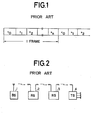
- Fig. 1 is an illustration of the frame organization of prior art time-division multiplexed signals;
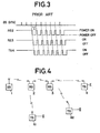
- Fig. 2 is a schematic illustration of a base station, repeater stations and a terminal station connected in tandem;
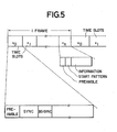
- Fig. 3 is a timing diagram illustrating the detail of the battery saving operation of Fig. 3;
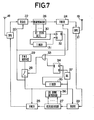
- Fig. 4 is an illustration of a time-division multiple access comunication network in which the present invention is incorporated;
- Fig. 5 is an illustration of a frame organization of the time-division multiplexed signals according to the present invention employed in the system of Fig. 5;
- Fig. 6 is a block diagram of the base station according to the present invention;
- Fig. 7 is a block diagram of a repeater station according to the present invention;
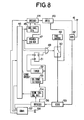
- Fig. 8 is a block diagram of a terminal station according to the present invention;
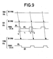
- Fig. 9 is a timing diagram of battery saving operations effected in the base station, a repeater station and a terminal station according to the present invention;
- Fig. 10 is a timing diagram of the operation of the base, repeater and terminal stations when handling a terminating call signal; and
- Fig. 11 is a timing diagram of the operation of the base, repeater and terminal stations when handling an originating call signal.
- Before going into the detail of the present invention, reference is first made to Figs. 1-4 in which a time-division multiplexed (TDM) radiocommunication network is shown operating according to a prior art power saving mode.
- In Fig. 1, channels are allotted to different time slots (No. 0, No. 1 to No. n) within a frame. Sync signal is used to enable a radiocommunication network (Fig. 2) to discriminate between different time slots. Such radiocommunication network includes a base station connected to the public telecommunication network, one or
more repeater stations terminal stations 4 all of which are connected in tandem. To ensure communication during power saving modes in which power supply is interrupted at regular intervals, power saving operation is also synchronized between the stations. If all channels are idle, the base station transmits a battery saving synchronization signal (BS sync signal) at regular intervals, Fig. 3. Battery saving operation is initiated when three of such sync signals, for example, are correctly received in succession by the repeater and terminal stations. - The turn-on period of the power saving operation is determined so that it allows repeater and terminal stations to receive battery saving sync signals during such periods. More specifically, when the repeater and terminal stations have received three BS sync signals consecutively, these stations cut off power supply to their power-consuming principal units for a period tl, Fig. 3, and turn on power supply again to detect a fourth BS sync signal. In response to the detection of the fourth BS sync signal, power supply is again turned off for a predetermined period. The process is repeated until the base station receives a call terminating to it from the public network or a call originating from
terminal station 4. When the base station detects a terminating call, it immediately stops the transmission of BS sync signal to establish a connection to the destination terminal station. When a call is originated fromterminal station 4, it sends an originating call signal to thebase station 1 during the interval between successive BS sync signals. Upon detection of the originating call signal, thebase station 1 immediately halts the transmission of BS sync signals to establish connection. - If the power saving system of this type is to be employed in a time-division multiple access network (TDMA) as shown in Fig. 4 in which the
repeater stations terminal stations 61 and 62, it is impossible to effect the power saving operation forstations 61 and 62 if connection is established betweenbase station 1 andterminal station 4. - Fig. 5 shows a frame organization employed in the TDMA radiocommunication network of Fig. 4. As shown in an expanded form, the time slot No. 0 includes a preamble, a sync signal and a battery saving sync signal. The time slots No. 1 to No. n are data slots each including a preamble, a start pattern which indicates the beginning of an information signal that follows.
- As shown in Fig. 6, the
base station 1 of Fig. 4 comprises aline concentrator 5 connected to aswitching system 12 which forms part of the public telecommunication network. Signals intercepted by an antenna 6 are fed through an antenna duplexer 7 and areceiver 8 to adecoder 9 the output of which is connected to theline concentrator 5. Theline concentrator 5 has its output terminals coupled to anencoder 10 whose output is coupled by way of a transmitter 11 and antenna duplexer 7 to antenna 6. Anoriginating call detector 13 is connected between theline concentrator 5 anddecoder 9 and a terminatingcall signal generator 14 is connected between theline concentrator 5 andencoder 10. The originating call signal detected bydetector 13 contains a code identifying the originating terminal station. The terminating call signal generated bygenerator 14, on the other hand, contains a selective code for selecting a time slot assigned to the destination terminal station. Async generator 16 provides clock pulses to a battery savingsync generator 17 whose output is connected toencoder 10 and terminatingcall signal generator 14. - Fig. 7 is a block diagram of each of
repeater stations Antennas antenna duplexers Antenna duplexer 20 has its output coupled throughreceiver 22 to aregenerator 26 and thence to thetransmitter 24. The output oftransmitter 24 is connected to theantenna duplexer 21 whose output is coupled to areceiver 23 which in turn is connected through aregenerator 27 to atransmitter 25. The output oftransmitter 25 is connected to theantenna duplexer 20. Apower switch 28 is provided having a stationary contact connected to thereceivers transmitters - To
regenerator 27 is connected aBS sync detector 36 whose output is coupled to atiming circuit 35 and to adelay circuit 37. The output oftiming circuit 35 is connected to the set input of a flip-flop 34 and the output ofdelay circuit 35 is connected to the reset input of the flip-flop. The output of flip-flop 34 is connected to one input of anOR gate 33, the output of which is connected to the control terminal of thepower switch 28. To theregenerator 26 is connected astart pattern detector 30 whose output is applied to atiming circuit 31 and to the set input of a flip-flop 32 which is arranged to be reset in response to an output from thetiming circuit 31. The output of flip-flop 32 is connected to the second input ofOR gate 33. - Fig. 8 is a block diagram of each of the terminal stations of Fig. 4.
Antenna 41 is coupled by way of anantenna duplexer 42 to atransmitter 43 and areceiver 55.Power source 48 is connected through the moving contact of aswitch 50 to thereceiver 55 andtransmitter 43. The output of thereceiver 55 is applied to the input of adecoder 56. The output of anencoder 44 is coupled to the input of thetransmitter 43. The output of acovnerter 57 to which a telephone set 58 is connected is connected to alogic circuit 46. The outputs of thelogic circuit 46 anddecoder 56 are applied to theconverter 57. To thedecoder 56 is connected aBS sync detector 53 and a terminatingcall signal detector 54, the output of theBS sync detector 53 being connected to atimer 52 and to the reset input of a flip-flop 51. The output oftimer 52 is connected to the set input of flip-flop 51. The output of flip-flop 51 is connected to one input of anOR gate 49 whose output is connected to the control terminal of aswitch 50. the output of terminatingcall detector 54 is connected tologic circuit 46. To theencoder 44 is connected an originatingcall signal generator 45, ananswer signal generator 47 and aconverter 57. A first output fromlogic circuit 46 is applied to terminatingcall signal generator 45 and toOR gate 49 and a second output fromlogic circuit 46 is applied to answersignal generator 47 andOR gate 49. As in repeater stations,transmitter 43 andreceiver 55 account for a substantial fraction of the total power consumption of the terminal stations. - The operation of the power saving system will be described briefly with reference to Figs. 9 to 11.
-
Repeater stations terminal stations - Upon receipt of a BS sync signal,
stations repeater station 2 is disabling its power saving operation. Upon receipt of the answer signal, therepeater station 2 regenerates it and sends it to thebase station 1 and at the same time disables its power saving operation as indicated at A in Fig. 10 which would otherwise be effected in response to a preceding BS sync signal. As a result, a connection is set up betweenbase station 1 and terminal station 61 to allow the call to proceed regardless of the presence of BS sync signals. The same disabling operation occurs in the terminal station 61 as shown at B. While the disabling operation is in progress in the stations noted above, thebase station 1 is constantly sending BS sync signals so that the other stations can operate on the power saving mode. - When an originating call is received from a terminal station, operation will proceed as indicated in Fig. ll in which C and D represent battery saving disablements corresponding respectively to those marked A and B in Fig. 10. During the time power saving operation is being disabled, terminal station 61 transmits an originating call signal to the associated
repeater station 2 which regenerates and sends it to thebase station 1 while disabling power saving operation. Thereafter, thebase station 1 and the terminal station 61 establish a talking connection regardless of the presence of the BS sync signals. During this time other repeater and terminal stations are constantly performing battery saving operations. - A detailed description on the operation of the base station, repeater and terminal stations will further be given with reference to Figs. 6 to 8.
- In Fig. 6, a BS sync signal is generated in the
base station 1 by BSsync signal generator 17 in response to the output of thesync pulse generator 16. This BS sync signal is passed throughencoder 10, transmitter 11, antenna duplexer 7 to antenna 6 and transmitted to therepeater station 2 and relayed throughrepeater station 3 to terminal stations. When a call is terminated at theline concentrator 5 through a switched connection estalished by switchingsystem 12, the time-division multiplexed signal of the call is passed through an idle link of the concentrator to the terminatingcall signal generator 14. A terminating call signal is generated for each of the successive time slots and transmitted to therepeater station 2 during the interval between successive BS sync signals. - When a call is originated from a terminal station, an originating call signal is transmitted from this terminal station through one or more repeater stations to the base station which receives it through antenna 6, duplexer 7,
receriver 8 anddecoder 9 at originatingcall signal detector 13. Theline concentrator 5 proceeds to connect the time slot of the originating call to theswitching system 12. - In Fig. 7, during idle times each of the repeater stations is constantly receiving BS sync signals transmitted from the base station. The received BS sync signal is conducted through
antenna 19,duplexer 21,receiver 23 andregenerator 27 toBS sync detector 36 which delivers an output signal to delaycircuit 37 and totimer 35. At the same time, theregenerator 27 regenerates a BS sync signal and transmits it throughtransmitter 25,duplexer 20 andantenna 18 to repeater and terminal stations. Thedelay circuit 37 introduces a delay t0 as shown at Fig. 9 to wait for the regenerated BS sync signal to be transmitted. After transmission of the regenerated BS sync signal, thedelay circuit 37 resets the flip-flop 34 which in turn provides a turn-off signal throughOR gate 33 to thepower switch 28, whereby power supply fromsource 29 toreceivers transmitters - Concurrently, the timer is performing a timing action in response to the output of
BS sync detector 36 so that at the end of an interval tl from the onset of the timing action the flip-flop 34 is triggered into a set condition. When this occurs, a turn-on signal is supplied to theswitch 28 to reactivatereceivers transmitters antenna 18 and applied toreceiver 22 and thence to regnerator 26 where the answer signal is regenerated and sent throughtransmitter 24 fromantenna 19 to the base station. The regenerated answer signal is also applied to startpattern detector 30 which identifies it as the onset of a signal that follows and triggers flip-flop 32 into a set condition, causing a turn-on signal to be applied throughOR gate 33 to thepower switch 28.Timer 31 is also triggered by the output of thestart pattern detector 30 to begin a timing action. If the repeater station is receiving speech signals after a connection is established or receiving answer signals in succession from terminal stations during that interval of the timing action, thetimer 31 will be retriggered so that flip-flop 32 remains in the set condition. At the end of a call, thetimer 31 resets the flip-flop 32 to turn offswitch 28 to effect battery saving operation. When an originating call is detected in a terminal station, an orignating call signal is transmitted from it to the repeater station during the interval between successive BS sync signals as shown in Fig. ll. This originating call signal is also intercepted byantenna 18 and detected by thestart pattern detector 30 to disable the power saving operation in a manner similar to that effected upon reception of answer signals. - In Fig. 9, during idle times BS sync signals relayed from a repeater station are received by terminal stations at
antenna 41 and fed throughduplexer 42 andreceiver 55 todecoder 56 and detected byBS sync detector 53. The output ofBS sync detector 53 resets flip-flop 51 to apply a turn-off signal topower switch 50 through ORgate 49, cutting of power supply totransmitter 43 andreceiver 55. The output ofBS sync detector 53 concurrently activatestimer 52 to initiate a timing action. After a predetermined interval, the output oftimer 52 triggers the flip-flop 51 to set condition to provide a turn-on signal to switch 50 to reconnect power toreceiver 43 andtransmitter 55. The terminating call signal relayed from the repeater station is detected by terminatingcall signal detector 54 whose output is translated bylogic circuit 46.Logic circuit 46 applies an output signal toconverter 57 which rings the telephone set 58, while at the same time it applies a turn-on signal throughOR gate 49 to switch 50 and activatesanswer signal generator 47. Thus,receiver 55 andtransmitter 43 remain activated until the talking connection is disconnected. The output of theanswer signal generator 47 is encoded byencoder 44 and fed throughtransmitter 43 toantenna 41 and transmitted to a repeater station. - A call is originated from any of the terminal stations by hooking off the telephone set 58. The off-hook condition is detected by
converter 57 which signals thelogic cirucit 46 to activate the originatingcall signal generator 45 and apply a turn-on signal to switch 50.Transmitter 43 andreceiver 55 are activated until the end of the originating call. The originating call signal is supplied throughencoder 44 andtransmitter 43 toantenna 41 and transmitted to repeater stations. - The foregoing description shows only a preferred embodiment of the present invention. Various modifications are apparent to those skilled in the art without departing from the scope of the present invention which is only limited by the appended claims. Therefore, the embodiment shown and described is only illustrative, not restrictive.
Claims (12)
Applications Claiming Priority (2)
| Application Number | Priority Date | Filing Date | Title |
|---|---|---|---|
| JP135389/83 | 1983-07-25 | ||
| JP58135389A JPS6027241A (en) | 1983-07-25 | 1983-07-25 | Battery saving system of radio relay system |
Publications (3)
| Publication Number | Publication Date |
|---|---|
| EP0132406A2 true EP0132406A2 (en) | 1985-01-30 |
| EP0132406A3 EP0132406A3 (en) | 1987-09-16 |
| EP0132406B1 EP0132406B1 (en) | 1990-07-18 |
Family
ID=15150560
Family Applications (1)
| Application Number | Title | Priority Date | Filing Date |
|---|---|---|---|
| EP84305038A Expired - Lifetime EP0132406B1 (en) | 1983-07-25 | 1984-07-24 | Power saving system for time-division multiple access radiocommunication network |
Country Status (5)
| Country | Link |
|---|---|
| US (1) | US4577315A (en) |
| EP (1) | EP0132406B1 (en) |
| JP (1) | JPS6027241A (en) |
| AU (1) | AU559384B2 (en) |
| CA (1) | CA1220290A (en) |
Cited By (7)
| Publication number | Priority date | Publication date | Assignee | Title |
|---|---|---|---|---|
| EP0200275A1 (en) * | 1985-05-03 | 1986-11-05 | Telecommunications Radioelectriques Et Telephoniques T.R.T. | Multiplex information transmission system |
| EP0238880A2 (en) * | 1986-02-27 | 1987-09-30 | Nec Corporation | Mobile station and a mobile radio communication network in which electric power is saved without reduction of an activity ratio of radio communication channels |
| EP0245024A2 (en) * | 1986-05-06 | 1987-11-11 | Nec Corporation | Radio communication system with power saving disablement prior to call handling processes |
| EP0375067A1 (en) * | 1988-12-23 | 1990-06-27 | Philips Electronics Uk Limited | Power economising in multiple user radio systems |
| EP0412583A2 (en) * | 1986-03-25 | 1991-02-13 | Motorola, Inc. | Method and apparatus for controlling a TDM communication device |
| EP0663733A1 (en) * | 1994-01-13 | 1995-07-19 | Walter Koch | Remote control for an electrically operated remote controlled apparatus |
| US8406161B2 (en) | 2006-08-18 | 2013-03-26 | Fujitsu Limited | Timing adjustment in multi-hop communication system |
Families Citing this family (60)
| Publication number | Priority date | Publication date | Assignee | Title |
|---|---|---|---|---|
| US4675863A (en) | 1985-03-20 | 1987-06-23 | International Mobile Machines Corp. | Subscriber RF telephone system for providing multiple speech and/or data signals simultaneously over either a single or a plurality of RF channels |
| JPH06101698B2 (en) * | 1986-04-25 | 1994-12-12 | 日本電気株式会社 | Wireless telephone |
| US4804954A (en) * | 1987-04-30 | 1989-02-14 | Motorola, Inc. | Battery saving method for portable communications receivers |
| IL85558A (en) * | 1987-04-30 | 1992-01-15 | Motorola Inc | Personal message receiving device with separate information presentation means |
| US4839645A (en) * | 1987-08-06 | 1989-06-13 | Lill Thomas M | Weather data transmitting system |
| US7106819B1 (en) * | 1987-11-20 | 2006-09-12 | Interdigital Technology Corporation | Plural subscriber system utilizing synchronized timeslots on a single frequency |
| US4860005A (en) * | 1988-01-07 | 1989-08-22 | Motorola, Inc. | Communication receiver with automatic turn on/off |
| US5150361A (en) * | 1989-01-23 | 1992-09-22 | Motorola, Inc. | Energy saving protocol for a TDM radio |
| US5128938A (en) * | 1989-03-03 | 1992-07-07 | Motorola, Inc. | Energy saving protocol for a communication system |
| US5459729C1 (en) * | 1989-07-25 | 2002-03-19 | Raychem Corp | Digital added main line system |
| SE464437B (en) * | 1989-08-25 | 1991-04-22 | Ericsson Telefon Ab L M | METHOD OF A MOGIL RADIO RECEIVER TO REDUCE THE POWER RECEIVER'S REQUIREMENT |
| US4964121A (en) * | 1989-08-30 | 1990-10-16 | Motorola, Inc. | Battery saver for a TDM system |
| JP2944113B2 (en) * | 1989-11-01 | 1999-08-30 | 日本電気株式会社 | Battery saving system |
| US5584048A (en) * | 1990-08-17 | 1996-12-10 | Motorola, Inc. | Beacon based packet radio standby energy saver |
| JPH04103228A (en) * | 1990-08-22 | 1992-04-06 | Mitsubishi Electric Corp | Radio repeater and radio equipment |
| US5224152A (en) * | 1990-08-27 | 1993-06-29 | Audiovox Corporation | Power saving arrangement and method in portable cellular telephone system |
| US5646606A (en) * | 1991-05-30 | 1997-07-08 | Wilson; Alan L. | Transmission of transmitter parameters in a digital communication system |
| US5440560A (en) * | 1991-12-24 | 1995-08-08 | Rypinski; Chandos A. | Sleep mode and contention resolution within a common channel medium access method |
| US5446453A (en) * | 1992-04-09 | 1995-08-29 | Matsushita Electric Industrial Co., Ltd. | Residential facility control system |
| NZ255617A (en) * | 1992-09-04 | 1996-11-26 | Ericsson Telefon Ab L M | Tdma digital radio: measuring path loss and setting transmission power accordingly |
| US5406559A (en) * | 1992-11-02 | 1995-04-11 | National Semiconductor Corporation | Isochronous link protocol |
| EP0596651A1 (en) | 1992-11-02 | 1994-05-11 | National Semiconductor Corporation | Network for data communication with isochronous capability |
| USRE39395E1 (en) | 1992-11-02 | 2006-11-14 | Negotiated Data Solutions Llc | Data communication network with transfer port, cascade port and/or frame synchronizing signal |
| EP0596648A1 (en) | 1992-11-02 | 1994-05-11 | National Semiconductor Corporation | Network link endpoint capability detection |
| USRE39116E1 (en) | 1992-11-02 | 2006-06-06 | Negotiated Data Solutions Llc | Network link detection and generation |
| SE516173C2 (en) * | 1993-02-16 | 2001-11-26 | Ericsson Telefon Ab L M | Device for telecommunications |
| CA2127673C (en) * | 1993-07-16 | 2000-02-15 | Akira Suzuki | Radio communication system |
| US5546383A (en) | 1993-09-30 | 1996-08-13 | Cooley; David M. | Modularly clustered radiotelephone system |
| US6331971B1 (en) * | 1993-11-01 | 2001-12-18 | Telefonaktiebolaget Lm Ericsson (Publ) | Enhanced sleep mode in radiocommunication systems |
| FI94685C (en) * | 1993-11-22 | 1995-10-10 | Nokia Mobile Phones Ltd | Key switched power source for time-multiplexed radio telephone systems |
| AU1934595A (en) * | 1994-03-04 | 1995-09-18 | Motorola, Inc. | Remote meter reading power reduction method |
| US5590396A (en) * | 1994-04-20 | 1996-12-31 | Ericsson Inc. | Method and apparatus for a deep-sleep mode in a digital cellular communication system |
| US6243399B1 (en) | 1994-07-21 | 2001-06-05 | Interdigital Technology Corporation | Ring signal generator |
| DK0775388T3 (en) | 1994-07-21 | 2003-01-27 | Interdigital Tech Corp | Method and device for controlling power consumption for a subscriber unit in a communication system |
| US6775531B1 (en) | 1994-07-21 | 2004-08-10 | Interdigital Technology Corporation | Subscriber terminal temperature regulation |
| US5463261A (en) * | 1994-10-19 | 1995-10-31 | Minnesota Mining And Manufacturing Company | Power conservation device for a peripheral interface module |
| US5745860A (en) * | 1994-12-16 | 1998-04-28 | Telefonaktiebolaget Lm Ericsson | Method and system of data transmission and reception in a mobile station within a radio telecommunications system |
| US5533018A (en) | 1994-12-21 | 1996-07-02 | National Semiconductor Corporation | Multi-protocol packet framing over an isochronous network |
| US5668814A (en) * | 1995-03-20 | 1997-09-16 | Raychem Corporation | Dual DDS data multiplexer |
| AU5848896A (en) * | 1995-05-23 | 1996-12-11 | Telefonaktiebolaget Lm Ericsson (Publ) | Method and apparatus for supporting delivery of short messag e service messages to sleeping mobile stations in a cellular communications system |
| CN1102325C (en) * | 1995-12-04 | 2003-02-26 | 摩托罗拉公司 | Method for dynamically changing selection of control frame of call receiving equipment in mixed system environment |
| US7590083B2 (en) | 1995-12-07 | 2009-09-15 | Transcore Link Logistics Corp. | Wireless packet data distributed communications system |
| US5838720A (en) * | 1996-02-23 | 1998-11-17 | Teletransactions, Inc. | Transceiver control with sleep mode operation |
| US6236674B1 (en) | 1996-02-23 | 2001-05-22 | Teletransactions, Inc. | Transceiver control with sleep mode operation |
| US5805597A (en) * | 1996-06-04 | 1998-09-08 | National Semiconductor Corporation | Method and apparatus for providing low power basic telephony type service over a twisted pair ethernet physical layer |
| JP2852245B2 (en) * | 1996-06-18 | 1999-01-27 | 静岡日本電気株式会社 | Radio selective call receiver |
| US5995492A (en) * | 1996-06-28 | 1999-11-30 | Ctp Systems, Ltd. | Method and apparatus for using duality to remotely communicate |
| DE19642265C1 (en) * | 1996-10-11 | 1998-01-29 | Becker Gmbh | Low-current operation mode access method for ring network |
| US6081733A (en) * | 1997-04-16 | 2000-06-27 | Motorola, Inc. | Communication control apparatus and method |
| US6028849A (en) * | 1997-04-18 | 2000-02-22 | Vlsi Technology, Inc. | Communication timing control arrangement and method thereof |
| JP3119605B2 (en) * | 1997-10-28 | 2000-12-25 | 埼玉日本電気株式会社 | Wireless base station |
| US6282204B1 (en) | 1997-12-19 | 2001-08-28 | Terayon Communication Systems, Inc. | ISDN plus voice multiplexer system |
| JP4622028B2 (en) * | 2000-03-17 | 2011-02-02 | ソニー株式会社 | Content processing apparatus and content processing system |
| WO2009044368A2 (en) * | 2007-10-03 | 2009-04-09 | Nxp B.V. | Power saving method and system for wireless communications device |
| KR20110139744A (en) * | 2009-03-18 | 2011-12-29 | 코닌클리즈케 필립스 일렉트로닉스 엔.브이. | System for controlling a device |
| KR101589434B1 (en) * | 2009-06-12 | 2016-01-29 | 삼성전자주식회사 | Apparatus and method for connecting wlan in portable terminal |
| US8599768B2 (en) * | 2009-08-24 | 2013-12-03 | Intel Corporation | Distributing group size indications to mobile stations |
| KR20140051520A (en) * | 2012-10-23 | 2014-05-02 | 삼성전자주식회사 | Method and apparatus for reducing power consumption of a base station in a radio communication system |
| US10462738B1 (en) | 2018-07-24 | 2019-10-29 | Motorola Solutions, Inc. | Base station device with reduced power consumption and method thereof |
| US11224095B2 (en) | 2020-03-06 | 2022-01-11 | Motorola Solutions, Inc. | Adaptive operation of a control channel of a radio frequency site controller |
Citations (3)
| Publication number | Priority date | Publication date | Assignee | Title |
|---|---|---|---|---|
| GB2072908A (en) * | 1980-03-28 | 1981-10-07 | Nippon Electric Co | Digital radio paging communication system |
| JPS56165425A (en) * | 1980-05-16 | 1981-12-19 | Meisei Electric Co Ltd | Power supplying system of electric machinery |
| EP0085575A2 (en) * | 1982-02-01 | 1983-08-10 | Nec Corporation | Power supply systems for use in radio communication systems |
Family Cites Families (5)
| Publication number | Priority date | Publication date | Assignee | Title |
|---|---|---|---|---|
| GB1554411A (en) * | 1975-08-09 | 1979-10-17 | Communications Patents Ltd | Control systems |
| US4245347A (en) * | 1978-01-18 | 1981-01-13 | Hutton Thomas J | Remote equipment control system with low duty cycle communications link |
| US4369443A (en) * | 1979-12-26 | 1983-01-18 | Meta Systems, Inc. | Message communication system with message storage |
| US4424514A (en) * | 1981-10-13 | 1984-01-03 | Motorola Inc | Decoder for transmitted message activation code |
| JPS58207733A (en) * | 1982-05-28 | 1983-12-03 | Nec Corp | Battery saving circuit |
-
1983
- 1983-07-25 JP JP58135389A patent/JPS6027241A/en active Granted
-
1984
- 1984-07-24 AU AU30994/84A patent/AU559384B2/en not_active Expired
- 1984-07-24 EP EP84305038A patent/EP0132406B1/en not_active Expired - Lifetime
- 1984-07-24 CA CA000459511A patent/CA1220290A/en not_active Expired
- 1984-07-24 US US06/633,993 patent/US4577315A/en not_active Expired - Lifetime
Patent Citations (3)
| Publication number | Priority date | Publication date | Assignee | Title |
|---|---|---|---|---|
| GB2072908A (en) * | 1980-03-28 | 1981-10-07 | Nippon Electric Co | Digital radio paging communication system |
| JPS56165425A (en) * | 1980-05-16 | 1981-12-19 | Meisei Electric Co Ltd | Power supplying system of electric machinery |
| EP0085575A2 (en) * | 1982-02-01 | 1983-08-10 | Nec Corporation | Power supply systems for use in radio communication systems |
Non-Patent Citations (2)
| Title |
|---|
| INTERNATIONAL CONFERENCE ON COMMUNICATIONS, Toronto, 4th-7th June 1978, vol. 3, pages 41.5.1-41.5.5, IEEE, New York, US; F. BARRESI et al.: "The problem of radio telephone systems for rural subscribers system RTR 102" * |
| PATENT ABSTRACTS OF JAPAN, vol. 6, no. 52 (E-100)[930], 7th April 1982; & JP-A-56 165 425 (MEISEI DENKI K.K.) 19-12-1981 * |
Cited By (12)
| Publication number | Priority date | Publication date | Assignee | Title |
|---|---|---|---|---|
| EP0200275A1 (en) * | 1985-05-03 | 1986-11-05 | Telecommunications Radioelectriques Et Telephoniques T.R.T. | Multiplex information transmission system |
| FR2581493A1 (en) * | 1985-05-03 | 1986-11-07 | Trt Telecom Radio Electr | MULTIPLEX INFORMATION TRANSMISSION SYSTEM |
| EP0238880A2 (en) * | 1986-02-27 | 1987-09-30 | Nec Corporation | Mobile station and a mobile radio communication network in which electric power is saved without reduction of an activity ratio of radio communication channels |
| EP0238880A3 (en) * | 1986-02-27 | 1989-04-12 | Nec Corporation | Mobile station and a mobile radio communication network in which electric power is saved without reduction of an activity ratio of radio communication channels |
| EP0412583A2 (en) * | 1986-03-25 | 1991-02-13 | Motorola, Inc. | Method and apparatus for controlling a TDM communication device |
| EP0412583A3 (en) * | 1986-03-25 | 1991-05-29 | Motorola, Inc. | Method and apparatus for controlling a tdm communication device |
| EP0245024A2 (en) * | 1986-05-06 | 1987-11-11 | Nec Corporation | Radio communication system with power saving disablement prior to call handling processes |
| EP0245024A3 (en) * | 1986-05-06 | 1989-08-09 | Nec Corporation | Radio communication system with power saving disablement prior to call handling processes |
| EP0375067A1 (en) * | 1988-12-23 | 1990-06-27 | Philips Electronics Uk Limited | Power economising in multiple user radio systems |
| EP0663733A1 (en) * | 1994-01-13 | 1995-07-19 | Walter Koch | Remote control for an electrically operated remote controlled apparatus |
| US8406161B2 (en) | 2006-08-18 | 2013-03-26 | Fujitsu Limited | Timing adjustment in multi-hop communication system |
| US8923175B2 (en) | 2006-08-18 | 2014-12-30 | Fujitsu Limited | Timing adjustment in multi-hop communication system |
Also Published As
| Publication number | Publication date |
|---|---|
| AU3099484A (en) | 1985-01-31 |
| AU559384B2 (en) | 1987-03-05 |
| CA1220290A (en) | 1987-04-07 |
| EP0132406A3 (en) | 1987-09-16 |
| US4577315A (en) | 1986-03-18 |
| EP0132406B1 (en) | 1990-07-18 |
| JPS6321368B2 (en) | 1988-05-06 |
| JPS6027241A (en) | 1985-02-12 |
Similar Documents
| Publication | Publication Date | Title |
|---|---|---|
| US4577315A (en) | Power saving system for time-division multiple access radiocommunication network | |
| CA1257653A (en) | Radio communication system with power saving disablement prior to call handling processes | |
| EP0085575B1 (en) | Power supply systems for use in radio communication systems | |
| US4553262A (en) | Communications system enabling radio link access for non-trunked radio units to a multifrequency trunked two-way communications systems | |
| EP0214809B1 (en) | Radio telephone system control apparatus and method | |
| EP0631417B1 (en) | Radio telephone system control apparatus and method | |
| JP4472862B2 (en) | Wireless communication method | |
| US4809315A (en) | Cordless telephone system | |
| JPH05500293A (en) | Battery saver for TDM systems | |
| JP2944113B2 (en) | Battery saving system | |
| JPS6277728A (en) | Incoming call signal transmission system for radiotelephony equipment | |
| JP2655412B2 (en) | A call monitoring method for inter-substation mutual calls in a time division multiplexed wireless communication system | |
| CN110012544B (en) | Communication method in time division multiple access mode | |
| JPS58191542A (en) | Mobile communication controlling system | |
| JPH0767169A (en) | Radio communication device | |
| JP3254874B2 (en) | Digital cordless telephone equipment | |
| JP2658879B2 (en) | MONITORING METHOD, MONITORING METHOD, AND TERMINAL OF MULTI-DIRECTIONAL MULTIPLE COMMUNICATION SYSTEM | |
| JP2001016627A (en) | Mobile communication system, base station and mobile station | |
| JPS61172442A (en) | Radio relay system | |
| JP3018376B2 (en) | Wireless relay system | |
| JPS61281629A (en) | Radio communication equipment | |
| JP3084113B2 (en) | No call pattern control method | |
| JPH0533853B2 (en) | ||
| JPH0459818B2 (en) | ||
| JPH0832511A (en) | Simultaneous notice system |
Legal Events
| Date | Code | Title | Description |
|---|---|---|---|
| PUAI | Public reference made under article 153(3) epc to a published international application that has entered the european phase |
Free format text: ORIGINAL CODE: 0009012 |
|
| 17P | Request for examination filed |
Effective date: 19840813 |
|
| AK | Designated contracting states |
Designated state(s): FR GB NL |
|
| PUAL | Search report despatched |
Free format text: ORIGINAL CODE: 0009013 |
|
| AK | Designated contracting states |
Kind code of ref document: A3 Designated state(s): FR GB NL |
|
| 17Q | First examination report despatched |
Effective date: 19890301 |
|
| GRAA | (expected) grant |
Free format text: ORIGINAL CODE: 0009210 |
|
| AK | Designated contracting states |
Kind code of ref document: B1 Designated state(s): FR GB NL |
|
| ET | Fr: translation filed | ||
| PLBE | No opposition filed within time limit |
Free format text: ORIGINAL CODE: 0009261 |
|
| STAA | Information on the status of an ep patent application or granted ep patent |
Free format text: STATUS: NO OPPOSITION FILED WITHIN TIME LIMIT |
|
| 26N | No opposition filed | ||
| PGFP | Annual fee paid to national office [announced via postgrant information from national office to epo] |
Ref country code: NL Payment date: 19970731 Year of fee payment: 14 |
|
| PG25 | Lapsed in a contracting state [announced via postgrant information from national office to epo] |
Ref country code: NL Free format text: LAPSE BECAUSE OF NON-PAYMENT OF DUE FEES Effective date: 19990201 |
|
| NLV4 | Nl: lapsed or anulled due to non-payment of the annual fee |
Effective date: 19990201 |
|
| REG | Reference to a national code |
Ref country code: GB Ref legal event code: IF02 |
|
| PGFP | Annual fee paid to national office [announced via postgrant information from national office to epo] |
Ref country code: FR Payment date: 20030711 Year of fee payment: 20 |
|
| PGFP | Annual fee paid to national office [announced via postgrant information from national office to epo] |
Ref country code: GB Payment date: 20030723 Year of fee payment: 20 |
|
| PG25 | Lapsed in a contracting state [announced via postgrant information from national office to epo] |
Ref country code: GB Free format text: LAPSE BECAUSE OF EXPIRATION OF PROTECTION Effective date: 20040723 |
|
| REG | Reference to a national code |
Ref country code: GB Ref legal event code: PE20 |