EP0133264A1 - Dosing apparatus - Google Patents
Dosing apparatus Download PDFInfo
- Publication number
- EP0133264A1 EP0133264A1 EP84108675A EP84108675A EP0133264A1 EP 0133264 A1 EP0133264 A1 EP 0133264A1 EP 84108675 A EP84108675 A EP 84108675A EP 84108675 A EP84108675 A EP 84108675A EP 0133264 A1 EP0133264 A1 EP 0133264A1
- Authority
- EP
- European Patent Office
- Prior art keywords
- wall
- dosing
- approximately
- central axis
- metering device
- Prior art date
- Legal status (The legal status is an assumption and is not a legal conclusion. Google has not performed a legal analysis and makes no representation as to the accuracy of the status listed.)
- Granted
Links
Images


Classifications
-
- B—PERFORMING OPERATIONS; TRANSPORTING
- B65—CONVEYING; PACKING; STORING; HANDLING THIN OR FILAMENTARY MATERIAL
- B65D—CONTAINERS FOR STORAGE OR TRANSPORT OF ARTICLES OR MATERIALS, e.g. BAGS, BARRELS, BOTTLES, BOXES, CANS, CARTONS, CRATES, DRUMS, JARS, TANKS, HOPPERS, FORWARDING CONTAINERS; ACCESSORIES, CLOSURES, OR FITTINGS THEREFOR; PACKAGING ELEMENTS; PACKAGES
- B65D83/00—Containers or packages with special means for dispensing contents
- B65D83/06—Containers or packages with special means for dispensing contents for dispensing powdered or granular material
Abstract
Ein als Kippdosierer geeignetes Dosiergerät besitzt einen beim Umwenden in eine Tieflage gelangenden, zwischen den freien Enden einer schräg in bezug auf die Gerätemittelachse (A) stehenden Gleitwand (20) und einer Prallwand (12, 13) definierten Austrittskanal (14). Ein solches Dosiergerät läßt ein Dosieren bei einmaligem Kippen und kompaktem Aufbau zu, wenn die Gleitwand (20) durch einen etwa V-förmigen Steg (11) ersetzt wird, die Prallwand aus einer senkrecht zu der Mittelachse (A) stehenden Deckelwand (12) und einer schräg zu der Achse verlaufenden Stirnwand (13) gebildet wird und der Austrittskanal (14, 16) etwa rechtwinklig in bezug auf die Mittelachse (A) nach außen ausläuft.A metering device suitable as a tilting metering device has an outlet channel (14) which, when turned over into a low position, is defined between the free ends of a sliding wall (20) which is inclined with respect to the device center axis (A) and an impact wall (12, 13). Such a dosing device allows dosing with a single tilting and compact construction, if the sliding wall (20) is replaced by an approximately V-shaped web (11), the baffle wall from a cover wall (12) perpendicular to the central axis (A) and an end wall (13) extending obliquely to the axis is formed and the outlet channel (14, 16) runs outward at approximately a right angle with respect to the central axis (A).
Description
Die Erfindung betrifft ein Dosiergerät zum dosierten Ausgeben eines rieselfähigen Produkts aus einem Vorratsbehälter durch eine beim Umwenden in eine Tieflage gelangende, zwischen dem freien Ende einer schräg in Bezug auf die Behälterlängsmittelachse stehenden Gleitwand und einer Prallwand definierte Mündung mit daran anschließendem Austrittskanal des Dosierteils.The invention relates to a metering device for the metered dispensing of a free-flowing product from a storage container by means of a mouth which, when turned over into a low position, is defined between the free end of a sliding wall which is inclined with respect to the longitudinal axis of the container and a baffle with an adjoining outlet channel of the metering part.
Ein Kippdosierer dieser Art zum Ausgeben von Medien aus einem Vorratsbehälter wird in der DE-OS 31 20 234 beschrieben. Die dosierte Ausgabe erfolgt beim zweiten Umwenden des Gerätes durch einen bei dem Umwenden in die Tieflage tretenden Auslaß. Auf dem Weg zwischen Geräteinnenraum und Auslaß befinden sich eine schrägstehende Gleitwand und eine Prallwand. Das freie Ende der Gleitwand reicht bis zu einem vorgegebenen Abstand an die Prallwand heran. Der Auslaß liegt parallel zu der Behälterlängsmittelachse. Die Prallwand besitzt einen Fortsatz, der parallel zum Auslaß hinter die Gleitwand zurückgeführt ist.A tilting meter of this type for dispensing media from a storage container is described in DE-OS 31 20 234. The metered output takes place the second time the device is turned through an outlet that turns low when it is turned. There is an inclined sliding wall and a baffle on the way between the interior of the device and the outlet. The free end of the sliding wall extends up to a predetermined distance from the baffle. The outlet is parallel to the longitudinal axis of the container. The baffle has an extension which is guided parallel to the outlet behind the sliding wall.
Mit dem bekannten Gerät können zwar feine Granulate dosiert werden, das Dosieren erfordert aber ein zweimaliges Kippen bzw. Aufdenkopfstellen der Packung. Dadurch wird das Dosieren nicht nur umständlich, sondern es wird auch ein im Verhältnis zum Dosiervolumen überproportional großes Gerätevolumen erforderlich, da innerhalb des Dosiergeräts mindestens zwei Kammern mit dem vollen Dosiervolumen erforderlich sind. Das erhebliche Gerätevolumen kann entweder innerhalb des Vorratsbehälters angeordnet oder als Aufsatz konzipiert werden. Im ersteren Fall geht sehr viel Füllvolumen verloren, im anderen Fall wird die für den Versand erforderliche Umverpackung aufwendig.Fine granules can be dosed with the known device, but dosing requires the package to be tilted or turned upside down twice. This not only makes dosing cumbersome, it also requires a device volume that is disproportionately large in relation to the dosing volume, since at least two chambers with the full dosing volume are required within the dosing device. The considerable volume of devices can either be internal arranged half of the storage container or designed as an attachment. In the former case, a lot of filling volume is lost, in the other case, the outer packaging required for shipping becomes expensive.
Aus den vorstehenden Gründen werden die bekannten Kippdosierer fast ausschließlich im Kleinmengen-Dosierbereich, etwa bei Zuckerstreuern, eingesetzt. Für erheblich grössere Dosiermengen, wie sie bei Waschpulvern votkommen, mußte das Kippdosierprinzip bisher als systemwidrig angesehen werden, weil es entweder einen unförmig großen und damit nicht wirtschaftlich herzustellenden Dosierkopf oder ein oftmaliges und damit für den Anwender nicht zumutbares Wiederholen des Dosiervorgangs notwendig machte.For the above reasons, the known tilting dosing devices are used almost exclusively in the small quantity dosing range, for example in sugar spreaders. For considerably larger dosages as vot in washing powders ommen k, the Kippdosierprinzip previously had to be regarded as contrary to the system, because it was either a misshapen large and thus not economically produced dosing or that frequent and therefore not zumutbares for the user repeating the dosing necessary.
Der Erfindung liegt die Aufgabe zugrunde, einen kompakten Kippdosierer zu schaffen, mit dem schon beim ersten Dosiervorgang die jeweils gewünschte bzw. vorgegebene Gesamtproduktmenge auszubringen ist. Der Dosierer soll auch so konzipiert werden, daß das pulverförmige bzw. rieselfähige Produkt ohne die Gefahr des Verschüttens gezielt, z.B. in eine Waschmittelkammer einer Waschmaschine, auszugeben ist. Die erfindungsgemäße Lösung ist für das Dosiergerät eingangs genannter Art mit vor der Einlaßmündung angeordneter Prallwand und schrägstehender Gleitwand gekennzeichnet durch eine zusammen mit der Gleitwand einen etwa V-förmigen Steg bildende Ansatzwand am freien Ende der Gleitwand; eine aus einer etwa senkrecht zu der Behälterlängsmittelachse stehenden Deckelwand und einer mit einer Schräge etwa parallel zu der Gleitwand verlaufenden Stirnwand bestehende Prallwand, und einen zwischen einer etwa senkrecht zu der Behälterlängsmittelachse stehenden Gerätebodenplatte und der Stirnwand etwa rechtwinklig in Bezug auf die Mittelachse nach außen mündenden Austrittskanal.The object of the invention is to create a compact tilting metering device with which the desired or predetermined total product quantity can be applied in the first metering process. The dosing device should also be designed so that the powdery or free-flowing product is targeted without the risk of spilling, e.g. into a detergent dispenser in a washing machine. The solution according to the invention is characterized for the dosing device of the type mentioned above with a baffle arranged in front of the inlet mouth and an inclined sliding wall by an extension wall forming an approximately V-shaped web together with the sliding wall at the free end of the sliding wall; an outlet wall which is approximately perpendicular to the longitudinal axis of the container and an end wall which runs with a slope approximately parallel to the sliding wall, and an outlet channel which opens out approximately at a right angle with respect to the central axis between an appliance base plate approximately perpendicular to the longitudinal axis of the container and the end wall .
Ein wesentliches Merkmal des erfindungsgemäßen Geräts ist die Anordnung des Austrittskanals etwa rechtwinklig zu der Mittelachse des Vorratsbehälters. Daher wird es - anders als bei den bekannten Kippdosierern vorliegender Art, deren Ausgielimündung etwa parallel zur Behälterachse verläuft - bei dem erfindungsgemäßen Aufbau ermöglicht, nach dem Vordosieren von Produkt durch einfaches Rückschwenken des Vorratsbehälters um etwa 90° die vordosierte Produktmenge gezielt auszubringen. Mit anderen Worten heißt das, daß die beim Schwenken in die Überkopfstellung vordosierte Produktmenge bereits während der ersten Hälfte des Zurückschwenkens aus dem Austrittskanal ausgelassen werden kann.An essential feature of the device according to the invention is the arrangement of the outlet channel approximately at right angles to the central axis of the storage container. Therefore - in contrast to the known tilting dosing devices of the present type, the pouring mouth of which runs approximately parallel to the container axis - it is made possible in the construction according to the invention, after the pre-dosing of product, by simply swiveling back the storage container by approximately 90 ° to apply the pre-dosed amount of product in a targeted manner. In other words, this means that the amount of product pre-metered when swiveling into the overhead position can be discharged from the outlet channel during the first half of the swiveling back.
Die Funktion wird noch verbessert, wenn die schräge Stirnwand ausgehend von der Deckelwand so weit reicht, daß sie die gedachte Radialebene durch das freie Ende der Ansatzwand materiell durchstößt. Bei solcher gegenseitiger Zuordnung von V-förmigem Steg und Stirnwand können rieselfähige Produkte in der Überkopfstellung des Geräts besonders exakt vordosiert werden. Die Gefahr eines Überlaufs des Dosierraums besteht nicht.The function is further improved if the sloping front wall extends from the cover wall to such an extent that it penetrates the imaginary radial plane through the free end of the extension wall. With such a mutual assignment of the V-shaped web and the bulkhead, free-flowing products can be predosed particularly precisely in the overhead position of the device. There is no risk of the metering chamber overflowing.
Der Austrittskanal selbst ist letzten Endes eine weitgehend gerade Fortsetzung des zwischen dem freien Ende des V-förmigen Stegs und der Stirnwand gebildeten Spalts, der Kanal hat daher zumindest an seiner Einlaufseite einen flachen etwa rechteckigen Querschnitt. Um ein gezieltes Ausbringen des Produkts zu ermöglichen, ist es vorteilhaft, den Austrittskanal in Richtung auf seinen Ausgang von den Seiten her zu verengen. Vorteilhaft ist in diesem Zusammenhang ein Auslaufen in einen zylindrischen, zum Aufsetzen einer Verschlußkappe ausgebildeten Austrittsstutzen.The outlet channel itself is ultimately a largely straight continuation of the gap formed between the free end of the V-shaped web and the end wall, the channel therefore has a flat, approximately rectangular cross section, at least on its inlet side. In order to enable the product to be discharged in a targeted manner, it is advantageous to narrow the outlet channel from the sides in the direction of its outlet. In this context, it is advantageous to run out into a cylindrical outlet connector designed to fit a closure cap.
Das erfindungsgemäße Dosiergerät besitzt vorteilhaft auch ein Kupplungsstück zum Aufsetzen auf die Austrittsöffnung des jeweils zu bestückenden Vorratsbehälters. Das Kupplungsstück kann den Erfordernissen der Mündung des Vorratsbehälters entsprechend ausgebildet werden. In den Bereich zwischen Dosiergerät und Kupplungsstück kann auch eine Verschließmöglichkeit integriert werden, wenn das eigentliche Dosiergerät relativ zum Kupplungsstück um die Behälterlängsmittelachse drehbar gelagert wird und durch die Relativdrehung zur Deckung zu bringende Durchlässe in der Decke des Kupplungsteils und im Boden des Geräteteils vorgesehen werden.The dosing device according to the invention advantageously also has a coupling piece for placement on the outlet opening of the storage container to be loaded in each case. The coupling piece can be designed according to the requirements of the mouth of the storage container. A locking option can also be integrated in the area between the metering device and the coupling piece if the actual metering device is rotatably mounted relative to the coupling piece about the longitudinal axis of the container and passages to be brought to cover by the relative rotation are provided in the ceiling of the coupling part and in the bottom of the device part.
Ein weiterer Vorteil des erfindungsgemäßen Kippdosierers besteht darin, daß der V-förmige Steg etwa radial in Bezug auf die Behälter- bzw. Gerätelängsmittelachse bzw. etwa parallel zu dem Geräteboden in Richtung auf den Austrittskanal verschiebbar gelagert sein kann. Das ist im Prinzip möglich, weil der vorliegende Kippdosierer nur einen einzigen Dosierraum und nicht - wie in bekannten Fällen - zwei etwa gleich große Dosierräume benötigt. Es wird also ein Kippdosierer geschaffen, dessen Dosiervolumen in weiten Bereichen den jeweiligen Erfordernissen, z.B. dem Härtegrad des zur Verfügung stehenden Wassers bei Waschpulver, anzupassen ist.Another advantage of the tilting dosing device according to the invention is that the V-shaped web can be mounted so as to be displaceable approximately radially with respect to the container or device longitudinal center axis or approximately parallel to the device bottom in the direction of the outlet channel. In principle, this is possible because the tilting dosing device at hand only requires a single dosing room and not - as in known cases - two dosing rooms of approximately the same size. A tipping dosing device is thus created, the dosing volume of which varies widely over the respective requirements, e.g. the degree of hardness of the water available for washing powder.
Anhand der schematischen Darstellung von Ausführungsbeispielen werden weitere Einzelheiten der Erfindung erläutert. Es zeigen:
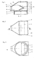
- Fig. 1 einen Schnitt parallel zur Behälterlängsmittelachse eines Dosiergeräts;
- Fig. 2 die Draufsicht in Richtung der Mittelachse auf das Dosiergerät nach Fig. 1;
- Fig. 3 die Ansicht von unten in Richtung der Mittelachse auf das Dosiergerät nach Fig. 1;
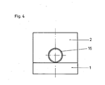
- Fig. 4 eine Ansicht in Richtung auf den Austrittsstutzen des Dosiergeräts nach Fig. 1;
- Fig. 5 die Überkopfstellung des Dosiergeräts nach Fig. 1;
- Fig. 6 die Dosierstellung des Dosiergeräts nach Fig. 1;
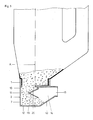
- Fig. 7 eine Seitenansicht, teilweise im Schnitt, senkrecht zu der Mittelachse eines Dosiergeräts mit verstellbarem Dosiervolumen; und
- Fig. 8 ein Dosiergerät nach Fig. 7 in der Ansicht gegen die dem Austrittsstutzen gegenüberliegende Hinterwand.
- 1 shows a section parallel to the longitudinal axis of the container of a dosing device.
- FIG. 2 shows the top view in the direction of the central axis of the metering device according to FIG. 1;
- 3 shows the view from below in the direction of the central axis of the metering device according to FIG. 1;
- 4 shows a view in the direction of the outlet connection of the metering device according to FIG. 1;
- 5 shows the overhead position of the metering device according to FIG. 1;
- 6 shows the dosing position of the dosing device according to FIG. 1;
- 7 shows a side view, partly in section, perpendicular to the central axis of a metering device with adjustable metering volume; and
- Fig. 8 shows a metering device according to FIG. 7 in the view against the rear wall opposite the outlet nozzle.
Das in Fig. 1 bis 4 dargestellte Dosiergerät besteht aus einem Kupplungsstück bzw. einem Schraubverschluß 1 mit dem darauf durch Kleben, Schweißen, Schnappen oder dergleichen befestigten eigentlichen Dosiergerät 2. Der Schraubverschluß 1 besitzt in seiner Kopfseite 3 eine z.B. halbkreisförmige Durchbrechung 4, der eine deckungsgleiche Öffnung 5 in der Bodenplatte 6 des Dosiergeräts 2 entspricht. Bei gegenseitiger Drehbarkeit von Dosiergerät 2 und Schraubverschluß 1 um die Behälterlängsmittelachse A kann der jeweils mit dem Schraubverschluß 1 gekoppelte Vorratsbehälter durch Relativdrehung des Dosiergeräts 2 zum Schraubverschluß 1 geöffnet oder verschlossen werden.The dosing device shown in Fig. 1 to 4 consists of a coupling piece or a
Das eigentliche Dosiergerät 2 besitzt eine Dosierkammer 7, die im Ausführungsbeispiel begrenzt wird durch zwei zueinander parallel verlaufende Seitenwände 8 und 9 (vgl. Fig. 2), durch eine Hinterwand 10, durch einen von der Seitenwand 8 zu der Seitenwand 9 durchgehend reichenden V-förmigen Steg 11 und eine dem Steg 11 gegenüberliegende sowie die Seiten- und Hinterwände 8 bis 10 am Gerätekopf abschließende Deckelwand 12 und sich daran anschließender Stirnwand 13. Letztere fällt ausgehend von der Deckelwand 12 schräg in Richtung auf die Bodenplatte 6 ab und bildet so zusammen mit dem Steg 11 einen sich über die gesamte Kammerbreite erstreckenden Austrittskanal 14. Der zwischen dem Austrittskanal 14 und dem Auslaß bzw. Austrittsstutzen 16 befindliche Freiraum 15 kann entweder durch seitliches Versetzen des V-förmigen Stegs 11 in Richtung auf den sich an den Austrittskanal 14 anschließenden Austrittsstutzen 16 zur Vergrößerung der Dosierkammer 7 benutzt werden oder er wird als sich zum Austrittsstutzen 16 hin verjüngender Ausfließkanal gestaltet. Der Austrittsstutzen 16 kann vorzugsweise die Form eines zylindrischen Ansatzes, der zum Anbringen eines nicht dargestellten Verschlußstopfens geeignet ist, erhalten.The
Ein wesentliches Merkmal des vorliegenden Kippdosierers besteht darin, daß der Austrittskanal 14 bzw. 16 rechtwinklig zu der Mittelachse A angeordnet ist. Die Funktionsfähigkeit des erfindungsgemäßen Kippdosierers wird auch dadurch unterstützt, daß die Stirnwand 13 ausgehend von der Deckelwand 12 der Dosierkammer 7 die gedachte Radialebene 17 durch das freie Ende 18 der Ansatzwand 19 der Gleitwand 20 durchstößt. Während sich bei früheren Kippdosierern die Stirnwand 13 etwa parallel zu der Mittelachse A erstrecken mußte, um ein einwandfreies Dosieren zu gewährleisten, wird es unter Einsatz des V-förmigen Stegs 11 möglich, eine schräg geneigte Stirnwand 13 vorzusehen und damit durch einen etwa radial zu der Mittelachse A verlaufenden Austrittskanal 14, 16 ein Entleeren der Dosierkammer 7 bereits beim ersten Zurückschwenken zu ermöglichen.An essential feature of the present tilting dosing device is that the
In den Fig. 7 und 8 wird ein weiteres Ausführungsbeispiel des Dosiergeräts vorgestellt. In diesem Gerät ist der V-förmige Steg 11 zwischen den parallel verlaufenden Seitenwänden 8 und 9 in radialer Richtung zum Austrittsstutzen 16 hin zur Vergrößerung oder Verkleinerung der Dosierkammer 7 verschiebbar gelagert. Hierdurch wird der Anwender in die Lage versetzt, z.B. bei Waschpulverkonzentrat, eine einfache Anpassung des Dosiervolumens an die Fordernisse, z.B. an die unterschiedlichen Härtegrade von Wasser, vorzunehmen.7 and 8 a further embodiment of the dosing device is presented. In this device, the V-
In dem Ausführungsbeispiel nach Fig. 7 und 8 erhalten die parallel laufenden Wände 8 und 9 Führungsschlitze 21, die Ansatzstücke 22 einer Schieberplatte 23 aufnehmen. Die Schieberplatte 23 dient dazu, den V-förmigen Steg 11 in der radialen Richtung in Bezug auf die Mittelachse A zu versetzen. Mit Hilfe der Ansatzstücke 22 kann die Schieberplatte 23 betätigt werden. Zum Abdichten der Führungsschlitze 21 können an der Schieberplatte 23 (vorzugsweise rechtwinklig hochstehende) Stege 24 vorgesehen werden, die von innen her dichtend an den Seitenwänden 8 und 9 anliegen.In the exemplary embodiment according to FIGS. 7 and 8, the
- 1 = Schraubverschluß1 = screw cap
- 2 = Dosiergerät2 = dosing device
- 3 = Kopfseite3 = top side
- 4 = Öffnung4 = opening
- 5 = Öffnung5 = opening
- 6 = Bodenplatte6 = base plate
- 7 = Dosierkammer7 = dosing chamber
- 8 = Seitenwand8 = side wall
- 9 = Seitenwand9 = side wall
- 10 = Hinterwand10 = rear wall
- 11 = V-förmiger Steg11 = V-shaped bridge
- 12 = Deckelwand12 = top wall
- 13 = Stirnwand13 = end wall
- 14 Austrittskanal14 outlet channel
- 15 = Freiraum15 = free space
- 16 = Austrittsstutzen16 = outlet connection
- 17 = gedachte Ebene17 = imaginary level
- 18 = freies Ende (19)18 = free end (19)
- 19 = Ansatzwand19 = extension wall
- 20 = Gleitwand20 = sliding wall
- 21 = Führungsschlitz21 = guide slot
- 22 = Ansatzstück22 = extension
- 23 = Schieberplatte23 = slide plate
- 24 = Steg24 = bridge
Claims (9)
Applications Claiming Priority (2)
| Application Number | Priority Date | Filing Date | Title |
|---|---|---|---|
| DE19833327627 DE3327627A1 (en) | 1983-07-30 | 1983-07-30 | DOSING UNIT |
| DE3327627 | 1983-07-30 |
Publications (2)
| Publication Number | Publication Date |
|---|---|
| EP0133264A1 true EP0133264A1 (en) | 1985-02-20 |
| EP0133264B1 EP0133264B1 (en) | 1986-11-26 |
Family
ID=6205397
Family Applications (1)
| Application Number | Title | Priority Date | Filing Date |
|---|---|---|---|
| EP84108675A Expired EP0133264B1 (en) | 1983-07-30 | 1984-07-23 | Dosing apparatus |
Country Status (5)
| Country | Link |
|---|---|
| US (1) | US4613064A (en) |
| EP (1) | EP0133264B1 (en) |
| JP (1) | JPS6053817A (en) |
| DE (2) | DE3327627A1 (en) |
| ES (1) | ES289248Y (en) |
Cited By (3)
| Publication number | Priority date | Publication date | Assignee | Title |
|---|---|---|---|---|
| EP0337484A1 (en) * | 1988-04-15 | 1989-10-18 | Kamaya Kagaku Kogyo Co., Ltd. | Inner plug of synthetic resin container for dried powders |
| WO1996027539A1 (en) * | 1995-03-03 | 1996-09-12 | Henkel Kommanditgesellschaft Auf Aktien | Package for pourable goods |
| FR2791650A1 (en) * | 1999-04-02 | 2000-10-06 | M5P | Combined measurer and stopper for dosing receptacles, comprises bell shaped stopper with screw fixing to receptacle and internal separating structure which traps a measured dose when inverted |
Families Citing this family (11)
| Publication number | Priority date | Publication date | Assignee | Title |
|---|---|---|---|---|
| WO1990003886A1 (en) * | 1988-10-12 | 1990-04-19 | Toyo Seikan Kaisha, Ltd. | Heat-sealable cap for polyester vessel and vessels capped with same |
| SE465030B (en) * | 1990-01-05 | 1991-07-15 | Nestor Christer Trumstedt | DOSES FOR EXPOSURE OF POWDER MATERIAL |
| DE9017370U1 (en) * | 1990-12-22 | 1992-04-16 | Effem Gmbh, 2810 Verden, De | |
| US5356053A (en) * | 1992-12-07 | 1994-10-18 | Joseph Di Fatta | Funnel-less squeeze cap |
| SE9603063D0 (en) | 1996-08-23 | 1996-08-23 | Astra Ab | Device and method for measuring a particulate substance and apparatus comprising a plurality of such devices |
| US6029861A (en) * | 1998-02-24 | 2000-02-29 | Gier; Glen R. | Quick measuring device |
| US6571973B1 (en) * | 2001-05-07 | 2003-06-03 | Lazaros C. Tripsianes | Cup lid with cooling spillover chamber |
| US20070029350A1 (en) * | 2005-08-03 | 2007-02-08 | Lagace Chad E | Granular material dispenser |
| US20060097006A1 (en) * | 2005-10-11 | 2006-05-11 | Erie County Plastics Corporation | Pour spout fitment with internal cut off |
| US8469227B2 (en) * | 2007-10-30 | 2013-06-25 | Laxaros C. Tripsiznes | Device to enhance and prolong a hot beverage drinking experience |
| ES2650084R1 (en) * | 2017-07-04 | 2018-03-14 | Carlos Vicente MARTINEZ GIMENO | Cap that trains attached containers to dose their contents |
Citations (4)
| Publication number | Priority date | Publication date | Assignee | Title |
|---|---|---|---|---|
| US3221951A (en) * | 1964-03-30 | 1965-12-07 | Augustine A Souza | Measuring dispenser |
| US3584771A (en) * | 1968-03-29 | 1971-06-15 | Katsuhiko Wakamatsu | Container with means for dispensing a fixed quantity of material |
| US4201320A (en) * | 1978-08-25 | 1980-05-06 | Eppenbach Lawrence C | Measuring dispenser |
| US4346823A (en) * | 1980-08-04 | 1982-08-31 | Eppenbach Lawrence C | Multiple function closure |
Family Cites Families (3)
| Publication number | Priority date | Publication date | Assignee | Title |
|---|---|---|---|---|
| US2800257A (en) * | 1954-08-02 | 1957-07-23 | Arthur B Nixon | Measuring and dispensing device |
| US2980297A (en) * | 1958-10-30 | 1961-04-18 | Tucci Anthony | Soap dispenser |
| DE3120234C2 (en) * | 1981-05-21 | 1983-11-03 | mega product- und Verpackungsentwicklung Marketing GmbH & Co KG, 5600 Wuppertal | Attachment for the dosed dispensing of flowable media |
-
1983
- 1983-07-30 DE DE19833327627 patent/DE3327627A1/en not_active Withdrawn
-
1984
- 1984-07-23 EP EP84108675A patent/EP0133264B1/en not_active Expired
- 1984-07-23 DE DE8484108675T patent/DE3461447D1/en not_active Expired
- 1984-07-24 US US06/633,811 patent/US4613064A/en not_active Expired - Fee Related
- 1984-07-27 JP JP59155672A patent/JPS6053817A/en active Granted
- 1984-07-30 ES ES1984289248U patent/ES289248Y/en not_active Expired
Patent Citations (4)
| Publication number | Priority date | Publication date | Assignee | Title |
|---|---|---|---|---|
| US3221951A (en) * | 1964-03-30 | 1965-12-07 | Augustine A Souza | Measuring dispenser |
| US3584771A (en) * | 1968-03-29 | 1971-06-15 | Katsuhiko Wakamatsu | Container with means for dispensing a fixed quantity of material |
| US4201320A (en) * | 1978-08-25 | 1980-05-06 | Eppenbach Lawrence C | Measuring dispenser |
| US4346823A (en) * | 1980-08-04 | 1982-08-31 | Eppenbach Lawrence C | Multiple function closure |
Cited By (4)
| Publication number | Priority date | Publication date | Assignee | Title |
|---|---|---|---|---|
| EP0337484A1 (en) * | 1988-04-15 | 1989-10-18 | Kamaya Kagaku Kogyo Co., Ltd. | Inner plug of synthetic resin container for dried powders |
| WO1996027539A1 (en) * | 1995-03-03 | 1996-09-12 | Henkel Kommanditgesellschaft Auf Aktien | Package for pourable goods |
| FR2791650A1 (en) * | 1999-04-02 | 2000-10-06 | M5P | Combined measurer and stopper for dosing receptacles, comprises bell shaped stopper with screw fixing to receptacle and internal separating structure which traps a measured dose when inverted |
| WO2000060319A1 (en) * | 1999-04-02 | 2000-10-12 | M5P | Measure-stopper device |
Also Published As
| Publication number | Publication date |
|---|---|
| DE3461447D1 (en) | 1987-01-15 |
| JPS6053817A (en) | 1985-03-27 |
| US4613064A (en) | 1986-09-23 |
| DE3327627A1 (en) | 1985-02-07 |
| EP0133264B1 (en) | 1986-11-26 |
| JPH055046B2 (en) | 1993-01-21 |
| ES289248U (en) | 1986-02-16 |
| ES289248Y (en) | 1986-10-01 |
Similar Documents
| Publication | Publication Date | Title |
|---|---|---|
| EP0133264A1 (en) | Dosing apparatus | |
| EP0109487A1 (en) | Twin container for storing two fluids separately | |
| DE3333569C2 (en) | ||
| EP0132628B1 (en) | Dosing dispensing apparatus for fluids | |
| EP2369311B1 (en) | Metering unit for flowable substances | |
| DE202007000056U1 (en) | Device for metered delivery of a powdered medium | |
| DE3303655A1 (en) | DEVICE FOR VOLUMETRIC DISPENSING OF SCHUETTGUT | |
| EP0695697B1 (en) | Collecting and dispersing device for bulk goods | |
| EP0001411A1 (en) | Measuring dispenser | |
| EP1410840A2 (en) | Mixing element | |
| DE2644786C3 (en) | Dispensing nozzle, especially for liquid and semi-liquid substances | |
| DE2262384C3 (en) | Dispenser for the measured dispensing of powdery material or the like | |
| EP0163109B1 (en) | Dispensing device | |
| DE8612727U1 (en) | Volumetric dispenser for products in the form of powder or grains such as flour, rice or coffee | |
| DE2752669A1 (en) | Liquid metering device fitting on bottle - has tube coaxial to stand-pipe rotated to bring openings into line | |
| DE8322074U1 (en) | Dosing device | |
| EP0969269A2 (en) | Dosing device for liquid or fluent solid materials | |
| DE2838946A1 (en) | Container and disperser for powdered or granular foodstuffs - consists of storage compartment in which are partition discs with holes in | |
| WO1992004131A1 (en) | Metering container and support therefor | |
| DE2449852B2 (en) | Spray device | |
| DE3605245A1 (en) | Metering and filling apparatus for free-flowing material | |
| DE3502429A1 (en) | DOSING UNIT WITH CYLINDRICAL HOUSING AND ROTATING BEARING DOSING CHAMBER | |
| DE8030162U1 (en) | Dispenser for hygroscopic filling goods | |
| EP0249108B1 (en) | Cardboard box having an integrated dosing device | |
| DE8413194U1 (en) | DOSING UNIT |
Legal Events
| Date | Code | Title | Description |
|---|---|---|---|
| PUAI | Public reference made under article 153(3) epc to a published international application that has entered the european phase |
Free format text: ORIGINAL CODE: 0009012 |
|
| AK | Designated contracting states |
Designated state(s): AT BE CH DE FR GB IT LI LU NL SE |
|
| 17P | Request for examination filed |
Effective date: 19850308 |
|
| GRAA | (expected) grant |
Free format text: ORIGINAL CODE: 0009210 |
|
| AK | Designated contracting states |
Kind code of ref document: B1 Designated state(s): DE |
|
| REF | Corresponds to: |
Ref document number: 3461447 Country of ref document: DE Date of ref document: 19870115 |
|
| PLBE | No opposition filed within time limit |
Free format text: ORIGINAL CODE: 0009261 |
|
| STAA | Information on the status of an ep patent application or granted ep patent |
Free format text: STATUS: NO OPPOSITION FILED WITHIN TIME LIMIT |
|
| 26N | No opposition filed | ||
| PGFP | Annual fee paid to national office [announced via postgrant information from national office to epo] |
Ref country code: DE Payment date: 19920605 Year of fee payment: 9 |
|
| PG25 | Lapsed in a contracting state [announced via postgrant information from national office to epo] |
Ref country code: DE Effective date: 19940401 |