EP0134370A1 - Medical bed - Google Patents
Medical bed Download PDFInfo
- Publication number
- EP0134370A1 EP0134370A1 EP83401773A EP83401773A EP0134370A1 EP 0134370 A1 EP0134370 A1 EP 0134370A1 EP 83401773 A EP83401773 A EP 83401773A EP 83401773 A EP83401773 A EP 83401773A EP 0134370 A1 EP0134370 A1 EP 0134370A1
- Authority
- EP
- European Patent Office
- Prior art keywords
- plate
- medical bed
- adjusting
- axis
- bed according
- Prior art date
- Legal status (The legal status is an assumption and is not a legal conclusion. Google has not performed a legal analysis and makes no representation as to the accuracy of the status listed.)
- Granted
Links
- 238000012423 maintenance Methods 0.000 claims description 2
- 210000003141 lower extremity Anatomy 0.000 description 3
- 238000004519 manufacturing process Methods 0.000 description 3
- 239000000463 material Substances 0.000 description 3
- 238000000034 method Methods 0.000 description 3
- 239000012530 fluid Substances 0.000 description 2
- 239000007788 liquid Substances 0.000 description 2
- 239000002184 metal Substances 0.000 description 2
- 230000001681 protective effect Effects 0.000 description 2
- 238000005096 rolling process Methods 0.000 description 2
- 125000006850 spacer group Chemical group 0.000 description 2
- 241000287531 Psittacidae Species 0.000 description 1
- 241000287530 Psittaciformes Species 0.000 description 1
- 239000000853 adhesive Substances 0.000 description 1
- 230000001070 adhesive effect Effects 0.000 description 1
- 238000005452 bending Methods 0.000 description 1
- 230000005540 biological transmission Effects 0.000 description 1
- 230000000694 effects Effects 0.000 description 1
- 239000013013 elastic material Substances 0.000 description 1
- 230000005611 electricity Effects 0.000 description 1
- 210000000003 hoof Anatomy 0.000 description 1
- 230000000284 resting effect Effects 0.000 description 1
- 239000007787 solid Substances 0.000 description 1
Images


Classifications
-
- A—HUMAN NECESSITIES
- A61—MEDICAL OR VETERINARY SCIENCE; HYGIENE
- A61G—TRANSPORT, PERSONAL CONVEYANCES, OR ACCOMMODATION SPECIALLY ADAPTED FOR PATIENTS OR DISABLED PERSONS; OPERATING TABLES OR CHAIRS; CHAIRS FOR DENTISTRY; FUNERAL DEVICES
- A61G13/00—Operating tables; Auxiliary appliances therefor
- A61G13/02—Adjustable operating tables; Controls therefor
-
- A—HUMAN NECESSITIES
- A61—MEDICAL OR VETERINARY SCIENCE; HYGIENE
- A61G—TRANSPORT, PERSONAL CONVEYANCES, OR ACCOMMODATION SPECIALLY ADAPTED FOR PATIENTS OR DISABLED PERSONS; OPERATING TABLES OR CHAIRS; CHAIRS FOR DENTISTRY; FUNERAL DEVICES
- A61G7/00—Beds specially adapted for nursing; Devices for lifting patients or disabled persons
- A61G7/002—Beds specially adapted for nursing; Devices for lifting patients or disabled persons having adjustable mattress frame
-
- A—HUMAN NECESSITIES
- A61—MEDICAL OR VETERINARY SCIENCE; HYGIENE
- A61G—TRANSPORT, PERSONAL CONVEYANCES, OR ACCOMMODATION SPECIALLY ADAPTED FOR PATIENTS OR DISABLED PERSONS; OPERATING TABLES OR CHAIRS; CHAIRS FOR DENTISTRY; FUNERAL DEVICES
- A61G2210/00—Devices for specific treatment or diagnosis
- A61G2210/50—Devices for specific treatment or diagnosis for radiography
Definitions
- the beds or medical tables are constituted by a base and by a tray receiving the patient and by means of adjusting the position of the tray in height and inclination LongitudinaLe and LatéraLe.
- the means for adjusting the position of the platform in height and in inclination are housed in the base.
- These means are constituted by a vertical central jack for height adjustment, by two lateral jacks for adjusting the inclination of the plate by rotation about a Longitudinal axis and by a cylinder for adjusting the inclination of said plate by rotation around a transverse axis,
- This embodiment leads to equipping the base of the table with one or more platforms receiving one of the ends of the lateral jacks, the said platforms being movable according to an upward and downward movement jointly with the movement of the rod of the central jack so to allow adjustment of the inclination of the plate when it is in the high position.
- This arrangement leads to equipping the base of the table with vertical guides for guiding platform plates and members for transmitting the movement of the rod of the central jack to the platform.
- the means used to move one sector relative to the other is constituted by a hydraulic cylinder fixed by its ends to two legs secured respectively to two sectors.
- the main drawback of this embodiment lies in the fact that in order to have sufficient clearance for one sector relative to the other, the stroke of the cylinder rod must be relatively large.
- the beds or tables of the prior art are not provided with sufficient means to allow a lateral tilt of the tray in both directions and to arrange the tray in a vertical position and in a rear tilt position.
- the object of the present invention is to obviate the drawbacks previously stated by implementing a medical bed or medical table of a simple design and therefore of inexpensive manufacture.
- Another object of the present invention is the implementation of a medical bed or table provided with new means for moving a sector compared to the other.
- the medical bed according to the invention comprising a base, a plate in one or more sectors and means for adjusting the position of said plate in height and in longitudinal inclination
- the base is provided with a master beam, horizontal transverse to said plate associated by means of the base for adjusting the position of the plate in height that on this master beam are mounted the means for adjusting the position of said plate in inclination LongitudinaLe and that on said means are the means for adjusting the position of said plate in transverse inclination.
- the medical bed according to the invention comprises a base 1, a plate 2 in several sectors 3, 4, 5 receiving respectively the dorsal zone, the femoral zone and the zone of the lower limbs of the patient, means for adjusting The position of said tray in height and in lateral and longitudinal inclination and means for adjusting the position of the sectors relative to each other.
- the base 1 is provided with a master beam 7 on which are mounted the means for adjusting the position of the plate in longitudinal inclination.
- the variation of the longitudinal inclination is obtained by rotation of the plate around a transverse axis in one direction or in the other.
- the means for adjusting the position of the plate in lateral inclination are mounted.
- the variation in lateral inclination is obtained by rotation in one direction or in the other of the plate around at least one longitudinal axis to said plate.
- the means for adjusting the position of the bed in height and tilt and the means for adjusting the position of the sectors 3, 4 and 5 of the plate 2 relative to each other are controlled by push buttons arranged in a connected box 8 by a flexible electric cable 9 controlling the various means.
- the base 1 is constituted by a horizontal sole 10 provided with running members and by a vertical column 11 carrying at the end The master beam 7.
- the sole 10 is constituted by two parallel spars 12 spaced apart, provided with the rolling members and by a horizontal wall 10A metalLique, of rectangular shape fixed on said beams
- column 11 is fixed in any known manner.
- This column is preferably telescopic so as to adjust the position of the tray in height.
- the column 11 is constituted by a hydraulic, telescopic jack of all known types.
- This cylinder is advantageously provided with a telescopic protective casing 11B.
- the hydraulic circuit lines are arranged in a spiral.
- This cylinder is associated with a hydraulic circuit constituted by a reser see R of liquid, by a pump for injecting the liquid into one of the chambers of the jack 11 and by a distributor with three positions, two of which are assigned to the control of the direction of circulation of the hydraulic fluid in the jack and consequently to the outlet movement and re-entry of the rod and the other of which is assigned to stopping the circulation of the fluid and therefore to stopping these two movements.
- the distributor of the jack 11 is of the type of those controlled by an electromagnet.
- the electromagnets of this distributor are controlled from several push buttons of the housing 8.
- the various elements of the hydraulic circuit of the jack 11 are housed in a box 13 mounted on the sole 10 of the base.
- the substantially parallelepiped-shaped box covers the entire surface of the horizontal wall 10A and extends transversely to the bed tray.
- One of the vertical walls of the box 13 is provided with a hollow shape 13A extending vertically to receive the column 11.
- This hollow shape is obtained by bending or by any other known method.
- the reservoir R is also provided with a hollow shape to receive the arched zone of the wall of the box.
- the pump and the electric motor of the said pump are mounted on this tank.
- the tank R is made of a material which does not conduct electricity.
- the reservoir R is mounted on an elastic member to eliminate the transmission of vibrations on the column 11 and therefore on the plate 2.
- the elastic members each consist of a block of elastic material, for example rubber.
- the horizontal master beam 7 At the end of the rod of the jack 11 is mounted along the transverse axis of the plate the horizontal master beam 7.
- This preferably metallic master beam is in the form of a solid cylinder.
- the beam is engaged and locked in translation and in rotation in a cylindrical orifice formed in the upper part of the piston rod and extends transversely to the plate 2 of the bed.
- these means are constituted by a shoe 14 mounted articulated on the main beam 7 and carrying the means for adjusting the position of the plate in lateral inclination and by a motor member 15 for driving said shoe around in rotation. de The said beam in one direction or the other.
- the shoe preferably metallic, is substantially in the form of a parallelepiped provided with a notch 16 of rectangular shape.
- the shoe 14 is provided with two bearings 17 known per se, in which the master beam 7 is engaged.
- the shoe has a transverse recess 18 in which engages the upper end of the means for adjusting the position of the height plate.
- the drive member preferably consisting of a hydraulic cylinder is articulated by its body with two legs 19 integral with the master beam 7 inclined with respect to the axis of the cylinder 11 and by the end of its rod with a leg 20 fixed to the shoe 14 .
- the position of the shoe 14 in FIG. 10 is that corresponding to the horizontal position of the middle sector of the plate or of its longitudinal axis.
- the shoe 14 can be rotated around the beam 7 in one direction or in the other by the movement of exit or re-entry of the cylinder rod, and
- the plate 2 can tilt in a declining or tilting position.
- the plate 2 is kept apart from the master beam 7 (FIG. 11).
- the plate 2 from a horizontal position can be arranged in a vertical position by rotation around the master beam 7 corresponding to a tilting position ( Figure 12). According to this position, Sector 3 is an upper position and Sector 5 is in a lower position.
- the rod of the jack 15 is pressed into the body of the jack.
- the bed tray of a continuous movement and by rotation around the master beam 7 can be arranged in a declining position ( Figure 13).
- This movement is controlled by the deployment movement of the rod of the jack 15.
- next bed tray The declining position is tilted 20 ° back from the horizontal
- the hydraulic circuit of the jack 15 is associated with the pump and with the reservoir R and comprises a distributor controlled by an electromagnet with three distinct positions relative respectively to the movement of exit from the rod, to the movement of reentry and to the stopping of these two movements'.
- This distributor is mounted in the box 13 and its electromagnets are controlled from several push buttons of the box 8.
- the two legs 19 are provided with a cylindrical orifice to come to be mounted on the beam 7.
- the legs 19 are locked in rotation relative to the beam preferably by keys 21.
- the legs 19 are each provided with a cylindrical orifice in which engages the articulation pivot of the actuator 15. According to the median plane with the 'two legs 19 and transverse to the beam 7 is mounted on the shoe 14 The leg 20.
- the tab 20 has two lower wings 22, parallel to the above-mentioned median plane and spaced from each other
- this fixing member of parallelepipedal or cylindrical shape receives two lateral pins 24 engaged in a cylindrical orifice formed in each wing 22.
- the member 23 is provided with a threaded cylindrical orifice 25 disposed along the median plane with two legs 19 and transverse to the beam 7. In this orifice is engaged the threaded end of the rod of the jack 15.
- cylinder rod 15 may be provided with a p e Cha- cooperating with a shaft integral with the tab 20.
- the beam 7 by means of the bearing 26 collects the torsional forces of the shoe 14.
- the tab 20 is also provided with two upper wings 27 parallel and transverse to the beam 7 between which is mounted a fixing member 28 to the shoe 14.
- This fixing member is provided with a sole 29 fixed by any means known to the shoe 14 and with a boss 30 on the said sole engaged between the two wings 27.
- this arrangement is to facilitate the mounting of the lug 20
- the wings 27 and the boss are pierced along the same axis of an orifice. this transverse cylindrical in which is engaged a pin 31 for securing the tab 20 to the member 28 and therefore to the shoe 14.
- the shoe carries the means for adjusting the position of the plate in lateral inclination.
- These means are constituted by a lower chassis 32 articulated at shoe 14 along an axis AA 'longitudinal to the plate by an upper frame 33, articulated to the previous along an axis BB' parallel to the axis AA foldable on said lower frame and secured to the framework of the middle sector 4, by at least a motor member 34 for rotating said lower and upper chassis around the axis AA ′ so as to tilt said plate along one of the sides of the bed and by at least one motor member 35 for driving in rotation around L 'BB axis' by means of a lever 35A of said upper chassis so as to tilt the tray 2 along the other side of the bed.
- the lower chassis is constituted by a hinge pin 36 and by at least two rods of equal length 37 perpendicular to said axis 36 secured by one of their ends to said axis and articulated by their other end to the upper chassis
- the articulation axis 36 is rotatably mounted in a cylindrical orifice formed in the support 14 along the longitudinal axis AA
- this orifice is provided with two bearings in which is rotatably mounted
- This axis is maintained in translation relative to the shoe 14 by any means known to those skilled in the art.
- This axis as can be seen in FIG. 7 is transverse to said shoe 4 and centered laterally with respect thereto,
- These rods of rectangular cross section are provided with a transverse cylindrical orifice for on the one hand to be mounted on the axis 36 and on the other hand to be articulated to the upper chassis 33.
- each rod in which the axis 36 is engaged and the said axis are pierced with the same diametrical orifice to receive a securing pin or any other known mechanical means.
- the lower chassis 32 is also provided with two rods 38 of rectangular cross section arranged respectively on either side of the shoe 14.
- the rods 38 are in abutment against the shoe 14 in order to ensure the longitudinal maintenance of the plate in the vertical position.
- the rods 38 have at their level of abutment against the shoe 14 a greater width and the said shoe at this level has an extra thickness 39.
- This arrangement makes it possible to increase the surfaces of the shoe and of the rods resting against each other.
- the chassis 32 and The chassis 33 are jointly moved in rotation around the axis AA by the drive member 34.
- this drive member is arranged under the lower chassis between the rods 38 and between the shoe 14 and the hinge pin BB '.
- This drive member preferably consists of a hydraulic cylinder articulated by its body with two legs 40 integral with the shoe 14 and by its rod to the lower chassis.
- the motor member controls the rotation of the lower chassis of the upper chassis and consequently of the plate 2 around the axis AA ′, in the opposite direction to the hands of a watch in order to tilt them. along one side of the Bed (figure 18).
- the two legs 40 are fixed by any means known to those skilled in the art to the shoe 14,
- each leg projects from the rear face 14B in order to receive the actuator 34.
- This cylinder is mounted in an articulated manner between them.
- each leg is provided with a transverse cylindrical orifice in which is engaged a pin fixed to the body of the jack.
- the end of the cylinder rod is preferably hinged to the two rods 38 of the lower chassis.
- the threaded end of the cylinder rod is mounted in a cylindrical orifice threaded with an axis 41 disposed between the rods 38 parallel to the axis 36 and articulated by each of its ends to each rod 38,
- this axis 41 at each end has a journal engaged in a cylindrical orifice formed in each rod 38.
- the circuit of the hydraulic cylinder 34 at the pump and at the reservoir R is provided with a distributor with three distinct positions, two of which control the movements of the rod of the cylinder and the other of which is assigned to stop these two movements.
- This distributor is mounted in the box 13
- the electromagnets are controlled by push buttons of the box 8.
- the upper chassis is articulated to the lower chassis along the axis BB '.
- This upper chassis is constituted by two axes 42 and 43 parallel to the axis 36 of the lower chassis 32, both integral with the framework of the middle sector 4, one axis 42 of which is rotatably mounted at the end. rods 37 and 38 of the lower chassis along the axis BB 'and by rods 44 parallel to those of the lower chassis.
- the axis 43 is arranged above the plane defined by the axes 36 and 42.
- the rods 44 of rectangular cross section each have a bent end at a right angle to make up for the difference in level existing between these two axes.
- the rods 44 have a transverse cylindrical orifice for engaging on the axes 43.
- the upper chassis can only be moved away from the lower chassis in one direction of rotation.
- the upper chassis is rotated around the axis BB 'by the drive member 35 by means of a lever 35A.
- the bed according to the invention is equipped with two drive members 35 arranged on either side of the shoe 14 between two rods 44 and between the axis 43 and the axis 36.
- Each motor member constituted by a hydraulic cylinder is articulated by its body, two legs 358 secured to the axis 36 and by its rod to the lever 35A disposed under the lower chassis.
- the two legs 35B are each provided at one of their ends with a tubular cylindrical element engaged and locked on the shaft 36 by keying or any other method.
- These two legs 35B are spaced from one another to receive the body of the jack 35 in an articulated manner.
- each leg is provided with a transverse cylindrical orifice in LequeL engages a pin secured to the body of the actuator.
- lever 35A Between these two legs and on the axis 36 is rotatably mounted the lever 35A.
- This lever 35A bent at a right angle is articulated at its elbow to the axis 36_ and is provided at one of its ends with a roller 46 bearing against the upper frame.
- Figure 15 shows The upper chassis folded over The lower chassis. During the deployment of the rod of the jack, it acts on the lever 35A and communicates to it a movement of rotation in an anti-clockwise direction around the axis 36.
- This spacing movement is done by rotation, around the axis BB 'clockwise to tilt the plate 2 on the other side of the bed.
- the roller 46 is in contact with a metal plate 47 of the upper chassis fixed by any known means between two rods 44.
- the roller 46 is in abutment against a known raceway either disposed between two rods 44 and integral with the latter by any known means or methods.
- the bed being provided with two driving members 35, it will also be provided with four legs 46, two levers 35A and two plates 47.
- each motor member 35 associated with the pump and the reservoir R is provided with a hydraulic distributor with three positions, two of which are assigned to the movement of the rod and the other of which is assigned to stopping these two movements. .
- the electromagnets of each distributor are controlled by pushbuttons on the housing 8.
- the framework of the middle sector4 is centered relative to the means for adjusting the position of the height platform in order to center the loads on this means.
- This rectangular frame is formed by the assembly of two lower crosspieces 48 transverse to the plate of said bed with at least two longerons 49 upper parallel to the longitudinal axis of the bed plate.
- the lower metal cross-pieces 48 are mounted respectively on either side of the upper chassis and are each secured to one end of the axis 42 and to one of the ends of the axis 43.
- crosspieces are provided with transverse orifices in each of which is mounted a cylindrical tubular element in order to receive one of the ends of the axis 42 or 43.
- these axes are terminated by a thread in order to receive a locking nut at the crosspiece, said nut after assembly is judiciously secured in rotation by any known means on its axis.
- the crosspieces at one of their ends each have an additional thickness 50 reported in which it engages the end of the axis 43.
- the upper longitudinal members 49 tubular with a square cross section are each secured by two legs 51 of the end of one of the crosspieces.
- the framework is also endowed with two Longerons 52 arranged along the longitudinal axis of the bed tray and forming two of the sides of the middle sector 4.
- Each spar 52 as can be seen in FIG. 4 is placed next to one of the spars 49 and is joined to the latter by three spacers 53 transverse to the plate and disposed respectively at each of the ends of said spars and along La middle area of these.
- the framework of these sectors is constituted by two parallel beams 54 joined by a cross member 55 at the end.
- Each longitudinal member 54 is articulated by its free end to one of the ends of one of the longitudinal members 52.
- each spar 52 and each spar 54 have at the end a boss 55 A pierced with a cylindrical orifice receiving a hinge pin.
- the median sector 4 is equipped with means for adjusting the inclination of one of the said sectors relative to the said median sector 4.
- adjustment means are constituted by a lever 56 hinged to the median sector 4 under one of the sectors 3 or 5 and by a motor member 57 such as a hydraulic cylinder articulated by its body to said middle sector and by its rod to said lever.
- the lever 56 is articulated with two legs 58 integral respectively with the longitudinal members 49 and 52 of the middle sector 4.
- This lever is articulated along an axis parallel to the axis of articulation of the sectors relative to each other.
- This rectangular cross-section lever is bent and is mounted between the legs 58.
- the lever At its elbow, the lever has a transverse cylindrical orifice in which an axis 59 of articulation at the legs 58 is engaged.
- This cylinder is articulated by its body by any known means, for example with two legs which are both secured to the median spacer 53 and which are secured respectively to the longitudinal members 49 and 52.
- This arrangement allows the mounting of small-sized cylinders, to avoid wear and tear of the rod guide.
- the other end of the lever 56 is provided with a rotating roller 60 bearing against the sector 3 or 5.
- the sector 3 and the sector 5 are provided with raceway 61 cooperating respectively with a roller 60.
- each rolling path is formed in a tubular element 62 fixed by any known means to a spar 54.
- This tubular element of square cross section has a lower lumen 62A for the passage of the lever and the roller 60.
- This roller 60 is in abutment against the raceway 61 formed on the internal face of the upper wall of the element 62.
- a lateral orifice 62B is provided in the element 62 to allow mounting of the rollers or the axis.
- each sector is covered with a plate 63 made of radiolucent material of all known tupes.
- the median sector 4 receives above the crosspieces 48 an x-ray cassette 64 of any known type and a positioning system thereof.
- This system as shown diagrammatically in FIG. 20 consists of four pulleys 65 joined together two by two by a cable 66 to which the cassette is fixed.
- Two of these pulleys are associated with an operating handle 66A.
- two plates 67 are fixed respectively to the two side rails 52.
- each sector is fitted with a mattress of any known type.
- This mattress is fixed for example on its plate by adhesive strips, for example by strips known under the trade name of "VECRO".
- each sector is endowed with at least one rail 68 fixed according to the case to the Longeron 52 or to the longitudinal member 54.
- the sector 5 receiving the lower limb area is provided with two removable footrests 71.
- Sector 5 in a vertical position Sector 5 can be placed at ground level in order to allow the patient to climb onto the footrests and tilt using the control box 8 The bed platform towards the rear .
- the Bed according to the invention is equipped with all known accessories, in particular two removable body guards.
- Le Lit has a power-up switch 72 fixed to the box and protected by a lockable flap.
- the box 8 is supplied with low voltage, for example 12V and includes a push button 73 arranged in series on the electromagnet control circuit.
- the user to control the different movements must first act on the push button 73, then on the appropriate push button.
- the push button 73 is arranged on the rear face of the case 8 to reinforce the previously stated characteristic.
- the present invention can receive all arrangements and all variants without departing from the scope of this patent.
Abstract
Le lit médical comportant un piètement (1), un plateau (2) en plusieurs secteurs (3), (4), (5), des moyens de réglage de la position du dit plateau en hauteur et en inclinaison longitudinale et latérale et des moyens de réglage de la position des secteurs les uns par rapport aux autres, dont le piètement (1) est doté d'une poutre maîtresse (7) transversale au plateau montée sur le moyen de réglage de la position du plateau en hauteur, que sur cette poutre (7) sont montés les moyens de réglage de la position du dit plateau en inclinaison longitudinale, que sur ces dits moyens sont montés les moyens de réglage de la position du dit plateau en inclinaison latérale et que sur ces derniers est monté le secteur médian (4) du dit plateau (2).The medical bed comprising a base (1), a plate (2) in several sectors (3), (4), (5), means for adjusting the position of said plate in height and in longitudinal and lateral inclination and means for adjusting the position of the sectors with respect to each other, the legs (1) of which are provided with a master beam (7) transverse to the plate mounted on the means for adjusting the position of the plate in height, only on this beam (7) are mounted the means for adjusting the position of said plate in longitudinal tilt, that on these said means are mounted the means for adjusting the position of said plate in lateral tilt and that on these is mounted the sector median (4) of said plate (2).
Description
Les lits ou les tables médicales sont constitués par un piètement et par un plateau recevant le malade et par des moyens de réglage de La position du plateau en hauteur et en inclinaison LongitudinaLe et LatéraLe.The beds or medical tables are constituted by a base and by a tray receiving the patient and by means of adjusting the position of the tray in height and inclination LongitudinaLe and LatéraLe.
Les plateaux de tels lits ou tables sont constitués de plusieurs secteurs déplaçables les uns par rapport aux autres C est ainsi que l'on tonnait une table chirurgicale décrite dans la demande de brevet FR 1.306.095 déposée Le 30.08.61 par La Société dite RITER COMPAGNY INC.The trays of such beds or tables are made up of several sectors which can be displaced relative to one another. This is how a surgical table was described, described in patent application FR 1,306,095 filed on 30.08.61 by the company known as RITER. COMPAGNY INC.
SeLon ce brevet, les moyens de réglage de La position du plateau en hauteur et en inclinaison sont logés dans Le piètement.According to this patent, the means for adjusting the position of the platform in height and in inclination are housed in the base.
Ces moyens sont constitués par un vérin central vertical de réglage en hauteur, par deux vérins latéraux de réglage de L inclinaison du plateau par rotation autour d un axe LongitudinaL et par un vérin de réglage de L'incLinaison du dit plateau par rotation autour d un axe transversal,These means are constituted by a vertical central jack for height adjustment, by two lateral jacks for adjusting the inclination of the plate by rotation about a Longitudinal axis and by a cylinder for adjusting the inclination of said plate by rotation around a transverse axis,
Ce mode de réalisation conduit à équiper Le piètement de La table d une ou plusieurs plateformes recevant une des extrémités des verins latéraux, les dites plate-formes étant mobiles suivant un mouvement de monte et baisse conjointement au mouvement de La tige du vérin central en sorte de permettre Le réglage de l'inclinaison du plateau Lorsque celui-ci est en position haute.This embodiment leads to equipping the base of the table with one or more platforms receiving one of the ends of the lateral jacks, the said platforms being movable according to an upward and downward movement jointly with the movement of the rod of the central jack so to allow adjustment of the inclination of the plate when it is in the high position.
Cette disposition conduit à équiper Le piètement de La table de glissières verticales de guidage des plate-frormes et d organes de transmission du mouvement de la tige du vérin central à La plate-forme.This arrangement leads to equipping the base of the table with vertical guides for guiding platform plates and members for transmitting the movement of the rod of the central jack to the platform.
Cette solution pour sa mise en oeuvre exige L'empLoi de nombreuses pièces mécaniques, ce qui alourdit La fabrication d une telle table En outre, une telle solution grève Le cout de La table. GénéraLement, les lits ou les tables médicales sont dotés d un plateau en plusieurs secteurs correspondant respectivement à la zone dorsale, à La zone fémorale et à La zone des membres inférieurs du malade.This solution for its implementation requires the employment of numerous mechanical parts, which weighs down the manufacture of such a table In addition, such a solution strikes the cost of the table. Generally, medical beds or tables are provided with a tray in several sectors corresponding respectively to the dorsal zone, the femoral zone and the zone of the lower limbs of the patient.
Ces différents secteurs sont articulés Les uns aux autres et sont dépLaçabLes les uns par rapport aux autres.These different sectors are articulated to each other and are separable from each other.
Généralement, Le moyen employé pour déplacer un secteur par rapport à l'autre est constitué par un vérin hydraulique fixé par ses extrémités à deux pattes solidaires respectivement de deux secteurs.Generally, the means used to move one sector relative to the other is constituted by a hydraulic cylinder fixed by its ends to two legs secured respectively to two sectors.
Le principal inconvénient de ce mode de réalisation réside dans Le fait que pour avoir un débattement suffisant d un secteur par rapport à L'autre la course de La tige du vérin doit etre relativement importante.The main drawback of this embodiment lies in the fact that in order to have sufficient clearance for one sector relative to the other, the stroke of the cylinder rod must be relatively large.
En outre, Lorsque La tige est complètement déployée du corps du vérin, les efforts exercés sur ceLLe-ci tendent à user prématurément L'aLesa- ge de guidage de La dite tige.Furthermore, when the rod is fully deployed from the body of the jack, the forces exerted on it tend to prematurely wear out the guide hole of said rod.
De ce fait, Le vérin à brève échéance présentera des défauts d étanche ité.As a result, the cylinder in the short term will present leaks.
De plus, les lits ou tables de l'art antérieur ne sont pas dotés de moyens suffisants pour pérmettre une inclinaison LatéraLe du plateau dans les deux-sens et pour disposer Le plateau suivant une position verticale et suivant une position d'inclinaison arrière.In addition, the beds or tables of the prior art are not provided with sufficient means to allow a lateral tilt of the tray in both directions and to arrange the tray in a vertical position and in a rear tilt position.
La présente invention a pour objet d'obvier aux inconvénients, précédemment énoncés en mettant en oeuvre un Lit médical ou table médicale d une conception simple et donc d'une fabrication peu couteuse. Un autre but de La présente invention est La mise en oeuvre d'un Lit ou table médicale doté de moyens nouveaux pour le déplacement d un secteur par rapport à L'autre.The object of the present invention is to obviate the drawbacks previously stated by implementing a medical bed or medical table of a simple design and therefore of inexpensive manufacture. Another object of the present invention is the implementation of a medical bed or table provided with new means for moving a sector compared to the other.
A cet effet, le Lit médical selon l'invention comportant un piètement, un plateau en un ou plusieurs secteurs et des moyens de réglage de La position du dit plateau en hauteur et en inclinaison longitudinale se caractérise essentiellement en ce que Le piètement est doté d une poutre maitresse, horizontale transversale au dit plateau associée au moyen du piètement de réglage de La position du plateau en hauteur que sur cette poutre maitresse sont montés les moyens de réglage de la position du dit plateau en inclinaison LongitudinaLe et que sur les dits moyens sont les moyens de réglage de La position du dit plateau en inclinaison transversale.To this end, the medical bed according to the invention comprising a base, a plate in one or more sectors and means for adjusting the position of said plate in height and in longitudinal inclination is essentially characterized in that the base is provided with a master beam, horizontal transverse to said plate associated by means of the base for adjusting the position of the plate in height that on this master beam are mounted the means for adjusting the position of said plate in inclination LongitudinaLe and that on said means are the means for adjusting the position of said plate in transverse inclination.
D'autres avantages et caractéristiques de L'invention apparaitront à La lecture de La description d'un exemple préférentiel de réalisation donné à titre d exemple non limitatif en se reférant aux dessins annexés en LesqueLs :
- - La figure 1 est une vue de face d'un Lit selon L'invention,
- - la figure 2 est une vue de dessus du lit,
- - La figure 3 est une vue de face du lit dépourvu de son habillage,
- - La figure 4 est une vue de dessus selon La figure 3,
- - La figure 5 est une vue de détait du piètement du lit,
- - La figure 6 est une vue en coupe selon La ligne I/I de La figure 3,
- - La figure 7 est une vue de détail du caisson,
- - La figure 8 est une vue arrière du boitier de commande,
- - les figures 9, et 10 sont des vues des moyens de réglage de La position du plateau du Lit en inclinaison longitudinale,
- - les figures 11 à 13 sont des vues schématiques montrant différentes possibilités d'incLinaison LongitudinaLe du plateau,
- - La figure 14 est une vue en coupe selon La ligne II/II de La fig 4,
- - Les figures 15 et 16 sont des vues de détail des moyens de réglage du plateau en inclinaison latérale,
- - les figures 17 à 19 sont des vues schématiques montrant les différentes possibilités d'inclinaison latérale du plateau,
- - La figure 20 est une vue schématique en perspective des moyens de positionnement de La cassette radiographique,
- - les figures 21 et 22 sont des vues de détail des moyens de réglage de L inclinaison d'un secteur par rapport à L'autre,
- - les figures 23 et 24 sont des vues schématiques montrant différentes possibilités d inclinaison des secteurs Les uns par rapport aux autres.
- FIG. 1 is a front view of a bed according to the invention,
- - Figure 2 is a top view of the bed,
- - Figure 3 is a front view of the bed devoid of its covering,
- FIG. 4 is a top view according to FIG. 3,
- - Figure 5 is a detait view of the base of the bed,
- FIG. 6 is a sectional view along line I / I of FIG. 3,
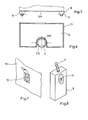
- FIG. 7 is a detailed view of the box,
- - Figure 8 is a rear view of the control unit,
- FIGS. 9 and 10 are views of the means for adjusting the position of the bed tray in longitudinal inclination,
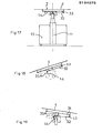
- - Figures 11 to 13 are schematic views showing different possibilities of Longitudinal inclination of the plate,
- FIG. 14 is a sectional view along line II / II of FIG. 4,
- - Figures 15 and 16 are detailed views of the means for adjusting the side tilt table,
- - Figures 17 to 19 are schematic views showing the different possibilities of lateral tilting of the plate,
- FIG. 20 is a schematic perspective view of the means for positioning the radiographic cassette,
- FIGS. 21 and 22 are detailed views of the means for adjusting the inclination of one sector relative to the other,
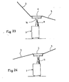
- - Figures 23 and 24 are schematic views showing different possibilities of inclination of the sectors relative to each other.
TeL que représenté, Le Lit médical selon l'invention comprend un piètement 1, un plateau 2 en plusieurs secteurs 3, 4, 5 recevant respectivement La zone dorsale, La zone fémorale et La zone des membres inférieurs du malade, des moyens de réglage de La position du dit plateau en hauteur et en inclinaison latérale et longitudinale et des moyens de réglage de La position des secteurs Les uns par rapport aux autres.TeL as shown, The medical bed according to the invention comprises a
Selon l'exemple préférentiel de réalisation, Le piètement 1 est doté d une poutre maitresse 7 sur laquelle sont montés Les moyens de réglage de La position du plateau en inclinaison LongitudinaLe.According to the preferred embodiment, the
La variation de L inclinaison longitudinale est obtenue par rotation du plateau autour d'un axe transversal dans un sens ou dans L'autre Sur ces moyens, sont montés les moyens de réglage de La position du plateau en inclinaison LatéraLe.The variation of the longitudinal inclination is obtained by rotation of the plate around a transverse axis in one direction or in the other. On these means, the means for adjusting the position of the plate in lateral inclination are mounted.
La variation d'inclinaison latérale est obtenue par rotation dans un sens ou dans L'autre du plateau autour d'au moins un axe longitudinal au dit plateau.The variation in lateral inclination is obtained by rotation in one direction or in the other of the plate around at least one longitudinal axis to said plate.
Sur les moyens de réglage de La position du plateau en inclinaison latérale est monté Le secteur médian 4,On the means for adjusting the position of the tilting platform side mounted The
Ces différents moyens sont agencés de manière à former une configuration dite en chaine ouverte, ce qui d'une part conduit à une simplification de réalisation d'un tel Lit et d autre part permet La commande simultanée de différents mouvements.These different means are arranged so as to form a configuration known as an open chain, which on the one hand leads to a simplification of production of such a bed and on the other hand allows the simultaneous control of different movements.
Les moyens de réglage de La position du Lit en hauteur et en inclinaison et les moyens de réglage de La position des secteurs 3, 4 et 5 du plateau 2 les uns par rapport aux autres sont commandés par des boutons poussoirs disposés dans un boitier 8 relié par un cable électrique souple 9 aux commandes des différents moyens.The means for adjusting the position of the bed in height and tilt and the means for adjusting the position of the
Le piétement 1 est constitué par une semelle 10 horizontale dotée d organes de roulement et par une colonne verticale 11 portant en extrémité La poutre maitresse 7.The
La semelle 10 est constituée par deux longerons parallèles 12 espacés, dotés des organes de roulement et par une paroi horizontale 10A métalLique, de forme rectangulaire fixée sur Les dits longeronsThe sole 10 is constituted by two
A proximité d'un des bords de La paroi est fixée de toute manière connue La colonne 11.Near one of the edges of the wall,
Cette colonne est de préférence télescopique en sorte de régler La position du plateau en hauteur.This column is preferably telescopic so as to adjust the position of the tray in height.
Avantageusement, La colonne 11 est constituée par un vérin hydrauLique, télescopique de tous types connus.Advantageously, the
Ce vérin est avantageusement doté d un carter de protection télescopique 11B.This cylinder is advantageously provided with a telescopic protective casing 11B.
Entre ce carter et Le vérin sont disposés en spirale les conduites du circuit hydraulique.Between this casing and the jack, the hydraulic circuit lines are arranged in a spiral.
Ces conduites sont fixées par tous moyens connus au carter de protection.These pipes are fixed by any known means to the protective casing.
Ce vérin est associé à un circuit hydraulique constitué par un réservoir R de liquide, par une pompe pour injecter le liquide dans une des chambres du vérin 11 et par un distributeur à trois positions dont deux sont affectées à La commande du sens de circulation du fluide hydraulique dans Le vérin et par conséquent au mouvement de sortie et de rentrée de La tige et dont L'autre est affectée à L'arret de La circulation du fluide et donc à l'arret de ces deux mouvements.This cylinder is associated with a hydraulic circuit constituted by a reser see R of liquid, by a pump for injecting the liquid into one of the chambers of the
De préférence, Le distributeur du vérin 11 est du type de ceux pilotés par électro-aimant.Preferably, the distributor of the
Les électro-aimants de ce distributeur sont commandés à partir de pLusieurs bou.tons poussoirs du boitier 8.The electromagnets of this distributor are controlled from several push buttons of the
Les différents éléments du circuit hydraulique du vérin 11 sont Logés dans un caisson 13 monté sur La semeLLe 10 du piètement.The various elements of the hydraulic circuit of the
Comme on peut Le voir en figure 1, Le caisson sensiblement de forme parallèlépipèdique couvre toute la surface de La paroi horizontale 10A et s'étend transversalement au plateau du Lit.As can be seen in FIG. 1, the substantially parallelepiped-shaped box covers the entire surface of the horizontal wall 10A and extends transversely to the bed tray.
Une des parois verticales du caisson 13 est dotée d une forme en creux 13A s étendant verticalement pour recevoir La colonne 11.One of the vertical walls of the
Cette forme en creux est obtenue par cambrage ou par tout autre procédé connu.This hollow shape is obtained by bending or by any other known method.
Avantageusement, Le réservoir R est doté également d'une forme en creux pour recevoir La zone cambrée de La paroi du caissonAdvantageously, the reservoir R is also provided with a hollow shape to receive the arched zone of the wall of the box.
Sur ce réservoir est montée La pompe et Le moteur électrique de La dite pompe.The pump and the electric motor of the said pump are mounted on this tank.
Pour des raisons de sécurité, Le réservoir R est constitué en un matériau non conducteur d'électricité.For safety reasons, the tank R is made of a material which does not conduct electricity.
Avantageusement, Le réservoir R est monté sur organe élastique pour supprimer Les transmissions de vibrations sur La colonne 11 et donc au plateau 2.Advantageously, the reservoir R is mounted on an elastic member to eliminate the transmission of vibrations on the
Selon un exemple préférentiel de réalisation, les organes élastiques sont constitués chacun par un bloc en matériau élastique par exemple du caoutchouc.According to a preferred embodiment, the elastic members each consist of a block of elastic material, for example rubber.
En bout de La tige du vérin 11 est montée suivant l'axe transversal du plateau la poutre maitresse horizontale 7.At the end of the rod of the
Cette poutre maitresse de préférence métallique se présente sous La forme d'un cylindre plein.This preferably metallic master beam is in the form of a solid cylinder.
La poutre est engagée et bloquée en translation et en rotation dans un orifice cylindrique ménagé dans La partie supérieure de la tige du piston et s'étend transversalement au plateau 2 du lit.The beam is engaged and locked in translation and in rotation in a cylindrical orifice formed in the upper part of the piston rod and extends transversely to the
Sur cette poutre maitresse sont montés Les moyens de réglage de la position du plateau 2 en inclinaison longitudinale.On this master beam are mounted The means for adjusting the position of the
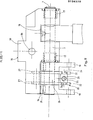
Selon un exemple préférentiel de réalisation, ces moyens sont constitués par un sabot 14 monté articulé sur La poutre maitresse 7 et portant Les moyens de réglage de La position du plateau en inclinaison LatéraLe et par un organe moteur 15 d entrainement en rotation du dit sabot autour de La dite poutre dans un sens ou dans l'autre.According to a preferred embodiment, these means are constituted by a
Comme on peut Le voir plus particulièrement en figures 9 et 10, Le sabot de préférence métallique se présente sensiblement sous La forme d'un parallèlèpipède doté d'une entaille 16 de forme rectangle.As can be seen more particularly in FIGS. 9 and 10, the shoe, preferably metallic, is substantially in the form of a parallelepiped provided with a
Le sabot 14 est doté de deux paliers 17 connus en soi dans lesquels est engagée La poutre maitresse 7.The
Entre ces deux paliers, Le sabot présente un évidement 18 transversal dans lequel s'engage L'extrémité supérieure des moyens de réglage de La position du plateau en hauteur.Between these two bearings, the shoe has a
Latéralement au vérin 11 et sous l'entaille 16 est monté L'organe moteur 15 d'entrainement en rotation du sabot 14 autour de La poutre 7.Lateral to the
L organe moteur constitué de préférence par un vérin hydraulique est articulé par son corps à deux pattes 19 solidaires de La poutre maitresse 7 inclinées par rapport à l axe du vérin 11 et par L'extrémité de sa tige à une patte 20 fixée au sabot 14.The drive member preferably consisting of a hydraulic cylinder is articulated by its body with two
Comme on Le comprend, Le mouvement de sortie ou de rentrée de La tige du vérin entraine Le sabot 14 en rotation autour de La poutre maitresse 7.As can be understood, the movement of exit or re-entry of the rod of the jack causes the
La position du sabot 14 en figure 10 est celle correspondant à La position horizontale du secteur médian du plateau ou de son axe longitudinaLThe position of the
On peut voir également sur cette figure que La tige du verin 15 est à mi-course.It can also be seen in this figure that the rod of the
De ce fait, à partir de La position représentée en figure 10, Le sabot 14 peut etre entrainé en rotation autour de La poutre 7 dans un sens ou dans L'autre par Le mouvement de sortie ou de rentrée de La tige du vérin, et Le plateau 2 peut s incliner suivant une position déclive ou proclive.Therefore, from the position shown in Figure 10, the
On peut voir également que Le plateau 2 est maintenu écarté de La poutre maitresse 7 (figure 11).It can also be seen that the
De ce fait, Le plateau 2 à partir d une position horizontale peut disposé suivant une position verticale par rotation autour de La poutre maitresse 7 cbrrespondant à une position proclive (figure 12). Suivant cette position, Le secteur 3 est une position supérieure et Le secteur 5 en position inférieure.Therefore, the
Suivant cette position, La tige du vérin 15 est enfoncée dans Le corps du vérin.According to this position, the rod of the
De ce fait, à partir de La position, verticale précédemment définie, Le plateau du Lit d un mouvement continu et par rotation autour de La poutre maitresse 7 peut etre disposée en position déclive (figure 13).Therefore, from the vertical position previously defined, the bed tray of a continuous movement and by rotation around the
Ce mouvement est commandé par le mouvement de déploiement de La tige du vérin 15.This movement is controlled by the deployment movement of the rod of the
Suivant cette position, Le secteur 5 est surélevé par rapport au secteur 3.According to this position,
A titre d'exemple, Le plateau du Lit suivant La position déclive est incliné à 20° en arrière par rapport à l'horizontaleFor example, the next bed tray The declining position is tilted 20 ° back from the horizontal
Le circuit hydraulique du vérin 15 est associé à la pompe et au réservoir R et comporte un distributeur piloté par un électro-aimant à trois positions distinctes relative respectivement au mouvement de sortie de La tige, au mouvement de rentrée et à l'arret de ces deux mouvements'.The hydraulic circuit of the
Ce distributeur est monté dans Le caisson 13 et ses électro-aimants sont commandés à partir de plusieurs boutons poussoirs du boitier 8.This distributor is mounted in the
Comme on peut Le voir en figures 9 et 10, les deux pattes 19 sont dotées d'un orifice cylindrique pour venir se monter sur la poutre 7. Les pattes 19 sont bloquées en rotation par rapport à la poutre de préférence par des clavettes 21.As can be seen in FIGS. 9 and 10, the two
En extrémité libre les pattes 19 sont dotées chacune d'un orifice cylindrique dans lequel s'engage Le pivot d articulation du verin 15. Suivant Le plan médian aux 'deux pattes 19 et transversal à La poutre 7 est montée sur Le sabot 14 La patte 20.At the free end, the
La patte 20 présente deux ailes 22 inférieures, parallèles au plan médian sus-énoncé et écartées l'une de L'autreThe
Entre ces deux ailes est monté, de manière articulé un organe de fixation 23 de l'extrémité de La tige du vérin 15.Between these two wings is mounted, in an articulated manner a fixing
Comme on peut le voir plus particulièrment en figure 9, cet organe de fixation de forme parallèlèpipèdique ou cylindrique reçoit deux tourillons latéraux 24 engagés dans un orifice cylindrique ménagé dans chaque aile 22.As can be seen more particularly in FIG. 9, this fixing member of parallelepipedal or cylindrical shape receives two
L'organe 23 est doté d'un orifice cylindrique 25 fileté disposé suivant Le plan médian aux deux pattes 19 et transversal à La poutre 7. Dans cet orifice est engagé L'extrémité filetée de La tige du vérin 15.The
Il est bien évident que La tige du vérin 15 peut etre dotée d une cha- pe coopérant avec un axe solidaire de La patte 20.It is obvious that the
Afin d'éviter les efféts de torsion du sabot 14 par rapport à La poutre 7 lors du passage ou du tirage exercé par la tige du verin sur La patte 20, ceLLe-ci est dotée d un palier 25 engagé sur La dite poutre entre les deux pattes 19.In order to avoid the effects of torsion of the
Comme on Le comprend, La poutre 7 par L'intermédiaire du palier 26 encaisse les efforts de torsion du sabot 14.As can be understood, The
De préférence, La patte 20 est également dotée de deux ailes supérieures 27 parallèles et transversales à la poutre 7 entre LesqueLLes est monté un organe de fixation 28 au sabot 14.Preferably, the
Cet organe de fixation est doté d'une semelle 29 fixée par tous moyens connus au sabot 14 et d'un bossage 30 sur La dite semelle engagé entre Les deux ailes 27.This fixing member is provided with a sole 29 fixed by any means known to the
Cette disposition a pour but de faciliter Le montage de La patte 20 Les ailes 27 et Le bossage sont percés suivant un meme axe d un orifi-. ce cylindriqué transversal dans lequel est engagé une goupiLLe 31 de solidarisation de La patte 20 à L organe 28 et donc au sabot 14.The purpose of this arrangement is to facilitate the mounting of the
Comme dit précédemment, Le sabot porte Les moyens de réglage de La position du plateau en inclinaison LatéraLe.As said previously, the shoe carries the means for adjusting the position of the plate in lateral inclination.
Ces moyens permettent d'incliner Le plateau 2 d'un coté ou de l'autre du Lit.These means make it possible to tilt the
Ces moyens sont constitués par un chassis inférieur 32 articulé au sabot 14 suivant un axe AA' longitudinal au plateau par un chassis supérieur 33, articulé au précédent suivant un axe BB' parallèle à l'axe AA repliable sur le dit chassis inférieur et solidaire de l'ossature du secteur médian 4, par au moins un organe moteur 34 d entrainement en rotation du dit chassis inférieur et supérieur autour de L'axe AA' en sorte d'incliner Le dit plateau suivant un des cotés du lit et par au moins un organe moteur 35 d entrainement en rotation autour de L'axe BB' par L'intermédiaire d un levier 35A du dit chassis supérieur en sorte d'incliner Le plateau 2 suivant L'autre coté du Lit.These means are constituted by a
Le chassis' inférieur est constitué par un axe d articulation 36 et par au moins deux tringles d'égales longueurs 37 perpendiculaires au dit axe 36 solidaires par une de leur extrémité du dit axe et articulées par Leur autre extrémité au chassis supérieurThe lower chassis is constituted by a
L'axe d articulation 36 est monté en rotation dans un orifice cylindrique ménagé dans le support 14 suivant L'axe longitudinal AA Avantageusement, cet orifice est doté de deux paliers dans lesquels est monté rotatif L'axe 36The
Cet axe est maintenu en translation par rapport au sabot 14 par tous moyens connus de L'homme de L art.This axis is maintained in translation relative to the
Cet axe comme on Le voir en figure 7 est transversal au dit sabot 4 et centré latéralement par rapport à celui-ci,This axis as can be seen in FIG. 7 is transverse to said
A chaque extrémité de L'axe 36 est fixé L'extrémité d une des tringles 37.At each end of the
Ces tringles de section transversale rectangulaire sont dotées d un orifice cylindrique transversal pour d une part se monter sur L'axe 36 et d'autre part s articuler au chassis supérieur 33.These rods of rectangular cross section are provided with a transverse cylindrical orifice for on the one hand to be mounted on the
L orifice de chaque tringle dans lequel est engagé l'axe 36 et Le dit axe sont percés d un meme orifice diamètral pour recevoir une goupille de solidarisation ou tous autres moyens mécaniques connus.The orifice of each rod in which the
Le chassis inférieur 32 est également doté de deux tringles 38 de section transversale rectangulaire disposées respectivement de part et d'autre du sabot 14.The
Ces tringles de meme Longueur que les tringles 37 et parallèles à celLes-ci sont également dotée chacune et à chaque extrémité d'un orifice cylindrique transversal pour d'une part se monter et etre fixer à L'axe 36 et d'autre part pour s'articuler au chassis supérieur 33These rods of the same length as the
Les tringles 38 sont en appui contre Le sabot 14 afin d assurer Le maintien longitudinal-du plateau en position verticale. Avantageusement, les tringles 38 présentent au niveau de leur appui contre Le sabot 14 une largeur plus importante et Le dit sabot à ce niveau est doté d'une surépaisseur 39.The
Cette disposition permet d augmenter les surfaces du sabot et des tringles en appui les unes contre Les autres.This arrangement makes it possible to increase the surfaces of the shoe and of the rods resting against each other.
Comme dit précédemment, Le chassis 32 et Le chassis 33 sont mus conjointement en rotation autour de L'axe AA par L'organe moteur 34. Comme on peut Le voir en figure 4Bis et 16, cet organe moteur est disposé sous Le chassis inférieur entre les tringles 38 et entre Le sabot 14 et l'axe d'articulation BB'.As said before, The
Cet organe moteur est constitué de préférence par un vérin hydraulique articulé par son corps à deux pattes 40 solidaires du sabot 14 et par sa tige au chassis inférieur.This drive member preferably consists of a hydraulic cylinder articulated by its body with two
A partir de la position horizontale représentée en figure 17, l'organe moteur commande La rotation du chassis inférieur du chassis supérieur et par conséquent du plateau 2 autour de l'axeAA', en sens contraire des aiguiLLes d une montre pour incliner ceux-ci suivant un des cotés du Lit (figure 18).From the horizontal position shown in FIG. 17, the motor member controls the rotation of the lower chassis of the upper chassis and consequently of the
Les deux pattes 40 sont fixées par tous moyens connus de l'homme de L'art au sabot 14,The two
Ces deux pattes sont montées chacune contre un des flans longitudinaux 14A du sabot de préférence dans une forme en creux.These two tabs are each mounted against one of the
Une des extrémités de chaque patte est en saillie sur La face arrière 14B afin de recevoir Le verin 34.One end of each leg projects from the
Ce verin est monté de manière articulée entre celles-ci.This cylinder is mounted in an articulated manner between them.
A cet effet, L'extrémité libre de chaque patte est dotée d'un orifice cylindrique transversal dans lequel est engagé un tourillon solidaire du corps du verin.To this end, the free end of each leg is provided with a transverse cylindrical orifice in which is engaged a pin fixed to the body of the jack.
L extrémité de la tige du verin est articulée de préférence aux deux tringles 38 du chassis inférieur.The end of the cylinder rod is preferably hinged to the two
Selon un exemple préférentiel de réalisation L'extrémité filetée de La tige du verin est montée dans un orifice cylindrique fileté d'un axe 41 disposé entre Les tringles 38 parallèlement à l'axe 36 et articulé par chacune de ses extrémités à chaque tringle 38,According to a preferred exemplary embodiment, the threaded end of the cylinder rod is mounted in a cylindrical orifice threaded with an
A cet effet, cet axe 41 à chaque extrémité présente un touriLLon engagé dans un orifice cylindrique ménagé dans chaque tringle 38.To this end, this
IL est bien évident que tout autre type d'articulation pourra etre utiliséIt is obvious that any other type of joint can be used
Le circuit du verin hydraulique 34 à la pompe et au réservoir R est doté d'un distributeur à trois positions distinctes dont deux commandent Les mouvements de La tige du verin et dontl autre est affectée à l'arret de ces deux mouvements.The circuit of the
Ce distributeur est monté dans Le caisson 13 Les électro-aimants sont commandés par des boutons poussoirs du boitier 8.This distributor is mounted in the
Comme dit précédemment, Le chassis supérieur est articulé au chassis inférieur suivant L'axe BB'.As said previously, the upper chassis is articulated to the lower chassis along the axis BB '.
Ce chassis supérieur est constitué par deux axes 42 et 43 parallèles à l'axe 36 du chassis inférieur 32 solidaires tous deux de L'ossature du secteur médian 4 dont un axe 42 est monté en rotation en extrémité des tringles 37 et 38 du chassis inférieur suivant L'axe BB' et par des tringles 44 parallèles à ceLLes du chassis inférieur.This upper chassis is constituted by two
Ces tringles d'égales dimensions présentent une longueur supérieure à ceLLe du chassis inférieur.These rods of equal dimensions have a length greater than that of the lower chassis.
Comme on peut Le voir en figure 15, l'axe 43 est disposé au-dessus du plan défini par les axes 36 et 42.As can be seen in FIG. 15, the
Les tringles 44 de section transversale rectangulaire, présentent chacune une extrémité coudée à angle droit pour rattraper la différence de niveau existant entre ces deux axes.The
A chaque éxtrémité Les tringles 44 présentent un orifice cylindrique transversal pour s'engager sur Les axes 43.At each end The
Les tringles 44 Lorsque Le chassis supérieur est replié sur Le chassis inférieur sont en appui sur l'axe 36.The
De ce fait, Le chassis supérieur ne pourra etre écarté du chassis inférieur que suivant un seul sens de rotation.As a result, the upper chassis can only be moved away from the lower chassis in one direction of rotation.
Comme dit précédemment, Le chassis supérieur est mu en rotation autour de L'axe BB' par l'organe moteur 35 par L'intermédiaire d'un levier 35A.As said previously, the upper chassis is rotated around the axis BB 'by the
Comme on peut Le voir en figure 4A, Le Lit selon l'invention est équipé de deux organes moteurs 35 disposés de part et d'autre du sabot 14 entre deux tringles 44 et entre L'axe 43 et L'axe 36.As can be seen in FIG. 4A, the bed according to the invention is equipped with two
Chaque organe moteur constitué par un verin hydraulique est articuLé par son corps, deux pattes 358 solidaires de l'axe 36 et par sa tige au levier 35A disposé sous le chassis inférieur.Each motor member constituted by a hydraulic cylinder is articulated by its body, two legs 358 secured to the
Les deux pattes 35B sont dotées chacune à une de Leur extrémité d un élément cylindrique tubulaire engagé et bloqué sur L'axe 36 par clavetage ou tout autre procédé.The two
Ces pattes sont disposées entre deux tringles 44 ces deux tringles étant disposées latéralement au sabot parallèlement à sa face 14A longitudinale.These legs are arranged between two
Ces deux pattes 35B sont espacées l'une de L'autre pour recevoir de manière articulée le corps du verin 35.These two
A cet effet, L'extrémité libre de chaque patte est doté d'un orifice cylindrique transversal dans LequeL s'engage un tourillon solidaire du corps du verin.For this purpose, the free end of each leg is provided with a transverse cylindrical orifice in LequeL engages a pin secured to the body of the actuator.
Entre ces deux pattes et sur l'axe 36 est monté rotatif le levier 35A. Ce levier 35A coudé à angle droit est articulé au niveau de son coude à l'axe 36_et est doté à une de ses extrémités d'une galet 46 en appui contre Le thassis supérieur.Between these two legs and on the
A l'autre extrémité du Levier est articulée la tige du verin 35.At the other end of the lever is articulated the rod of the
La figure 15 montre Le chassis supérieur replié sur Le chassis inférieur. Lors du déploiement de La tige du verin, celle-ci agit sur le Levier 35A et Lui communique un mouvement de rotation en sens contraire des aiguilles d'une montre autour de L'axe 36.Figure 15 shows The upper chassis folded over The lower chassis. During the deployment of the rod of the jack, it acts on the
Lors de son mouvement, le levier 35A par L'intermédiaire du galet 46 écarte Le chassis supérieur et L'ossature du secteur 4 du chassis inférieur.During its movement, the
Ce mouvement d'écartement se fait par rotation, autour de l'axe BB' dans Le sens des aiguilles d une montre pour incliner Le plateau 2 de L'autre cote du Lit.This spacing movement is done by rotation, around the axis BB 'clockwise to tilt the
Comme on peut Le voir en figure 19 au cours du mouvement de basculement du chassis supérieur 33 autour de l'axe BB', Le point de contact du galet 46 au dit chassis s'écarte du dit axe BB' ce qui accroit La stabilité.As can be seen in FIG. 19 during the tilting movement of the
Avantageusement, Le galet 46 est en contact avec une plaque métallique 47 du chassis supérieur fixée par tous moyens connus entre deux tringles 44.Advantageously, the
Selon un autre exemple de réalisation, le galet 46 est en appui contre un chemin de roulement connu en soit disposé entre deux tringles 44 et solidaire de celles-ci par tous moyens ou procédés connus.According to another exemplary embodiment, the
Le Lit étant doté de deux organes moteurs 35, il sera également doté de quatre pattes 46 de deux Leviers 35A et de deux pLaques 47.The bed being provided with two driving
Le circuit hydraulique de chaque organe moteur 35 associé à la pompe et au réservoir R est doté d'un distributeur hydraulique à trois positions dont deux sont affectées au mouvement de La tige et dont L'autre est affectée à L'arrêt de ces deux mouvements.The hydraulic circuit of each
Les élactro-aimants de chaque-distributeur sont commandés par des boutons poussoirs du boitier 8.The electromagnets of each distributor are controlled by pushbuttons on the
L'ossature du secteur médian4 est centrée par rapport àu moyen de régLage de La position du plateau en hauteur afin de centrer les charges sur ce moyen.The framework of the middle sector4 is centered relative to the means for adjusting the position of the height platform in order to center the loads on this means.
Cette ossature de forme rectangulaire est constituée par l'assemblage de deux traverses inférieures 48 transversales au plateau du dit Lit avec au moins deux longerons 49 supérieurs parallèles à l'axe Longitudinal du plateau du Lit.This rectangular frame is formed by the assembly of two
Les traverses 48 inférieures métalliques de préférence tubulaires et de section transversale carrée sont montées respectivement de part et d autre du chassis supérieur et sont solidaires chacune d'une extrémité de L'axe 42 et d une des extrémités de l'axe 43.The
Ces traverses sont dotées d'orifices transversaux dans chacun desquels est monté un étéments tubulaire cylindrique afin de recevoir une des extrémités de l'axe 42 ou 43.These crosspieces are provided with transverse orifices in each of which is mounted a cylindrical tubular element in order to receive one of the ends of the
Avantageusement, ces axes sont terminés par un filetage afin de recevoir un écrou de blocage à La traverse, Le dit écrou après montage est judicieusement solidarisé en rotation par tous moyens connus sur son axe.Advantageously, these axes are terminated by a thread in order to receive a locking nut at the crosspiece, said nut after assembly is judiciously secured in rotation by any known means on its axis.
Afin de rattraper La différence de niveau entre Les axes 42 et 43, les traverses à une de leurs extrémités présentent chacune une surépaisseur 50 rapportées dans LaqueLLe s'engage L'extrémité de l'axe 43. Les Longerons supérieurs 49 tubulaires de section transversale carrée sont solidaires chacun par deux pattes 51 de L'extrémité d'une des traverses.In order to make up for the difference in level between the
Comme on peut Le voir en figure 14, ces pattes sont perpendiculaires aux traverses et aux Longerons.As can be seen in Figure 14, these legs are perpendicular to the crosspieces and the Longerons.
Cette disposition a pour but de maintenir écarté les longerons des traverses et donc du chassis supérieur 33 pour des raisons qui seront énoncées plus avant.The purpose of this arrangement is to keep the side members of the cross members and therefore of the
L'ossature est également dotée de deux Longerons 52 disposés suivant L'axe longitudinal du plateau du Lit et formant deux des cotés du secteur médian 4.The framework is also endowed with two
Chaque longeron 52 comme on peut le voir en figure 4 est disposé à coté d'un des longerons 49 et est réuni à celui-ci par trois entret- roises 53 transversales au plateau et disposées respectivement à chacune des extrémités des dits longerons et suivant La zone médiane de ceux-ci.Each
A L'ossature du secteur médian 4 précédemment définie sont articulés les secteurs 3 et 5.At the framework of the previously defined
L'ossature de ces secteurs est constituée par deux longerons parallèLes 54 réunis par une traverse 55 d'extrémité.The framework of these sectors is constituted by two
Chaque Longeron 54 est articulé par son extrémité libre à une des extrémités d'un des longerons 52.Each
A cet effet, chaque longeron 52 et chaque Longeron 54 présentent en extrémité un bossage 55 A percé d'un orifice cylindrique recevant un axe d'articulation.To this end, each
Au niveau de chaque articulation avec L'un quelconque des secteurs 3 ou 5 Le secteur médian 4 est équipé de moyens de réglage de l'inclinaison d'un des dits secteurs par rapport au dit secteur médian 4. Ces moyens de réglage sont constitués par un Levier 56 articulé au secteur médian 4 sous un des secteurs 3 ou 5 et par un organe moteur 57 tel un verin hydraulique articulé par son corps au dit secteur médian et par sa tige au dit Levier.At each articulation with any of the
Le Levier 56 est articulé à deux pattes 58 solidaires respectivement des Longerons 49 et 52 du secteur médian 4.The
Ce levier est articulé suivant un axe parallèle à l'axe d'articulation des secteurs Les uns par rapport aux autres.This lever is articulated along an axis parallel to the axis of articulation of the sectors relative to each other.
Ce levier de section transversale rectangulaire est coudé et est monté entre les pattes 58.This rectangular cross-section lever is bent and is mounted between the
Au niveau de son coude Le Levier est doté d'un orifice cylindrique transversal dans lequel est engagé un axe 59 d'articulation aux pattes 58.At its elbow, the lever has a transverse cylindrical orifice in which an
A une des extrémités du Levier est articulé par tous moyens connus La tige du verin 57.At one end of the lever is articulated by any known means The rod of the
Ce verin est articulé par son corps par tous moyens connus par exemple à deux pattes solidaires toutes Les deux de L'entretoise médiane 53 et solidaires respectivement des Longerons 49 et 52.This cylinder is articulated by its body by any known means, for example with two legs which are both secured to the
Cette disposition permet Le montage des verins de faibles dimensions, pour éviter L'usure de L'aLesage de'guidage de La tige.This arrangement allows the mounting of small-sized cylinders, to avoid wear and tear of the rod guide.
L'autre extrémité du levier 56 est dotée d'un galet 60 rotatif en appui contre Le secteur 3 ou 5.The other end of the
On pénètre dans Le corps du dit verin lorsque La tige du verin se déploie, Le Levier 56 est mu en rotation autour de son axe d'articulation 59 et le galet 60 en appui contre Le secteur 3 ou 5 pousse celui-ci vers Le haut en sorte de l'incliner par rapport au secteur 4. Différentes positions des secteurs Les uns par rapport aux autres sont représentées en figures 23 et 24.We enter the body of said actuator when the actuator rod is deployed, the
Avantageusement, Le secteur 3 et Le secteur 5 sont dotés de chemin de roulement 61 coopérant respectivement avec un galet 60.Advantageously, the
Comme on peut Le voir en figure 22, chaque chemin de rouLemenL est ménagé dans un élément tubulaire 62 fixé par tous moyens connus à un longeron 54.As can be seen in FIG. 22, each rolling path is formed in a
Cet élément tubulaire de section transversale carrée présente une Lumière inférieure 62A pour Le passage du levier et du galet 60.This tubular element of square cross section has a
Ce galet 60 est en appui contre Le chemin de roulement 61 constitué sur La face interne de La paroi supérieure de L'éLémeht 62.This
Un onifice latéral 62B est ménagé dans L'éLément 62 pour permettre Le montage du'ou des galets et de l'axe.A lateral orifice 62B is provided in the
L'ossature de chaque secteur est recouverte de plaque 63 en matière radiotransparente de tous tupes connus.The framework of each sector is covered with a
Pour radiographier La zone fémorale du patient, Le secteur médian 4 reçoit au-dessus des traverses 48 une cassette radiographique 64 de tout type connu et un système de positionnement de celle-ci.To x-ray the femoral area of the patient, the
Ce système comme représenté schématiquement en figure 20 est constitué par quatre poulies 65 réunies deux à deux par un cable 66 auquel est fixée La cassette.This system as shown diagrammatically in FIG. 20 consists of four
Deux de ces poulies sont associées à une poignée 66A de manoeuvre. Afin de protéger Le système d'entrainement deux plaques 67 sont fixées respectivement aux deux Longerons 52.Two of these pulleys are associated with an
Sur les plaquis en matière radiotransparente chaque secteur est doté d un matelas de tout type connu.On the radiolucent material sheets each sector is fitted with a mattress of any known type.
Ce matelas est fixé par exemple sur sa plaque par des bandes adhésives, par exemple par des bandes connues sous le nom commercial de "VECRO".This mattress is fixed for example on its plate by adhesive strips, for example by strips known under the trade name of "VECRO".
Egalement, chaque secteur est doté d au moins un rait 68 fixé selon Le cas au Longeron 52 ou au longeron 54.Also, each sector is endowed with at least one
A ce rail peuvent etre fixés par tous moyens connus divers instruments médicaux.
- En figure 1, on voit qu'à ce rail est fixé un bac de perroquet 69.
Le secteur 2 recevant La zone dorsale du patient est équipée d un appui tete 70 amovible de tous types connus.
- In FIG. 1, it can be seen that this
parrot trough 69 is fixed. -
Sector 2 receiving The patient's back area is equipped with aremovable head support 70 of all known types.
Avantageusement, Le secteur 5 recevant La zone des membres inférieurs est doté de deux repose pieds amovibles 71.Advantageously, the
IL est à noter qu'en position verticale Le secteur 5 peut etre disposé au niveau du sol afin-de permettre au malade de monter sur les repose pieds et d_incliner à L'aide du boitier 8 de commande Le pLateau du Lit vers L'arrière.It should be noted that in a
IL est bien évident que Le Lit selon L'invention est équipé de tous accessoires connus, notamment deux gards corps amovibles.It is obvious that The Bed according to the invention is equipped with all known accessories, in particular two removable body guards.
De meme, Le circuit hydraulique et Le circuit électrique du Lit sont équipés de toutes les sécurités nécessaires.Likewise, the hydraulic circuit and the electric circuit of the bed are equipped with all the necessary safety devices.
C est ainsi que Le Lit comporte un interrupteur 72 de mise sous tension fixé au caisson et protégé par un volet verrouillableThis is how Le Lit has a power-
De plus, Le boîtier 8 est alimenté en basse tension par exemple en 12V et comporte un bouton poussoir 73 disposé en série sur Le circuit de commande des électro-aimants.In addition, the
De ce fait, L'utiLisateur pour commander les différents mouvements devra d'abord agir sur Le bouton poussoir 73, puis sur Le bouton poussoir adéquat.Therefore, the user to control the different movements must first act on the
Cette disposition a pour but d'éviter que l'utilisateur ne puisse ino- pinément manoeuvrer Le Lit. De préférence, le bouton poussoir 73 est disposé sur La face arrière du boitier 8 pour renforcer La caractéristique précédemment énoncée.This provision aims to ensure that the user can manipulate ino- p inément The Lit. Preferably, the
La présente invention peut recevoir tous aménagements et toutes variantes sans pour autant sortir du cadre du présent brevet.The present invention can receive all arrangements and all variants without departing from the scope of this patent.
Claims (16)
Priority Applications (5)
| Application Number | Priority Date | Filing Date | Title |
|---|---|---|---|
| FR8204949A FR2523437A1 (en) | 1982-03-18 | 1982-03-18 | MEDICAL BED |
| EP83401773A EP0134370B1 (en) | 1982-03-18 | 1983-09-12 | Medical bed |
| DE8383401773T DE3375074D1 (en) | 1983-09-12 | 1983-09-12 | Medical bed |
| AT83401773T ATE31621T1 (en) | 1983-09-12 | 1983-09-12 | MEDICAL BED. |
| US06/534,626 US4557471A (en) | 1982-03-18 | 1983-09-16 | Medical bed |
Applications Claiming Priority (3)
| Application Number | Priority Date | Filing Date | Title |
|---|---|---|---|
| FR8204949A FR2523437A1 (en) | 1982-03-18 | 1982-03-18 | MEDICAL BED |
| EP83401773A EP0134370B1 (en) | 1982-03-18 | 1983-09-12 | Medical bed |
| US06/534,626 US4557471A (en) | 1982-03-18 | 1983-09-16 | Medical bed |
Publications (2)
| Publication Number | Publication Date |
|---|---|
| EP0134370A1 true EP0134370A1 (en) | 1985-03-20 |
| EP0134370B1 EP0134370B1 (en) | 1988-01-07 |
Family
ID=27226593
Family Applications (1)
| Application Number | Title | Priority Date | Filing Date |
|---|---|---|---|
| EP83401773A Expired EP0134370B1 (en) | 1982-03-18 | 1983-09-12 | Medical bed |
Country Status (3)
| Country | Link |
|---|---|
| US (1) | US4557471A (en) |
| EP (1) | EP0134370B1 (en) |
| FR (1) | FR2523437A1 (en) |
Cited By (1)
| Publication number | Priority date | Publication date | Assignee | Title |
|---|---|---|---|---|
| US6306082B1 (en) | 1994-03-17 | 2001-10-23 | Olympus Optical Co. | Stereoendoscope wherein images having passed through plural incident pupils are transmitted by common relay optical systems |
Families Citing this family (44)
| Publication number | Priority date | Publication date | Assignee | Title |
|---|---|---|---|---|
| FR2523437A1 (en) * | 1982-03-18 | 1983-09-23 | Idetec Entreprise | MEDICAL BED |
| US4685159A (en) * | 1985-05-09 | 1987-08-11 | Hans Oetiker | Hospital bed |
| FR2591887A1 (en) * | 1985-12-19 | 1987-06-26 | Sautereau Jean Marc | Adjustable obstetrical and/or surgical chair |
| FR2606631B1 (en) * | 1986-11-18 | 1991-03-22 | Medi 2000 Sarl | MEDICAL BED OR MEDICAL TABLE |
| DE3805431A1 (en) * | 1987-09-08 | 1989-03-16 | Siegener Feinmechanik Gmbh | Lounger for nursing and elderly care |
| FR2666013A1 (en) * | 1990-08-27 | 1992-02-28 | Chardon Bernard | Surgical operating table with off-centre column connected to the seat element |
| US5299334A (en) * | 1992-01-21 | 1994-04-05 | Kinetic Concepts, Inc. | Hydraulic oscillating treatment table and method |
| US6212714B1 (en) | 1995-01-03 | 2001-04-10 | Hill-Rom, Inc. | Hospital bed and mattress having a retracting foot section |
| USRE43155E1 (en) * | 1995-01-03 | 2012-02-07 | Hill-Rom Services, Inc. | Hospital bed and mattress having a retractable foot section |
| US6584628B1 (en) | 1995-08-04 | 2003-07-01 | Hill-Rom Services, Inc. | Hospital bed having a rotational therapy device |
| US5678894A (en) * | 1996-04-08 | 1997-10-21 | Eley; Christopher D. | Dental chair with headrest |
| AU7548498A (en) * | 1997-07-22 | 1999-02-16 | Kozo Sumiya | Bed for suspending/holding inverted subject for automatic mechanotherapy |
| AU8697998A (en) * | 1997-08-08 | 1999-03-01 | Hill-Rom, Inc. | Proning bed |
| US6427264B1 (en) | 1999-03-19 | 2002-08-06 | Hill-Rom Services, Inc. | Gap filler for bed |
| AU1205201A (en) | 1999-10-15 | 2001-04-30 | Hill-Rom, Inc. | Siderail pad for hospital bed |
| US6691346B2 (en) | 1999-12-29 | 2004-02-17 | Hill-Rom Services, Inc. | Foot controls for a bed |
| EP1263386A1 (en) | 2000-03-17 | 2002-12-11 | Hill-Rom, Inc. | Proning bed |
| CA2415694A1 (en) | 2000-07-14 | 2002-01-24 | John P. Biondo | Pulmonary therapy apparatus |
| US6568008B2 (en) | 2001-06-19 | 2003-05-27 | The Brewer Company, Llc | Medical examination table with two-way drawers and articulating backrest |
| US6550084B2 (en) | 2001-06-19 | 2003-04-22 | The Brewer Company, Llc | Medical examination table step |
| US7100222B2 (en) | 2001-08-22 | 2006-09-05 | Hill-Rom Services, Inc. | Apparatus and method for mounting hospital bed accessories |
| WO2003017905A2 (en) | 2001-08-22 | 2003-03-06 | Hill-Rom Services, Inc. | Apparatus and method for closing hospital bed gaps |
| US6862762B1 (en) * | 2002-01-11 | 2005-03-08 | Wlf, L.L.C. | Patient support apparatus |
| US7073220B2 (en) | 2002-09-06 | 2006-07-11 | Hill-Rom Services, Inc. | Bed siderail having a latch |
| WO2004021952A2 (en) | 2002-09-06 | 2004-03-18 | Hill-Rom Services, Inc. | Hospital bed |
| US6820293B2 (en) | 2002-09-26 | 2004-11-23 | Hill-Rom Services, Inc. | Bed siderail pad apparatus |
| US7350249B2 (en) | 2003-09-29 | 2008-04-01 | The Brewer Company, Llc | Leg rest and kneeler assembly for a medical examination table |
| US7083355B2 (en) | 2003-09-29 | 2006-08-01 | The Brewer Company, Llc | Stirrup support indexer for a medical examination table |
| US7093313B2 (en) | 2003-09-29 | 2006-08-22 | The Brewer Company, Llc | Headrest linkage |
| USD496462S1 (en) | 2003-09-29 | 2004-09-21 | The Brewer Company, Llc | Medical examination table |
| BRPI0508629A (en) | 2004-03-12 | 2007-08-07 | Hill Rom Services Inc | side rail for use with a patient support |
| US7513000B2 (en) | 2005-07-28 | 2009-04-07 | The Brewer Company, Llc | Medical examination table |
| US9038216B2 (en) | 2005-07-28 | 2015-05-26 | The Brewer Company, Llc | Medical examination table |
| US7386899B2 (en) | 2005-09-14 | 2008-06-17 | Midmark Corporation | Medical examination table with pullout step |
| US8104122B2 (en) | 2005-12-19 | 2012-01-31 | Hill-Rom Services, Inc. | Patient support having an extendable foot section |
| US7934276B2 (en) | 2006-02-08 | 2011-05-03 | Hill-Rom Services, Inc. | End panel for a patient-support apparatus |
| US7930778B2 (en) | 2007-12-07 | 2011-04-26 | Hill-Rom Services, Inc. | Pinch-preventing unit for bed guardrail |
| IT1391225B1 (en) * | 2008-10-01 | 2011-12-01 | Castellini Spa | ARMCHAIR FOR DENTAL USE |
| US8646131B2 (en) | 2010-07-30 | 2014-02-11 | Hill-Rom Services, Inc. | Variable height siderail |
| CN102038592B (en) * | 2010-12-31 | 2012-05-23 | 太仓市康辉科技发展有限公司 | Operating table regulating device |
| US8341778B2 (en) | 2011-02-07 | 2013-01-01 | Hill-Rom Services, Inc. | Bed gap filler and footboard pad |
| EP2873400B1 (en) | 2013-11-18 | 2018-01-31 | Völker GmbH | Person support apparatus |
| USD1015004S1 (en) | 2022-03-20 | 2024-02-20 | Yajun Hu | Medical bed |
| USD1012764S1 (en) | 2022-03-30 | 2024-01-30 | Yajun Hu | Medical bed |
Citations (10)
| Publication number | Priority date | Publication date | Assignee | Title |
|---|---|---|---|---|
| DE672192C (en) * | 1936-07-17 | 1939-02-27 | Schaerer Akt Ges M | Operating table |
| FR977566A (en) * | 1942-08-12 | 1951-04-03 | Maison M Schaerer | Operating table |
| GB836776A (en) * | 1955-03-21 | 1960-06-09 | Medical Supply Ass Ltd | Improvements in surgical operating tables |
| FR1306095A (en) * | 1961-08-30 | 1962-10-13 | Ritter Co | Surgical table |
| US3336606A (en) * | 1966-03-24 | 1967-08-22 | Lite Hospital Equipment Inc | Bed for persons having physical disability |
| FR1564040A (en) * | 1968-03-07 | 1969-04-18 | ||
| US3562824A (en) * | 1968-12-30 | 1971-02-16 | William Wayne White | Hammock for invalid beds |
| GB1347920A (en) * | 1972-07-24 | 1974-02-27 | Nat Res Dev | Surgical tables |
| US3868103A (en) * | 1973-04-24 | 1975-02-25 | Millet Roux & Cie Ltee | Surgical and examination table structure |
| FR2523437A1 (en) * | 1982-03-18 | 1983-09-23 | Idetec Entreprise | MEDICAL BED |
Family Cites Families (3)
| Publication number | Priority date | Publication date | Assignee | Title |
|---|---|---|---|---|
| US2217783A (en) * | 1938-06-09 | 1940-10-15 | F O Schoedinger | Operating table |
| US3206188A (en) * | 1961-08-28 | 1965-09-14 | Shampaine Ind Inc | Hydraulically actuated surgical operating tables |
| US4195829A (en) * | 1978-04-21 | 1980-04-01 | Sybron Corporation | Surgical table hydraulic system |
-
1982
- 1982-03-18 FR FR8204949A patent/FR2523437A1/en active Granted
-
1983
- 1983-09-12 EP EP83401773A patent/EP0134370B1/en not_active Expired
- 1983-09-16 US US06/534,626 patent/US4557471A/en not_active Expired - Fee Related
Patent Citations (10)
| Publication number | Priority date | Publication date | Assignee | Title |
|---|---|---|---|---|
| DE672192C (en) * | 1936-07-17 | 1939-02-27 | Schaerer Akt Ges M | Operating table |
| FR977566A (en) * | 1942-08-12 | 1951-04-03 | Maison M Schaerer | Operating table |
| GB836776A (en) * | 1955-03-21 | 1960-06-09 | Medical Supply Ass Ltd | Improvements in surgical operating tables |
| FR1306095A (en) * | 1961-08-30 | 1962-10-13 | Ritter Co | Surgical table |
| US3336606A (en) * | 1966-03-24 | 1967-08-22 | Lite Hospital Equipment Inc | Bed for persons having physical disability |
| FR1564040A (en) * | 1968-03-07 | 1969-04-18 | ||
| US3562824A (en) * | 1968-12-30 | 1971-02-16 | William Wayne White | Hammock for invalid beds |
| GB1347920A (en) * | 1972-07-24 | 1974-02-27 | Nat Res Dev | Surgical tables |
| US3868103A (en) * | 1973-04-24 | 1975-02-25 | Millet Roux & Cie Ltee | Surgical and examination table structure |
| FR2523437A1 (en) * | 1982-03-18 | 1983-09-23 | Idetec Entreprise | MEDICAL BED |
Cited By (2)
| Publication number | Priority date | Publication date | Assignee | Title |
|---|---|---|---|---|
| US6306082B1 (en) | 1994-03-17 | 2001-10-23 | Olympus Optical Co. | Stereoendoscope wherein images having passed through plural incident pupils are transmitted by common relay optical systems |
| US6976956B2 (en) | 1994-03-17 | 2005-12-20 | Olympus Optical Co. | Stereoendoscope wherein images having passed through plural incident pupils are transmitted by common relay optical systems |
Also Published As
| Publication number | Publication date |
|---|---|
| EP0134370B1 (en) | 1988-01-07 |
| FR2523437B1 (en) | 1985-05-24 |
| FR2523437A1 (en) | 1983-09-23 |
| US4557471A (en) | 1985-12-10 |
Similar Documents
| Publication | Publication Date | Title |
|---|---|---|
| EP0134370B1 (en) | Medical bed | |
| FR2674787A1 (en) | COMBINED CUTTING MACHINE AND RECEPTION TABLE. | |
| EP1221348A1 (en) | Workpiece-supporting device for a bending machine | |
| EP0374019A1 (en) | System for transporting and placing at least one bridge element using a vehicle such as a bridge laying vehicle | |
| EP0685599A1 (en) | System for transporting at least two bridge elements on a vehicle for surmounting gaps and system for placing the elements by a vehicle over the gap | |
| FR2862002A1 (en) | CONVERTIBLE BILLIARD TABLE | |
| EP0774223A1 (en) | Deformable undermattress with ergonomic shape | |
| EP0007264A1 (en) | Chain flexible in only one direction and application to a hand rail | |
| EP0188987A1 (en) | Palettizer, in particular for bag parcels | |
| FR2574670A1 (en) | Apparatus with conversion for picking up tennis and golf balls | |
| WO2001032538A1 (en) | Pallet conveying device | |
| EP0757132B9 (en) | Bridge element, especially for surmounting gaps by vehicles and system for transporting and placing the bridge element | |
| FR2762625A1 (en) | INTERMEDIATE LAYER FOR HEIGHT SPACING AND SUPPORT OF LONG RAILS AS WELL AS RAIL LOADING TRAIN THEREFOR | |
| EP0475853A1 (en) | System for transporting a bridge element surmounting gaps and system for placing the bridge element using a vehicle | |
| EP1759580B1 (en) | Cart for containing eggs to be incubated | |
| EP0374194B1 (en) | Systeme for driving carriages on a rail and process for operating same | |
| FR2731614A1 (en) | Transfer mechanism for patient lying on medical trolley etc. | |
| FR2704586A3 (en) | Mechanism for moving a stepped floor of a movable terrace | |
| EP0700862A1 (en) | Lifting platform to raise cars by engaging the chassis or the wheels | |
| EP0359616B1 (en) | Closing machine for containers | |
| EP0123633A1 (en) | Mechanism for a telescopic box on a vehicle | |
| EP0539283A1 (en) | Table for supporting a stretcher | |
| EP0928559A1 (en) | Apparatus and process for slitting pieces of bread dough or the like | |
| EP4166125A1 (en) | Orthopaedic walking assistance device comprising motorisation means and means for spacing the patient's thighs | |
| FR2627691A1 (en) | Surgical table for large animal - has two motor-driven rollers for tilting and positioning animal for surgical procedures |
Legal Events
| Date | Code | Title | Description |
|---|---|---|---|
| PUAI | Public reference made under article 153(3) epc to a published international application that has entered the european phase |
Free format text: ORIGINAL CODE: 0009012 |
|
| AK | Designated contracting states |
Designated state(s): AT BE CH DE FR GB IT LI LU NL SE |
|
| 17P | Request for examination filed |
Effective date: 19850719 |
|
| 17Q | First examination report despatched |
Effective date: 19860903 |
|
| GRAA | (expected) grant |
Free format text: ORIGINAL CODE: 0009210 |
|
| AK | Designated contracting states |
Kind code of ref document: B1 Designated state(s): AT BE CH DE FR GB IT LI LU NL SE |
|
| REF | Corresponds to: |
Ref document number: 31621 Country of ref document: AT Date of ref document: 19880115 Kind code of ref document: T |
|
| REF | Corresponds to: |
Ref document number: 3375074 Country of ref document: DE Date of ref document: 19880211 |
|
| ITF | It: translation for a ep patent filed |
Owner name: ORGANIZZAZIONE D'AGOSTINI |
|
| GBT | Gb: translation of ep patent filed (gb section 77(6)(a)/1977) | ||
| PG25 | Lapsed in a contracting state [announced via postgrant information from national office to epo] |
Ref country code: GB Effective date: 19880912 Ref country code: AT Effective date: 19880912 |
|
| PG25 | Lapsed in a contracting state [announced via postgrant information from national office to epo] |
Ref country code: SE Effective date: 19880913 |
|
| PG25 | Lapsed in a contracting state [announced via postgrant information from national office to epo] |
Ref country code: LU Free format text: LAPSE BECAUSE OF NON-PAYMENT OF DUE FEES Effective date: 19880930 Ref country code: LI Effective date: 19880930 Ref country code: CH Effective date: 19880930 Ref country code: BE Effective date: 19880930 |
|
| PLBE | No opposition filed within time limit |
Free format text: ORIGINAL CODE: 0009261 |
|
| STAA | Information on the status of an ep patent application or granted ep patent |
Free format text: STATUS: NO OPPOSITION FILED WITHIN TIME LIMIT |
|
| 26N | No opposition filed | ||
| BERE | Be: lapsed |
Owner name: PAZZINI NORBERT Effective date: 19880930 |
|
| PG25 | Lapsed in a contracting state [announced via postgrant information from national office to epo] |
Ref country code: NL Effective date: 19890401 |
|
| REG | Reference to a national code |
Ref country code: GB Ref legal event code: PCNP |
|
| NLV4 | Nl: lapsed or anulled due to non-payment of the annual fee | ||
| PG25 | Lapsed in a contracting state [announced via postgrant information from national office to epo] |
Ref country code: FR Free format text: LAPSE BECAUSE OF NON-PAYMENT OF DUE FEES Effective date: 19890531 |
|
| REG | Reference to a national code |
Ref country code: CH Ref legal event code: PL |
|
| GBPC | Gb: european patent ceased through non-payment of renewal fee | ||
| PG25 | Lapsed in a contracting state [announced via postgrant information from national office to epo] |
Ref country code: DE Effective date: 19890601 |
|
| REG | Reference to a national code |
Ref country code: FR Ref legal event code: ST |
|
| EUG | Se: european patent has lapsed |
Ref document number: 83401773.3 Effective date: 19890712 |